EP3013263B1 - Ensemble de distribution ayant un ensemble de mélange et d'immersion et procédés associés - Google Patents
Ensemble de distribution ayant un ensemble de mélange et d'immersion et procédés associés Download PDFInfo
- Publication number
- EP3013263B1 EP3013263B1 EP14739646.9A EP14739646A EP3013263B1 EP 3013263 B1 EP3013263 B1 EP 3013263B1 EP 14739646 A EP14739646 A EP 14739646A EP 3013263 B1 EP3013263 B1 EP 3013263B1
- Authority
- EP
- European Patent Office
- Prior art keywords
- rod
- dispensing
- mixing element
- assembly
- barrel
- Prior art date
- Legal status (The legal status is an assumption and is not a legal conclusion. Google has not performed a legal analysis and makes no representation as to the accuracy of the status listed.)
- Not-in-force
Links
Images






Classifications
-
- A—HUMAN NECESSITIES
- A61—MEDICAL OR VETERINARY SCIENCE; HYGIENE
- A61B—DIAGNOSIS; SURGERY; IDENTIFICATION
- A61B17/00—Surgical instruments, devices or methods
- A61B17/56—Surgical instruments or methods for treatment of bones or joints; Devices specially adapted therefor
- A61B17/58—Surgical instruments or methods for treatment of bones or joints; Devices specially adapted therefor for osteosynthesis, e.g. bone plates, screws or setting implements
- A61B17/88—Osteosynthesis instruments; Methods or means for implanting or extracting internal or external fixation devices
- A61B17/8802—Equipment for handling bone cement or other fluid fillers
- A61B17/8805—Equipment for handling bone cement or other fluid fillers for introducing fluid filler into bone or extracting it
- A61B17/8822—Equipment for handling bone cement or other fluid fillers for introducing fluid filler into bone or extracting it characterised by means facilitating expulsion of fluid from the introducer, e.g. a screw pump plunger, hydraulic force transmissions, application of vibrations or a vacuum
-
- B—PERFORMING OPERATIONS; TRANSPORTING
- B01—PHYSICAL OR CHEMICAL PROCESSES OR APPARATUS IN GENERAL
- B01F—MIXING, e.g. DISSOLVING, EMULSIFYING OR DISPERSING
- B01F31/00—Mixers with shaking, oscillating, or vibrating mechanisms
- B01F31/40—Mixers with shaking, oscillating, or vibrating mechanisms with an axially oscillating rotary stirrer
-
- B—PERFORMING OPERATIONS; TRANSPORTING
- B01—PHYSICAL OR CHEMICAL PROCESSES OR APPARATUS IN GENERAL
- B01F—MIXING, e.g. DISSOLVING, EMULSIFYING OR DISPERSING
- B01F33/00—Other mixers; Mixing plants; Combinations of mixers
- B01F33/50—Movable or transportable mixing devices or plants
- B01F33/501—Movable mixing devices, i.e. readily shifted or displaced from one place to another, e.g. portable during use
- B01F33/5011—Movable mixing devices, i.e. readily shifted or displaced from one place to another, e.g. portable during use portable during use, e.g. hand-held
- B01F33/50112—Movable mixing devices, i.e. readily shifted or displaced from one place to another, e.g. portable during use portable during use, e.g. hand-held of the syringe or cartridge type
-
- B—PERFORMING OPERATIONS; TRANSPORTING
- B01—PHYSICAL OR CHEMICAL PROCESSES OR APPARATUS IN GENERAL
- B01F—MIXING, e.g. DISSOLVING, EMULSIFYING OR DISPERSING
- B01F35/00—Accessories for mixers; Auxiliary operations or auxiliary devices; Parts or details of general application
- B01F35/10—Maintenance of mixers
- B01F35/12—Maintenance of mixers using mechanical means
- B01F35/122—Maintenance of mixers using mechanical means using pushers, i.e. a piston, for pushing out rests of products
-
- B—PERFORMING OPERATIONS; TRANSPORTING
- B01—PHYSICAL OR CHEMICAL PROCESSES OR APPARATUS IN GENERAL
- B01F—MIXING, e.g. DISSOLVING, EMULSIFYING OR DISPERSING
- B01F35/00—Accessories for mixers; Auxiliary operations or auxiliary devices; Parts or details of general application
- B01F35/75—Discharge mechanisms
- B01F35/754—Discharge mechanisms characterised by the means for discharging the components from the mixer
- B01F35/75425—Discharge mechanisms characterised by the means for discharging the components from the mixer using pistons or plungers
- B01F35/754251—Discharge mechanisms characterised by the means for discharging the components from the mixer using pistons or plungers reciprocating in the mixing receptacle
-
- A—HUMAN NECESSITIES
- A61—MEDICAL OR VETERINARY SCIENCE; HYGIENE
- A61B—DIAGNOSIS; SURGERY; IDENTIFICATION
- A61B17/00—Surgical instruments, devices or methods
- A61B17/56—Surgical instruments or methods for treatment of bones or joints; Devices specially adapted therefor
- A61B17/58—Surgical instruments or methods for treatment of bones or joints; Devices specially adapted therefor for osteosynthesis, e.g. bone plates, screws or setting implements
- A61B17/88—Osteosynthesis instruments; Methods or means for implanting or extracting internal or external fixation devices
- A61B17/8802—Equipment for handling bone cement or other fluid fillers
- A61B17/8833—Osteosynthesis tools specially adapted for handling bone cement or fluid fillers; Means for supplying bone cement or fluid fillers to introducing tools, e.g. cartridge handling means
- A61B2017/8838—Osteosynthesis tools specially adapted for handling bone cement or fluid fillers; Means for supplying bone cement or fluid fillers to introducing tools, e.g. cartridge handling means for mixing bone cement or fluid fillers
-
- B—PERFORMING OPERATIONS; TRANSPORTING
- B01—PHYSICAL OR CHEMICAL PROCESSES OR APPARATUS IN GENERAL
- B01F—MIXING, e.g. DISSOLVING, EMULSIFYING OR DISPERSING
- B01F2101/00—Mixing characterised by the nature of the mixed materials or by the application field
- B01F2101/20—Mixing of ingredients for bone cement
Definitions
- the present invention generally relates to dispensing equipment, and more particularly to devices used for dispensing materials such as bone graft materials.
- Biomaterials are sometimes used in medical applications.
- bone grafting is a surgical procedure for repairing bones and typically involves introducing a bone graft material (which is a type of biomaterial) into an area of bone that requires repair, such as a fracture.
- the bone graft material is intended to stimulate growth of healthy native bone tissue, and new native bone tissue may eventually replace the bone graft material completely.
- Bone graft material typically includes a combination of crushed bone and a liquid component, such as blood, plasma, or growth factors.
- Bone graft materials can be allograft (derived from a human other than the one receiving the graft), autograft (derived from the human receiving the graft), and synthetic (created from, for example, ceramics like calcium phosphates).
- Bone graft materials are typically delivered to a surgical site using syringe-like delivery devices, which often include small-diameter dispensing tips, such as cannulus devices.
- the components of the bone graft material are sometimes brought together and combined to form the bone graft material in the delivery device.
- the bone graft material is then dispensed from the delivery device. This often involves using a syringe plunger to advance an amount of bone graft material from a syringe barrel and through a dispensing tip, and then dispensing the bone graft material from the dispensing tip at the surgical site.
- the dispensing tip may be integrally formed with or removable from the syringe barrel, and may have various lengths.
- GB 2338428 US 2005/105385 and WO2009/105905 discloses a dispensing assembly which includes a syringe body having a barrel and a dispensing tip.
- the dispensing assembly further includes a mixing and plunging assembly configured for coupling with the syringe body and comprising a mixer and a plunger.
- the mixer is configured for mixing material in the barrel and has a rod and a mixing element connected with the rod.
- the plunger is configured to dispense material from the barrel through the dispensing tip.
- the dispensing assembly of the invention is characterized in that the mixing element is removably connected to the rod and the rod is configured to be detached from the mixing element and used to push material out of the dispensing tip,
- the method of the invention is a method of dispensing material using a dispensing assembly.
- the dispensing assembly includes a syringe body and a mixing and plunging assembly.
- the method includes moving a plunger of the mixing and plunging assembly to advance material from a barrel of the syringe body through a dispensing tip of the syringe body and out a dispensing tip opening of the syringe body.
- the method further includes detaching a mixing element from a rod of the mixing and plunging assembly, and moving the rod into the dispensing tip to advance material in the dispensing tip out of the dispensing tip opening.
- an exemplary dispensing assembly 10 includes a syringe body 12 and a mixing and plunging assembly 14.
- the dispensing assembly 10 is useful for dispensing material, and for mixing material components in the syringe body 12 to form the material.
- the mixing and plunging assembly 14 includes features for increasing the amount of material that can be dispensed from the syringe body 12. This reduces the amount of material that would otherwise be left behind in the syringe body 12.
- the material that is dispensed is a bone graft material, such as what is used in a bone grafting procedure.
- the syringe body 12 includes a barrel 16 and a dispensing tip 18.
- the barrel 16 extends between a distal, or first, end 20 and an proximal, or second, end 22.
- the barrel 16 has a generally tubular shape and includes an interior surface 24 and an exterior surface 26.
- a passageway 28 extends in the barrel 16 between the ends 20, 22, and is generally defined within the interior surface 24.
- the passageway 28 is configured to hold bone graft material that is to be dispensed by the dispensing assembly 10.
- Finger tabs 30 can be provided near the proximal end 22 of the barrel 16 for a user to grasp, for example.
- the dispensing tip 18 is positioned generally near the distal end 20 of the barrel 16 and includes a dispensing tube 32 having a reduced diameter as compared with the barrel 16.
- the dispensing tip 18 may also be referred to as a cannulus or cannulus device, and can have any suitable length.
- the dispensing tube 32 generally extends between a distal, or first, end 34 and an proximal, or second, end 36.
- a dispensing passageway 38 extends in the dispensing tube 32 and opens at a dispensing opening 40 at the distal end 34 thereof.
- the passageway 28 of the barrel 16 communicates with the passageway 38 of the dispensing tube 32 so that bone graft material contained within the passageway 28 of the barrel 16 can be advanced into the passageway 38 of the dispensing tube 32. Bone graft material is discharged or dispensed from the dispensing assembly 10 through the dispensing opening 40.
- a barrel closure 42 is positioned generally near the distal end 20 of the barrel 16 and connects the barrel 16 with the dispensing tip 18.
- the barrel closure 42 is generally annular shaped and extends from the barrel 16 to the dispensing tube 32, near the proximal end 36 of the tube 32.
- the barrel 16 and the dispensing tip 18 are generally integrally formed with each other, and with the barrel closure 42.
- a mixing element engagement tab 44 is positioned within the syringe body 12 and is configured to engage with a mixing element of the mixing and plunging assembly 14, as will be described below.
- the engagement tab 44 is positioned in the barrel 16 near the distal end 20.
- the engagement tab 44 extends from the interior surface 24 of the barrel 16 near the distal end 20 of the barrel 16 at the interior intersection of the barrel closure 42 and the barrel 16.
- the mixing and plunging assembly 14 generally includes a mixer 50 and a plunger 52.
- the assembly 14 is configured to be coupled with the syringe body 12, so that bone graft material therein can be dispensed from the syringe body 12.
- the mixer 50 is generally slidably and rotatably moveable with respect to the plunger 52, and the mixer 50 and can be used to mechanically agitate or mix material components within the barrel 16 of the assembled dispensing assembly 10.
- the mixer 50 can be used to mix the material components of the bone graft material before it is dispensed from the dispensing assembly 10.
- the mixer 50 includes a mixing element 54 removably connected with or attached to a rod 56, which can optionally include a handle 58.
- the mixing element 54 is selectively attachable to and unattachable from the rod 56, and the rod 56 can be used to advance bone graft material out of the dispensing tip 18.
- the rod 56 extends between a distal, or first, end 60 and an proximal, or second, end 62.
- the rod 56 includes a head 64 at the distal end 60.
- the head 64 is generally solid and plate-shaped.
- the rod 56 further includes a threaded portion 66, which extends from the head 64, and a shaft 68.
- the threaded portion 66 may be formed on the shaft 68. As shown, the threaded portion 66 has a lesser diameter than the head 64, and the shaft 68 has a lesser diameter than the threaded portion 66.
- the handle 58 is attached to the shaft 68 near the proximal end 62 of the rod 56, and the handle 58 can be grasped by a user for manipulating the mixer 50.
- the mixing element 54 is attached to the rod 56 by an attachment near the distal end 60 of the rod 56.
- the attachment is one that can be reversed so that the rod 56 is detached from the mixing element 54.
- the attachment is a threaded attachment between components of the mixing element 54 and the rod 56.
- the mixing element 54 includes a body 70 having a generally centrally located hub 72, which includes a bore 74.
- the bore 74 includes a threaded portion 76 which is configured to mate with the threaded portion 66 of the rod 56 to form the attachment between the mixing element 54 and the rod 56.
- the body 70 also includes one or more vanes 78 that extend outwardly from the hub 72. The vanes 78 are configured to aid in the mixing of material components in the barrel 16.
- the mixing element 54 is selectively attached to the rod 56 to form the attachment therebetween.
- the mixing element 54 is fed onto the rod 56 from the proximal end 62 of the rod 56, with the shaft 68 being inserted through the bore 74.
- the mixing element 54 is moved toward the distal end 60 of the rod 56, and the mixing element 54 is then threaded into attachment with the rod 56.
- the threaded portion 76 of the bore 74 of the mixing element 54 is threaded onto the threaded portion 66 of the rod 56.
- the mixing element 54 is completely threaded onto the threaded portion 66 when the mixing element 54 reaches and contacts the head 64.
- the mixing element 54 cannot be threaded past the head 64.
- the mixing element 54 is selectively detached from the rod 56 by rotating the mixing element 54 relative to the rod 56 so that its threaded portion 76 is threaded off of the threaded portion 66 of the rod 56, at which point the between the mixing element 54 and the rod 56 is reversed, and there is no longer an attachment between those components.
- the mixing element 54 can be removed from the rod 56 by sliding it toward and off the proximal end 62 of the rod 56.
- the plunger 52 is configured for dispensing bone graft material from the barrel 16 of the syringe body 12. In particular, the plunger 52 is configured for advancing bone graft material from the barrel 16 to the dispensing tip 18.
- the plunger 52 includes a body 90 that generally extends between a distal, or first, end 92 and an proximal, or second, end 94.
- the body 90 includes a plunging tip 96 at the distal end 92, which tip 96 is configured to be coupled with the barrel 16 in a generally conventional manner for dispensing bone graft material from the barrel 16.
- the tip 96 fits closely within the interior surface 24 of the barrel 16.
- the body 90 also includes a finger flange 98 at the proximal end 94, which flange 98 is configured for a user to press or pull during use of the plunger 52.
- the body 90 also includes a passageway 100 extending therethrough. As shown, the passageway 100 extends through the flange 98, through the body 90 between the flange 98 and the tip 96, and through the tip 96.
- the passageway 100 is configured to receive the rod 56 of the mixer 50, and the passageway 100 is sized so as to allow slidable and rotatable movement of the rod 56 relative to the body 90.
- the passageway 100 is also sized to provide a close fit between the rod 56 and the tip 96, so as to prevent bone graft material from migrating from the barrel 16 into the passageway 100.
- the mixer 50 is coupled with the plunger 52 by extending the rod 56 through the passageway 100.
- the mixing and plunging assembly 14 is formed.
- the rod 56 having the mixing element 54 attached thereto is inserted into the passageway 100 at the distal end 92 of the plunger body 90 and into the tip 96.
- the rod 56 is then further inserted through the body 90 so as to extend out of the passageway 100 and out of the flange 98 at the proximal end 94 of the body 90.
- the mixing element 54 on the rod 56 is positioned on the side of the plunger body 90 near the plunging tip 96 and opposite the finger flange 98.
- the handle 58 may be attached to the rod 56 near the proximal end 62 of the rod 56, generally opposite the mixing element 54.
- the mixing and plunging assembly 14 is thereby configured for coupling with the syringe body 12.
- the end of the mixer 50 having the mixing element 54 and the end of the plunger 52 having the plunging tip 96 are inserted into the proximal end 22 of the barrel 16 of the syringe body 12.
- the plunging tip 96 forms a generally sealing, yet slidable, relationship with the interior surface 24 of the barrel 16.
- the mixing element 54 fits within the interior surface 24 of the barrel 16.
- the mixer 50 and the plunger 52 are slidably moveable within the barrel 16.
- the mixer 50 is rotatably moveable within the barrel 16. More specifically, the mixer 50 is free to slide and rotate in the barrel 16 relative to both the barrel 16 and the plunger 52.
- the mixing and plunging assembly 14 can be coupled with the syringe body 12 after material components of the bone graft material are added to the barrel 16.
- a liquid component and a solid component of the bone graft material can be added to the barrel 16, such as through the proximal end 22 thereof, and then the mixing and plunging assembly 14 can be coupled with the syringe body 12.
- the mixer 50 can then be used to mix the liquid and solid components within the barrel 16, thereby forming the bone graft material.
- a solid component of the bone graft material can be added through the proximal end 22 of the barrel 16, and the plunger 52 can be used to draw a liquid component into the barrel 16 through the dispensing tip 18.
- the mixer 50 can then be used to mix the liquid and solid components, as discussed above.
- the mixing and plunging assembly 14 is used to discharge or dispense the bone graft material from the syringe body 12.
- the plunger 52 is moved in the direction of the distal end 20 of the barrel 16, and bone graft material within the barrel 16 is advanced toward the dispensing tip 18 and through the dispensing opening 40 of the dispensing tip tube 32.
- the plunger 52 continues to advance bone graft material out of the barrel 16 until the plunger 52 is completely depressed in the barrel 16. In that position, the plunger tip 96 is generally at its forward-most location in the barrel 16, which is generally near the barrel distal end 20. Even once all the bone graft material has been discharged from the barrel 16, a volume of bone graft material still occupies the dispensing tip tube 32.
- the rod 56 of the mixer 50 is detached from the mixing element 54 and is used to dispense the bone graft material from the dispensing tip 18.
- the mixing element 54 is generally near the barrel distal end 20, which is where the mixing element engagement tab 44 is positioned.
- the mixer 50 is moved so as to longitudinally align the engagement tab 44 with the mixing element 54, and then the rod 56 is rotated.
- the mixing element 54 comes into contacting engagement with the engagement tab 44, and continued rotation of the rod 56 while the mixing element 54 is held still by the engagement tab 44 causes relative rotation between the rod 56 and the mixing element 54.
- the threaded portion 66 of the rod 56 is rotated relative to the threaded portion 76 of the mixing element 54, and the rod 56 is detached from the mixing element 54.
- the rod 56 can be moved to dispense additional amounts of bone graft material from the syringe body 12.
- the rod 56 is moved past the distal end 20 of the barrel 16 and into the dispensing tip 18. More specifically, the head 64 of the rod 56 is advanced into the dispensing tip tube 32, beginning at the proximal end 36 thereof. Bone graft material contained within the dispensing passageway 38 is pushed by the head 64 of the rod 56 out of the dispensing opening 40. The rod 56 is further pushed toward the distal end 34 of the dispensing tip tube 32, and the head 64 advances the bone graft material contained within the passageway 38 of the tube 32 out of the dispensing opening 40.
- the head 64 is sized to fit closely within the dispensing passageway 38 so as maximize the amount of bone graft material that can be pushed from the dispensing tip tube 32 by the rod 56.
- the rod 56 is used to dispense additional amounts of bone graft material from the syringe body 12, and performs a similar function as a stylet for pushing bone graft material out of the dispensing tip 18. This reduces the amount of bone graft material that would otherwise remain in the syringe body 12, and in particular in the dispensing tip 18, and be wasted during a bone graft material dispensing operation.
- the rod 56 can have any appropriate length, and can be sufficiently long to extend through the dispensing opening 40 of the dispensing tip 18, or can be sufficiently short so that it does not reach the dispensing opening 40.
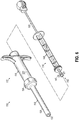
- the dispensing assembly 110 includes a syringe body 112 and a mixing and plunging assembly 114.
- the mixing and plunging assembly 114 is generally similar to the mixing and plunging assembly 14 discussed above with respect to the dispensing assembly 10.
- the syringe body 112 includes a barrel 116 and a dispensing tip 118, which is selectively attachable to and removable from the barrel 116.
- the barrel 116 includes a threaded portion 117 on an exterior surface 120 and near a distal end 122 of the barrel 116.
- the dispensing tip 118 is attachable to the barrel 116.
- the dispensing tip 118 includes an attachment portion 124 that is sized to be received over the distal end 122 of the barrel 116.
- the attachment portion 124 includes a radially interior threaded portion 126 that is configured to threadably mate with the threaded portion 117 of the barrel 116.
- the dispensing tip 118 further includes a dispensing tip tube 128 connected with the attachment portion 124.
- the dispensing tip tube 128 includes a dispensing passageway 130 that opens at a dispensing opening 132 for dispensing bone graft material.
- the dispensing tip tube 128 has a reduced diameter as compared with the barrel 116.
- the dispensing tip 118 may also be referred to as a cannulus or cannulus device, and can have any suitable length.
- the attachment portion 124 extends between a distal, or first, end 134 and an proximal, or second, end 136.
- the threaded portion 126 of the attachment portion 124 is generally between the ends 134, 136.
- the dispensing tip 118 is attached to the barrel 116 by threading the threaded portion 126 of the attachment portion 124 onto the threaded portion 117 of the barrel 116.
- the threaded portion 126 of the attachment portion 124 is threaded onto the threaded portion 117 of the barrel 116 until a distal end 122 of the barrel 116 is positioned generally near the distal end 134 of the attachment portion 124.
- the dispensing tip 118 includes one or more mixing element engagement tabs 140 for engaging with a mixing element 142 of the mixing and plunging assembly 114.
- the dispensing tip 118 includes a neck 144 radially inside the threaded portion 126 of the attachment portion 124.
- the neck 144 is configured to fit radially inside an interior surface 146 of the barrel 116 near the barrel distal end 122 when the dispensing tip 118 is attached to the barrel 116.
- two engagement tabs 140 extend from the neck 144 at diametrically opposed locations, and are configured to be situated within the barrel 116 near the distal end 122 thereof when the dispensing tip 118 is attached to the barrel 116.
- the engagement tabs 140 perform a similar function to the engagement tab 44 discussed above.
- the dispensing assembly 110 is used in a manner generally similar to the dispensing assembly 10.
- the mixing element 142 is generally near the barrel distal end 122.
- the mixing element engagement tabs 140 are positioned in the barrel 116 near the distal end 122.
- the mixer 150 of the mixing and plunging assembly 114 is moved so as to longitudinally align the engagement tabs 140 with the mixing element 142, and then the rod 152 of the mixer 150 is detached from the mixing element 142.
- the rod 152 is rotated relative to the syringe body 112 and the mixing element 142 comes into contacting engagement with one or more of the engagement tabs 140.
- the rod 152 is rotated relative to the syringe body 112 and the mixing element 142 comes into contacting engagement with one or more of the engagement tabs 140.
- Continued rotation of the rod 152 while the mixing element 142 is held still by the engagement tabs 140 causes the rod 152 to become detached from the mixing element 142, in a similar manner as discussed above.
- the rod 152 is detached from the mixing element 142, it is moved to dispense additional amounts of bone graft material from the syringe body 112 in a similar manner as discussed above.
- the rod 152 is moved into the dispensing passageway 130 of the dispensing tip 118, and bone graft material contained within the dispensing passageway 130 is pushed out of the dispensing opening 132.
- the dispensing tip 118 can be removed from the barrel 116 to introduce bone graft material, or components thereof, into the barrel 116.
- the dispensing tip 118 can be removed, and an adapter device (not shown) can be attached to the barrel 116 to facilitate the introduction of material into the barrel 116 in a generally known manner.
- FIGS. 9A and 9B additional features can be provided that relate to the connection between a mixing element and a rod.
- the attachment between the mixing elements 54, 142 and the rods 56, 152 is made through a threaded attachment.
- features can also be provided to create a snap-fit attachment between a mixing element and a rod, as shown with respect to the exemplary mixing element 160 and rod 162.
- the mixing element 160 includes a body 164 having a centrally located hub 166.
- a bore 168 extends through the hub 166 and includes a threaded portion 170.
- the bore 168 also includes a snap attachment portion 172 having an annular groove 174 for receiving a component on the rod 162.
- the rod 162 extends between a distal, or first, end 180, and an proximal, or second, end 182.
- the rod 162 includes a head 184 at the distal end 180.
- the rod 162 also includes a threaded portion 186 configured to be mated with the threaded portion 170 of the mixing element 160.
- the rod 162 further includes a snap attachment portion 188 situated generally between the head 184 and the threaded portion 186.
- the snap attachment portion 188 includes one or more nubs or protrusions 190 configured to be received in the annular groove 174 of the snap attachment portion 172 of the mixing element 160.
- the mixing element 160 and rod 162 are thus attachable by both a threaded attachment and a snap-fit attachment.
- the mixing element 160 is placed onto the rod 162 and moved toward the head 184 of the rod 162.
- the mixing element 160 is oriented so that the snap attachment portion 172 is positioned generally between the threaded portion 170 and the head 184 of the rod 162.
- the threaded portion 170 of the mixing element 160 is threaded onto the threaded portion 186 of the rod 162.
- the snap attachment portions 172, 188 become generally aligned, and the protrusions 190 extend into the annular groove 174.
- a snap-fit attachment is also formed between the mixing element 160 and the rod 162.
- the mixing element 160 is detached from the rod 162 in the reverse manner.
- the mixing element 160 is rotated relative to the rod 162 so that the threaded portion 170 on the mixing element 160 is threaded off of the threaded portion 186 of the rod 162.
- the protrusions 190 are moved away, and removed, from the annular groove 174, and the snap-fit attachment is overcome.
- the mixing element 160 and the rod 162 can include features designed to prevent material from being trapped between the mixing element 160 and the rod 162 are attached to one another.
- at least one or both of the mixing element 160 and the rod 162 can include vent grooves that allow material to escape being trapped.
- the mixing element 160 includes one or more longitudinally extending vent grooves that extend from the annular groove 174 to a forward portion of the hub 166.
- the rod 162 includes one or more longitudinally extending vent grooves that extend from the protrusions 190 to the distal end 180 of the rod 162. The grooves provide passageways for material to move in when the mixing element 160 is attached with the rod 162 in the manner discussed above. Thereby, the material is not trapped between the mixing element 160 and the rod 162 and can escape through the grooves.
- FIGS. 10A, 10B , 11A, and 11B additional features can be provided that relate to the connection between a rod and a plunger.
- the rods 56, 152 are entirely free to slidably move with respect to the plungers 52, 148.
- Features can be provided to limit the slidable movement of a rod with respect to a plunger.
- an attachment can be provided for limiting the movement of a rod with respect to a plunger.
- a threaded attachment can be provided to limit the slidable movement of the rod 200 relative to the plunger 202.
- the rod 200 includes an extended threaded portion 204 that is sized so that the threaded portion 204 extends beyond a mixing element 205 once the mixing element is attached to the threaded portion 204, such as in the manner discussed above with respect to the dispensing assembly 10.
- the threaded portion 204 that extends beyond the mixing element is used to attach the rod 200 with the plunger 202.
- the plunger 202 includes a plunger tip 206 having an opening 208 that receives the rod 200.
- the opening 208 includes a threaded portion 210 that is configured to mate with the threaded portion 204 of the rod 200.
- the rod 200 can thereby be selectively attached and detached from the plunger 202, wherein in the attached configuration, slidable movement of the rod 200 with respect to the plunger 202 is limited.
- the threaded portion 204 of the rod 200 is threaded into the threaded portion 210 of the opening 208 of the plunger tip 206 to put the rod 200 in the attached configuration.
- the threaded portion 204 of the rod 200 is threaded out of the threaded portion 210 of the opening 208 of the plunger tip 206 to put the rod 200 in the detached configuration.
- a snap-fit attachment can be provided to limit the slidable movement of a rod 220 relative to a plunger 222.
- the rod 220 includes one or more nubs or protrusions 224 on a shaft 226 of the rod 220.
- the rod 220 also includes a head 228 and a threaded portion 230, and the threaded portion 230 is generally positioned between the head 228 and the protrusions 224 on the shaft 226.
- the protrusions 224 are oriented on the shaft 226 so as to be accessible on the shaft 226 even once a mixing element 227 is attached to the threaded portion 230 of the rod 220, such as in a similar manner as discussed above with respect to the dispensing assembly 10.
- the protrusions 224 are configured to be received in a corresponding feature of the plunger 222.
- the plunger 222 includes a plunger tip 232 having an opening 234 that receives the rod 220.
- the opening 234 includes an annular groove 236 that is configured to receive the protrusions 224 of the rod 220.
- the rod 220 can thereby be selectively attached and detached from the plunger 222, wherein in the attached configuration, slidable movement of the rod 220 with respect to the plunger 222 is limited.
- the rod 220 is moved so that the protrusions 224 of the rod 220 are positioned in the groove 236 of the opening 234 of the plunger tip 232 to put the rod 220 in the attached configuration.
- the rod 220 is moved with respect to the plunger 222 so that the protrusions 224 are moved out of the groove 236 to put the rod 220 in the detached configuration.
- connection between a mixing element and a rod, and to limiting the slidable movement of a rod with respect to a plunger can be combined in any possible manner, including having none, any, or several of the above described features.
- an embodiment could be provided that includes both a snap-fit attachment between a mixing element and a rod, and either a threaded or a snap-fit attachment between a rod and a plunger.
- a mixing and plunging assembly 240 includes a mixer 242 and a plunger 244.
- the mixer 242 includes a rod 246 and a mixing element 248.
- the rod 246 includes an auger tip 250, a head 252, a threaded portion 254, and a shaft 256.
- the auger tip 250 is configured for engagement with material in a syringe body, such as bone graft material, or the components of bone graft material.
- the auger tip 250 extends forwardly from the head 252 so that it extends generally beyond the mixing element 248.
- the auger tip 250 has a generally conical shape with blades or flighting 258 extending therealong, and includes a generally pointed end 260. The pointed end 260 and the flighting 258 engage material when the mixer 242 is slidably and rotatably moved in a syringe body.
- the mixing element 248 includes a body 262 having a centrally located hub 264, which includes a threaded bore 266.
- the threaded bore 266 allows the mixing element 248 to be attached to the threaded portion 254 of the rod 246.
- the body 262 of the mixing element 248 also includes vanes 268 that extend outwardly from the hub 264, and the vanes 268 are configured for engaging material in a syringe body.
- each vane 268 includes a cutting surface 270.
- the body 262 extends generally between a distal, or first, end 272 and an proximal, or second, end 274.
- the vanes 268 extend generally in the direction from the distal end 272 toward the proximal end 274.
- the vanes 268 define leading edges 276 of the mixing element 248, and the cutting surfaces 270 are positioned generally on the leading edges 276.
- the leading edges 276 give the mixing element 282 a profile, or shape, that is configured to be generally complementary to the shape of a portion of the interior of a syringe body.
- a syringe body 280 includes a barrel 282 and a dispensing tip 284, which are connected by a barrel closure 286.
- the barrel closure 286 forms an angle relative to a longitudinal axis of the barrel 282 that is generally complementary with an angle formed by the vanes 268 and the leading edges 276 relative to the longitudinal axis of the barrel 272.
- the leading edges 276 of the mixing element 248 have a shape that is generally complementary with the interior shape of the syringe body 280 near the connection of the barrel 282 and the dispensing tip 284.
- the mixing element 248 when the mixing and plunging assembly 240 is moved to its forward-most location in the barrel 272, the mixing element 248 generally abuts the syringe body 280 near the connection of the barrel 282 and the dispensing tip 284. In particular, the leading edges 276 of the mixing element 248 will abut the barrel closure 286.
- Such a complementary shaped configuration between the mixing element 248 and the syringe body 280 encourages material in the barrel 282 to be moved into the dispensing tip 284, thereby minimizing the amount of material that would otherwise remain in the barrel 282 and be wasted.
- FIG. 13 includes an integrally formed barrel 282, dispensing tip 284, and barrel closure 286, similar to what is shown in FIGS. 1-4C . It will be appreciated, though, that a complementary shaped configuration between a mixing element and the interior shape of a syringe body is also applicable to a syringe body where the dispensing tip is selectively attachable to and removable from a barrel, such as shown in FIGS. 5-8B .
- FIGS. 14 and 15 alternative plunging tip configurations are shown.
- Some plunging tips such as those discussed above with respect to plungers 52 and 148 and shown in the related figures, have front surfaces that extend generally perpendicularly to the longitudinal axes of the plungers.
- FIGS. 14 and 15 show plunging tips having different configurations.
- FIG. 14 shows a plunging tip 290 that has a generally frusto-conically shaped body 292.
- the plunging tip 290 is configured to be incorporated in a plunger, and is also configured to have a shape that generally matches the shape of an associated mixing element 294.
- the mixing element 294 includes a centrally located hub 296 and vanes 298 extending outwardly therefrom.
- the vanes 298 are configured to engage material in a syringe body of a dispensing assembly, like the vanes of the mixing elements discussed above.
- the vanes 298 extend generally in the direction from a distal, or first, end 300 of the hub 296 toward an proximal, or second, end 302 of the hub 296. Thus, the vanes 298 extend generally at an angle with respect to a longitudinal axis of the hub 296.
- the hub 296 also includes nubs or protrusions 304 that are configured to be received in a corresponding feature of the plunging tip 290.
- the body 292 of the plunging tip 290 includes a bore 306 configured to partially receive the mixing element 294.
- An annular groove 308 is included in the bore 306 and is configured to receive the protrusions 304 of the mixing element 294.
- the body 292 includes a generally solid and sloped outer surface 310.
- the outer surface 310 is oriented relative to a longitudinal axis of the body 292 at approximately the same angle that the vanes 298 extend with respect to the longitudinal axis of the hub 296.
- the mixing element 294 and the plunging tip 290 are configured to be selectively coupled together.
- the hub 296 of the mixing element 294 is configured to be received in the bore 306 of the plunging tip 290 in the relative orientations shown in FIG. 14 .
- the mixing element 294 and the plunging tip 290 are brought together until the protrusions 304 on the hub 296 are received in the annular groove 308 of the plunging tip 290.
- the vanes 298 extend along the outer surface 310 of the plunging tip 290 in close relationship thereto.
- the shape of the mixing element 294 generally matches the shape of the plunging tip 290.
- the vanes 298 abut the outer surface 310 when the mixing element 294 and the plunging tip 290 are coupled together.
- the plunging tip 290 includes bores 312 that extend generally longitudinally through the body 292.
- the bores 312 are configured to allow air to escape past the plunging tip 290.
- the bores 312 intersect the outer surface 310 and extend through the body 292 to allow air to pass from the side of the plunging tip 290 having the outer surface 310 to the other side.
- a plunging tip 320 is shown and is associated with the same mixing element 294 discussed above and shown in FIG. 14 .
- the plunging tip 320 is generally similar to the plunging tip 290, but includes a body 322 having recesses or slots 324 for partially or completely receiving features of the mixing element 294.
- the slots 324 are configured to receive the vanes 298 of the mixing element 294.
- the mixing element 294 and the plunging tip 320 are configured to be selectively coupled together.
- the plunging tip has a bore 326 and the hub 296 of the mixing element 294 is configured to be received in the bore 296.
- the plunging tip 320 also includes an annular groove 328.
- the mixing element 294 and the plunging tip 320 are brought together so that the vanes 298 are received in the slots 324 and the protrusions 304 are received in the annular groove 328.
- the shape of the mixing element 294 generally matches the shape of the plunging tip 320, and the mixing element 294 partially fits within the body 322 of the plunging tip 320 when the mixing element 294 and plunging tip 320 are coupled together.
- the plunging tip 320 includes bores 330 that extend generally longitudinally through the body 322.
- the bores 330 serve a similar function as the bores 312 discussed above with respect to FIG. 14 . As shown, some of the bores 330 intersect the slots 324.
- a dispensing assembly can be provided that includes a syringe body and a plunging assembly.
- the syringe body includes a barrel and a dispensing tip.
- the plunging assembly is configured for coupling with the syringe body and includes a plunger and a rod.
- the plunger is configured to dispense material from the barrel through the dispensing tip.
- the rod is configured to be moved relative to the plunger and the syringe body into the dispensing tip to push material out of the dispensing tip.
- the plunger can include a passageway that receives the rod.
- the plunger and rod can be configured to selectively limit the slidable movement of the rod with respect to the plunger.
- the rod is detached from the plunger before the rod is pushed into the dispensing tip.
- the assemblies disclosed herein can be used for dispensing other types of materials than bone graft material, such as other biomaterials, or other materials, generally, that would benefit.
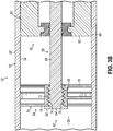
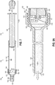
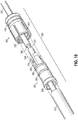
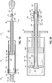
- FIGS. 16-21 illustrate a dispensing assembly 110' constructed according to another embodiment of the invention.
- new reference numerals are used to describe new elements of structure, while the same reference numerals are used to describe like structure previously shown and described in connection with FIGS. 5-8B .
- Those reference numerals having prime marks (') refer to elements of structure that correspond to like numbered, previously described elements in the embodiments of FIGS. 5-8B .
- the elements with reference numerals having prime marks will have slightly different form and/or function from the previously described elements and such differences will either be described hereinbelow or will be evident from a review of the drawings themselves. Generally, those elements that are identical to previously described structure will not be discussed hereinbelow, but the previous discussion may be referred to instead.
- connection is made at a proximal location on the assembly 110' as opposed to being made at the distal end, i.e., at the mixing element 142.
- the proximal location is preferably outside of the barrel 116.
- a connector assembly 350 is used to connect the mixer rod 152' for a translational and rotational movement with the mixing element 142 via a hollow shaft 352.
- the connector assembly 350 is used to ensure that the mixer rod 152' will travel back and forth with the hollow shaft 352 as the mixing element 142 is translated linearly within the syringe barrel 116 as shown in FIG. 20 .
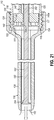
- keys 354 are formed at the distal end of the mixer rod 152' and are received within key ways 356 at the distal end of the hollow shaft 352.
- the distal end of the hollow shaft 352 is rigidly coupled to the mixing element 142.
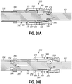
- the proximally located connector assembly 350 is actuated to release the mixing rod 152' from its connection to the hollow shaft 352.
- the connector assembly 350 includes a first connecting element 360 and a second connecting element 362.
- the first connecting element 360 is movable in a direction proximally along the second connecting element 362 and includes slots 364 for providing flexibility.
- the second connecting element 362 has a distal end 366 rigidly secured to the hollow shaft 352.
- the distal end 366 of the second connecting element 362 may be epoxied or otherwise rigidly adhered to the proximal end of the hollow shaft 352, while the proximal end 368 of the second connecting element 362 includes one or more projections 370 that are selectively retained within an annular groove 372 of the mixer rod 152'.
- a detent 378 moves from a first annular groove or recess 380 to a second, more proximally located annular groove or recess 382. This then prevents a proximal portion 384 of the first connecting element 360 from retaining the snap connection ends or projections 370 within the annular groove 372 and the mixer rod 152' may be pushed distally as illustrated in FIG. 20B while the first connecting element 360 is pulled proximally.
Landscapes
- Health & Medical Sciences (AREA)
- Chemical & Material Sciences (AREA)
- Chemical Kinetics & Catalysis (AREA)
- Life Sciences & Earth Sciences (AREA)
- Orthopedic Medicine & Surgery (AREA)
- Surgery (AREA)
- Engineering & Computer Science (AREA)
- Veterinary Medicine (AREA)
- General Health & Medical Sciences (AREA)
- Public Health (AREA)
- Animal Behavior & Ethology (AREA)
- Biomedical Technology (AREA)
- Molecular Biology (AREA)
- Medical Informatics (AREA)
- Heart & Thoracic Surgery (AREA)
- Nuclear Medicine, Radiotherapy & Molecular Imaging (AREA)
- Mechanical Engineering (AREA)
- Surgical Instruments (AREA)
- Prostheses (AREA)
- Dental Tools And Instruments Or Auxiliary Dental Instruments (AREA)
- Coating Apparatus (AREA)
- Pharmacology & Pharmacy (AREA)
Claims (15)
- Ensemble distributeur, comprenant un corps de seringue (12, 112, 280) ayant un cylindre (16, 116, 282) et une pointe de distribution (18, 118, 284), et un ensemble mélangeur et plongeur (14, 114, 240) configuré pour s'accoupler au corps de seringue (12, 112, 280) et comprenant un mélangeur (50, 242) et un piston (52, 148, 148', 202, 222, 244), le mélangeur (50, 242) étant configuré pour mélanger une matière dans le cylindre (16, 116, 282) et ayant une tige (56, 152, 152', 162, 200, 220, 246) et un élément mélangeur (54, 142, 160, 205, 248, 294) connecté à la tige (56, 152, 152', 162, 200, 220, 246), le piston (52, 148, 148', 202, 222, 244) étant configuré pour distribuer une matière du cylindre (16, 116, 282) à travers la pointe de distribution (18, 118, 284), caractérisé en ce que l'élément mélangeur (54, 142, 160, 205, 248, 294) est connecté d'une manière détachable à la tige (56, 152, 152', 162, 200, 220, 246) et la tige (56, 152, 152', 162, 200, 220, 246) est configurée pour être détachée de l'élément mélangeur (54, 142, 160, 205, 248, 294) et utilisée pour pousser la matière hors de la pointe de distribution (18, 118, 284).
- Ensemble distributeur selon la revendication 1, dans lequel la tige (56, 152, 152', 162, 200, 220, 246) comprend une extrémité distale et l'élément mélangeur (54, 142, 160, 205, 248, 294) est connecté d'une manière détachable à la tige (56, 152, 152', 162, 200, 220, 246) à l'extrémité distale.
- Ensemble distributeur selon la revendication 1, dans lequel la tige (162) comprend en outre une saillie (190) et l'élément mélangeur (160) comprend une rainure (174) configurée pour recevoir la saillie (190) afin de créer une fixation à emboîtement instantané entre la tige (162) et l'élément mélangeur (160).
- Ensemble distributeur selon la revendication 3, dans lequel au moins l'un d'entre l'élément mélangeur (160) et la tige (162) comprend une rainure pour empêcher de la matière d'être piégée entre l'élément mélangeur (160) et la tige (162).
- Ensemble distributeur selon la revendication 1, dans lequel la tige (202, 220) et le piston (204, 222) sont configurés pour limiter sélectivement un mouvement de glissement de la tige (202, 220) par rapport au piston (204, 222).
- Ensemble distributeur selon la revendication 5, dans lequel la tige (202, 220) comprend une première partie de connexion (204, 224) et le piston (204, 220) comprend une deuxième partie de connexion (210, 236) et la première et la deuxième partie de connexion peuvent être engagées et désengagées pour permettre à la tige et au piston d'être connectés et déconnectés.
- Ensemble distributeur selon la revendication 6, dans lequel la première partie de connexion comprend une saillie (224) et la deuxième partie de connexion comprend une rainure (236) configurée pour recevoir la saillie (224) afin de former une fixation à emboîtement instantané entre la tige (220) et le piston (222).
- Ensemble distributeur selon la revendication 6, dans lequel la première partie de connexion comprend une première partie filetée (204) et la deuxième partie de connexion comprend une deuxième partie filetée (210).
- Ensemble distributeur selon la revendication 1, dans lequel la tige (246) comprend une pointe à vrille (250) configurée pour engager une matière dans le corps de seringue (280).
- Ensemble distributeur selon la revendication 1, dans lequel l'élément mélangeur (248) comprend une surface coupante (270) configurée pour engager une matière dans le corps de seringue (280).
- Ensemble distributeur selon la revendication 1, dans lequel l'élément mélangeur (248) a une forme qui est généralement complémentaire à la forme d'un intérieur du corps de seringue (280) près de la pointe de distribution (284).
- Ensemble distributeur selon la revendication 1, dans lequel la tige (152') comprend une partie située à l'extérieur du corps de seringue (112) lorsque le mélangeur est accouplé au corps de seringue (112) avec l'élément mélangeur (142) positionné à l'intérieur du cylindre de seringue (112), et comprenant en outre un ensemble connecteur (350) situé à l'extérieur du corps de seringue (112) et capable d'être actionné sélectivement pour connecter et déconnecter la tige (152') et l'élément mélangeur (142).
- Ensemble distributeur selon la revendication 12, dans lequel le mélangeur comprend en outre un arbre creux (352) recevant la tige (152') et ayant une extrémité proximale et une extrémité distale, dans lequel l'élément mélangeur (142) est rigidement accouplé à l'extrémité distale et une partie de l'ensemble connecteur (350) est accouplée à l'extrémité proximale.
- Ensemble distributeur selon la revendication 13, dans lequel l'ensemble connecteur (350) comprend en outre un premier élément de connexion (360) et un deuxième élément de connexion (362), dans lequel le premier et le deuxième élément de connexion (360, 362) sont déplaçables l'un par rapport à l'autre entre une première et une deuxième position, dans lequel la tige (152') peut être utilisée pour faire tourner et déplacer l'élément mélangeur (142) lorsque le premier et le deuxième élément de connexion (360, 362) sont dans la première position et la tige (152') peut être déplacée par rapport à l'élément mélangeur (142) pour pousser ainsi la matière hors de la pointe de distribution lorsque le premier et le deuxième élément de connexion (360, 362) sont dans la deuxième position.
- Procédé de distribution de matière dans des buts autres que le traitement par chirurgie ou thérapie en utilisant un ensemble distributeur ayant un corps de seringue (12, 112, 280) et un ensemble mélangeur et plongeur (14, 114, 240), comprenant :déplacer un piston (52, 148, 148', 202, 222, 244) de l'ensemble mélangeur et plongeur (14, 114, 240) pour faire avancer une matière d'un cylindre (16, 116, 282) du corps de seringue (12, 112, 280) à travers une pointe de distribution (18, 118, 284) du corps de seringue (12, 112, 280) et hors d'une ouverture de la pointe de distribution du corps de seringue (12, 112, 280), détacher un élément mélangeur (54, 142, 160, 205, 248, 294) d'une tige (56, 152, 152', 162, 200, 220, 246) de l'ensemble mélangeur et plongeur (14, 114, 240), etdéplacer la tige (56, 152, 152', 162, 200, 220, 246) dans la pointe de distribution pour faire avancer une matière dans la pointe de distribution (18, 118, 284) hors de l'ouverture de la pointe de distribution.
Applications Claiming Priority (3)
| Application Number | Priority Date | Filing Date | Title |
|---|---|---|---|
| US201361838588P | 2013-06-24 | 2013-06-24 | |
| US14/311,945 US9456861B2 (en) | 2013-06-24 | 2014-06-23 | Dispensing assembly having mixing and plunging assembly, and related methods |
| PCT/US2014/043774 WO2014209940A1 (fr) | 2013-06-24 | 2014-06-24 | Ensemble de distribution ayant un ensemble de mélange et d'immersion et procédés associés |
Publications (2)
| Publication Number | Publication Date |
|---|---|
| EP3013263A1 EP3013263A1 (fr) | 2016-05-04 |
| EP3013263B1 true EP3013263B1 (fr) | 2017-08-23 |
Family
ID=52111494
Family Applications (1)
| Application Number | Title | Priority Date | Filing Date |
|---|---|---|---|
| EP14739646.9A Not-in-force EP3013263B1 (fr) | 2013-06-24 | 2014-06-24 | Ensemble de distribution ayant un ensemble de mélange et d'immersion et procédés associés |
Country Status (6)
| Country | Link |
|---|---|
| US (1) | US9456861B2 (fr) |
| EP (1) | EP3013263B1 (fr) |
| CN (1) | CN105338915B (fr) |
| CA (1) | CA2913591C (fr) |
| ES (1) | ES2645720T3 (fr) |
| WO (1) | WO2014209940A1 (fr) |
Families Citing this family (23)
| Publication number | Priority date | Publication date | Assignee | Title |
|---|---|---|---|---|
| CH708236A1 (de) * | 2013-06-18 | 2014-12-31 | Medmix Systems Ag | Misch- und Austragsvorrichtung mit Gewindespindel. |
| CN104688321B (zh) * | 2015-03-12 | 2017-03-01 | 艾科美医疗器械(深圳)有限公司 | 带搅拌和灌注功能的一体式骨水泥灌注器 |
| US11160595B2 (en) | 2015-04-15 | 2021-11-02 | Celgentek Limited | System, device and method for delivery of biomaterials for fracture fixation |
| CN105147384B (zh) * | 2015-07-30 | 2017-06-13 | 苏州爱得科技发展股份有限公司 | 骨水泥搅拌推注系统 |
| IL242924A0 (en) * | 2015-12-03 | 2016-04-21 | Omrix Biopharmaceuticals Ltd | Syringe system for storing and mixing two ingredients |
| CN109640851B (zh) * | 2016-06-03 | 2021-09-03 | 美敦力控股有限责任公司 | 分配系统和方法 |
| US11324673B2 (en) | 2016-11-18 | 2022-05-10 | Miraki Innovation Think Tank Llc | Cosmetic appearance of skin |
| IT201700010432A1 (it) * | 2017-01-31 | 2018-07-31 | Accademind S R L | Dispositivo di iniezione di cemento osseo |
| EP3606456A4 (fr) | 2017-04-05 | 2021-01-13 | Miraki Innovation Think Tank LLC | Confinement de suspension épaisse froide |
| SG11201909303TA (en) | 2017-04-05 | 2019-11-28 | Miraki Innovation Think Tank Llc | Point of delivery cold slurry generation |
| EP3661660A4 (fr) | 2017-08-04 | 2021-05-19 | Mark Robert Towler | Dispositif de stockage, mélange et distribution |
| US10500342B2 (en) * | 2017-08-21 | 2019-12-10 | Miraki Innovation Think Tank Llc | Cold slurry syringe |
| CN109395620A (zh) * | 2018-10-29 | 2019-03-01 | 北京航天新风机械设备有限责任公司 | 一种用于小剂量粘稠液体混合的一次性工具 |
| CN110152923B (zh) * | 2019-04-28 | 2020-12-11 | 沪东中华造船(集团)有限公司 | 一种环氧树脂涂胶机用静态混合器的清洗方法 |
| CN111482125B (zh) * | 2020-05-06 | 2022-03-11 | 山东大学齐鲁医院 | 一种口腔临床印模材料调和与挤出装置 |
| CN111468030B (zh) * | 2020-05-06 | 2022-03-11 | 山东大学齐鲁医院 | 一种带有开放式搅拌腔的口腔临床印模材料调和设备 |
| US11679002B2 (en) * | 2020-06-11 | 2023-06-20 | Orthofix Us Llc | Bone graft material loading assembly and associated devices, systems, and methods |
| USD1078042S1 (en) | 2020-07-02 | 2025-06-03 | Kenvue Brands Llc | Optical device with an alignment tab |
| WO2022006369A1 (fr) | 2020-07-02 | 2022-01-06 | Johnson & Johnson Consumer Inc. | Systèmes, procédés et appareils de fixation d'un otoscope |
| CN112603519B (zh) * | 2020-12-11 | 2022-02-15 | 南京佗道医疗科技有限公司 | 一种推注搅拌装置 |
| US11241330B1 (en) * | 2021-04-02 | 2022-02-08 | Brixton Biosciences, Inc. | Apparatus for creation of injectable slurry |
| DE102023113068B4 (de) * | 2023-05-17 | 2024-12-24 | Karl Storz Se & Co. Kg | Medizinischer Applikator und Verfahren zum Beladen eines medizinischen Applikators |
| US20250295523A1 (en) * | 2024-03-20 | 2025-09-25 | Alcon Inc. | Systems and methods for delivering a retinal patch |
Family Cites Families (12)
| Publication number | Priority date | Publication date | Assignee | Title |
|---|---|---|---|---|
| WO1999049818A1 (fr) | 1998-03-30 | 1999-10-07 | Marchosky J Alexander | Systeme prothetique |
| GB2338428A (en) | 1998-06-19 | 1999-12-22 | David Grant | A syringe with an agitator whose shaft passes through a slidable dispensing plunger |
| US20040267272A1 (en) | 2003-05-12 | 2004-12-30 | Henniges Bruce D | Bone cement mixing and delivery system |
| US7524103B2 (en) | 2003-11-18 | 2009-04-28 | Boston Scientific Scimed, Inc. | Apparatus for mixing and dispensing a multi-component bone cement |
| EP1903961B1 (fr) * | 2005-07-07 | 2012-05-16 | Crosstrees Medical, Inc. | Dispositif d'administration de materiaux de remplissage de vide osseux |
| US20070093759A1 (en) * | 2005-09-26 | 2007-04-26 | Isotis Orthobiologics, Inc. | High viscosity material delivery system |
| DE102007026034B4 (de) * | 2007-06-04 | 2016-03-03 | Aap Biomaterials Gmbh | Verfahren zum Mischen von Mischgut mit einer Misch- und Applikationsvorrichtung |
| US7879002B2 (en) * | 2007-10-31 | 2011-02-01 | Ultradent Products, Inc. | Mixing device including a plunging mixing member for use with a syringe |
| US8167835B2 (en) | 2008-02-28 | 2012-05-01 | Medmix Systems Ag | Single chamber device for drawing in and dispensing components |
| CH702757A1 (de) | 2010-02-22 | 2011-08-31 | Medmix Systems Ag | Spritzenartige Mischvorrichtung mit distal bedienbarem Mischelement. |
| JP2014030436A (ja) | 2010-11-19 | 2014-02-20 | Terumo Corp | 薬剤注入具 |
| CH705193A1 (de) | 2011-06-22 | 2012-12-31 | Medmix Systems Ag | Vorrichtung zum blasenarmen Mischen und Austragen eines Produkts. |
-
2014
- 2014-06-23 US US14/311,945 patent/US9456861B2/en active Active
- 2014-06-24 ES ES14739646.9T patent/ES2645720T3/es active Active
- 2014-06-24 WO PCT/US2014/043774 patent/WO2014209940A1/fr not_active Ceased
- 2014-06-24 EP EP14739646.9A patent/EP3013263B1/fr not_active Not-in-force
- 2014-06-24 CN CN201480036165.2A patent/CN105338915B/zh not_active Expired - Fee Related
- 2014-06-24 CA CA2913591A patent/CA2913591C/fr active Active
Non-Patent Citations (1)
| Title |
|---|
| None * |
Also Published As
| Publication number | Publication date |
|---|---|
| WO2014209940A1 (fr) | 2014-12-31 |
| CA2913591A1 (fr) | 2014-12-31 |
| CN105338915B (zh) | 2019-08-20 |
| EP3013263A1 (fr) | 2016-05-04 |
| CA2913591C (fr) | 2021-08-03 |
| CN105338915A (zh) | 2016-02-17 |
| US9456861B2 (en) | 2016-10-04 |
| US20140378937A1 (en) | 2014-12-25 |
| ES2645720T3 (es) | 2017-12-07 |
Similar Documents
| Publication | Publication Date | Title |
|---|---|---|
| CA2913591C (fr) | Ensemble de distribution ayant un ensemble de melange et d'immersion et procedes associes | |
| US10966770B2 (en) | Assembly for dispensing biomaterial, plunger therefor, and related methods | |
| EP1424945B1 (fr) | Seringue filetee pour injection de substitut osseux | |
| US20100298832A1 (en) | Steerable curvable vertebroplasty drill | |
| JP6391739B2 (ja) | ペースト状セメント成分用の収納混合システムおよびそのための方法 | |
| US20030014056A1 (en) | Delivery device for bone cement | |
| JP6514279B2 (ja) | 圧力リリーフのための三方弁を有する骨セメントアプリケータ | |
| JP6563970B2 (ja) | ペースト状セメント成分用の収納混合システムおよびそのための方法 | |
| US11109906B2 (en) | Bone cement applicator with retractable mixing rod and method for production of a bone cement | |
| WO2019023805A1 (fr) | Dispositif de stockage, mélange et distribution | |
| US20050113762A1 (en) | Minimally invasive high viscosity material delivery system | |
| CA2982665C (fr) | Systeme, dispositif et procede d'administration de biomateriaux pour fixation de fracture | |
| US11679002B2 (en) | Bone graft material loading assembly and associated devices, systems, and methods | |
| US7833216B2 (en) | Fluid plunger adhesive dispenser | |
| US20260137399A1 (en) | Bone graft delivery devices and method | |
| WO2011083357A1 (fr) | Dispositifs, procédés et systèmes pour mélanger et distribuer une matière liquide | |
| HK40113862A (zh) | 使用液压力将能够流动的治疗组合物递送到外科手术部位的系统、装置和方法 | |
| HK1151706B (en) | Steerable vertebroplasty system with cavity creation element | |
| HK1151706A1 (en) | Steerable vertebroplasty system with cavity creation element |
Legal Events
| Date | Code | Title | Description |
|---|---|---|---|
| PUAI | Public reference made under article 153(3) epc to a published international application that has entered the european phase |
Free format text: ORIGINAL CODE: 0009012 |
|
| 17P | Request for examination filed |
Effective date: 20160119 |
|
| AK | Designated contracting states |
Kind code of ref document: A1 Designated state(s): AL AT BE BG CH CY CZ DE DK EE ES FI FR GB GR HR HU IE IS IT LI LT LU LV MC MK MT NL NO PL PT RO RS SE SI SK SM TR |
|
| AX | Request for extension of the european patent |
Extension state: BA ME |
|
| RIN1 | Information on inventor provided before grant (corrected) |
Inventor name: ANDERSON, BENJAMIN, B. Inventor name: LOU, HUADONG Inventor name: HOOGENAKKER, JON, E. Inventor name: STEVENSON, MARK Inventor name: GEPPERT, KEVIN, C. Inventor name: RZESZUTEK, ZACHARY |
|
| DAX | Request for extension of the european patent (deleted) | ||
| GRAP | Despatch of communication of intention to grant a patent |
Free format text: ORIGINAL CODE: EPIDOSNIGR1 |
|
| INTG | Intention to grant announced |
Effective date: 20170313 |
|
| GRAS | Grant fee paid |
Free format text: ORIGINAL CODE: EPIDOSNIGR3 |
|
| GRAA | (expected) grant |
Free format text: ORIGINAL CODE: 0009210 |
|
| AK | Designated contracting states |
Kind code of ref document: B1 Designated state(s): AL AT BE BG CH CY CZ DE DK EE ES FI FR GB GR HR HU IE IS IT LI LT LU LV MC MK MT NL NO PL PT RO RS SE SI SK SM TR |
|
| REG | Reference to a national code |
Ref country code: GB Ref legal event code: FG4D |
|
| REG | Reference to a national code |
Ref country code: CH Ref legal event code: EP |
|
| REG | Reference to a national code |
Ref country code: AT Ref legal event code: REF Ref document number: 920451 Country of ref document: AT Kind code of ref document: T Effective date: 20170915 |
|
| REG | Reference to a national code |
Ref country code: IE Ref legal event code: FG4D |
|
| REG | Reference to a national code |
Ref country code: DE Ref legal event code: R096 Ref document number: 602014013533 Country of ref document: DE |
|
| REG | Reference to a national code |
Ref country code: ES Ref legal event code: FG2A Ref document number: 2645720 Country of ref document: ES Kind code of ref document: T3 Effective date: 20171207 |
|
| REG | Reference to a national code |
Ref country code: NL Ref legal event code: MP Effective date: 20170823 |
|
| REG | Reference to a national code |
Ref country code: LT Ref legal event code: MG4D |
|
| REG | Reference to a national code |
Ref country code: AT Ref legal event code: MK05 Ref document number: 920451 Country of ref document: AT Kind code of ref document: T Effective date: 20170823 |
|
| PG25 | Lapsed in a contracting state [announced via postgrant information from national office to epo] |
Ref country code: HR Free format text: LAPSE BECAUSE OF FAILURE TO SUBMIT A TRANSLATION OF THE DESCRIPTION OR TO PAY THE FEE WITHIN THE PRESCRIBED TIME-LIMIT Effective date: 20170823 Ref country code: LT Free format text: LAPSE BECAUSE OF FAILURE TO SUBMIT A TRANSLATION OF THE DESCRIPTION OR TO PAY THE FEE WITHIN THE PRESCRIBED TIME-LIMIT Effective date: 20170823 Ref country code: NO Free format text: LAPSE BECAUSE OF FAILURE TO SUBMIT A TRANSLATION OF THE DESCRIPTION OR TO PAY THE FEE WITHIN THE PRESCRIBED TIME-LIMIT Effective date: 20171123 Ref country code: SE Free format text: LAPSE BECAUSE OF FAILURE TO SUBMIT A TRANSLATION OF THE DESCRIPTION OR TO PAY THE FEE WITHIN THE PRESCRIBED TIME-LIMIT Effective date: 20170823 Ref country code: NL Free format text: LAPSE BECAUSE OF FAILURE TO SUBMIT A TRANSLATION OF THE DESCRIPTION OR TO PAY THE FEE WITHIN THE PRESCRIBED TIME-LIMIT Effective date: 20170823 Ref country code: FI Free format text: LAPSE BECAUSE OF FAILURE TO SUBMIT A TRANSLATION OF THE DESCRIPTION OR TO PAY THE FEE WITHIN THE PRESCRIBED TIME-LIMIT Effective date: 20170823 Ref country code: AT Free format text: LAPSE BECAUSE OF FAILURE TO SUBMIT A TRANSLATION OF THE DESCRIPTION OR TO PAY THE FEE WITHIN THE PRESCRIBED TIME-LIMIT Effective date: 20170823 |
|
| PG25 | Lapsed in a contracting state [announced via postgrant information from national office to epo] |
Ref country code: PL Free format text: LAPSE BECAUSE OF FAILURE TO SUBMIT A TRANSLATION OF THE DESCRIPTION OR TO PAY THE FEE WITHIN THE PRESCRIBED TIME-LIMIT Effective date: 20170823 Ref country code: BG Free format text: LAPSE BECAUSE OF FAILURE TO SUBMIT A TRANSLATION OF THE DESCRIPTION OR TO PAY THE FEE WITHIN THE PRESCRIBED TIME-LIMIT Effective date: 20171123 Ref country code: LV Free format text: LAPSE BECAUSE OF FAILURE TO SUBMIT A TRANSLATION OF THE DESCRIPTION OR TO PAY THE FEE WITHIN THE PRESCRIBED TIME-LIMIT Effective date: 20170823 Ref country code: GR Free format text: LAPSE BECAUSE OF FAILURE TO SUBMIT A TRANSLATION OF THE DESCRIPTION OR TO PAY THE FEE WITHIN THE PRESCRIBED TIME-LIMIT Effective date: 20171124 Ref country code: IS Free format text: LAPSE BECAUSE OF FAILURE TO SUBMIT A TRANSLATION OF THE DESCRIPTION OR TO PAY THE FEE WITHIN THE PRESCRIBED TIME-LIMIT Effective date: 20171223 Ref country code: RS Free format text: LAPSE BECAUSE OF FAILURE TO SUBMIT A TRANSLATION OF THE DESCRIPTION OR TO PAY THE FEE WITHIN THE PRESCRIBED TIME-LIMIT Effective date: 20170823 |
|
| PG25 | Lapsed in a contracting state [announced via postgrant information from national office to epo] |
Ref country code: CZ Free format text: LAPSE BECAUSE OF FAILURE TO SUBMIT A TRANSLATION OF THE DESCRIPTION OR TO PAY THE FEE WITHIN THE PRESCRIBED TIME-LIMIT Effective date: 20170823 Ref country code: DK Free format text: LAPSE BECAUSE OF FAILURE TO SUBMIT A TRANSLATION OF THE DESCRIPTION OR TO PAY THE FEE WITHIN THE PRESCRIBED TIME-LIMIT Effective date: 20170823 Ref country code: RO Free format text: LAPSE BECAUSE OF FAILURE TO SUBMIT A TRANSLATION OF THE DESCRIPTION OR TO PAY THE FEE WITHIN THE PRESCRIBED TIME-LIMIT Effective date: 20170823 |
|
| REG | Reference to a national code |
Ref country code: DE Ref legal event code: R097 Ref document number: 602014013533 Country of ref document: DE |
|
| PG25 | Lapsed in a contracting state [announced via postgrant information from national office to epo] |
Ref country code: EE Free format text: LAPSE BECAUSE OF FAILURE TO SUBMIT A TRANSLATION OF THE DESCRIPTION OR TO PAY THE FEE WITHIN THE PRESCRIBED TIME-LIMIT Effective date: 20170823 Ref country code: SK Free format text: LAPSE BECAUSE OF FAILURE TO SUBMIT A TRANSLATION OF THE DESCRIPTION OR TO PAY THE FEE WITHIN THE PRESCRIBED TIME-LIMIT Effective date: 20170823 Ref country code: SM Free format text: LAPSE BECAUSE OF FAILURE TO SUBMIT A TRANSLATION OF THE DESCRIPTION OR TO PAY THE FEE WITHIN THE PRESCRIBED TIME-LIMIT Effective date: 20170823 |
|
| REG | Reference to a national code |
Ref country code: FR Ref legal event code: PLFP Year of fee payment: 5 |
|
| PLBE | No opposition filed within time limit |
Free format text: ORIGINAL CODE: 0009261 |
|
| STAA | Information on the status of an ep patent application or granted ep patent |
Free format text: STATUS: NO OPPOSITION FILED WITHIN TIME LIMIT |
|
| 26N | No opposition filed |
Effective date: 20180524 |
|
| PG25 | Lapsed in a contracting state [announced via postgrant information from national office to epo] |
Ref country code: SI Free format text: LAPSE BECAUSE OF FAILURE TO SUBMIT A TRANSLATION OF THE DESCRIPTION OR TO PAY THE FEE WITHIN THE PRESCRIBED TIME-LIMIT Effective date: 20170823 |
|
| REG | Reference to a national code |
Ref country code: CH Ref legal event code: PL |
|
| REG | Reference to a national code |
Ref country code: BE Ref legal event code: MM Effective date: 20180630 |
|
| REG | Reference to a national code |
Ref country code: IE Ref legal event code: MM4A |
|
| PG25 | Lapsed in a contracting state [announced via postgrant information from national office to epo] |
Ref country code: LU Free format text: LAPSE BECAUSE OF NON-PAYMENT OF DUE FEES Effective date: 20180624 Ref country code: MC Free format text: LAPSE BECAUSE OF FAILURE TO SUBMIT A TRANSLATION OF THE DESCRIPTION OR TO PAY THE FEE WITHIN THE PRESCRIBED TIME-LIMIT Effective date: 20170823 |
|
| PG25 | Lapsed in a contracting state [announced via postgrant information from national office to epo] |
Ref country code: LI Free format text: LAPSE BECAUSE OF NON-PAYMENT OF DUE FEES Effective date: 20180630 Ref country code: CH Free format text: LAPSE BECAUSE OF NON-PAYMENT OF DUE FEES Effective date: 20180630 Ref country code: IE Free format text: LAPSE BECAUSE OF NON-PAYMENT OF DUE FEES Effective date: 20180624 |
|
| PG25 | Lapsed in a contracting state [announced via postgrant information from national office to epo] |
Ref country code: BE Free format text: LAPSE BECAUSE OF NON-PAYMENT OF DUE FEES Effective date: 20180630 |
|
| PGFP | Annual fee paid to national office [announced via postgrant information from national office to epo] |
Ref country code: DE Payment date: 20190619 Year of fee payment: 6 |
|
| PG25 | Lapsed in a contracting state [announced via postgrant information from national office to epo] |
Ref country code: MT Free format text: LAPSE BECAUSE OF NON-PAYMENT OF DUE FEES Effective date: 20180624 |
|
| PG25 | Lapsed in a contracting state [announced via postgrant information from national office to epo] |
Ref country code: TR Free format text: LAPSE BECAUSE OF FAILURE TO SUBMIT A TRANSLATION OF THE DESCRIPTION OR TO PAY THE FEE WITHIN THE PRESCRIBED TIME-LIMIT Effective date: 20170823 |
|
| PG25 | Lapsed in a contracting state [announced via postgrant information from national office to epo] |
Ref country code: PT Free format text: LAPSE BECAUSE OF FAILURE TO SUBMIT A TRANSLATION OF THE DESCRIPTION OR TO PAY THE FEE WITHIN THE PRESCRIBED TIME-LIMIT Effective date: 20170823 |
|
| PG25 | Lapsed in a contracting state [announced via postgrant information from national office to epo] |
Ref country code: CY Free format text: LAPSE BECAUSE OF FAILURE TO SUBMIT A TRANSLATION OF THE DESCRIPTION OR TO PAY THE FEE WITHIN THE PRESCRIBED TIME-LIMIT Effective date: 20170823 Ref country code: HU Free format text: LAPSE BECAUSE OF FAILURE TO SUBMIT A TRANSLATION OF THE DESCRIPTION OR TO PAY THE FEE WITHIN THE PRESCRIBED TIME-LIMIT; INVALID AB INITIO Effective date: 20140624 Ref country code: MK Free format text: LAPSE BECAUSE OF NON-PAYMENT OF DUE FEES Effective date: 20170823 |
|
| PG25 | Lapsed in a contracting state [announced via postgrant information from national office to epo] |
Ref country code: AL Free format text: LAPSE BECAUSE OF FAILURE TO SUBMIT A TRANSLATION OF THE DESCRIPTION OR TO PAY THE FEE WITHIN THE PRESCRIBED TIME-LIMIT Effective date: 20170823 |
|
| REG | Reference to a national code |
Ref country code: DE Ref legal event code: R119 Ref document number: 602014013533 Country of ref document: DE |
|
| PG25 | Lapsed in a contracting state [announced via postgrant information from national office to epo] |
Ref country code: DE Free format text: LAPSE BECAUSE OF NON-PAYMENT OF DUE FEES Effective date: 20210101 |
|
| P01 | Opt-out of the competence of the unified patent court (upc) registered |
Effective date: 20230530 |
|
| PGFP | Annual fee paid to national office [announced via postgrant information from national office to epo] |
Ref country code: FR Payment date: 20230628 Year of fee payment: 10 |
|
| PGFP | Annual fee paid to national office [announced via postgrant information from national office to epo] |
Ref country code: IT Payment date: 20230623 Year of fee payment: 10 Ref country code: GB Payment date: 20230622 Year of fee payment: 10 Ref country code: ES Payment date: 20230829 Year of fee payment: 10 |
|
| GBPC | Gb: european patent ceased through non-payment of renewal fee |
Effective date: 20240624 |
|
| PG25 | Lapsed in a contracting state [announced via postgrant information from national office to epo] |
Ref country code: FR Free format text: LAPSE BECAUSE OF NON-PAYMENT OF DUE FEES Effective date: 20240630 |
|
| PG25 | Lapsed in a contracting state [announced via postgrant information from national office to epo] |
Ref country code: GB Free format text: LAPSE BECAUSE OF NON-PAYMENT OF DUE FEES Effective date: 20240624 Ref country code: IT Free format text: LAPSE BECAUSE OF NON-PAYMENT OF DUE FEES Effective date: 20240624 |
|
| REG | Reference to a national code |
Ref country code: ES Ref legal event code: FD2A Effective date: 20250801 |
|
| PG25 | Lapsed in a contracting state [announced via postgrant information from national office to epo] |
Ref country code: ES Free format text: LAPSE BECAUSE OF NON-PAYMENT OF DUE FEES Effective date: 20240625 |