EP3013600B1 - Agencement de fixation à verrouillage central pour roues composites - Google Patents
Agencement de fixation à verrouillage central pour roues composites Download PDFInfo
- Publication number
- EP3013600B1 EP3013600B1 EP14839900.9A EP14839900A EP3013600B1 EP 3013600 B1 EP3013600 B1 EP 3013600B1 EP 14839900 A EP14839900 A EP 14839900A EP 3013600 B1 EP3013600 B1 EP 3013600B1
- Authority
- EP
- European Patent Office
- Prior art keywords
- centre
- lock
- attachment
- fastener
- front element
- Prior art date
- Legal status (The legal status is an assumption and is not a legal conclusion. Google has not performed a legal analysis and makes no representation as to the accuracy of the status listed.)
- Active
Links
Images



Classifications
-
- B—PERFORMING OPERATIONS; TRANSPORTING
- B60—VEHICLES IN GENERAL
- B60B—VEHICLE WHEELS; CASTORS; AXLES FOR WHEELS OR CASTORS; INCREASING WHEEL ADHESION
- B60B3/00—Disc wheels, i.e. wheels with load-supporting disc body
- B60B3/14—Attaching disc body to hub ; Wheel adapters
- B60B3/142—Attaching disc body to hub ; Wheel adapters by central locking nut
-
- B—PERFORMING OPERATIONS; TRANSPORTING
- B60—VEHICLES IN GENERAL
- B60B—VEHICLE WHEELS; CASTORS; AXLES FOR WHEELS OR CASTORS; INCREASING WHEEL ADHESION
- B60B3/00—Disc wheels, i.e. wheels with load-supporting disc body
- B60B3/002—Disc wheels, i.e. wheels with load-supporting disc body characterised by the shape of the disc
- B60B3/004—Disc wheels, i.e. wheels with load-supporting disc body characterised by the shape of the disc in the hub section
-
- B—PERFORMING OPERATIONS; TRANSPORTING
- B60—VEHICLES IN GENERAL
- B60B—VEHICLE WHEELS; CASTORS; AXLES FOR WHEELS OR CASTORS; INCREASING WHEEL ADHESION
- B60B3/00—Disc wheels, i.e. wheels with load-supporting disc body
- B60B3/14—Attaching disc body to hub ; Wheel adapters
-
- B—PERFORMING OPERATIONS; TRANSPORTING
- B60—VEHICLES IN GENERAL
- B60B—VEHICLE WHEELS; CASTORS; AXLES FOR WHEELS OR CASTORS; INCREASING WHEEL ADHESION
- B60B3/00—Disc wheels, i.e. wheels with load-supporting disc body
- B60B3/14—Attaching disc body to hub ; Wheel adapters
- B60B3/16—Attaching disc body to hub ; Wheel adapters by bolts or the like
-
- B—PERFORMING OPERATIONS; TRANSPORTING
- B60—VEHICLES IN GENERAL
- B60B—VEHICLE WHEELS; CASTORS; AXLES FOR WHEELS OR CASTORS; INCREASING WHEEL ADHESION
- B60B3/00—Disc wheels, i.e. wheels with load-supporting disc body
- B60B3/14—Attaching disc body to hub ; Wheel adapters
- B60B3/16—Attaching disc body to hub ; Wheel adapters by bolts or the like
- B60B3/165—Attaching disc body to hub ; Wheel adapters by bolts or the like with locking devices for the fixing means, e.g. screw or nut covers
-
- B—PERFORMING OPERATIONS; TRANSPORTING
- B60—VEHICLES IN GENERAL
- B60B—VEHICLE WHEELS; CASTORS; AXLES FOR WHEELS OR CASTORS; INCREASING WHEEL ADHESION
- B60B5/00—Wheels, spokes, disc bodies, rims, hubs, wholly or predominantly made of non-metallic material
- B60B5/02—Wheels, spokes, disc bodies, rims, hubs, wholly or predominantly made of non-metallic material made of synthetic material
-
- B—PERFORMING OPERATIONS; TRANSPORTING
- B60—VEHICLES IN GENERAL
- B60B—VEHICLE WHEELS; CASTORS; AXLES FOR WHEELS OR CASTORS; INCREASING WHEEL ADHESION
- B60B2360/00—Materials; Physical forms thereof
- B60B2360/30—Synthetic materials
- B60B2360/34—Reinforced plastics
- B60B2360/341—Reinforced plastics with fibres
- B60B2360/3416—Carbone fibres
-
- B—PERFORMING OPERATIONS; TRANSPORTING
- B60—VEHICLES IN GENERAL
- B60B—VEHICLE WHEELS; CASTORS; AXLES FOR WHEELS OR CASTORS; INCREASING WHEEL ADHESION
- B60B2900/00—Purpose of invention
- B60B2900/30—Increase in
- B60B2900/311—Rigidity or stiffness
-
- B—PERFORMING OPERATIONS; TRANSPORTING
- B60—VEHICLES IN GENERAL
- B60B—VEHICLE WHEELS; CASTORS; AXLES FOR WHEELS OR CASTORS; INCREASING WHEEL ADHESION
- B60B2900/00—Purpose of invention
- B60B2900/30—Increase in
- B60B2900/325—Reliability
Definitions
- the present invention generally relates to a centre-lock arrangement for attaching one or more composite wheels to a mount.
- the invention is particularly applicable to attachment arrangements for carbon fibre wheels and it will be convenient to hereinafter disclose the invention in relation to that exemplary application.
- Attaching composite structures to other components or structures can be challenging.
- Composite structures such as carbon fibre components, are generally extremely strong and stiff in the fibre direction, but can have less stiffness and strength perpendicular to the fibre direction.
- Attachment holes for a bolted joint connection are generally formed perpendicular to the fibre direction. Compressive loads through a joint formed through such attachment holes will therefore be perpendicular to the fibres rather than aligned with them.
- the stiffness of the material perpendicular to the fibres is quite low. Consequently, a low clamping pressure is required between the head of a bolt/washer and a mount to which it is to be connected to avoid damage. High clamping pressures can damage composite material at or immediately adjacent a preformed attachment hole, causing delamination at or immediately adjacent the edge of that attachment hole. This makes it difficult to achieve a stiff joint with conventional attachment and fastening arrangements.
- a washer may be used to distribute the load over a greater area.
- conventional flat washers provide an uneven load distribution about the attachment aperture. In most cases, the load is greater in the region closer to the head of the bolt, thus creating an undesirable high compression zone close to the edge of the attachment hole.
- Special fastener combinations may therefore be used for composite structures.
- International Patent Application No. PCT/AU2012/000598 filed by the present Applicant describes an attachment arrangement for a multiple bolted joint composite wheel having attachment apertures arranged evenly in a radial orientation around the rotational axis of the wheel.
- the attachment arrangement includes a fastening washer having a base configured to face a surface of the composite wheel about the attachment aperture and a fastening side having an engagement surface configured to operatively engage a complementary portion of a fastening nut when the fastening nut is assembled on an elongate fastener element.
- the fastening arrangement also includes a sleeve configured to extend into an attachment aperture of the composite wheel and be received in a complementary shaped sleeve aperture located in the mount or in an element located adjacent the mount.
- a sleeve configured to extend into an attachment aperture of the composite wheel and be received in a complementary shaped sleeve aperture located in the mount or in an element located adjacent the mount.
- Each of the hub bolts in the JP and DE documents are used for mounting the wheel to the hub and for fixing the front plate and backing plate to the wheel; in the GB document the front and backing plate are bolted together, thus clamping the fibre wheel rim, whilst the wheel is mounted to rotate on a hollow shaft and axially fixed with an expanding-core fastener.
- a single central attachment feature is often used for high performance vehicles, particularly in racing applications. This is commonly referred to as a centre-lock attachment system.
- the attachment arrangement described in PCT/AU2012/000598 may not be ideally suited to a centre-lock attachment system as a scaled up version of this arrangement suitable for a centre-lock system may not effectively spread the clamping force away from the centre of the a centre-lock attachment aperture to a large enough contact area.
- a centre-lock form of this arrangement will therefore still provide an undesirable high compression zone close to the edge of the centre-lock attachment aperture of the composite wheel.
- the present invention provides a centre-lock attachment arrangement for use in attaching at least one composite wheel to a mount and comprising a centre-lock fastener and a centre-lock fastening nut which can be fastened on the centre-lock fastener, as claimed in independent claim 1.
- Preferred embodiments are defined in dependent claims.
- the composite wheel includes a central attachment area having a central attachment aperture through which the centre-lock fastener is inserted, and a plurality of fastener apertures annularly spaced around the attachment aperture thereof.
- the attachment arrangement includes a front element having an outer engagement surface which, in use, operatively engages the centre-lock fastening nut, and an inner engagement surface which, in use, operatively engages with the outer side of the central attachment area of the composite wheel.
- the front element also includes an attachment aperture through which the centre-lock fastener is inserted and a plurality of fastener apertures annularly spaced around the attachment aperture thereof. These fastener apertures are complementary to the fastener apertures of the central attachment area of the composite wheel.
- the attachment arrangement also includes a backing element having an outer engagement surface which, in use, faces, preferably operatively engages with, the mount, and an inner engagement surface which, in use, operatively engages with the inner side of the central attachment area of the composite wheel.
- the backing element also includes an attachment aperture through which the centre-lock fastener is inserted and a plurality of fastener apertures spaced apart around the attachment aperture thereof, said fastener apertures being complementary to the fastener apertures of the central attachment area of the composite wheel.
- the attachment arrangement further includes a plurality of elongate fasteners configured to be received through the aligned apertures of the front element and the backing element. In use, the elongate fasteners clamp the front element and the backing element over and around the central attachment area of the composite wheel.
- the central attachment area of a composite wheel is substantially sandwiched between the front element and the backing element when the attachment arrangement of the present invention is assembled on a composite wheel.
- the front element, the backing element and the cooperating elongate fasteners function to spread the clamping force of a centre-lock wheel mount over a large area within the attachment region, and more particularly away from the center and edges of the central attachment aperture of composite wheel. Therefore, when the composite wheel is attached to the mount, the combination of the centre-lock clamping force and the clamping force generated by the elongate fasteners provides an evenly distributed clamping pressure between the mating surfaces of the front element and the front face of the wheel. This ensures that the centre-lock arrangement between the wheel and mount performs with minimal to no loss of attachment system performance during vehicle operation.
- the distribution of clamping force between the front element and the backing element can be optimised by configuring the fastener apertures of the central attachment area, the front element and the backing element to be substantially evenly spaced apart, preferably evenly annularly spaced apart, around the respective attachment aperture.
- the clamping force of each individual elongate fastener therefore acts on a substantially equal area.
- An even clamping force and pressure between the front element, backing element and the attachment region of the composite wheel is preferably attained when, in use, the moment in the front element between a clamping force produced by a centre-lock fastening connection, and in particular the centre-lock fastening nut, engaging the front element and a clamping force of each of the individual elongate fasteners is substantially zero, and more preferably equal to zero.
- the spread of load away from the center and edges of the centre-lock aperture of the composite wheel is in part dependent on the radial distance the fastener apertures are spaced away from the attachment aperture (or the centre of the central attachment area of the composite wheel).
- the fastener apertures of the central attachment area, the front element and the backing element are therefore preferably radially spaced away from the center of the central attachment area of the composite wheel (being coaxial with the center of the composite wheel) by as great a radial spacing as can be accommodated for a particular design. In most designs, that radial spacing will be limited between the diameter of the attachment aperture of the composite wheel and by the size, preferably outer perimeter/ diameter, of the mount on which the backing element abuts.
- the central attachment aperture of the composite wheel is sized to fit a particular centre-locking system.
- the central attachment aperture is typically sized between 40 to 100 mm in diameter, preferably between 60 to 80 mm.
- the fastener apertures of the central attachment area, the front element and the backing element are therefore preferably radially spaced away from the annular edge of the respective attachment aperture as great a radial spacing that can be accommodated for a particular design.
- the fastener apertures of the central attachment area, the front element and the backing element are radially spaced away from the center of the central attachment area of the composite wheel between the annular center of an inner and outer diameter of the front element, and the outer diameter of the mount.
- the fastener apertures of the central attachment area, the front element and the backing element are therefore preferably radially spaced away from the center of the central attachment area of the composite wheel and more preferably close to the outer diameter of the mount.
- the function of the attachment arrangement can be enhanced by preloading the elongate fasteners when the arrangement is assembled on the composite wheel. Preloading the elongate fasteners creates a preload between the backing element and the front element during the assembly. Generating sufficient preload force in the elongate fasteners provides strong and reliable joints that do not loosen or break under normal loading conditions.
- the attachment apertures of each of the backing element, central attachment area of the composite wheel and the front element are configured to receive the centre-lock fastener along a fastening axis, which extends axially through the center of the central attachment aperture of the composite wheel.
- At least one of the front element or the backing element can further include a sleeve which extends axially relative to the fastening axis outwardly from the inner engagement surface about the attachment aperture of the respective front element or backing element.
- Each sleeve is preferably configured to extend into the attachment aperture of the composite wheel. The sleeve(s) function to distribute the load away from the centre of the attachment aperture of the composite wheel.
- the elongate fasteners can comprise any suitable interlocking fastening arrangement with a fastening nut or other interlocking recess.
- the elongate fasteners comprise a screw or bolt type fastener having a head and an elongate body attached to the head.
- the elongate fastener is designed to cooperate with a nut or interlocking recess which is formed in or operatively engages with the front element or the backing element.
- the head of the elongate fastener can be locked or otherwise secured to the front element or the backing element.
- the elongate body of each elongate fastener is inserted through the respective fastener apertures of the backing element, the attachment area of the composite wheel, and the front element.
- the distal end of the elongate fastener can be locked or otherwise secured in a nut or interlocking recess operatively engaged or formed in the other of the backing element or front element, thereby clamping the front element and the backing element together.
- the fastener apertures of the front element are configured to receive and fasten a distal end of a respective elongate fastener therein.
- the elongate fasteners preferably include an external threaded surface and the fastener apertures of the front element preferably include a complementary internal threaded bore.
- the fastener apertures of the front element can comprise blind bores or may comprise through bores.
- the elongate fasteners are operatively associated with the wheel mount preferably the drive system of a vehicle. This operative association preferably enables the elongate fasteners to function as torque transfer or drive pins for transferring torque from the wheel mount/ drive system to the composite wheel.
- the elongate fasteners form part of the drive pin arrangement attached to the wheel mount and/or drive arrangement of a vehicle. This allows the elongate fasteners to be used as drive pins.
- the elongate fasteners are configured to operatively engage with the drive pins of a vehicle, for example, through a cooperatively configured connector arrangement or the like.
- the inner engagement surfaces of each of the front element and the backing element may comprise part of, or the entirety of an inner side of the respective element.
- the inner engagement surfaces of each of the front element and the backing element are preferably configured to transfer compression force from the elongate fasteners and centre-lock fastener and centre-lock nut through to composite wheel.
- the inner engagement surfaces can therefore have a complementary configuration to the surface of the composite wheel it faces. More preferably, the inner engagement surfaces have complementary contours and features to the surface of the composite wheel about the attachment aperture.
- the inner engagement surfaces can include a substantially flat engagement surface or surfaces. These surfaces can be configured to abut the surface of the composite wheel about the attachment aperture.
- the front element functions to transfer clamping force from the centre-lock nut across the attachment area of the composite wheel clamped between the front element and the backing element.
- the front element includes a nut recess configured to receive the fastening nut.
- the nut recess can have any suitable shape and configuration (cross-sectional shape relative to the fastening axis or similar) which can receive the front element.
- the recess is preferably a complementary shape to the front element. Suitable cross-sectional shapes include polygonal shapes such as triangular, square, pentagonal, hexagonal, or the like.
- the recess has a circular cross-sectional shape.
- the nut recess is formed in an outer sleeve which extends outwardly relative to the outer engagement surface of the front element.
- the front element can include in some embodiments one or more radial reinforcement elements, preferably ribs, extending from the nut recess to the location of each of the fastener apertures in the front element.
- the ribs assist in transferring forces from the sleeve to the body of the front element and through to the elongate fasteners.
- the mount can be a support, backing, setting, or the like, on or in which something is, or is to be, mounted or fixed.
- the mount would be a wheel mount (or wheel hub) for the composite wheel.
- the mount can have any suitable centre-lock configuration.
- the mount typically includes a centre-lock fastener extending outwardly from the mounting surface.
- the mount further includes a plurality of annularly spaced apart torque transmission members, typically pins or rods, annularly spaced around the centre-lock fastener.
- the attachment area of the composite wheel and backing element include a plurality of mount apertures annularly spaced around the attachment aperture thereof.
- the mount apertures are provided to receive a torque transmission feature associated with the mount.
- the centre-lock attachment arrangement further includes a centre-lock fastener and a centre-lock fastening nut which can be fastened on the centre-lock fastener.
- the centre-lock fastener and fastening nut cooperating with the elongate fasteners to cooperatively clamp the front element and the backing element over and around the central attachment area of the composite wheel.
- the configuration of the composite wheel used with the attachment arrangement of the present invention can be designed to accommodate the attachment arrangement.
- the composite wheel may include a recess in the central attachment area of the composite wheel in which the front element can be located.
- the recess can be any suitable shape which can receive the front element.
- the recess is preferably a complementary shape to the front element. In some embodiments, the recess is circular.
- the composite wheel fastened using the attachment arrangement of the present invention can be any composite material in which compression joint damage can occur, for example, a fibre reinforced composite such as, but not limited to, a carbon fibre composite material or carbon/epoxy composite. It should however be understood that other types of composite materials other than carbon fibre and epoxy resin could be used in the composite wheels of the present invention which use the same joint.
- One preferred application is for attaching the composite wheel to a wheel mount, and more preferably one or more fibre composite wheels, for example carbon composite fibre wheels.
- the composite wheels are preferably mountable to a vehicle such as an automobile, truck or the like.
- the attachment arrangement of the present invention enables the composite wheel to have an extremely stiff fastening to the mount relative to the fastening nut without damaging the composite wheel.
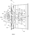
- Figure 1 and 2 illustrate a centre-lock carbon fibre composite wheel 100 which can be attached to a wheel mount or wheel hub (not illustrated) utilising a centre-lock wheel fastening system 100A which includes a centre-lock attachment arrangement 101 according to a preferred embodiment of the present invention.
- the illustrated centre-lock wheel fastening system 100A includes a central centre-lock fastening mount 103 providing a circular hub which includes a centre-lock stud 103A which receives a centre-lock fastening nut 105 over its distal end to lock a wheel received on the fastening fastener/ stud 103A onto that fastening fastener/ stud 103A.
- the centre-lock fastening stud 103A is typically an elongate externally threaded pin or rod having a complementary thread to a threaded internal bore 105A ( Figure 2 ) of the centre-lock fastening nut 105.
- the centre-lock wheel fastening system 100A often includes a plurality of torque transfer or drive pins or rods (not illustrated) radially spaced away from and annularly spaced apart around the central fastening stud 103A.
- the illustrated composite wheel 100 is a one piece carbon fibre wheel.
- An example of one suitable composite wheel 100 is a carbon fibre wheel developed by the Applicant formed as a one-piece body. The general process of manufacture of this composite wheel 100 is described in International Patent Publication WO2010/025495A1 .
- the illustrated composite wheel 100 includes two main sections:
- the spokes 108 comprise elongate arms connected to the hub 106 at one end and the rim portion 102 at another end.
- the hub 106 comprises a circular recessed area in the center of the face portion 104, having a central attachment area 109 having a central attachment aperture 110 through which the centre-lock fastener (not illustrated) of the wheel mount 103 is inserted when the wheel 100 is mounted on the wheel mount 103.
- the central attachment aperture 110 of the composite wheel 100 is sized to fit a particular centre-locking system.
- the central attachment aperture 110 is typically sized between 40 to 100 mm in diameter, preferably between 60 to 80 mm.
- the composite wheel 100, central attachment area 109 and central attachment aperture 110 all include a co-axial centre having central axis X-X extending axially through that centre.
- the hub 106 also includes ten annularly spaced apart torque transfer apertures 112 configured to receive complementary aligned torque transfer pins/rods (not illustrated) fixed to or otherwise spaced around the wheel mount 103.
- the torque transfer apertures 112 are preferably radially spaced as far away from the central axis X-X of the composite wheel as allowed by the design of the vehicle hub.
- the hub 106 also includes ten annularly spaced apart fastener apertures 114 also annularly spaced around the attachment aperture 110 thereof.
- the fastener apertures 114 are radially positioned further away from the central axis X-X relative to the torque transfer apertures 112. As best shown in Figure 1 , the fastener apertures 114 are also positioned annularly between each torque transfer aperture 112.
- the fastener apertures 114 are therefore preferably radially spaced away as from the central axis X-X of the composite wheel 100 as far as is allowed by the design of the vehicle hub.
- the illustrated attachment arrangement 101 comprises an interengageable set comprising a front element 116, a backing element 118 and a plurality (in the illustrated embodiment ten) fastening bolts 120.
- the illustrated front element 116 comprises a circular body having an outer side 122 which faces outwardly relative to the composite wheel 100 when assembled thereon and an inner side 123 which faces towards and abuts the composite wheel 100 when assembled thereon.
- An attachment aperture 121 is provided in the center of the front element 116 configured to align with the attachment aperture 110 of the composite wheel 100 when assembled thereon, and configured to receive the centre-lock stud 103A.
- the outer side 122 includes a circular nut recess 124 ( Figures 1 and 2 ) configured to receive the fastening nut 105.
- the nut recess 124 is formed in an outer sleeve 125, and as best illustrated in Figure 2 includes an outer engagement surface 126 which, in use, operatively engages the centre-lock fastening nut 105.
- the outer engagement surface 126 includes an annular chamfer configured to engage and cooperate with a complementary taper or chamfer located on an engagement face 107 of the fastening nut 105.
- the inner side 123 provides an inner engagement surface which, in use, operatively engages with the outer side 128 of the central attachment area 109 of the composite wheel 100.
- the inner side 123 also includes a plurality of fastener apertures 130 annularly spaced around the attachment aperture 121 thereof.
- the fastener apertures 130 of the front element 116 are complementarily configured and aligned with the fastener apertures 114 of the central attachment area 109 of the composite wheel 100.
- the illustrated fastener apertures 130 of the front element 116 comprise internally threaded blind bores configured to receive and fasten a distal end of a respective fastening bolt 120 therein.
- the fastening bolts 120 include an external threaded surface 135.
- the fastener apertures 130 of the front element 116 include a complementary internally threaded bore.
- the inner side 123 of the front element 116 also includes a cylindrical sleeve 136 which extends axially relative to the central axis X-X outwardly from the inner side 123 about the attachment aperture 121 of the front element 116.
- the sleeve 136 is configured to extend into the attachment aperture 110 of the composite wheel 100. Whilst not significant in the illustrated embodiment, in other embodiments, the sleeve 136 can function to distribute the load away from the centre of the attachment aperture 110 of the composite wheel 100.
- the outer side 122 and inner side 123 of the front element 116 include a plurality of radial reinforcement ribs 138, 139, extending from the nut recess 124 to the location of each of the fastener apertures 130 on the outer side 122 of the front element 116 and extending from the sleeve 136 to the location of each of the fastener apertures 130 on the inner side 122 of the front element 116.
- the ribs 138, 139 assist in transferring forces from the sleeve 136 to the body of the front element 116 and through to the elongate fasteners 120.
- the ribs 139 of the inner side 123 of the front element 116 define recesses in the inner side 123 of the front element 116 which can receive the distal end of torque transfer rods inserted through the respective torque transfer apertures 112, 150 of the central attachment area 109 of the composite wheel 100 and the backing element 118.
- the illustrated backing element 118 comprises a ring or annulus shaped plate having an outer engagement surface 142 which, in use, operatively engages with the mount, and an inner engagement surface 144 which, in use, operatively engages with the inner side 145 ( Figure 2 ) of the central attachment area 109 of the composite wheel 100.
- An attachment aperture 146 is provided in the center of the backing element 118 configured to align with the attachment aperture 110 of the composite wheel 100 when assembled thereon, and configured to receive the centre-lock fastener 103A.
- a plurality of fastener apertures 148 are provided annularly spaced around the attachment aperture 146 thereof.
- the fastener apertures 148 of the backing element 118 are also complementarily configured and aligned with the fastener apertures 114 of the central attachment area 109 of the composite wheel 100.
- Each fastener aperture 148 of the backing element 118 is configured to receive and substantially recess a head 154 of each respective fastening bolt 120.
- the bore of each fastener aperture 148 is stepped to provide an internal step surface 149 configured to engage the head 154 of an elongate fastener 120 received within the fastener aperture 148 and retain the head 154 within the fastener aperture 148.
- the backing element 118 includes a plurality of torque transfer apertures 150 are also provided annularly spaced around the attachment aperture 146 thereof.
- the torque transfer apertures 150 of the backing element 118 are complementarily configured and aligned with the torque transfer apertures 112 of the central attachment area 109 of the composite wheel 100.
- the backing element 118 also includes a cylindrical sleeve 152 which extends axially relative to the central axis X-X outwardly from the inner engagement surface 144 of the backing element 118 about the attachment aperture 146 of the backing element 118.
- the sleeve 152 is configured to extend into the attachment aperture 109 of the composite wheel 100.
- the sleeve 152 of the backing element 118 can in other embodiments function to distribute the load away from the centre of the attachment aperture 110 of the composite wheel 100. In such embodiments, the sleeve 152 would assist in pressure distribution using interference or the like with the engaged surface.
- the front element sleeve 136 and backing element sleeve 152 are configured to overlap, to form a continuous sleeve within the central attachment aperture 110 when the attachment arrangement 101 is assembled on a composite wheel 100.
- the front element sleeve 136 is cooperatively received within the backing element sleeve 152.
- the sleeves 136, 152 are designed to move freely when overlapping.
- the fastening bolts 120 of the illustrated attachment arrangement 101 comprise a bolt type fastener configured to be received through the respectively aligned fastener apertures 130, 114 and 149 of the front element 116, the central attachment area 109 and the backing element 118. In use, the fastening bolts 120 clamp the front element 116 and the backing element 118 over and around the central attachment area 109 of the composite wheel 100.
- the illustrated fastening bolts 120 include a cylindrical head 154 and elongate body 155 attached to the head 154.
- each fastening bolts 120 include a hexagonal recess 158 (best shown in Figure 3 ) which can be used to rotate the fastening bolts 120, for example when inserted within a fastener apertures 148, 114, and 130.
- the elongate body 155 includes an external threaded surface 135 as previously noted.
- the fastening bolts 120 are designed to cooperate with the internal thread of the fastening aperture 130 of the front element 116.
- the elongate body 155 of the fastening bolts 120 is inserted through the respective fastener apertures 148, 114, 130 of the backing element 118, the attachment area 109 of the composite wheel 100 and the front element 116.
- the distal end 156 of the fastening bolts 120 can be locked or otherwise secured in the fastening aperture 130 of the front element 116, thereby clamping the front element 116 and the backing element 118 together.
- the fastening bolts 120 are preferably preloaded when the arrangement is assembled on the composite wheel 100 thereby creating a preload between the backing element 118 and the front element 116 during the assembly.
- the respective attachment apertures 146, 110, 121 and fastener apertures 148, 114, 130 of each of the backing element 118, the central attachment area 109 of the composite wheel 100 and the front element 116 are aligned, and the central attachment area 109 of the composite wheel 100 is substantially sandwiched between the front element 116 and the backing element 119.
- the fastening bolts 120 are then inserted into the respectively aligned fastener apertures 148, 114, 130, and are tightened including a preloading procedure.
- the centre-lock stud/fastener 103A is inserted fully through the respective aligned attachment apertures 146, 110, 121 and the centre-lock fastening nut 105 is tightened over the distal end of the centre-lock stud 103A of the centre-lock mount 103.
- the fastening nut 105 is tightened around the distal end of the centre-lock stud 103A, the chamfer of the outer engagement surface 126 engages with the cooperating chamfer 107 of the fastening nut 105.
- the taper of these surfaces directs the clamping force of this engagement at an angle away from the attachment aperture 110 of the composite wheel 100.
- Tightening the fastening nut 105 clamps the front element 116 and the backing element 119 around the overlapping sections of the central attachment area 109 around or proximate the attachment aperture 110 of the composite wheel 100.
- the centre-lock fastening nut 105, the centre-lock stud 103A and mount 103 and the elongate fasteners 120 therefore each cooperatively clamp the central attachment area 109 between the front element 118 and the backing element 119.
- This co-operative clamping functions to spread the clamping force over a large area within the central attachment area 109, and more particularly away from the center and edges of the attachment aperture 110 of the composite wheel 100.
- an even clamping pressure is preferably attained when, in use, the moment M in the front element between a clamping force F C produced by the centre-lock fastening nut 105 engaging the front element 116 and a clamping force F B of each of the individual elongate fasteners 120 is substantially zero.
- clamping force F B acts at a distance of x B from the center of moment of the two forces
- clamping force F C acts at a distance of X C from the center of moment of the two forces.
- moment F B x X B should equal F C x X C to produce a zero moment in the front element 116.
- the fastener apertures 148, 114, 130 of each of the backing element 118, the central attachment area 109 of the composite wheel 100 and the front element 116 are therefore preferably radially spaced away from the center X-X of the central attachment area 109 of the composite wheel 100 by as great a radial spacing that can be accommodated for a particular design. In most designs, that radial spacing will be constrained between the diameter A of the attachment aperture 110 of the composite wheel 100 and the outer diameter C of the mount 103 on which the backing element 118 abuts.
- the fastener apertures 148, 114, 130 are preferably radially spaced away from the center X of the central attachment area 109 of the composite wheel 100 close to the outer diameter C of the mount 103. As shown in Figure 5 , the centre line Y-Y of the fastener apertures 148, 114, 130 is positioned a short distance D away from the outer diameter C of the mount 103.
- the illustrated embodiment could be modified so that the elongate fasteners form part of the drive pin arrangement attached to the wheel mount and/or drive arrangement of a vehicle.
- This allows the elongate fasteners to be used as drive pins if the vehicle system and wheel system, particularly where the composite wheel and vehicle have been designed concurrently.
- the elongate fasteners are configured to operatively engage with the drive pins of a vehicle, for example, through a cooperatively configured connector arrangement or the like.
- separate apertures would not be required for the torque transfer apertures and fastening apertures of the composite wheel and centre-lock attachment arrangement. In this embodiment, these only a single set of apertures could be used for both.
- the illustrated attachment arrangement 101 including the front element 116, the backing element 118 and the fastening bolts 120 can be formed from any suitable material.
- that material is stiffer than the composite material of the composite wheel, more preferably has a higher compression modulus.
- Suitable materials include aluminium, iron, steel, titanium, magnesium and alloys thereof.
Landscapes
- Engineering & Computer Science (AREA)
- Mechanical Engineering (AREA)
- Chemical & Material Sciences (AREA)
- Materials Engineering (AREA)
- Connection Of Plates (AREA)
- Tires In General (AREA)
Claims (15)
- Agencement d'attache à verrouillage central (101) destiné à être utilisé pour attacher au moins une roue composite (100) sur une monture (103), dans lequel l'agencement d'attache à verrouillage central (101) inclut un moyen de fixation à verrouillage central (103A) et un écrou de fixation à verrouillage central (105) qui peut être fixé sur le moyen de fixation à verrouillage central (103A), et dans lequel la roue composite (100) inclut une zone d'attache centrale (109) ayant une ouverture d'attache centrale (110) à travers laquelle le moyen de fixation à verrouillage central (103A) est inséré, et une pluralité d'ouvertures de fixation (114) espacées de manière annulaire autour de l'ouverture d'attache (110) de celle-ci, dans lequel l'agencement d'attache inclut en outre :un élément avant (116) incluant une surface d'engagement extérieure (126) qui, en utilisation, engage fonctionnellement l'écrou de fixation à verrouillage central (105), et une surface d'engagement intérieure qui, en utilisation, engage fonctionnellement le côté extérieur (128) de la zone d'attache centrale (109) de la roue composite (100), l'élément avant (116) incluant une ouverture d'attache (121) à travers laquelle le moyen de fixation à verrouillage central (103A) est inséré et une pluralité d'ouvertures de fixation (130) espacées de manière annulaire autour de l'ouverture d'attache (121) de celui-ci, lesdites ouvertures de fixation (130) étant complémentaires des ouvertures de fixation (114) de la zone d'attache centrale (109) de la roue composite (100) ;un élément de doublage (118) incluant une surface d'engagement extérieure (142) qui, en utilisation, est face à la monture (103), et une surface d'engagement intérieure (144) qui, en utilisation, engage fonctionnellement le côté intérieur (145) de la zone d'attache centrale (109) de la roue composite (100), l'élément de doublage (118) incluant une ouverture d'attache (146) à travers laquelle le moyen de fixation à verrouillage central (103A) est inséré et une pluralité d'ouvertures de fixation (148) espacées autour de l'ouverture d'attache (146) de celui-ci, lesdites ouvertures de fixation (148) étant complémentaires des ouvertures de fixation (114) de la zone d'attache centrale (109) de la roue composite (100) ; etune pluralité d'éléments de fixation allongés (120) configurés pour être reçus à travers les ouvertures alignées (130, 114 et 148) de l'élément avant (116) et de l'élément de doublage (118) qui, en utilisation, pincent l'élément avant (116) et l'élément de doublage (118) par-dessus et autour de la zone d'attache centrale (109) de la roue composite (100),dans lequel, en utilisation, le moyen de fixation à verrouillage central (103A) et l'écrou de fixation à verrouillage central (105) coopèrent avec les éléments de fixation allongés (120) pour pincer en coopération l'élément avant (116) et l'élément de doublage (118) par-dessus et autour de la zone d'attache centrale (109) de la roue composite (100).
- Agencement d'attache à verrouillage central (101) selon la revendication 1, dans lequel les ouvertures de fixation (130, 114 et 148) de la zone d'attache centrale (109), de l'élément avant (116) et de l'élément de doublage (118) sont espacées de manière sensiblement régulière autour de l'ouverture d'attache respective (110, 121, 146).
- Agencement d'attache à verrouillage central (101) selon l'une quelconque des revendications précédentes, dans lequel, en utilisation, le couple dans l'élément avant (116) entre une force de pincement produite par l'écrou de fixation à verrouillage central (105) engageant l'élément avant (116) et une force de pincement de chacun des éléments de fixation allongés individuels (120) est sensiblement nul.
- Agencement d'attache à verrouillage central (101) selon l'une quelconque des revendications précédentes, dans lequel la monture (103) qui engage l'élément de doublage (118) inclut un diamètre extérieur et les ouvertures de fixation (130, 114 et 148) de la zone d'attache centrale (109), de l'élément avant (116) et de l'élément de doublage (118) sont espacées radialement en éloignement du centre (X) de la zone d'attache centrale (109) de la roue composite d'un diamètre intérieur et extérieur de l'élément avant (116), et le diamètre extérieur (C) de la monture (103).
- Agencement d'attache à verrouillage central (101) selon l'une quelconque des revendications précédentes, dans lequel l'ouverture d'attache (130, 114 et 148) inclut un axe de fixation (X-X) le long duquel l'élément de fixation (103A) s'étend lorsqu'il est inséré dans l'ouverture d'attache (130, 114 et 148), et dans lequel au moins un élément parmi l'élément avant (116) ou l'élément de doublage (118) inclut en outre un manchon (136) qui s'étend axialement par rapport à l'axe de fixation (X-X) vers l'extérieur depuis la surface d'engagement intérieure autour de l'ouverture d'attache (121, 146) de l'élément avant (116) ou de l'élément de doublage (118) respectif, le manchon (136) étant configuré pour s'étendre dans l'ouverture d'attache (121) de la roue composite (100).
- Agencement d'attache à verrouillage central (101) selon l'une quelconque des revendications précédentes, dans lequel les ouvertures de fixation (130) de l'élément avant (116) sont configurées pour recevoir et pour fixer une extrémité distale d'un élément de fixation allongé (120) respectif dans celle-ci.
- Agencement d'attache à verrouillage central (101) selon l'une quelconque des revendications précédentes, dans lequel les ouvertures de fixation (130) de l'élément avant (116) comprennent des perçages borgnes.
- Agencement d'attache à verrouillage central (101) selon l'une quelconque des revendications précédentes, dans lequel chaque élément de fixation allongé (120) inclut une tête (154) et un corps allongé (155) attaché à la tête (154), et dans lequel les ouvertures de fixation (148) de l'élément de doublage (118) comprennent un perçage en gradins pour présenter une surface de gradin interne (149) configurée pour engager une surface d'arrêt de la tête (154) d'un élément de fixation allongé (120) reçu à l'intérieur de l'ouverture de fixation (148) et pour retenir la tête (154) à l'intérieur de l'ouverture de fixation (148).
- Agencement d'attache à verrouillage central (101) selon l'une quelconque des revendications précédentes, dans lequel les éléments de fixation allongés (120) incluent une surface extérieure filetée (135) et les ouvertures de fixation (130) de l'élément avant (116) incluent un perçage interne taraudé complémentaire.
- Agencement d'attache à verrouillage central (101) selon l'une quelconque des revendications précédentes, dans lequel les éléments de fixation allongés (120) sont fonctionnellement associés à la monture de roue (103), de préférence au système d'entraînement d'un véhicule.
- Agencement d'attache à verrouillage central (101) selon l'une quelconque des revendications précédentes, dans lequel la surface d'engagement intérieure (144) d'au moins un élément parmi l'élément avant (116) ou l'élément de doublage (118) inclut une surface d'engagement sensiblement plane configurée pour venir en butée sur la surface de la roue composite (100) autour de l'ouverture d'attache (110).
- Agencement d'attache à verrouillage central (101) selon l'une quelconque des revendications précédentes, dans lequel l'élément avant (116) inclut un évidement pour écrou (124) configuré pour recevoir l'écrou de fixation (105), et l'élément avant (116) inclut un élément de renfort radial (138, 139), de préférence des nervures, s'étendant depuis l'évidement pour écrou (124) jusqu'à l'emplacement de chacune des ouvertures de fixation (148) dans l'élément avant (116).
- Agencement d'attache à verrouillage central (101) selon l'une quelconque des revendications précédentes, dans lequel la zone d'attache (109) de la roue composite (100) et de l'élément de doublage (118) inclut une pluralité d'ouvertures de montage (112, 150) espacées de manière annulaire autour de l'ouverture d'attache respective (110, 146) de celle-ci.
- Agencement d'attache à verrouillage central (101) selon la revendication 13, dans lequel l'élément avant (116) inclut un évidement aligné de manière complémentaire avec les ouvertures de montage (112, 150) de la zone d'attache (109) et de l'élément de doublage (118).
- Agencement d'attache à verrouillage central (101) selon l'une quelconque des revendications précédentes, dans lequel la roue composite (100) comprend une roue en matériau composite à base de fibres, de préférence une roue composite à fibres de carbone.
Applications Claiming Priority (2)
| Application Number | Priority Date | Filing Date | Title |
|---|---|---|---|
| AU2013903314A AU2013903314A0 (en) | 2013-08-30 | Centre-lock attachment arrangement for composite wheels | |
| PCT/AU2014/000324 WO2015027271A1 (fr) | 2013-08-30 | 2014-03-27 | Agencement de fixation à verrouillage central pour roues composites |
Publications (3)
| Publication Number | Publication Date |
|---|---|
| EP3013600A1 EP3013600A1 (fr) | 2016-05-04 |
| EP3013600A4 EP3013600A4 (fr) | 2017-08-30 |
| EP3013600B1 true EP3013600B1 (fr) | 2018-10-24 |
Family
ID=52585289
Family Applications (1)
| Application Number | Title | Priority Date | Filing Date |
|---|---|---|---|
| EP14839900.9A Active EP3013600B1 (fr) | 2013-08-30 | 2014-03-27 | Agencement de fixation à verrouillage central pour roues composites |
Country Status (6)
| Country | Link |
|---|---|
| US (1) | US10112436B2 (fr) |
| EP (1) | EP3013600B1 (fr) |
| JP (1) | JP6421186B2 (fr) |
| CN (1) | CN105517812B (fr) |
| ES (1) | ES2707381T3 (fr) |
| WO (1) | WO2015027271A1 (fr) |
Families Citing this family (19)
| Publication number | Priority date | Publication date | Assignee | Title |
|---|---|---|---|---|
| GB2541498B8 (en) | 2016-06-14 | 2017-11-29 | Dymag Group Ltd | Rim for a wheel |
| US10744817B2 (en) * | 2017-01-04 | 2020-08-18 | Revel Wheels, LLC | Centerlock wheel assembly |
| CN106926635A (zh) * | 2017-03-24 | 2017-07-07 | 厦门集质复材科技有限公司 | 一种碳纤维轮毂辐条 |
| CN106985605A (zh) * | 2017-03-24 | 2017-07-28 | 厦门集质复材科技有限公司 | 一种碳纤维轮毂 |
| DE112018005823A5 (de) * | 2017-11-13 | 2020-09-10 | ThyssenKrupp Carbon Components GmbH | Fahrzeugradanordnung und verfahren zur herstellung einer fahrzeugradanordnung |
| USD877015S1 (en) * | 2017-11-17 | 2020-03-03 | Revel Wheels, L.L.C. | Centerlock wheel assembly |
| CN108100857B (zh) * | 2017-12-28 | 2024-02-02 | 江苏宝宸净化设备有限公司 | 一种核电厂混凝土桶型处置容器的专用吊具 |
| CA185738S (en) * | 2018-07-26 | 2019-12-27 | Ferrari Spa | Car |
| CN110872934B (zh) * | 2018-08-30 | 2021-08-03 | 中国石油天然气股份有限公司 | 抽油机转轮锁定装置和抽油机转轮锁定方法 |
| US12168369B2 (en) | 2018-10-24 | 2024-12-17 | Mubea Carbo Tech Gmbh | Wheel |
| USD923546S1 (en) * | 2018-11-09 | 2021-06-29 | Ferrari S.P.A. | Vehicle wheel rim |
| WO2020187892A1 (fr) | 2019-03-20 | 2020-09-24 | Mubea Carbo Tech Gmbh | Roue pour véhicule |
| TWD208053S (zh) * | 2019-05-14 | 2020-11-01 | 德商英諾托克有限公司 | 馬達外殼 |
| US11850889B1 (en) * | 2019-05-31 | 2023-12-26 | Tiger Tool International Incorporated | Hub cap systems and methods for vehicle wheels |
| US12128708B2 (en) * | 2020-05-05 | 2024-10-29 | Wheelsafe Technology, Inc. | Bell lock safety restraint for wheel assemblies |
| USD944174S1 (en) | 2020-08-17 | 2022-02-22 | O.E. Wheel Distributors, LLC | Wheel rim |
| TWI739607B (zh) * | 2020-09-23 | 2021-09-11 | 芫鴻科技工業有限公司 | 用於固定齒輪盤之螺柱結構 |
| DE102021208800A1 (de) * | 2021-08-11 | 2023-02-16 | Klaus Wohlfarth | Felgensystem und Anordnung mit einem Felgensystem |
| US12083826B2 (en) * | 2021-12-17 | 2024-09-10 | Nissan North America, Inc. | Vehicle wheel assembly |
Family Cites Families (24)
| Publication number | Priority date | Publication date | Assignee | Title |
|---|---|---|---|---|
| GB1571825A (en) * | 1977-05-31 | 1980-07-23 | Langley M E | Inflatable tyre covers |
| JPS5957204U (ja) * | 1982-10-09 | 1984-04-14 | 本田技研工業株式会社 | 車輌用ホイ−ル |
| US4478458A (en) * | 1982-11-02 | 1984-10-23 | Mcgard, Inc. | Locking and anti-loosening construction for vehicle rim |
| JPS59118502A (ja) * | 1982-12-24 | 1984-07-09 | Hayashi Lacing:Kk | 自動車用ホイ−ルの着脱機構 |
| JPS63180401A (ja) | 1987-01-19 | 1988-07-25 | Mitsui Eng & Shipbuild Co Ltd | アクテイブ防振機能を有する切削工具 |
| JPS63180401U (fr) * | 1987-05-15 | 1988-11-22 | ||
| DE9311280U1 (de) * | 1992-01-31 | 1993-10-28 | Siteco S.r.l., Pordenone | Fahrzeugrad |
| IT1258062B (it) * | 1992-01-31 | 1996-02-20 | Ruota per autoveicoli | |
| DE69411175T2 (de) * | 1993-08-18 | 1999-02-11 | Toora S.R.L., San Paolo D'argon | Leichtmetallanordnung für kraftfahrzeuge |
| US5492391A (en) * | 1993-10-21 | 1996-02-20 | Snook; Steven J. | Oval spline-drive wheel and adapter |
| JP2523256Y2 (ja) * | 1993-11-08 | 1997-01-22 | 将一 林 | 自動車用ホイールの取付装置 |
| US5584537A (en) * | 1995-05-11 | 1996-12-17 | Miansian; James K. | Wheel spinner nut adapter |
| US5820224A (en) * | 1997-02-19 | 1998-10-13 | L.A. Wire Wheel, Inc. | Motor vehicle wheel and wheel support assembly with knock-off nut |
| US6116700A (en) * | 1998-11-03 | 2000-09-12 | Herrera; Juan C. | Lockable automotive wheel with splined adapter |
| CN2476429Y (zh) * | 2001-03-15 | 2002-02-13 | 陈昌工业股份有限公司 | 改良的卡车轮固定螺栓 |
| DE102007061258B4 (de) * | 2007-12-19 | 2023-08-10 | Dr. Ing. H.C. F. Porsche Aktiengesellschaft | System zur Befestigung eines Rads an einem Kraftfahrzeug |
| KR101025613B1 (ko) | 2008-08-27 | 2011-03-30 | 한국표준과학연구원 | 정전용량 방식의 멀티터치에 따른 접촉위치 및 누름힘 측정용 터치입력구조 |
| AU2009290123B2 (en) * | 2008-09-03 | 2013-02-21 | Carbon Revolution Pty Ltd | Method of molding a fibre-reinforced composite wheel |
| CN201484063U (zh) * | 2009-05-04 | 2010-05-26 | 唐承慧 | 一种轮胎组件 |
| CN103038070B (zh) * | 2010-09-02 | 2015-06-17 | 宝马股份公司 | 汽车的车轮组件 |
| US8579381B2 (en) * | 2011-06-20 | 2013-11-12 | GM Global Technology Operations LLC | Wheel centering apparatus |
| AU2012261644C1 (en) * | 2011-06-30 | 2015-05-07 | Carbon Revolution Pty Ltd | Attachment arrangement for composite wheels |
| DE102011114358B3 (de) * | 2011-09-27 | 2013-03-14 | ThyssenKrupp Carbon Components GmbH | Radfelge mit einer Radscheibe aus Faserverbundwerkstoff und Befestigungsmitteln |
| JP2014118080A (ja) * | 2012-12-18 | 2014-06-30 | Uezzu:Kk | 組立式自動車用ホイール |
-
2014
- 2014-03-27 ES ES14839900T patent/ES2707381T3/es active Active
- 2014-03-27 JP JP2016537049A patent/JP6421186B2/ja active Active
- 2014-03-27 CN CN201480047905.2A patent/CN105517812B/zh active Active
- 2014-03-27 WO PCT/AU2014/000324 patent/WO2015027271A1/fr not_active Ceased
- 2014-03-27 US US14/913,428 patent/US10112436B2/en active Active
- 2014-03-27 EP EP14839900.9A patent/EP3013600B1/fr active Active
Non-Patent Citations (1)
| Title |
|---|
| None * |
Also Published As
| Publication number | Publication date |
|---|---|
| EP3013600A4 (fr) | 2017-08-30 |
| EP3013600A1 (fr) | 2016-05-04 |
| US10112436B2 (en) | 2018-10-30 |
| WO2015027271A1 (fr) | 2015-03-05 |
| US20160207351A1 (en) | 2016-07-21 |
| ES2707381T3 (es) | 2019-04-03 |
| AU2014311253A1 (en) | 2016-02-04 |
| CN105517812A (zh) | 2016-04-20 |
| JP2016531796A (ja) | 2016-10-13 |
| CN105517812B (zh) | 2017-09-12 |
| JP6421186B2 (ja) | 2018-11-07 |
Similar Documents
| Publication | Publication Date | Title |
|---|---|---|
| EP3013600B1 (fr) | Agencement de fixation à verrouillage central pour roues composites | |
| AU2012261644C1 (en) | Attachment arrangement for composite wheels | |
| US7267030B2 (en) | Bicycle crank assembly | |
| RU2592196C2 (ru) | Стыковочный узел оси | |
| EP2033808B1 (fr) | Contrepoids de roue | |
| AU2014311253B2 (en) | Centre-lock attachment arrangement for composite wheels | |
| KR101185765B1 (ko) | 풀림 방지 플랜지 너트 | |
| JP2007303486A (ja) | 締結装置 | |
| AU2018317492B2 (en) | Composite wheel with improved mounting formation | |
| AU2022277963B2 (en) | Attachment arrangement for composite wheels | |
| HK1192519B (en) | Attachment arrangement for composite wheels | |
| CN117320890A (zh) | 用于复合轮的安装结构 | |
| EP3700759B1 (fr) | Système de retenue de roue | |
| EP4158206B1 (fr) | Élément de fixation et agencement de véhicule | |
| KR102720221B1 (ko) | 휠 장착 구조가 개선된 휠베어링 | |
| US20210180639A1 (en) | Fasteners for wheel and brake assemblies | |
| CN117516295A (zh) | 一种导弹战斗部与舱体连接结构 | |
| KR20220064053A (ko) | 농기계용 듀얼 휠 연결장치 |
Legal Events
| Date | Code | Title | Description |
|---|---|---|---|
| PUAI | Public reference made under article 153(3) epc to a published international application that has entered the european phase |
Free format text: ORIGINAL CODE: 0009012 |
|
| 17P | Request for examination filed |
Effective date: 20160122 |
|
| AK | Designated contracting states |
Kind code of ref document: A1 Designated state(s): AL AT BE BG CH CY CZ DE DK EE ES FI FR GB GR HR HU IE IS IT LI LT LU LV MC MK MT NL NO PL PT RO RS SE SI SK SM TR |
|
| AX | Request for extension of the european patent |
Extension state: BA ME |
|
| DAX | Request for extension of the european patent (deleted) | ||
| A4 | Supplementary search report drawn up and despatched |
Effective date: 20170802 |
|
| RIC1 | Information provided on ipc code assigned before grant |
Ipc: B60B 23/00 20060101ALI20170724BHEP Ipc: B60B 5/02 20060101ALI20170724BHEP Ipc: B60B 3/14 20060101AFI20170724BHEP |
|
| GRAP | Despatch of communication of intention to grant a patent |
Free format text: ORIGINAL CODE: EPIDOSNIGR1 |
|
| STAA | Information on the status of an ep patent application or granted ep patent |
Free format text: STATUS: GRANT OF PATENT IS INTENDED |
|
| INTG | Intention to grant announced |
Effective date: 20180516 |
|
| RAP1 | Party data changed (applicant data changed or rights of an application transferred) |
Owner name: CARBON REVOLUTION LIMITED |
|
| GRAS | Grant fee paid |
Free format text: ORIGINAL CODE: EPIDOSNIGR3 |
|
| GRAA | (expected) grant |
Free format text: ORIGINAL CODE: 0009210 |
|
| STAA | Information on the status of an ep patent application or granted ep patent |
Free format text: STATUS: THE PATENT HAS BEEN GRANTED |
|
| AK | Designated contracting states |
Kind code of ref document: B1 Designated state(s): AL AT BE BG CH CY CZ DE DK EE ES FI FR GB GR HR HU IE IS IT LI LT LU LV MC MK MT NL NO PL PT RO RS SE SI SK SM TR |
|
| REG | Reference to a national code |
Ref country code: CH Ref legal event code: EP |
|
| REG | Reference to a national code |
Ref country code: IE Ref legal event code: FG4D |
|
| REG | Reference to a national code |
Ref country code: AT Ref legal event code: REF Ref document number: 1056221 Country of ref document: AT Kind code of ref document: T Effective date: 20181115 |
|
| REG | Reference to a national code |
Ref country code: DE Ref legal event code: R096 Ref document number: 602014034821 Country of ref document: DE |
|
| REG | Reference to a national code |
Ref country code: CH Ref legal event code: NV Representative=s name: BOVARD AG PATENT- UND MARKENANWAELTE, CH |
|
| REG | Reference to a national code |
Ref country code: NL Ref legal event code: MP Effective date: 20181024 |
|
| REG | Reference to a national code |
Ref country code: LT Ref legal event code: MG4D |
|
| REG | Reference to a national code |
Ref country code: AT Ref legal event code: MK05 Ref document number: 1056221 Country of ref document: AT Kind code of ref document: T Effective date: 20181024 |
|
| PG25 | Lapsed in a contracting state [announced via postgrant information from national office to epo] |
Ref country code: NL Free format text: LAPSE BECAUSE OF FAILURE TO SUBMIT A TRANSLATION OF THE DESCRIPTION OR TO PAY THE FEE WITHIN THE PRESCRIBED TIME-LIMIT Effective date: 20181024 |
|
| REG | Reference to a national code |
Ref country code: ES Ref legal event code: FG2A Ref document number: 2707381 Country of ref document: ES Kind code of ref document: T3 Effective date: 20190403 |
|
| PG25 | Lapsed in a contracting state [announced via postgrant information from national office to epo] |
Ref country code: FI Free format text: LAPSE BECAUSE OF FAILURE TO SUBMIT A TRANSLATION OF THE DESCRIPTION OR TO PAY THE FEE WITHIN THE PRESCRIBED TIME-LIMIT Effective date: 20181024 Ref country code: IS Free format text: LAPSE BECAUSE OF FAILURE TO SUBMIT A TRANSLATION OF THE DESCRIPTION OR TO PAY THE FEE WITHIN THE PRESCRIBED TIME-LIMIT Effective date: 20190224 Ref country code: NO Free format text: LAPSE BECAUSE OF FAILURE TO SUBMIT A TRANSLATION OF THE DESCRIPTION OR TO PAY THE FEE WITHIN THE PRESCRIBED TIME-LIMIT Effective date: 20190124 Ref country code: AT Free format text: LAPSE BECAUSE OF FAILURE TO SUBMIT A TRANSLATION OF THE DESCRIPTION OR TO PAY THE FEE WITHIN THE PRESCRIBED TIME-LIMIT Effective date: 20181024 Ref country code: LV Free format text: LAPSE BECAUSE OF FAILURE TO SUBMIT A TRANSLATION OF THE DESCRIPTION OR TO PAY THE FEE WITHIN THE PRESCRIBED TIME-LIMIT Effective date: 20181024 Ref country code: LT Free format text: LAPSE BECAUSE OF FAILURE TO SUBMIT A TRANSLATION OF THE DESCRIPTION OR TO PAY THE FEE WITHIN THE PRESCRIBED TIME-LIMIT Effective date: 20181024 Ref country code: BG Free format text: LAPSE BECAUSE OF FAILURE TO SUBMIT A TRANSLATION OF THE DESCRIPTION OR TO PAY THE FEE WITHIN THE PRESCRIBED TIME-LIMIT Effective date: 20190124 Ref country code: PL Free format text: LAPSE BECAUSE OF FAILURE TO SUBMIT A TRANSLATION OF THE DESCRIPTION OR TO PAY THE FEE WITHIN THE PRESCRIBED TIME-LIMIT Effective date: 20181024 Ref country code: HR Free format text: LAPSE BECAUSE OF FAILURE TO SUBMIT A TRANSLATION OF THE DESCRIPTION OR TO PAY THE FEE WITHIN THE PRESCRIBED TIME-LIMIT Effective date: 20181024 |
|
| PG25 | Lapsed in a contracting state [announced via postgrant information from national office to epo] |
Ref country code: AL Free format text: LAPSE BECAUSE OF FAILURE TO SUBMIT A TRANSLATION OF THE DESCRIPTION OR TO PAY THE FEE WITHIN THE PRESCRIBED TIME-LIMIT Effective date: 20181024 Ref country code: PT Free format text: LAPSE BECAUSE OF FAILURE TO SUBMIT A TRANSLATION OF THE DESCRIPTION OR TO PAY THE FEE WITHIN THE PRESCRIBED TIME-LIMIT Effective date: 20190224 Ref country code: SE Free format text: LAPSE BECAUSE OF FAILURE TO SUBMIT A TRANSLATION OF THE DESCRIPTION OR TO PAY THE FEE WITHIN THE PRESCRIBED TIME-LIMIT Effective date: 20181024 Ref country code: RS Free format text: LAPSE BECAUSE OF FAILURE TO SUBMIT A TRANSLATION OF THE DESCRIPTION OR TO PAY THE FEE WITHIN THE PRESCRIBED TIME-LIMIT Effective date: 20181024 Ref country code: GR Free format text: LAPSE BECAUSE OF FAILURE TO SUBMIT A TRANSLATION OF THE DESCRIPTION OR TO PAY THE FEE WITHIN THE PRESCRIBED TIME-LIMIT Effective date: 20190125 |
|
| REG | Reference to a national code |
Ref country code: DE Ref legal event code: R097 Ref document number: 602014034821 Country of ref document: DE |
|
| PG25 | Lapsed in a contracting state [announced via postgrant information from national office to epo] |
Ref country code: CZ Free format text: LAPSE BECAUSE OF FAILURE TO SUBMIT A TRANSLATION OF THE DESCRIPTION OR TO PAY THE FEE WITHIN THE PRESCRIBED TIME-LIMIT Effective date: 20181024 Ref country code: DK Free format text: LAPSE BECAUSE OF FAILURE TO SUBMIT A TRANSLATION OF THE DESCRIPTION OR TO PAY THE FEE WITHIN THE PRESCRIBED TIME-LIMIT Effective date: 20181024 |
|
| PG25 | Lapsed in a contracting state [announced via postgrant information from national office to epo] |
Ref country code: EE Free format text: LAPSE BECAUSE OF FAILURE TO SUBMIT A TRANSLATION OF THE DESCRIPTION OR TO PAY THE FEE WITHIN THE PRESCRIBED TIME-LIMIT Effective date: 20181024 Ref country code: SM Free format text: LAPSE BECAUSE OF FAILURE TO SUBMIT A TRANSLATION OF THE DESCRIPTION OR TO PAY THE FEE WITHIN THE PRESCRIBED TIME-LIMIT Effective date: 20181024 Ref country code: RO Free format text: LAPSE BECAUSE OF FAILURE TO SUBMIT A TRANSLATION OF THE DESCRIPTION OR TO PAY THE FEE WITHIN THE PRESCRIBED TIME-LIMIT Effective date: 20181024 Ref country code: SK Free format text: LAPSE BECAUSE OF FAILURE TO SUBMIT A TRANSLATION OF THE DESCRIPTION OR TO PAY THE FEE WITHIN THE PRESCRIBED TIME-LIMIT Effective date: 20181024 |
|
| PLBE | No opposition filed within time limit |
Free format text: ORIGINAL CODE: 0009261 |
|
| STAA | Information on the status of an ep patent application or granted ep patent |
Free format text: STATUS: NO OPPOSITION FILED WITHIN TIME LIMIT |
|
| 26N | No opposition filed |
Effective date: 20190725 |
|
| PG25 | Lapsed in a contracting state [announced via postgrant information from national office to epo] |
Ref country code: MC Free format text: LAPSE BECAUSE OF FAILURE TO SUBMIT A TRANSLATION OF THE DESCRIPTION OR TO PAY THE FEE WITHIN THE PRESCRIBED TIME-LIMIT Effective date: 20181024 Ref country code: SI Free format text: LAPSE BECAUSE OF FAILURE TO SUBMIT A TRANSLATION OF THE DESCRIPTION OR TO PAY THE FEE WITHIN THE PRESCRIBED TIME-LIMIT Effective date: 20181024 |
|
| PG25 | Lapsed in a contracting state [announced via postgrant information from national office to epo] |
Ref country code: LU Free format text: LAPSE BECAUSE OF NON-PAYMENT OF DUE FEES Effective date: 20190327 |
|
| REG | Reference to a national code |
Ref country code: BE Ref legal event code: MM Effective date: 20190331 |
|
| PG25 | Lapsed in a contracting state [announced via postgrant information from national office to epo] |
Ref country code: IE Free format text: LAPSE BECAUSE OF NON-PAYMENT OF DUE FEES Effective date: 20190327 |
|
| PG25 | Lapsed in a contracting state [announced via postgrant information from national office to epo] |
Ref country code: BE Free format text: LAPSE BECAUSE OF NON-PAYMENT OF DUE FEES Effective date: 20190331 |
|
| PG25 | Lapsed in a contracting state [announced via postgrant information from national office to epo] |
Ref country code: TR Free format text: LAPSE BECAUSE OF FAILURE TO SUBMIT A TRANSLATION OF THE DESCRIPTION OR TO PAY THE FEE WITHIN THE PRESCRIBED TIME-LIMIT Effective date: 20181024 |
|
| PG25 | Lapsed in a contracting state [announced via postgrant information from national office to epo] |
Ref country code: MT Free format text: LAPSE BECAUSE OF NON-PAYMENT OF DUE FEES Effective date: 20190327 |
|
| PG25 | Lapsed in a contracting state [announced via postgrant information from national office to epo] |
Ref country code: CY Free format text: LAPSE BECAUSE OF FAILURE TO SUBMIT A TRANSLATION OF THE DESCRIPTION OR TO PAY THE FEE WITHIN THE PRESCRIBED TIME-LIMIT Effective date: 20181024 |
|
| PG25 | Lapsed in a contracting state [announced via postgrant information from national office to epo] |
Ref country code: HU Free format text: LAPSE BECAUSE OF FAILURE TO SUBMIT A TRANSLATION OF THE DESCRIPTION OR TO PAY THE FEE WITHIN THE PRESCRIBED TIME-LIMIT; INVALID AB INITIO Effective date: 20140327 |
|
| PG25 | Lapsed in a contracting state [announced via postgrant information from national office to epo] |
Ref country code: MK Free format text: LAPSE BECAUSE OF FAILURE TO SUBMIT A TRANSLATION OF THE DESCRIPTION OR TO PAY THE FEE WITHIN THE PRESCRIBED TIME-LIMIT Effective date: 20181024 |
|
| P01 | Opt-out of the competence of the unified patent court (upc) registered |
Effective date: 20230705 |
|
| REG | Reference to a national code |
Ref country code: GB Ref legal event code: 732E Free format text: REGISTERED BETWEEN 20240411 AND 20240417 |
|
| REG | Reference to a national code |
Ref country code: ES Ref legal event code: PC2A Owner name: CARBON REVOLUTION PTY LTD Effective date: 20241121 |
|
| REG | Reference to a national code |
Ref country code: DE Ref legal event code: R081 Ref document number: 602014034821 Country of ref document: DE Owner name: CARBON REVOLUTION PTY LTD., WAURN PONDS, AU Free format text: FORMER OWNER: CARBON REVOLUTION LTD., WAURN PONDS, VIC, AU |
|
| REG | Reference to a national code |
Ref country code: DE Ref legal event code: R082 Ref document number: 602014034821 Country of ref document: DE Representative=s name: HOFFMANN EITLE PATENT- UND RECHTSANWAELTE PART, DE |
|
| PGFP | Annual fee paid to national office [announced via postgrant information from national office to epo] |
Ref country code: ES Payment date: 20250429 Year of fee payment: 12 |
|
| PGFP | Annual fee paid to national office [announced via postgrant information from national office to epo] |
Ref country code: CH Payment date: 20250401 Year of fee payment: 12 |
|
| REG | Reference to a national code |
Ref country code: CH Ref legal event code: U11 Free format text: ST27 STATUS EVENT CODE: U-0-0-U10-U11 (AS PROVIDED BY THE NATIONAL OFFICE) Effective date: 20260401 |
|
| PGFP | Annual fee paid to national office [announced via postgrant information from national office to epo] |
Ref country code: GB Payment date: 20260324 Year of fee payment: 13 |
|
| PGFP | Annual fee paid to national office [announced via postgrant information from national office to epo] |
Ref country code: DE Payment date: 20260319 Year of fee payment: 13 |
|
| PGFP | Annual fee paid to national office [announced via postgrant information from national office to epo] |
Ref country code: IT Payment date: 20260324 Year of fee payment: 13 |
|
| PGFP | Annual fee paid to national office [announced via postgrant information from national office to epo] |
Ref country code: FR Payment date: 20260320 Year of fee payment: 13 |