EP3013623B1 - Ladeverbinder für ein fahrzeug - Google Patents
Ladeverbinder für ein fahrzeug Download PDFInfo
- Publication number
- EP3013623B1 EP3013623B1 EP14745231.2A EP14745231A EP3013623B1 EP 3013623 B1 EP3013623 B1 EP 3013623B1 EP 14745231 A EP14745231 A EP 14745231A EP 3013623 B1 EP3013623 B1 EP 3013623B1
- Authority
- EP
- European Patent Office
- Prior art keywords
- elongate
- connector
- conductor
- conductors
- vehicle
- Prior art date
- Legal status (The legal status is an assumption and is not a legal conclusion. Google has not performed a legal analysis and makes no representation as to the accuracy of the status listed.)
- Active
Links
Images


Classifications
-
- B—PERFORMING OPERATIONS; TRANSPORTING
- B60—VEHICLES IN GENERAL
- B60L—PROPULSION OF ELECTRICALLY-PROPELLED VEHICLES; SUPPLYING ELECTRIC POWER FOR AUXILIARY EQUIPMENT OF ELECTRICALLY-PROPELLED VEHICLES; ELECTRODYNAMIC BRAKE SYSTEMS FOR VEHICLES IN GENERAL; MAGNETIC SUSPENSION OR LEVITATION FOR VEHICLES; MONITORING OPERATING VARIABLES OF ELECTRICALLY-PROPELLED VEHICLES; ELECTRIC SAFETY DEVICES FOR ELECTRICALLY-PROPELLED VEHICLES
- B60L5/00—Current collectors for power supply lines of electrically-propelled vehicles
- B60L5/42—Current collectors for power supply lines of electrically-propelled vehicles for collecting current from individual contact pieces connected to the power supply line
-
- B—PERFORMING OPERATIONS; TRANSPORTING
- B60—VEHICLES IN GENERAL
- B60L—PROPULSION OF ELECTRICALLY-PROPELLED VEHICLES; SUPPLYING ELECTRIC POWER FOR AUXILIARY EQUIPMENT OF ELECTRICALLY-PROPELLED VEHICLES; ELECTRODYNAMIC BRAKE SYSTEMS FOR VEHICLES IN GENERAL; MAGNETIC SUSPENSION OR LEVITATION FOR VEHICLES; MONITORING OPERATING VARIABLES OF ELECTRICALLY-PROPELLED VEHICLES; ELECTRIC SAFETY DEVICES FOR ELECTRICALLY-PROPELLED VEHICLES
- B60L5/00—Current collectors for power supply lines of electrically-propelled vehicles
- B60L5/18—Current collectors for power supply lines of electrically-propelled vehicles using bow-type collectors in contact with trolley wire
- B60L5/22—Supporting means for the contact bow
- B60L5/24—Pantographs
-
- B—PERFORMING OPERATIONS; TRANSPORTING
- B60—VEHICLES IN GENERAL
- B60L—PROPULSION OF ELECTRICALLY-PROPELLED VEHICLES; SUPPLYING ELECTRIC POWER FOR AUXILIARY EQUIPMENT OF ELECTRICALLY-PROPELLED VEHICLES; ELECTRODYNAMIC BRAKE SYSTEMS FOR VEHICLES IN GENERAL; MAGNETIC SUSPENSION OR LEVITATION FOR VEHICLES; MONITORING OPERATING VARIABLES OF ELECTRICALLY-PROPELLED VEHICLES; ELECTRIC SAFETY DEVICES FOR ELECTRICALLY-PROPELLED VEHICLES
- B60L53/00—Methods of charging batteries, specially adapted for electric vehicles; Charging stations or on-board charging equipment therefor; Exchange of energy storage elements in electric vehicles
- B60L53/10—Methods of charging batteries, specially adapted for electric vehicles; Charging stations or on-board charging equipment therefor; Exchange of energy storage elements in electric vehicles characterised by the energy transfer between the charging station and the vehicle
- B60L53/14—Conductive energy transfer
-
- B—PERFORMING OPERATIONS; TRANSPORTING
- B60—VEHICLES IN GENERAL
- B60L—PROPULSION OF ELECTRICALLY-PROPELLED VEHICLES; SUPPLYING ELECTRIC POWER FOR AUXILIARY EQUIPMENT OF ELECTRICALLY-PROPELLED VEHICLES; ELECTRODYNAMIC BRAKE SYSTEMS FOR VEHICLES IN GENERAL; MAGNETIC SUSPENSION OR LEVITATION FOR VEHICLES; MONITORING OPERATING VARIABLES OF ELECTRICALLY-PROPELLED VEHICLES; ELECTRIC SAFETY DEVICES FOR ELECTRICALLY-PROPELLED VEHICLES
- B60L53/00—Methods of charging batteries, specially adapted for electric vehicles; Charging stations or on-board charging equipment therefor; Exchange of energy storage elements in electric vehicles
- B60L53/30—Constructional details of charging stations
-
- B—PERFORMING OPERATIONS; TRANSPORTING
- B60—VEHICLES IN GENERAL
- B60M—POWER SUPPLY LINES, AND DEVICES ALONG RAILS, FOR ELECTRICALLY- PROPELLED VEHICLES
- B60M7/00—Power lines or rails specially adapted for electrically-propelled vehicles of special types, e.g. suspension tramway, ropeway, underground railway
- B60M7/003—Power lines or rails specially adapted for electrically-propelled vehicles of special types, e.g. suspension tramway, ropeway, underground railway for vehicles using stored power (e.g. charging stations)
-
- B—PERFORMING OPERATIONS; TRANSPORTING
- B60—VEHICLES IN GENERAL
- B60L—PROPULSION OF ELECTRICALLY-PROPELLED VEHICLES; SUPPLYING ELECTRIC POWER FOR AUXILIARY EQUIPMENT OF ELECTRICALLY-PROPELLED VEHICLES; ELECTRODYNAMIC BRAKE SYSTEMS FOR VEHICLES IN GENERAL; MAGNETIC SUSPENSION OR LEVITATION FOR VEHICLES; MONITORING OPERATING VARIABLES OF ELECTRICALLY-PROPELLED VEHICLES; ELECTRIC SAFETY DEVICES FOR ELECTRICALLY-PROPELLED VEHICLES
- B60L2200/00—Type of vehicles
- B60L2200/18—Buses
-
- B—PERFORMING OPERATIONS; TRANSPORTING
- B60—VEHICLES IN GENERAL
- B60L—PROPULSION OF ELECTRICALLY-PROPELLED VEHICLES; SUPPLYING ELECTRIC POWER FOR AUXILIARY EQUIPMENT OF ELECTRICALLY-PROPELLED VEHICLES; ELECTRODYNAMIC BRAKE SYSTEMS FOR VEHICLES IN GENERAL; MAGNETIC SUSPENSION OR LEVITATION FOR VEHICLES; MONITORING OPERATING VARIABLES OF ELECTRICALLY-PROPELLED VEHICLES; ELECTRIC SAFETY DEVICES FOR ELECTRICALLY-PROPELLED VEHICLES
- B60L5/00—Current collectors for power supply lines of electrically-propelled vehicles
- B60L5/38—Current collectors for power supply lines of electrically-propelled vehicles for collecting current from conductor rails
-
- Y—GENERAL TAGGING OF NEW TECHNOLOGICAL DEVELOPMENTS; GENERAL TAGGING OF CROSS-SECTIONAL TECHNOLOGIES SPANNING OVER SEVERAL SECTIONS OF THE IPC; TECHNICAL SUBJECTS COVERED BY FORMER USPC CROSS-REFERENCE ART COLLECTIONS [XRACs] AND DIGESTS
- Y02—TECHNOLOGIES OR APPLICATIONS FOR MITIGATION OR ADAPTATION AGAINST CLIMATE CHANGE
- Y02T—CLIMATE CHANGE MITIGATION TECHNOLOGIES RELATED TO TRANSPORTATION
- Y02T10/00—Road transport of goods or passengers
- Y02T10/60—Other road transportation technologies with climate change mitigation effect
- Y02T10/70—Energy storage systems for electromobility, e.g. batteries
-
- Y—GENERAL TAGGING OF NEW TECHNOLOGICAL DEVELOPMENTS; GENERAL TAGGING OF CROSS-SECTIONAL TECHNOLOGIES SPANNING OVER SEVERAL SECTIONS OF THE IPC; TECHNICAL SUBJECTS COVERED BY FORMER USPC CROSS-REFERENCE ART COLLECTIONS [XRACs] AND DIGESTS
- Y02—TECHNOLOGIES OR APPLICATIONS FOR MITIGATION OR ADAPTATION AGAINST CLIMATE CHANGE
- Y02T—CLIMATE CHANGE MITIGATION TECHNOLOGIES RELATED TO TRANSPORTATION
- Y02T10/00—Road transport of goods or passengers
- Y02T10/60—Other road transportation technologies with climate change mitigation effect
- Y02T10/7072—Electromobility specific charging systems or methods for batteries, ultracapacitors, supercapacitors or double-layer capacitors
-
- Y—GENERAL TAGGING OF NEW TECHNOLOGICAL DEVELOPMENTS; GENERAL TAGGING OF CROSS-SECTIONAL TECHNOLOGIES SPANNING OVER SEVERAL SECTIONS OF THE IPC; TECHNICAL SUBJECTS COVERED BY FORMER USPC CROSS-REFERENCE ART COLLECTIONS [XRACs] AND DIGESTS
- Y02—TECHNOLOGIES OR APPLICATIONS FOR MITIGATION OR ADAPTATION AGAINST CLIMATE CHANGE
- Y02T—CLIMATE CHANGE MITIGATION TECHNOLOGIES RELATED TO TRANSPORTATION
- Y02T90/00—Enabling technologies or technologies with a potential or indirect contribution to GHG emissions mitigation
- Y02T90/10—Technologies relating to charging of electric vehicles
- Y02T90/12—Electric charging stations
-
- Y—GENERAL TAGGING OF NEW TECHNOLOGICAL DEVELOPMENTS; GENERAL TAGGING OF CROSS-SECTIONAL TECHNOLOGIES SPANNING OVER SEVERAL SECTIONS OF THE IPC; TECHNICAL SUBJECTS COVERED BY FORMER USPC CROSS-REFERENCE ART COLLECTIONS [XRACs] AND DIGESTS
- Y02—TECHNOLOGIES OR APPLICATIONS FOR MITIGATION OR ADAPTATION AGAINST CLIMATE CHANGE
- Y02T—CLIMATE CHANGE MITIGATION TECHNOLOGIES RELATED TO TRANSPORTATION
- Y02T90/00—Enabling technologies or technologies with a potential or indirect contribution to GHG emissions mitigation
- Y02T90/10—Technologies relating to charging of electric vehicles
- Y02T90/14—Plug-in electric vehicles
Definitions
- the present invention relates to vehicle charging connectors.
- Electric vehicles and in particular electric buses, are known.
- Electric buses offer the potential of urban public transport which is quieter and less polluting than buses powered by diesel engines, improving the air quality and level of noise in city centres.
- various practical problems have prevented widespread adoption of electric vehicle technology.
- Some electric vehicles such as trams, receive power directly from an electrical grid, for example by overhead lines.
- tram systems require a great deal of initial investment, and once installed the route of a tram cannot easily be altered.
- Electric buses avoid these problems by storing power in batteries carried on the bus. These batteries must be regularly charged.
- One method of charging batteries in an electric bus involves the use of an overhead charging gantry, having conductors which deliver power through receiving conductors mounted to the roof of the bus.
- An overhead charging gantry having conductors which deliver power through receiving conductors mounted to the roof of the bus.
- One such arrangement is disclosed in GB2475703 .
- two movable pantographs are provided on the roof of the bus, one behind the other. The pantographs can be moved upwards from the bus to meet charging conductors on a charging gantry, to charge the batteries of the bus.
- pilot connection When charging a vehicle, it is known to provide a "pilot" connection for allowing communication between the charger and the vehicle being charged.
- the pilot connection is used to test, among other things, continuity of the charging conductors before charging begins.
- the above-described charging arrangement is designed to allow for a certain amount of tolerance in the position of the vehicle, it is possible for the vehicle to be parked at the very edge of its tolerance. In this state, the charging conductors on the charger would be electrically connected to the receiving conductors on the vehicle, but the connection may not be sound enough to effect safe charging at high current. There may be only a small area of contact between a charging conductor and its respective charge receiving member when the vehicle is parked at the edge of its tolerance. However, this will not be apparent when performing a low-current test using a pilot connector. If charging begins when the connection is poor, there is a risk of overheating, damage to equipment, and possibly fire.
- WO2011079215 discloses a charging arrangement with two side-by side elongate conductors running parallel to each other along the length of a bus roof, and two in-line elongate conductors which are lowered from a charging gantry.
- US2011256737 discloses a similar arrangement, although in this case the elongate conductors are provided on the underside of a bus, with the in-line conductors being mounted to a floor to be driven over.
- WO0066388 shows the reversed geometrical arrangement, with elongate conductors provided overhead and in-line conductors fixed to a bus.
- GB1480311 discloses a connection arrangement for trolleybuses with means for keeping the connectors correctly positioned as the trolleybus moves.
- EP1997668 discloses a connection arrangement for electrical vehicles with a specific earth contact arrangement.
- a further problem with the charging arrangement of GB2475703 is that it relies on moving parts to engage and disengage the vehicle from the charging station. If the pantographs on the roof of the bus cannot be moved for some reason, for example, due to failure of a power supply, motor, or control electronics, then the bus cannot be moved out of the charging station without causing damage to components.
- a vehicle charging arrangement comprising first and second connectors, one connector being mountable to a vehicle and the other connector being mountable to a charging gantry,
- the spacing between the third and fourth elongate conductors may be greater than the distance between the distal end of the electrical contact of the second conductor and the proximal end of the electrical contact of the first conductor by a margin of at least 2.5cm, preferably at least 5cm.
- the spacing between the third and fourth elongate conductors may be shorter than the distance between the proximal end of the electrical contact of the second elongate conductor and the distal end of the electrical contact of the first elongate conductor by a margin of at least 2.5cm, preferably 5cm.
- the first elongate conductor of the first connector may electrically connect with the third elongate conductor of the second connector, and the second elongate conductor of the first connector may electrically connect with the fourth elongate conductor of the second connector.
- the position and shorter extent of the second elongate conductor ensures that a connection will only be made by the second elongate conductor when a strong and stable connection is made by the first elongate conductor. If the first elongate conductor is positioned such that it is only in contact with the third elongate conductor at its very edge, then the second elongate conductor will not electrically connect with the fourth elongate conductor at all. An electrical connection can only be made between the second and fourth elongate conductors when the first vehicle charging connector is positioned with respect to the second vehicle charging connector such that the first elongate conductor is in contact with the third elongate conductor at a point inward of either end of the first elongate conductor. In this position, a maximum contact area will be realised between the first and third elongate conductors, ensuring maximum conductivity. This position, inward of the ends, also ensures a degree of tolerance to any movement of the connector during the charging process.
- the first elongate conductor may be adapted to provide a high power connection with the third elongate conductor, and the second elongate conductor may be adapted to provide a low power connection with the fourth elongate conductor.
- the first and third elongate conductors may provide a connection for power transfer to charge batteries, whilst the second and fourth elongate conductors may provide an earth or pilot connection.
- the first connector may be mountable to a vehicle and the second connector may be mountable to a charging gantry.
- the first connector may be mountable to a charging gantry and the second connector may be mountable to a vehicle.
- the elongate conductors of the first connector are preferably substantially perpendicular to a longitudinal axis of the vehicle, and the conductors of the second connector are preferably substantially parallel to the longitudinal axis of the vehicle, when the charging arrangement is in use and the vehicle is receiving a charge.
- the charging arrangement provides a reasonable degree of forward-backward and sideways tolerance, so that a driver can park a vehicle under a charging gantry and initiate charging quickly.
- the second and fourth elongate conductors possibly a pilot connection
- the first elongate conductor is guaranteed to be mated with the third elongate conductor inward of its edge, so that a good stable connection is formed.
- the charging gantry may be an overhead charging gantry and one of the connectors may be mounted to a vehicle roof.
- the first connector is mounted to a vehicle roof and the second connector is mounted to a charging gantry.
- This arrangement is preferable, since the first connector can be readily embodied in a lightweight form, to increase the operating efficiency of the vehicle.
- the first vehicle connector may further comprise fifth and sixth elongate conductors,
- first, second, third and fourth elongate conductors may be repeated to make a total of four elongate conductors on each of two connectors.
- the arrangement may be repeated with the duplicate arrangements one behind the other.
- the appropriate arrangement in a given scenario will depend on the dimensions of the vehicle and space available on the roof, any restrictions on the charging gantry in terms of height and size, and so on.
- the first and third elongate conductors may be used to provide a positive charging connection; the second and fourth elongate conductors may be used to provide a pilot connection; the fifth and seventh elongate conductors may be used to provide a negative charging connection; and the sixth and eighth elongate conductors may be used to provide a ground connection.
- the first and second elongate conductors may be disposed along the same line as each other. Where provided, the fifth and sixth elongate conductors may also be disposed along the same line as each other. An insulator may be provided between the first and second elongate conductors, and an insulator may be provided between the fifth and sixth elongate conductors. In this way, the first and second elongate conductors with an insulator may form a continuous bar, and the fifth and sixth conductors with an insulator may for another continuous bar. However, it is also envisaged that, as an alternative, an air gap may be provided between the first and second conductors, and/or between the fifth and sixth conductors.
- Either the vehicle-mounted connector or the gantry-mounted connector is movable, whichever of the first and second connectors is the vehicle-mounted connector.
- the other connector may be mounted to the vehicle or charging gantry in a fixed position. In use, whichever connector is movable may be moved to meet the connector which is fixed. Most preferably, both of the first and second connectors are movable and, in use, move towards each other to meet each other. This has the advantage that, if either of the two moving mechanisms should fail for any reason, then the vehicle will not be trapped in the charging gantry, since it can come free by moving whichever moving mechanism is not broken or faulty.
- At least one movably mountable connector may be movable substantially in an arc, on a pivoting arm, between a retracted position and an extended position.
- the pivoting connector in the extended position may be biased towards the extended position, but pivotable towards the retracted position on application of a force to the connector.
- a vehicle can escape from a charging gantry even when the moving mechanism of the movable connector has failed, and the other connector is mounted in a fixed position or has also failed.
- the pivoting connector where the pivoting connector is fitted to the vehicle, the vehicle may be driven in a direction with the point where the pivoting arm is mounted to the vehicle being forward-most, and with the elongate conductors trailing behind.
- the vehicle may be driven out of the gantry in a direction with the elongate conductors forward-most, and with the pivoting arm trailing behind.
- the electrical contact of the second elongate conductor and, where provided, the sixth elongate conductor may be vertically offset from the electrical contact of the first and fifth elongate conductors respectively.
- the fourth and, where provided, the eighth elongate conductor may be biased towards a rest position, and may be movable out of the rest position in a direction perpendicular to the longitudinal axis of the fourth elongate conductor and also perpendicular to the spacing between the third and fourth elongate conductors.
- a biased and movable fourth (and/or eighth) conductor ensures that the pilot and ground connections are made first, before the high power charging connections. This feature also ensures that a good connection can be made where the first and second conductors do not form a completely straight line, and/or when the fifth and sixth conductors do not form a completely straight line, possibly because some of the conductors have become damaged. Furthermore, the biased and movable conductor provides for a good connection with the charging gantry when the vehicle is parked on a sideways slope.
- An electrical contact of the fourth elongate conductor may be shorter than an electrical contact of the third elongate conductor, and the electrical contacts of the third and fourth elongate conductors may be disposed side-by-side, both ends of the electrical contact of the fourth elongate conductor being located inwardly of the ends of the electrical contact of the third elongate conductor.
- the electrical contacts of the third and fourth elongate conductors may have elongate extents substantially parallel with the third and fourth conductors themselves.
- a shorter electrical contact of the fourth conductor ensures a good connection of the first and third conductors at the lengthways extreme of the parking tolerance of the charging arrangement.
- an electrical contact of the eighth elongate conductor may likewise be shorter than an electrical contact of the seventh elongate conductor.
- the fourth and, where provided, eighth elongate conductor may have a width perpendicular to its longitudinal axis and parallel with the spacing between the third and fourth elongate conductors which is smaller than a corresponding width of the third and, where provided, seventh elongate conductor.
- the third elongate conductor may be separated from the seventh elongate conductor by a first insulator, and the fourth elongate conductor may be separated from the eighth elongate conductor by a second insulator.
- the second connector may comprise of a pair of parallel bars, one bar including the third elongate conductor, the first insulator and the seventh elongate conductor, and the other bar including the fourth elongate conductor, the second insulator and the eighth elongate conductor.
- the second insulator may have a length parallel with the third, fourth, seventh and eighth elongate conductors which is longer than a corresponding length of the first insulator, thus providing for shorter fourth and eighth conductors with their ends inward of the third and seventh conductors as described above.
- An outer surface of at least one of the first and second insulators may be set inwardly of outer surfaces of the third, fourth, seventh and eighth elongate conductors which mount the electrical contacts of the respective conductors.
- a contact surface of the second vehicle charging connector may have an inset insulating portion.
- a vehicle charging arrangement is generally indicated at 10.
- the vehicle charging arrangement includes a first connector 12, and a second connector 13.
- the first and second connectors 12, 13 include four elongate conductors each, that is, eight conductors in all.
- the first connector 12 is mounted to the roof of a bus 200, and the second connector 13 is provided on an overhead charging gantry 210.
- the first connector 12 includes first, second, fifth and sixth elongate conductors 16, 18, 20, 22.
- the first and second elongate conductors are disposed in the same line as each other, each extending from opposite sides of a insulated mount 24.
- the fifth and sixth elongate conductors 20, 22 are disposed in the same line as each other, extending from opposite sides of another insulated mount 26.
- the fifth and sixth elongate conductors 20, 22 and mount 26 are likewise mounted to the bus on movable arm 30.
- Movable arms 28 and 30 can be operated to move first, second, fifth and sixth elongate conductors 16, 18, 20, 22 between an extended position, as shown in Figure 1 , and a retracted position in which the pivotal arms 28, 30 and the elongate conductors 16, 18, 20, 22 are all disposed in a substantially horizontal plane just above the roof of the bus 200.
- the arms 28, 30, may be moved for example by electric motors. However, when the arms 28, 30 are in the extended position, they can be pressed downwardly towards the retracted position on application of a force to the elongate conductors 16, 18, 20, 22 from above.
- the arms 28, 30 are biased into the extended position and will therefore spring back to the extended position when any force is removed.
- the arms 28, 30 When the arms 28, 30 are in the retracted position, they may be locked against the roof of the bus 200, preventing any movement by applying force directly to the conductors 16, 18, 20, 22.
- the arms 28, 30 can only be moved from the retracted position to the extended position, and can only be locked into the retracted position, by operating the electric motors or other movement means.
- the second connector 13 comprises third, fourth, seventh and eighth elongate conductors 32, 34, 36, 38.
- the first elongate conductor 16 connects with the third elongate conductor 32
- the second elongate conductor 18 connects with the fourth elongate conductor 34
- the fifth elongate conductor 20 connects with the seventh elongate conductor 35
- the sixth elongate conductor 22 connects with the eighth elongate conductor 38.
- the first and third 16, 32 and the fifth and seventh 20, 26 elongate conductors provide high-power charging connections.
- the second and fourth 18, 34 and sixth and eighth 22, 38 elongate conductors provide low-power pilot and earth connections.
- the fourth and eighth elongate conductors 34, 38 are substantially thinner than the third and seventh elongate conductors 32, 36.
- a first insulator 40 is provided between the third and seventh elongate conductors 32, 36, and a second insulator 42 is provided between the fourth and eighth elongate conductors 34, 38.
- the third elongate conductor 32, the first insulator 40 and the seventh elongate conductor 36 form a bar and the fourth elongate conductor 34, the second insulator 42 and the eighth elongate conductor 38 form another bar, the two bars running parallel to each other, and spaced by around 50cm from each other.
- the first and second insulators 40, 42 are thinner than the conductors 32, 36, 34, 38 to which they are respectively connected. In this way, the insulators form waisted sections of the bars.
- a contact surface of the second vehicle connector 12 has inset insulating sections between the conducting parts. The contact surface faces the bus 200 in the Figure.
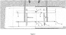
- the first connector 12 and second connector 13 are shown from above.
- the relative lengths and widths of the third, fourth, seventh and eighth elongate conductors 32, 34, 36, 38, and the first and second insulators 40, 42 are clearly visible.
- the eighth elongate conductor 38 has both ends inward of the ends of the seventh elongate conductor 36, as shown by lines AA and BB.
- the second insulator 42 is longer than the first insulator 40.
- the pivoting arms 28, 30 of the first connector 12 are shown in a partially extended position.
- the biasing arrangement of the second charging conductor 13 is also illustrated in this Figure.
- the fourth and eighth elongate conductors 34, 38 are mounted to the charging gantry 210 via springs, and are suspended on the springs a few centimetres below the level of the third and seventh elongate conductors 32, 36.
- the second and sixth elongate conductors 18, 22 will push upwardly on the fourth and eighth elongate conductors 34, 38.
- the fourth and eighth elongate conductors 34, 38 will move against the springs 44.
- the vertical offset between the third and seventh elongate conductors 32, 36 and the fourth and eighth elongate conductors 34, 38 is automatically adjusted when the vehicle is engaged in the charging station. If the vehicle is parked on a flat surface and the conductors are undamaged then the fourth and eighth elongate conductors 34, 38 will be lifted to the same height as the third and seventh elongate conductors 32, 36 when charging is in progress.
- the force required to move the fourth and eighth elongate conductors 34, 38 against the springs 44 is around 10 to 15 Newtons.
- the pivoting arms 28, 30 may push the second and sixth elongate conductors 18, (22) with a force of around 80 Newtons. Therefore, when charging, the first and second connectors 12, 13 will push against each other with a force of around 65 Newtons, which is sufficient to provide a good electrical connection.
- the arrangement of the first and second elongate conductors 16, 18 is best seen in Figure 4 .
- the first and second elongate conductors 16, 18 extend from either side of a central insulating mount 24.
- the overall extent of the first and second conductors 16, 18 from the mount 24 is similar.
- the area of the actual electrical contact 46 which can form an electrical connection with the second charging connector 13 is substantially reduced on the second elongate conductor 18 relative to the first elongate conductor 16.
- the electrical contact of the first elongate conductor extends across substantially the entire length of the conductor 16.
- the electrical contact 46 of the second elongate conductor 18 has an overall shorter length than the electrical contact of the first elongate conductor 16.
- the electrical contact 46 of the second elongate conductor 18, together with the spacing between the third and fourth conductors (32, 34) defines a working area 48 on the first elongate conductor 16.
- the working area 48 is inward of the ends of the first elongate conductor 16, ensuring a good stable connection to the first elongate conductor 16.
- the arrangement of electrical contacts can be embodied in a number of different ways.
- the electrical contact 46 of the second elongate conductor 18 may be formed as a raised area on a surface of the conductor, or as a conducting section surrounded by insulating material.
- the central mount 24 may be extended and the second elongate conductor 18 shortened, with the electrical contact 46 extending along the entire length of the second elongate conductor 18.
Landscapes
- Engineering & Computer Science (AREA)
- Mechanical Engineering (AREA)
- Power Engineering (AREA)
- Transportation (AREA)
- Charge And Discharge Circuits For Batteries Or The Like (AREA)
- Electric Propulsion And Braking For Vehicles (AREA)
Claims (15)
- Fahrzeugladeanordnung (10), die einen ersten und zweiten Verbinder (12, 13) umfasst, wobei ein Verbinder (12) an ein Fahrzeug (200) montierbar ist und der andere Verbinder (13) an ein Ladeportal (210) montierbar ist,der erste Verbinder (12) einen ersten und zweiten länglichen Leiter (16, 18) umfasst, wobei der erste und zweite längliche Leiter (16, 18) jeweils über einen länglichen elektrischen Kontakt zur Bildung einer elektrischen Verbindung mit dem zweiten Ladeverbinder (13) verfügen, wobei jeder elektrische Kontakt über ein proximales Ende nahe am anderen Leiter und ein distales Ende weiter entfernt vom anderen Leiter verfügt, der erste und zweite längliche Leiter (16, 18) in Längsrichtung im Abstand angeordnet und parallel oder linear zueinander angeordnet sind, der erste Verbinder (12) mit dem ersten und zweiten länglichen Leiter (16, 18) im Verhältnis zum Fahrzeug (200) zur Verbindung mit dem zweiten Verbinder (13) beweglich ist,der elektrische Kontakt des zweiten länglichen Leiters (18) über eine Längserstreckung verfügt, die kürzer als die Längserstreckung des elektrischen Kontakts des ersten länglichen Leiters (16) ist, undder zweite Verbinder (13) einen dritten und vierten länglichen Leiter (32, 34) umfasst, wobei der dritte und vierte längliche Leiter (32, 34) jeweils über einen länglichen elektrischen Kontakt zur Bildung einer elektrischen Verbindung mit dem ersten Ladeverbinder (12) verfügen, der dritte und vierte längliche Leiter (32, 34) über parallel zueinander verlaufende Längsachsen verfügen und der dritte und vierte längliche Leiter (32, 34) in senkrechter Richtung zu ihren Längsachsen im Abstand voneinander angeordnet sind,wobei der Abstand zwischen den elektrischen Kontakten des dritten und vierten länglichen Leiters (32, 34) größer als die Entfernung zwischen dem distalen Ende des elektrischen Kontakts des zweiten länglichen Leiters (18) und dem proximalen Ende des elektrischen Kontakts des ersten länglichen Leiters (16) und kürzer als die Entfernung zwischen dem proximalen Ende des elektrischen Kontakts des zweiten länglichen Leiters (18) und dem distalen Ende des elektrischen Kontakts des ersten länglichen Leiters (16) ist,wobei der erste längliche Leiter (16) angepasst ist, um eine Hochleistungsverbindung mit dem dritten länglichen Leiter (32) bereitzustellen, und der zweite längliche Leiter (18) angepasst ist, um eine Hochleistungsverbindung mit dem vierten länglichen Leiter (34) bereitzustellen.
- Fahrzeugladeanordnung nach Anspruch 1, in der der erste Verbinder (12) an ein Fahrzeug (200) montierbar ist und der zweite Verbinder (13) an ein Ladeportal (210) montierbar ist.
- Fahrzeugladeanordnung (10) nach Anspruch 2, in der der erste Verbinder (12) an ein Fahrzeug (200) montiert ist, wobei der erste und zweite längliche Leiter (16, 18) wesentlich senkrecht zu einer Längsachse des Fahrzeugs (200) verlaufen.
- Fahrzeugladeanordnung nach Anspruch 1, in der der erste Verbinder (12) an ein Ladeportal (210) montierbar ist und der zweite Verbinder (13) an ein Fahrzeug (200) montierbar ist.
- Fahrzeugladeanordnung (10) nach einem der vorstehenden Ansprüche, in der das Ladeportal (210) ein obenliegendes Ladeportal ist und einer der Verbinder (12) an ein Fahrzeugdach montierbar ist.
- Fahrzeugladeanordnung (10) nach einem der vorstehenden Ansprüche, in der der erste und zweite längliche Leiter (16, 18) auf der gleichen Linie wie der jeweils andere Leiter angeordnet sind.
- Fahrzeugladeanordnung (10) nach einem der vorstehenden Ansprüche, in der zwischen dem ersten und zweiten länglichen Leiter (16, 18) ein Isolator oder ein Luftspalt bereitgestellt ist.
- Fahrzeugladeanordnung (10) nach einem der vorstehenden Ansprüche, in der einer des ersten und zweiten Verbinders (12) beweglich montierbar an ein Fahrzeug (200) ist.
- Fahrzeugladeanordnung nach einem der vorstehenden Ansprüche, in der einer des ersten und zweiten Verbinders (12, 13) beweglich montierbar an ein Ladeportal (210) ist.
- Fahrzeugladeanordnung (10) nach Anspruch 8 oder Anspruch 9, in der mindestens ein beweglich montierbarer Verbinder (12) auf einem Schwenkarm zwischen einer eingefahrenen Position und einer ausgefahrenen Position beweglich ist.
- Fahrzeugladeanordnung (10) nach Anspruch 10, in der der beweglich montierbare Verbinder (12) in der ausgefahrenen Position in Richtung der ausgefahrenen Position gespannt, jedoch in Richtung der eingefahrenen Position bei Anwendung von Kraft auf den Verbinder beweglich ist.
- Fahrzeugladeanordnung (10) nach einem der vorstehenden Ansprüche, in der der elektrische Kontakt des zweiten länglichen Leiters (18) vom elektrischen Kontakt des ersten länglichen Leiters (16) vertikal versetzt ist.
- Fahrzeugladeanordnung (10) nach einem der vorstehenden Ansprüche, in der der vierte längliche Leiter (34) in Richtung einer Ruheposition gespannt und aus der Ruheposition in senkrechter Richtung zur Längsachse des vierten länglichen Leiters (34) und ebenfalls senkrecht zum Abstand zwischen dem dritten und vierten länglichen Leiter (32, 34) beweglich ist, wenn Kraft auf den vierten länglichen Leiter (34) angewandt wird.
- Fahrzeugladeanordnung (10) nach einem der vorstehenden Ansprüche, in der der elektrische Kontakt des vierten länglichen Leiters (34) kürzer als der elektrische Kontakt des dritten länglichen Leiters (32) ist und in der die elektrischen Kontakte der dritten und vierten länglichen Leiter (32, 34) nebeneinander angeordnet sind, wobei sich beide Enden des elektrischen Kontakts des vierten länglichen Leiters (34) innerhalb der Enden des elektrischen Kontakts des dritten länglichen Leiters (32) befinden.
- Fahrzeugladeanordnung nach einem der vorstehenden Ansprüche, in der der vierte längliche Leiter (34) senkrecht zu seiner Längsachse und parallel zu den Abständen zwischen dem dritten und vierten länglichen Leiter (32, 34) über eine Breite verfügt, die kleiner als die entsprechende Breite des dritten länglichen Leiters (32) ist.
Priority Applications (2)
| Application Number | Priority Date | Filing Date | Title |
|---|---|---|---|
| EP16184146.5A EP3115248B1 (de) | 2013-06-25 | 2014-06-24 | Fahrzeugladeverbinder |
| DK16184146T DK3115248T3 (da) | 2013-06-25 | 2014-06-24 | Køretøjsladestik |
Applications Claiming Priority (2)
| Application Number | Priority Date | Filing Date | Title |
|---|---|---|---|
| GBGB1311246.1A GB201311246D0 (en) | 2013-06-25 | 2013-06-25 | Vehicle charging connectors |
| PCT/IB2014/001166 WO2014207537A2 (en) | 2013-06-25 | 2014-06-24 | Vehicle charging connectors |
Related Child Applications (2)
| Application Number | Title | Priority Date | Filing Date |
|---|---|---|---|
| EP16184146.5A Division-Into EP3115248B1 (de) | 2013-06-25 | 2014-06-24 | Fahrzeugladeverbinder |
| EP16184146.5A Division EP3115248B1 (de) | 2013-06-25 | 2014-06-24 | Fahrzeugladeverbinder |
Publications (2)
| Publication Number | Publication Date |
|---|---|
| EP3013623A2 EP3013623A2 (de) | 2016-05-04 |
| EP3013623B1 true EP3013623B1 (de) | 2018-06-06 |
Family
ID=48998888
Family Applications (2)
| Application Number | Title | Priority Date | Filing Date |
|---|---|---|---|
| EP14745231.2A Active EP3013623B1 (de) | 2013-06-25 | 2014-06-24 | Ladeverbinder für ein fahrzeug |
| EP16184146.5A Active EP3115248B1 (de) | 2013-06-25 | 2014-06-24 | Fahrzeugladeverbinder |
Family Applications After (1)
| Application Number | Title | Priority Date | Filing Date |
|---|---|---|---|
| EP16184146.5A Active EP3115248B1 (de) | 2013-06-25 | 2014-06-24 | Fahrzeugladeverbinder |
Country Status (8)
| Country | Link |
|---|---|
| US (1) | US20160167524A1 (de) |
| EP (2) | EP3013623B1 (de) |
| CN (2) | CN105392658B (de) |
| AU (2) | AU2014300694B2 (de) |
| DK (2) | DK3013623T3 (de) |
| ES (2) | ES2684313T3 (de) |
| GB (1) | GB201311246D0 (de) |
| WO (1) | WO2014207537A2 (de) |
Families Citing this family (13)
| Publication number | Priority date | Publication date | Assignee | Title |
|---|---|---|---|---|
| GB2526118A (en) * | 2014-05-14 | 2015-11-18 | Sylvan Ascent Inc | Vehicle charging arrangement |
| CN104149632B (zh) * | 2014-08-19 | 2016-03-16 | 安徽理工大学 | 三自由度混联减振受电弓 |
| DE102016205012A1 (de) * | 2016-03-24 | 2017-09-28 | Schunk Bahn- Und Industrietechnik Gmbh | Positioniereinheit und Verfahren zur Kontaktierung |
| DE102017000916A1 (de) * | 2017-02-02 | 2018-08-02 | Man Truck & Bus Ag | Vorrichtung zum Aufladen eines elektrischen Energiespeichers eines einen elektrischen Antrieb aufweisenden Fahrzeugs |
| DE102017000915A1 (de) * | 2017-02-02 | 2018-08-02 | Man Truck & Bus Ag | Vorrichtung zum Aufladen eines elektrischen Energiespeichers eines einen elektrischen Antrieb aufweisenden Fahrzeugs |
| DE102017000917A1 (de) * | 2017-02-02 | 2018-08-02 | Man Truck & Bus Ag | Vorrichtung zum Aufladen eines elektrischen Energiespeichers eines einen elektrischen Antrieb aufweisenden Fahrzeugs |
| DE102018106046B3 (de) | 2018-03-15 | 2019-03-14 | Schunk Bahn- Und Industrietechnik Gmbh | Schnellladesystem und Verfahren zur elektrischen Verbindung eines Fahrzeugs mit einer Ladestation |
| CN108775860B (zh) * | 2018-05-10 | 2024-11-19 | 深圳精智机器有限公司 | 一种充电检测机构 |
| US10906413B2 (en) * | 2018-11-30 | 2021-02-02 | Proterra Inc. | Charging system including operatively independent chargers for an electric vehicle |
| FR3105116B1 (fr) * | 2019-12-23 | 2023-01-06 | Alstom Transp Tech | Dispositif de captage d’énergie électrique pour véhicule, notamment ferroviaire, et véhicule, notamment ferroviaire, comprenant un tel dispositif |
| SE544156C2 (en) * | 2020-06-09 | 2022-02-08 | Scania Cv Ab | An apparatus for the electrical charging of an electrical battery unit of a vehicle |
| EP4209382A1 (de) * | 2022-01-11 | 2023-07-12 | ABB E-Mobility B.V. | Isolationsbarrierenschutz an mehrpoligen stromabnehmern |
| US12570168B2 (en) * | 2022-03-07 | 2026-03-10 | Transportation Ip Holdings, Llc | Vehicle power supply system |
Family Cites Families (9)
| Publication number | Priority date | Publication date | Assignee | Title |
|---|---|---|---|---|
| US3955657A (en) * | 1974-02-15 | 1976-05-11 | Oscar Bossi | Electric traction transportation system with storage battery powered vehicles and fast recharge at the vehicle stops |
| GB1480311A (en) * | 1975-01-08 | 1977-07-20 | London Transport Executive | Current collection from overhead wires for vehicles |
| BG103377A (en) * | 1999-04-30 | 2001-04-30 | Христо РИБАРЕВ | Device for energy accumulation and recuperation in electrically driven motor transport vehicles |
| FR2916696B1 (fr) * | 2007-05-31 | 2010-08-27 | Iveco France | Systeme de transport en commun, vehicule electrique et station de regeneration pour ce systeme |
| CN101353018B (zh) * | 2007-07-24 | 2010-08-25 | 巫宗进 | 在行驶中能充电的电动汽车 |
| EP2296933B1 (de) * | 2008-07-01 | 2016-10-05 | Proterra Inc. | Aufladestationen für elektrofahrzeuge |
| FR2940201B1 (fr) * | 2008-12-22 | 2014-04-11 | Delachaux Sa | Systemes et ensemble de connexion pour la charge d'un vehicule electrique |
| GB2475703A (en) * | 2009-11-26 | 2011-06-01 | Sylvan Ascent Inc | Electric vehicle charging station and charge receiving arrangement for a vehicle |
| CN102917907A (zh) * | 2009-12-23 | 2013-02-06 | 普罗特拉公司 | 用于电动车辆的充电站 |
-
2013
- 2013-06-25 GB GBGB1311246.1A patent/GB201311246D0/en not_active Ceased
-
2014
- 2014-06-24 AU AU2014300694A patent/AU2014300694B2/en active Active
- 2014-06-24 US US14/908,694 patent/US20160167524A1/en not_active Abandoned
- 2014-06-24 ES ES14745231.2T patent/ES2684313T3/es active Active
- 2014-06-24 ES ES16184146T patent/ES2749898T3/es active Active
- 2014-06-24 WO PCT/IB2014/001166 patent/WO2014207537A2/en not_active Ceased
- 2014-06-24 EP EP14745231.2A patent/EP3013623B1/de active Active
- 2014-06-24 DK DK14745231.2T patent/DK3013623T3/en active
- 2014-06-24 CN CN201480036337.6A patent/CN105392658B/zh active Active
- 2014-06-24 EP EP16184146.5A patent/EP3115248B1/de active Active
- 2014-06-24 CN CN201710452633.XA patent/CN107298023B/zh active Active
- 2014-06-24 DK DK16184146T patent/DK3115248T3/da active
-
2017
- 2017-12-01 AU AU2017268663A patent/AU2017268663B2/en active Active
Non-Patent Citations (1)
| Title |
|---|
| None * |
Also Published As
| Publication number | Publication date |
|---|---|
| ES2749898T3 (es) | 2020-03-24 |
| AU2017268663B2 (en) | 2019-01-31 |
| EP3115248A1 (de) | 2017-01-11 |
| DK3115248T3 (da) | 2019-11-18 |
| AU2014300694A1 (en) | 2016-02-18 |
| CN105392658B (zh) | 2018-04-13 |
| GB201311246D0 (en) | 2013-08-14 |
| ES2684313T3 (es) | 2018-10-02 |
| WO2014207537A3 (en) | 2015-07-23 |
| US20160167524A1 (en) | 2016-06-16 |
| WO2014207537A2 (en) | 2014-12-31 |
| CN107298023B (zh) | 2020-08-25 |
| CN107298023A (zh) | 2017-10-27 |
| EP3013623A2 (de) | 2016-05-04 |
| EP3115248B1 (de) | 2019-08-21 |
| AU2017268663A1 (en) | 2017-12-21 |
| DK3013623T3 (en) | 2018-08-13 |
| AU2014300694B2 (en) | 2018-05-10 |
| CN105392658A (zh) | 2016-03-09 |
Similar Documents
| Publication | Publication Date | Title |
|---|---|---|
| EP3013623B1 (de) | Ladeverbinder für ein fahrzeug | |
| US11453299B2 (en) | Electric vehicles and charging stations | |
| US9446672B2 (en) | Charging systems for electric vehicles | |
| EP2819876B1 (de) | Stromübertragungsvorrichtung zur aufladung elektrischer energiespeicher von fahrzeugen an überkopfladestationen | |
| EP2848451B1 (de) | Verbindungssystem zum Laden von Batterien eines Fahrzeugs, insbesondere eines elektrischen Busses | |
| CN105339203A (zh) | 用于电动车辆的保护设备 | |
| CN209063907U (zh) | 弓头单元以及充电弓 | |
| WO2014207540A2 (en) | Overhead changing arrangement for a vehicle | |
| CN208069426U (zh) | 道路式移动充电系统 | |
| CN209780382U (zh) | 车库充电结构及其智能车库 | |
| CN212579622U (zh) | 用于车辆的取流装置和车辆 | |
| CN211869170U (zh) | 用于电动汽车的电弓装置、充电桩和电动汽车 | |
| EP4159521A1 (de) | Kontaktkopf für elektrische fahrzeuge, schnellladesystem und verfahren zur herstellung einer elektrisch leitenden verbindung zwischen der ladestation und dem kontaktkopf | |
| CN112297855B (zh) | 有轨电车和具有其的轨道交通系统 | |
| WO2016046028A1 (en) | Vehicle charger |
Legal Events
| Date | Code | Title | Description |
|---|---|---|---|
| PUAI | Public reference made under article 153(3) epc to a published international application that has entered the european phase |
Free format text: ORIGINAL CODE: 0009012 |
|
| 17P | Request for examination filed |
Effective date: 20160106 |
|
| AK | Designated contracting states |
Kind code of ref document: A2 Designated state(s): AL AT BE BG CH CY CZ DE DK EE ES FI FR GB GR HR HU IE IS IT LI LT LU LV MC MK MT NL NO PL PT RO RS SE SI SK SM TR |
|
| AX | Request for extension of the european patent |
Extension state: BA ME |
|
| DAX | Request for extension of the european patent (deleted) | ||
| GRAP | Despatch of communication of intention to grant a patent |
Free format text: ORIGINAL CODE: EPIDOSNIGR1 |
|
| INTG | Intention to grant announced |
Effective date: 20180316 |
|
| GRAS | Grant fee paid |
Free format text: ORIGINAL CODE: EPIDOSNIGR3 |
|
| GRAA | (expected) grant |
Free format text: ORIGINAL CODE: 0009210 |
|
| RAP1 | Party data changed (applicant data changed or rights of an application transferred) |
Owner name: FURRER + FREY AG |
|
| AK | Designated contracting states |
Kind code of ref document: B1 Designated state(s): AL AT BE BG CH CY CZ DE DK EE ES FI FR GB GR HR HU IE IS IT LI LT LU LV MC MK MT NL NO PL PT RO RS SE SI SK SM TR |
|
| REG | Reference to a national code |
Ref country code: GB Ref legal event code: FG4D |
|
| REG | Reference to a national code |
Ref country code: CH Ref legal event code: EP Ref country code: AT Ref legal event code: REF Ref document number: 1005700 Country of ref document: AT Kind code of ref document: T Effective date: 20180615 |
|
| REG | Reference to a national code |
Ref country code: IE Ref legal event code: FG4D |
|
| REG | Reference to a national code |
Ref country code: DE Ref legal event code: R096 Ref document number: 602014026660 Country of ref document: DE |
|
| REG | Reference to a national code |
Ref country code: FR Ref legal event code: PLFP Year of fee payment: 5 |
|
| REG | Reference to a national code |
Ref country code: DK Ref legal event code: T3 Effective date: 20180808 |
|
| REG | Reference to a national code |
Ref country code: CH Ref legal event code: NV Representative=s name: EUROMAIER AG, CH Ref country code: NL Ref legal event code: FP |
|
| REG | Reference to a national code |
Ref country code: NO Ref legal event code: T2 Effective date: 20180606 |
|
| REG | Reference to a national code |
Ref country code: SE Ref legal event code: TRGR |
|
| REG | Reference to a national code |
Ref country code: ES Ref legal event code: FG2A Ref document number: 2684313 Country of ref document: ES Kind code of ref document: T3 Effective date: 20181002 |
|
| REG | Reference to a national code |
Ref country code: LT Ref legal event code: MG4D |
|
| PG25 | Lapsed in a contracting state [announced via postgrant information from national office to epo] |
Ref country code: BG Free format text: LAPSE BECAUSE OF FAILURE TO SUBMIT A TRANSLATION OF THE DESCRIPTION OR TO PAY THE FEE WITHIN THE PRESCRIBED TIME-LIMIT Effective date: 20180906 Ref country code: FI Free format text: LAPSE BECAUSE OF FAILURE TO SUBMIT A TRANSLATION OF THE DESCRIPTION OR TO PAY THE FEE WITHIN THE PRESCRIBED TIME-LIMIT Effective date: 20180606 Ref country code: CY Free format text: LAPSE BECAUSE OF FAILURE TO SUBMIT A TRANSLATION OF THE DESCRIPTION OR TO PAY THE FEE WITHIN THE PRESCRIBED TIME-LIMIT Effective date: 20180606 Ref country code: LT Free format text: LAPSE BECAUSE OF FAILURE TO SUBMIT A TRANSLATION OF THE DESCRIPTION OR TO PAY THE FEE WITHIN THE PRESCRIBED TIME-LIMIT Effective date: 20180606 |
|
| PG25 | Lapsed in a contracting state [announced via postgrant information from national office to epo] |
Ref country code: LV Free format text: LAPSE BECAUSE OF FAILURE TO SUBMIT A TRANSLATION OF THE DESCRIPTION OR TO PAY THE FEE WITHIN THE PRESCRIBED TIME-LIMIT Effective date: 20180606 Ref country code: RS Free format text: LAPSE BECAUSE OF FAILURE TO SUBMIT A TRANSLATION OF THE DESCRIPTION OR TO PAY THE FEE WITHIN THE PRESCRIBED TIME-LIMIT Effective date: 20180606 Ref country code: HR Free format text: LAPSE BECAUSE OF FAILURE TO SUBMIT A TRANSLATION OF THE DESCRIPTION OR TO PAY THE FEE WITHIN THE PRESCRIBED TIME-LIMIT Effective date: 20180606 Ref country code: GR Free format text: LAPSE BECAUSE OF FAILURE TO SUBMIT A TRANSLATION OF THE DESCRIPTION OR TO PAY THE FEE WITHIN THE PRESCRIBED TIME-LIMIT Effective date: 20180907 |
|
| PG25 | Lapsed in a contracting state [announced via postgrant information from national office to epo] |
Ref country code: EE Free format text: LAPSE BECAUSE OF FAILURE TO SUBMIT A TRANSLATION OF THE DESCRIPTION OR TO PAY THE FEE WITHIN THE PRESCRIBED TIME-LIMIT Effective date: 20180606 Ref country code: IS Free format text: LAPSE BECAUSE OF FAILURE TO SUBMIT A TRANSLATION OF THE DESCRIPTION OR TO PAY THE FEE WITHIN THE PRESCRIBED TIME-LIMIT Effective date: 20181006 Ref country code: PL Free format text: LAPSE BECAUSE OF FAILURE TO SUBMIT A TRANSLATION OF THE DESCRIPTION OR TO PAY THE FEE WITHIN THE PRESCRIBED TIME-LIMIT Effective date: 20180606 Ref country code: RO Free format text: LAPSE BECAUSE OF FAILURE TO SUBMIT A TRANSLATION OF THE DESCRIPTION OR TO PAY THE FEE WITHIN THE PRESCRIBED TIME-LIMIT Effective date: 20180606 Ref country code: CZ Free format text: LAPSE BECAUSE OF FAILURE TO SUBMIT A TRANSLATION OF THE DESCRIPTION OR TO PAY THE FEE WITHIN THE PRESCRIBED TIME-LIMIT Effective date: 20180606 Ref country code: SK Free format text: LAPSE BECAUSE OF FAILURE TO SUBMIT A TRANSLATION OF THE DESCRIPTION OR TO PAY THE FEE WITHIN THE PRESCRIBED TIME-LIMIT Effective date: 20180606 |
|
| PG25 | Lapsed in a contracting state [announced via postgrant information from national office to epo] |
Ref country code: SM Free format text: LAPSE BECAUSE OF FAILURE TO SUBMIT A TRANSLATION OF THE DESCRIPTION OR TO PAY THE FEE WITHIN THE PRESCRIBED TIME-LIMIT Effective date: 20180606 |
|
| REG | Reference to a national code |
Ref country code: DE Ref legal event code: R097 Ref document number: 602014026660 Country of ref document: DE |
|
| REG | Reference to a national code |
Ref country code: IE Ref legal event code: MM4A |
|
| PG25 | Lapsed in a contracting state [announced via postgrant information from national office to epo] |
Ref country code: MC Free format text: LAPSE BECAUSE OF FAILURE TO SUBMIT A TRANSLATION OF THE DESCRIPTION OR TO PAY THE FEE WITHIN THE PRESCRIBED TIME-LIMIT Effective date: 20180606 |
|
| PLBE | No opposition filed within time limit |
Free format text: ORIGINAL CODE: 0009261 |
|
| STAA | Information on the status of an ep patent application or granted ep patent |
Free format text: STATUS: NO OPPOSITION FILED WITHIN TIME LIMIT |
|
| PG25 | Lapsed in a contracting state [announced via postgrant information from national office to epo] |
Ref country code: IE Free format text: LAPSE BECAUSE OF NON-PAYMENT OF DUE FEES Effective date: 20180624 |
|
| 26N | No opposition filed |
Effective date: 20190307 |
|
| PG25 | Lapsed in a contracting state [announced via postgrant information from national office to epo] |
Ref country code: SI Free format text: LAPSE BECAUSE OF FAILURE TO SUBMIT A TRANSLATION OF THE DESCRIPTION OR TO PAY THE FEE WITHIN THE PRESCRIBED TIME-LIMIT Effective date: 20180606 |
|
| PG25 | Lapsed in a contracting state [announced via postgrant information from national office to epo] |
Ref country code: AL Free format text: LAPSE BECAUSE OF FAILURE TO SUBMIT A TRANSLATION OF THE DESCRIPTION OR TO PAY THE FEE WITHIN THE PRESCRIBED TIME-LIMIT Effective date: 20180606 |
|
| PG25 | Lapsed in a contracting state [announced via postgrant information from national office to epo] |
Ref country code: MT Free format text: LAPSE BECAUSE OF NON-PAYMENT OF DUE FEES Effective date: 20180624 |
|
| PG25 | Lapsed in a contracting state [announced via postgrant information from national office to epo] |
Ref country code: TR Free format text: LAPSE BECAUSE OF FAILURE TO SUBMIT A TRANSLATION OF THE DESCRIPTION OR TO PAY THE FEE WITHIN THE PRESCRIBED TIME-LIMIT Effective date: 20180606 |
|
| PG25 | Lapsed in a contracting state [announced via postgrant information from national office to epo] |
Ref country code: PT Free format text: LAPSE BECAUSE OF FAILURE TO SUBMIT A TRANSLATION OF THE DESCRIPTION OR TO PAY THE FEE WITHIN THE PRESCRIBED TIME-LIMIT Effective date: 20180606 |
|
| PG25 | Lapsed in a contracting state [announced via postgrant information from national office to epo] |
Ref country code: MK Free format text: LAPSE BECAUSE OF NON-PAYMENT OF DUE FEES Effective date: 20180606 Ref country code: HU Free format text: LAPSE BECAUSE OF FAILURE TO SUBMIT A TRANSLATION OF THE DESCRIPTION OR TO PAY THE FEE WITHIN THE PRESCRIBED TIME-LIMIT; INVALID AB INITIO Effective date: 20140624 |
|
| REG | Reference to a national code |
Ref country code: CH Ref legal event code: PCAR Free format text: NEW ADDRESS: BERGLIHOEH 3, 8725 ERNETSCHWIL (CH) |
|
| REG | Reference to a national code |
Ref country code: AT Ref legal event code: UEP Ref document number: 1005700 Country of ref document: AT Kind code of ref document: T Effective date: 20180606 |
|
| REG | Reference to a national code |
Ref country code: DE Ref legal event code: R082 Ref document number: 602014026660 Country of ref document: DE Representative=s name: VON BUELOW & TAMADA PATENTANWALTSGESELLSCHAFT, DE |
|
| PGFP | Annual fee paid to national office [announced via postgrant information from national office to epo] |
Ref country code: DE Payment date: 20250613 Year of fee payment: 12 |
|
| PGFP | Annual fee paid to national office [announced via postgrant information from national office to epo] |
Ref country code: DK Payment date: 20250624 Year of fee payment: 12 Ref country code: GB Payment date: 20250527 Year of fee payment: 12 |
|
| PGFP | Annual fee paid to national office [announced via postgrant information from national office to epo] |
Ref country code: NO Payment date: 20250624 Year of fee payment: 12 |
|
| PGFP | Annual fee paid to national office [announced via postgrant information from national office to epo] |
Ref country code: LU Payment date: 20250613 Year of fee payment: 12 Ref country code: NL Payment date: 20250613 Year of fee payment: 12 Ref country code: BE Payment date: 20250613 Year of fee payment: 12 |
|
| PGFP | Annual fee paid to national office [announced via postgrant information from national office to epo] |
Ref country code: FR Payment date: 20250616 Year of fee payment: 12 |
|
| PGFP | Annual fee paid to national office [announced via postgrant information from national office to epo] |
Ref country code: AT Payment date: 20250613 Year of fee payment: 12 |
|
| PGFP | Annual fee paid to national office [announced via postgrant information from national office to epo] |
Ref country code: SE Payment date: 20250626 Year of fee payment: 12 |
|
| PGFP | Annual fee paid to national office [announced via postgrant information from national office to epo] |
Ref country code: ES Payment date: 20250702 Year of fee payment: 12 |
|
| PGFP | Annual fee paid to national office [announced via postgrant information from national office to epo] |
Ref country code: IT Payment date: 20250630 Year of fee payment: 12 |
|
| PGFP | Annual fee paid to national office [announced via postgrant information from national office to epo] |
Ref country code: CH Payment date: 20250701 Year of fee payment: 12 |