EP3013633B1 - Console destinée à un siège de véhicule, procédé de fabrication d'une console et siège de véhicule - Google Patents
Console destinée à un siège de véhicule, procédé de fabrication d'une console et siège de véhicule Download PDFInfo
- Publication number
- EP3013633B1 EP3013633B1 EP14733627.5A EP14733627A EP3013633B1 EP 3013633 B1 EP3013633 B1 EP 3013633B1 EP 14733627 A EP14733627 A EP 14733627A EP 3013633 B1 EP3013633 B1 EP 3013633B1
- Authority
- EP
- European Patent Office
- Prior art keywords
- console
- vehicle seat
- console body
- panel
- vehicle
- Prior art date
- Legal status (The legal status is an assumption and is not a legal conclusion. Google has not performed a legal analysis and makes no representation as to the accuracy of the status listed.)
- Active
Links
Images


Classifications
-
- B—PERFORMING OPERATIONS; TRANSPORTING
- B60—VEHICLES IN GENERAL
- B60N—SEATS SPECIALLY ADAPTED FOR VEHICLES; VEHICLE PASSENGER ACCOMMODATION NOT OTHERWISE PROVIDED FOR
- B60N2/00—Seats specially adapted for vehicles; Arrangement or mounting of seats in vehicles
- B60N2/005—Arrangement or mounting of seats in vehicles, e.g. dismountable auxiliary seats
- B60N2/015—Attaching seats directly to vehicle chassis
-
- B—PERFORMING OPERATIONS; TRANSPORTING
- B60—VEHICLES IN GENERAL
- B60N—SEATS SPECIALLY ADAPTED FOR VEHICLES; VEHICLE PASSENGER ACCOMMODATION NOT OTHERWISE PROVIDED FOR
- B60N2/00—Seats specially adapted for vehicles; Arrangement or mounting of seats in vehicles
- B60N2/005—Arrangement or mounting of seats in vehicles, e.g. dismountable auxiliary seats
-
- B—PERFORMING OPERATIONS; TRANSPORTING
- B62—LAND VEHICLES FOR TRAVELLING OTHERWISE THAN ON RAILS
- B62D—MOTOR VEHICLES; TRAILERS
- B62D65/00—Designing, manufacturing, e.g. assembling, facilitating disassembly, or structurally modifying motor vehicles or trailers, not otherwise provided for
- B62D65/02—Joining sub-units or components to, or positioning sub-units or components with respect to, body shell or other sub-units or components
- B62D65/14—Joining sub-units or components to, or positioning sub-units or components with respect to, body shell or other sub-units or components the sub-units or components being passenger compartment fittings, e.g. seats, linings, trim, instrument panels
Definitions
- the invention relates to a console for a vehicle seat, in particular for a utility vehicle seat, with the features of the preamble of claim 1, and a method for producing such a console with the features of claim 8.
- the invention also relates to a vehicle seat, in particular a utility vehicle seat, with the features of claim 13.
- a special console is used in each case, which is connected, in particular screwed or riveted, to the floor of the vehicle and to the utility vehicle seat.
- a preset of the seat height that is, the distance of the seat, or a subframe of the vehicle seat, from the vehicle floor by the console.
- a holder with a rotating shield wherein a vehicle seat is connected via a height adjustment with the holder.
- a likewise connected to the holder and the height adjustment enclosing shield is located, in particular not in the power flow between the vehicle seat and the bracket or a vehicle structure connected to the bracket.
- a fastening plate for a vehicle seat is known, which is permanently connectable to a vehicle structure and provides bolts to which a vehicle seat can be releasably secured by means of rotary latch locks provided for this purpose.
- the invention is based on the object to provide a console of the type mentioned, which is adaptable to several, different vehicle types.
- a generic console for a vehicle seat comprises a console body, which is connectable to the vehicle seat.
- the console comprises at least one base plate connected to the console body, which is connectable to a vehicle floor.
- the console itself is adapted to the vehicle seat and independent of the vehicle.
- the console body is bolted to the bottom plate.
- Other attachment options such as welding, are conceivable.
- the bottom plate on holes whose positions are adapted to hole patterns of different vehicle floors.
- the console is thus modular. It can be various console bodies, which differ, for example, in their extent in the vertical direction, are connected to the same bottom plate to a console.
- the console body preferably has a cuboid shape.
- the console body is made of a board, which represents a settlement of the console body.
- the board has a base, two top surfaces, two stiffening surfaces, a front surface, a rear surface, two side surfaces and a plurality of tabs for welding to the front surface and the rear surface.
- the stiffening surfaces after preparation of the console body are angled relative to the top surfaces by about 45 ° and protrude into the interior of the console body.
- the strength of the console body is advantageously increased.
- a console body which is connectable to a vehicle seat, connected to a bottom plate which is connectable to a vehicle floor.
- the console body is screwed to a bottom plate.
- Other attachment options such as welding, are conceivable.
- the console body is made of a board, which represents a development of the console body.
- the board is cut out of a base plate, and the board is folded at predetermined lines and then welded so that the console body is formed.
- the board has advantageous tabs.
- the board is preferably cut out by laser cutting, whereby the desired shape can be precisely met.
- the vehicle seat comprises a scissor frame, by means of which the height of a seat part of the vehicle seat is adjustable over the console.
- the vehicle seat comprises a rotating device, by means of which a seat part of the vehicle seat is rotatable relative to the console.
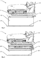
- a vehicle seat 1 for a commercial vehicle has a scissors-type frame 3 for height adjustment, which comprises a subframe 5, an upper frame 7 arranged above it, and a pair of crossed rockers 8a and 8b on both sides.
- a cross tube 10 connects the two crossing points and at the same time defines the scissors axis about which the rockers 8a and 8b can pivot relative to each other.
- the arrangement of the vehicle seat 1 within a commercial vehicle cabin and the usual direction of travel of the commercial vehicle define the directional information used below.
- a direction oriented perpendicular to the floor of the utility vehicle cabin is referred to below as a vertical direction and a direction perpendicular to the vertical direction and perpendicular to the direction of travel is referred to below as the transverse direction.
- the rockers 8a and 8b are hinged at their rear end to the subframe 5 and the upper frame 7 and each have at their front end rotatable rollers, by means of which they are movably guided in or on the upper frame 7 and subframe 5 in the seat longitudinal direction.
- the height of the upper frame 7 changes over the sub-frame 5, hereinafter referred to briefly as the height of the scissors-type frame 3.
- the scissor frame 3 is a vibratory system, which significantly increases the seating comfort.
- the two pairs of crossed rockers 8a and 8b each comprise a first rocker 8a, which is arranged externally, and a second rocker 8b, which is arranged inside.
- the two first rockers 8a are fixedly connected to each other at their one, in this case the front, lower end by means of a bearing tube 18, which at the same time supports the rollers.
- the two second rockers 8b are fixedly connected to each other by means of the cross tube 10. Further, the other ends of the corresponding rockers 8a or 8b are firmly connected to each other by means of further tubes.
- the vehicle seat 1 also has a seat frame 16, which is articulated on both sides on the one hand in its rear region on the upper frame 7 and on the other hand in its front region by means of a tilt adjuster can be raised and lowered and thus adjustable in its inclination relative to the scissor frame 3.
- the vehicle seat 1 still has a backrest 17, which is attached to the seat frame 16 in the present case adjustable in inclination.
- the backrest 17 can also be attached to the upper frame 7.
- the seat part 20 is, together with the scissor frame 3, displaceable by means of a pair of rails 15, whereby the vehicle seat 1 is translationally adjustable.
- the pair of rails 15 comprises two seat rails arranged parallel in a first plane, each of which has a bottom rail and a top rail movable relative thereto.
- the sub-frame 5 of the vehicle seat 1 is connected directly to the upper rails of the rail pair 15.
- the lower rails of the pair of rails 15 are connected to a bracket 101, in the present case screwed.
- the console 101 is in turn connected to the floor of the utility vehicle cabin, in this case bolted.
- the console 101 comprises a console body 103, which is connected to the lower rails of the rail pair 15, and a bottom plate 24 which is connected to the floor of the utility vehicle cabin.
- the console body 103 and the bottom plate 24 are also connected to each other, in this case screwed.
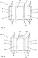
- a circuit board 105 is initially cut out of a base plate by means of laser cutting, which represents a development of the console body 103.
- the circuit board 105 comprises a base surface 60, two cover surfaces 70 and two stiffening surfaces 80.
- the circuit board 105 further comprises a front surface 110, a back surface 120 and two side surfaces 130 which abut against the base 60.
- the board 105 has tabs 50, which project laterally from the side surfaces 130, the top surfaces 70 and the stiffening surfaces 80.
- top surfaces 70 of the board 105 In the top surfaces 70 of the board 105 holes for mounting the lower rails of the rail pair 15 are introduced. In the base 60 of the board 105 holes for mounting the bottom plate 24 are introduced.
- the board 105 is folded at predetermined lines between the individual surfaces 60, 70, 80, 110, 120, 130 and between the surfaces 70, 80, 130 and the tabs 50, and the tabs 50 are connected to the front surface 110 and the rear surface 120 welded.
- the resulting console body 103 which has a cuboid shape, is then bolted to the bottom plate 24.
- the stiffening surfaces 80 of the console body 103 are angled relative to the top surfaces 70 by about 45 ° and protrude into the interior of the console body 103 inside.
- the vehicle seat 1 includes a rotating device 22.
- the rotating device 22 includes an upper plate to which the sub-frame 5 of the vehicle seat 1 is fixed, and a lower plate which is connected to the upper rails of the rail pair 15.
- the upper plate and the lower plate are rotatably supported relative to each other about a rotational axis extending in the vertical direction and can be fixed by means of a locking device in a set rotational position.
- the seat part 20 of the vehicle seat 1 is rotatable relative to the commercial vehicle cabin about the axis of rotation extending in the vertical direction.
- the lower rails of the pair of rails 15 are connected to a bracket 201, in this case screwed.
- the console 201 is in turn connected to the floor of the utility vehicle cabin, in this case screwed.
- the console 201 comprises a console body 203, which is connected to the lower rails of the rail pair 15, and a bottom plate 24 which is connected to the floor of the utility vehicle cabin.
- the bracket body 203 and the bottom plate 24 are also connected to each other, in this case screwed.
- a circuit board 205 is first cut out of a base plate by means of laser cutting, which represents a development of the console body 203.
- the circuit board 205 comprises a base surface 60, two cover surfaces 70 and two stiffening surfaces 80.
- the circuit board 205 further comprises a front surface 210, a rear surface 220 and two side surfaces 230, which bear against the base surface 60.
- the board 205 has tabs 50, which protrude laterally from the side surfaces 230, the top surfaces 70 and the stiffening surfaces 80.
- top surfaces 70 of the board 205 holes for mounting the lower rails of the rail pair 15 are introduced.
- base 60 of the board 205 holes for mounting the bottom plate 24 are introduced.
- the board 205 is folded at predetermined lines between the individual surfaces 60, 70, 80, 210, 220, 230 and between the surfaces 70, 80, 230 and the tabs 50, and the tabs 50 are connected to the front surface 210 and the rear surface 220 welded.
- the resulting console body 203 which has a cuboid shape, is then screwed to the bottom plate 24.
- the stiffening surfaces 80 of the console body 203 are angled relative to the top surfaces 70 by about 45 ° and protrude into the interior of the console body 203 inside.
- the console 101 and the console 201 differ in the present case only in their height, ie in their extension in the vertical direction.
- the console 101 and the console 201 each have a similar bottom plate 24, but different console body 103, 203.
- the console body 103 and the console body 203 differ in this case only in their height, ie in their extension in the vertical direction.
- the extension of the console body 203 in the vertical direction is less than the extension of the console body 103 in the vertical direction.
- the different extent of the console body 103, 203 in the vertical direction results from a different configuration of the mentioned boards 105, 205.
- the board 105 and the board 205 are designed similarly, however, the front surfaces 110, 210, the back surfaces 120, 220 and the side surfaces 130, 230, which extend in the vertical direction after the described folding, different.
- the front surface 110, the rear surface 120, and the side surfaces 130 extend farther away from the base 60 than the front surface 210, the back surface 220, and the side surfaces 230 on the circuit board 205 in the circuit board 105.
- the remaining surfaces 60, 70, 80 of the boards 105, 205 are similar.
- the holes in the top surfaces 70 for fixing the lower rails of the rail pair 15 and the holes in the base 60 for fixing the bottom plate 24 are introduced at the same locations.
- the bottom plate 24 comprises, on the one hand, bores for fastening a console body 103, 203.
- the same bores serve for fastening a console body 103 and for fastening a console body 203.
- the bottom plate 24 includes holes 28 for attachment to the floor of a utility vehicle cabin.
- the bottom plate 24 a plurality of holes and / or slots, which are adapted to hole patterns of various commercial vehicle cabins.
Landscapes
- Engineering & Computer Science (AREA)
- Transportation (AREA)
- Mechanical Engineering (AREA)
- Aviation & Aerospace Engineering (AREA)
- Manufacturing & Machinery (AREA)
- Chemical & Material Sciences (AREA)
- Combustion & Propulsion (AREA)
- Vehicle Step Arrangements And Article Storage (AREA)
- Seats For Vehicles (AREA)
Claims (15)
- Console (101, 201) pour un siège de véhicule (1), comprenant un corps de console (103, 203) et au moins une plaque d'embase (24) connectée à une surface de base (60) du corps de console (103, 203), laquelle peut être connectée à un plancher du véhicule, le corps de console (103, 203) présentant au moins une surface de recouvrement (70) espacée de la surface de base (60), laquelle peut être connectée au siège de véhicule (1).
- Console (101, 201) selon la revendication 1, caractérisée en ce que le corps de console (103, 203) est vissé à la plaque d'embase (24).
- Console (101, 201) selon l'une quelconque des revendications précédentes, caractérisée en ce que la plaque d'embase (24) présente des trous (28) dont les positions sont adaptées à des schémas de perçage de différents planchers de véhicule.
- Console (101, 201) selon l'une quelconque des revendications précédentes, caractérisée en ce que le corps de console (103, 203) présente une forme quadrilatérale.
- Console (101, 201) selon l'une quelconque des revendications précédentes, caractérisée en ce que le corps de console (103, 203) est fabriqué à partir d'une platine (105, 205) qui constitue un déroulement du corps de console (103, 203).
- Console (101, 201) selon la revendication 5, caractérisée en ce que la platine (105, 205) présente une surface de base (60), deux surfaces de recouvrement (70), deux surfaces de renforcement (80), une surface avant (110, 201), une surface arrière (120, 220), deux surfaces latérales (130) et des pattes (50).
- Console (101, 201) selon la revendication 6, caractérisée en ce que les surfaces de renforcement (80), après la fabrication du corps de console (103, 203), sont coudées d'environ 45° par rapport aux surfaces de recouvrement (70) et pénètrent à l'intérieur du corps de console (103).
- Procédé de fabrication d'une console (101, 201) selon l'une quelconque des revendications 1 à 7, caractérisé en ce qu'un corps de console (103, 203), qui présente une surface de base (60) et au moins une surface de recouvrement (70) espacée de la surface de base (60), qui peut être connectée à un siège de véhicule (1), est connecté à une plaque d'embase (24) qui peut être connectée à un plancher de véhicule.
- Procédé selon la revendication 8, caractérisé en ce que le corps de console (103, 203) est vissé à la plaque d'embase (24).
- Procédé selon l'une quelconque des revendications 8 à 9, caractérisé en ce que le corps de console (103, 203) est fabriqué à partir d'une platine (105, 205) qui constitue un déroulement du corps de console (103, 203), la platine (105, 205) étant découpée à partir d'une tôle de base, et la platine (105, 205) étant pliée au niveau de lignes prédéfinies et étant ensuite soudée de telle sorte que l'on obtienne le corps de console (103, 203).
- Procédé selon la revendication 10, caractérisé en ce que la platine (105, 205) présente des pattes (50) pour le soudage.
- Procédé selon l'une quelconque des revendications 10 à 11, caractérisé en ce que la platine (105, 205) est découpée au moyen d'une découpe au laser.
- Siège de véhicule (1) comprenant au moins une console (101, 201) selon l'une quelconque des revendications 1 à 7.
- Siège de véhicule (1) selon la revendication 13, comprenant un bâti en ciseaux (3) au moyen duquel la hauteur d'une partie de siège (20) du siège de véhicule (1) au-dessus de la console (101, 201) peut être ajustée.
- Siège de véhicule (1) selon l'une quelconque des revendications 13 à 14, comprenant un dispositif de rotation (22) au moyen duquel une partie de siège (20) du siège de véhicule (1) peut tourner par rapport à la console (101, 201).
Applications Claiming Priority (2)
| Application Number | Priority Date | Filing Date | Title |
|---|---|---|---|
| DE102013212569 | 2013-06-28 | ||
| PCT/EP2014/063616 WO2014207158A1 (fr) | 2013-06-28 | 2014-06-26 | Console destinée à un siège de véhicule, procédé de fabrication d'une console et siège de véhicule |
Publications (2)
| Publication Number | Publication Date |
|---|---|
| EP3013633A1 EP3013633A1 (fr) | 2016-05-04 |
| EP3013633B1 true EP3013633B1 (fr) | 2018-06-13 |
Family
ID=51022870
Family Applications (1)
| Application Number | Title | Priority Date | Filing Date |
|---|---|---|---|
| EP14733627.5A Active EP3013633B1 (fr) | 2013-06-28 | 2014-06-26 | Console destinée à un siège de véhicule, procédé de fabrication d'une console et siège de véhicule |
Country Status (4)
| Country | Link |
|---|---|
| US (1) | US20160137103A1 (fr) |
| EP (1) | EP3013633B1 (fr) |
| CN (1) | CN105339205A (fr) |
| WO (1) | WO2014207158A1 (fr) |
Cited By (1)
| Publication number | Priority date | Publication date | Assignee | Title |
|---|---|---|---|---|
| DE102023210558A1 (de) * | 2023-10-25 | 2025-04-30 | Adient Us Llc | Bausatz für eine sitztragstruktur zur befestigung eines sitzes |
Families Citing this family (1)
| Publication number | Priority date | Publication date | Assignee | Title |
|---|---|---|---|---|
| FR3115738B1 (fr) * | 2020-10-30 | 2022-11-18 | Faurecia Sieges Dautomobile | Elément de support de siège réglable en hauteur |
Family Cites Families (15)
| Publication number | Priority date | Publication date | Assignee | Title |
|---|---|---|---|---|
| US4805952A (en) * | 1987-07-23 | 1989-02-21 | Welded Products, Inc. | Detachable van seat |
| US5251864A (en) * | 1992-04-21 | 1993-10-12 | Tachi-S Co., Ltd. | Suspension device for vehicle seat |
| US5326067A (en) * | 1992-08-14 | 1994-07-05 | Hi-Tech Seating Products | Quick release pedestal |
| US5697662A (en) * | 1996-02-02 | 1997-12-16 | Glaval Corporation | Seat support for a motor vehicle |
| US6135412A (en) * | 1999-05-12 | 2000-10-24 | Buehler; Richard B. | Universal seat assembly for garden tractor |
| WO2004045900A2 (fr) * | 2002-11-15 | 2004-06-03 | Milsco Manufacturing Company | Suspension de siege de vehicule et procede |
| DE10302941B4 (de) * | 2003-01-24 | 2005-10-20 | Vogelsitze Gmbh | Fuß für einen Fahrgastsitz |
| US6866236B2 (en) * | 2003-02-18 | 2005-03-15 | National Seating Company, Inc. | Vehicle seating system with improved vibration isolation |
| US7219961B2 (en) * | 2005-04-06 | 2007-05-22 | Cnh America Llc | Pivoting seat |
| DE102005049212A1 (de) * | 2005-10-07 | 2007-04-12 | Sitech Sitztechnik Gmbh | Gurtbaum als Modul, in einem System zur Anordnung von multifunktionalem Interieur auf einer Plattform |
| KR100682732B1 (ko) * | 2005-11-04 | 2007-02-15 | 장일도 | 가변댐퍼 및 에어스프링 장착용 구조체 |
| TWM328973U (en) * | 2007-08-16 | 2008-03-21 | Pro Glory Entpr Co Ltd | Vehicle seat adjusting apparatus |
| DE102009021777A1 (de) * | 2009-05-06 | 2010-11-18 | GM Global Technology Operations, Inc., Detroit | Transportfahrzeug mit einer Bodenplatte |
| US8282149B2 (en) * | 2010-01-26 | 2012-10-09 | Bose Corporation | Active suspension seat floor plate |
| EP2528772B1 (fr) * | 2010-01-26 | 2014-08-13 | Bose Corporation | Jupe de siège à suspension active |
-
2014
- 2014-06-26 EP EP14733627.5A patent/EP3013633B1/fr active Active
- 2014-06-26 WO PCT/EP2014/063616 patent/WO2014207158A1/fr not_active Ceased
- 2014-06-26 US US14/901,187 patent/US20160137103A1/en not_active Abandoned
- 2014-06-26 CN CN201480036415.2A patent/CN105339205A/zh active Pending
Non-Patent Citations (1)
| Title |
|---|
| None * |
Cited By (2)
| Publication number | Priority date | Publication date | Assignee | Title |
|---|---|---|---|---|
| DE102023210558A1 (de) * | 2023-10-25 | 2025-04-30 | Adient Us Llc | Bausatz für eine sitztragstruktur zur befestigung eines sitzes |
| DE102023210558B4 (de) | 2023-10-25 | 2026-04-23 | Adient Us Llc | Bausatz für eine sitztragstruktur zur befestigung eines sitzes |
Also Published As
| Publication number | Publication date |
|---|---|
| WO2014207158A1 (fr) | 2014-12-31 |
| CN105339205A (zh) | 2016-02-17 |
| US20160137103A1 (en) | 2016-05-19 |
| EP3013633A1 (fr) | 2016-05-04 |
Similar Documents
| Publication | Publication Date | Title |
|---|---|---|
| EP3400149B1 (fr) | Siège de véhicule avec ajustement en hauteur | |
| DE102014107816B4 (de) | Nutzfahrzeugsitz mit arretierbarem Querschlittenteil | |
| DE102009021267B4 (de) | Kopfstütze mit Kopfstützen-Komfortflügeln | |
| DE102008047249A1 (de) | Rückenlehnenstruktur für einen Kraftfahrzeugsitz | |
| EP1193115A2 (fr) | Siège à supports latéraux pour véhicules | |
| DE102014202086B3 (de) | Höheneinsteller für einen Fahrzeugsitz und Fahrzeugsitz | |
| EP2473372A2 (fr) | Siège de véhicule, notamment siège de véhicule utilitaire | |
| WO2014041048A1 (fr) | Siège baquet de véhicule automobile | |
| DE2113579A1 (de) | Vorrichtung zum Befestigen von Sicherheitseinrichtungen in einem Fahrzeug | |
| DE102013003787A1 (de) | Fahrzeugsitz | |
| EP3013633B1 (fr) | Console destinée à un siège de véhicule, procédé de fabrication d'une console et siège de véhicule | |
| DE102013218096B4 (de) | Rückenlehne für einen Sitz, insbesondere einen Fahrzeugsitz | |
| DE102013015357A1 (de) | Fahrzeugsitz mit modularem Fahrzeugsitzrahmen | |
| DE102011012124A1 (de) | Bodengruppe für eine Mehrzahl von Bauvarianten einer Karosserie eines Personenkraftwagens, insbesondere mit Heckantriebsaggregat | |
| EP2838759A1 (fr) | Structure porteuse pour accoudoir de véhicule | |
| EP2386441B1 (fr) | Siège de véhicule | |
| EP1919733B1 (fr) | Siege de vehicule | |
| DE102012018351A1 (de) | Fahrzeugsitz sowie Verfahren zum Verbringen eines Fahrzeugsitzes | |
| EP3815962A1 (fr) | Dispositif de réglage d'une position assise | |
| DE102008018509B4 (de) | Fahrzeugsitz, insbesondere Nutzfahrzeugsitz | |
| EP1457380A1 (fr) | Disposition de siège pour un véhicule automobile ainsi que siège pour véhicule automobile. | |
| EP2165920B1 (fr) | Agencement de la cabine conducteur doté d'une stabilisation antiroulis | |
| EP3936379A1 (fr) | Agencement de cuisine | |
| DE102012013174A1 (de) | Höheneinsteller für einen Fahrzeugsitz und Fahrzeugsitz | |
| DE202011105603U1 (de) | Lehnenstruktur für einen Fahrzeugsitz |
Legal Events
| Date | Code | Title | Description |
|---|---|---|---|
| PUAI | Public reference made under article 153(3) epc to a published international application that has entered the european phase |
Free format text: ORIGINAL CODE: 0009012 |
|
| 17P | Request for examination filed |
Effective date: 20160128 |
|
| AK | Designated contracting states |
Kind code of ref document: A1 Designated state(s): AL AT BE BG CH CY CZ DE DK EE ES FI FR GB GR HR HU IE IS IT LI LT LU LV MC MK MT NL NO PL PT RO RS SE SI SK SM TR |
|
| AX | Request for extension of the european patent |
Extension state: BA ME |
|
| DAX | Request for extension of the european patent (deleted) | ||
| RAP1 | Party data changed (applicant data changed or rights of an application transferred) |
Owner name: ADIENT LUXEMBOURG HOLDING S.A R.L. |
|
| REG | Reference to a national code |
Ref country code: DE Ref legal event code: R079 Ref document number: 502014008547 Country of ref document: DE Free format text: PREVIOUS MAIN CLASS: B60N0002015000 Ipc: B60N0002005000 |
|
| GRAP | Despatch of communication of intention to grant a patent |
Free format text: ORIGINAL CODE: EPIDOSNIGR1 |
|
| RAP1 | Party data changed (applicant data changed or rights of an application transferred) |
Owner name: ADIENT LUXEMBOURG HOLDING S.A R.L. |
|
| RIC1 | Information provided on ipc code assigned before grant |
Ipc: B60N 2/015 20060101ALI20180220BHEP Ipc: B62D 65/14 20060101ALI20180220BHEP Ipc: B60N 2/005 20060101AFI20180220BHEP |
|
| INTG | Intention to grant announced |
Effective date: 20180312 |
|
| GRAS | Grant fee paid |
Free format text: ORIGINAL CODE: EPIDOSNIGR3 |
|
| GRAA | (expected) grant |
Free format text: ORIGINAL CODE: 0009210 |
|
| AK | Designated contracting states |
Kind code of ref document: B1 Designated state(s): AL AT BE BG CH CY CZ DE DK EE ES FI FR GB GR HR HU IE IS IT LI LT LU LV MC MK MT NL NO PL PT RO RS SE SI SK SM TR |
|
| REG | Reference to a national code |
Ref country code: GB Ref legal event code: FG4D Free format text: NOT ENGLISH |
|
| REG | Reference to a national code |
Ref country code: CH Ref legal event code: EP Ref country code: AT Ref legal event code: REF Ref document number: 1008133 Country of ref document: AT Kind code of ref document: T Effective date: 20180615 |
|
| REG | Reference to a national code |
Ref country code: FR Ref legal event code: PLFP Year of fee payment: 5 |
|
| REG | Reference to a national code |
Ref country code: IE Ref legal event code: FG4D Free format text: LANGUAGE OF EP DOCUMENT: GERMAN |
|
| REG | Reference to a national code |
Ref country code: DE Ref legal event code: R096 Ref document number: 502014008547 Country of ref document: DE |
|
| REG | Reference to a national code |
Ref country code: NL Ref legal event code: MP Effective date: 20180613 |
|
| REG | Reference to a national code |
Ref country code: LT Ref legal event code: MG4D |
|
| PG25 | Lapsed in a contracting state [announced via postgrant information from national office to epo] |
Ref country code: LT Free format text: LAPSE BECAUSE OF FAILURE TO SUBMIT A TRANSLATION OF THE DESCRIPTION OR TO PAY THE FEE WITHIN THE PRESCRIBED TIME-LIMIT Effective date: 20180613 Ref country code: CY Free format text: LAPSE BECAUSE OF FAILURE TO SUBMIT A TRANSLATION OF THE DESCRIPTION OR TO PAY THE FEE WITHIN THE PRESCRIBED TIME-LIMIT Effective date: 20180613 Ref country code: SE Free format text: LAPSE BECAUSE OF FAILURE TO SUBMIT A TRANSLATION OF THE DESCRIPTION OR TO PAY THE FEE WITHIN THE PRESCRIBED TIME-LIMIT Effective date: 20180613 Ref country code: NO Free format text: LAPSE BECAUSE OF FAILURE TO SUBMIT A TRANSLATION OF THE DESCRIPTION OR TO PAY THE FEE WITHIN THE PRESCRIBED TIME-LIMIT Effective date: 20180913 Ref country code: BG Free format text: LAPSE BECAUSE OF FAILURE TO SUBMIT A TRANSLATION OF THE DESCRIPTION OR TO PAY THE FEE WITHIN THE PRESCRIBED TIME-LIMIT Effective date: 20180913 Ref country code: FI Free format text: LAPSE BECAUSE OF FAILURE TO SUBMIT A TRANSLATION OF THE DESCRIPTION OR TO PAY THE FEE WITHIN THE PRESCRIBED TIME-LIMIT Effective date: 20180613 Ref country code: ES Free format text: LAPSE BECAUSE OF FAILURE TO SUBMIT A TRANSLATION OF THE DESCRIPTION OR TO PAY THE FEE WITHIN THE PRESCRIBED TIME-LIMIT Effective date: 20180613 |
|
| PG25 | Lapsed in a contracting state [announced via postgrant information from national office to epo] |
Ref country code: HR Free format text: LAPSE BECAUSE OF FAILURE TO SUBMIT A TRANSLATION OF THE DESCRIPTION OR TO PAY THE FEE WITHIN THE PRESCRIBED TIME-LIMIT Effective date: 20180613 Ref country code: GR Free format text: LAPSE BECAUSE OF FAILURE TO SUBMIT A TRANSLATION OF THE DESCRIPTION OR TO PAY THE FEE WITHIN THE PRESCRIBED TIME-LIMIT Effective date: 20180914 Ref country code: LV Free format text: LAPSE BECAUSE OF FAILURE TO SUBMIT A TRANSLATION OF THE DESCRIPTION OR TO PAY THE FEE WITHIN THE PRESCRIBED TIME-LIMIT Effective date: 20180613 Ref country code: RS Free format text: LAPSE BECAUSE OF FAILURE TO SUBMIT A TRANSLATION OF THE DESCRIPTION OR TO PAY THE FEE WITHIN THE PRESCRIBED TIME-LIMIT Effective date: 20180613 |
|
| PG25 | Lapsed in a contracting state [announced via postgrant information from national office to epo] |
Ref country code: NL Free format text: LAPSE BECAUSE OF FAILURE TO SUBMIT A TRANSLATION OF THE DESCRIPTION OR TO PAY THE FEE WITHIN THE PRESCRIBED TIME-LIMIT Effective date: 20180613 |
|
| PG25 | Lapsed in a contracting state [announced via postgrant information from national office to epo] |
Ref country code: EE Free format text: LAPSE BECAUSE OF FAILURE TO SUBMIT A TRANSLATION OF THE DESCRIPTION OR TO PAY THE FEE WITHIN THE PRESCRIBED TIME-LIMIT Effective date: 20180613 Ref country code: IS Free format text: LAPSE BECAUSE OF FAILURE TO SUBMIT A TRANSLATION OF THE DESCRIPTION OR TO PAY THE FEE WITHIN THE PRESCRIBED TIME-LIMIT Effective date: 20181013 Ref country code: SK Free format text: LAPSE BECAUSE OF FAILURE TO SUBMIT A TRANSLATION OF THE DESCRIPTION OR TO PAY THE FEE WITHIN THE PRESCRIBED TIME-LIMIT Effective date: 20180613 Ref country code: RO Free format text: LAPSE BECAUSE OF FAILURE TO SUBMIT A TRANSLATION OF THE DESCRIPTION OR TO PAY THE FEE WITHIN THE PRESCRIBED TIME-LIMIT Effective date: 20180613 Ref country code: CZ Free format text: LAPSE BECAUSE OF FAILURE TO SUBMIT A TRANSLATION OF THE DESCRIPTION OR TO PAY THE FEE WITHIN THE PRESCRIBED TIME-LIMIT Effective date: 20180613 Ref country code: PL Free format text: LAPSE BECAUSE OF FAILURE TO SUBMIT A TRANSLATION OF THE DESCRIPTION OR TO PAY THE FEE WITHIN THE PRESCRIBED TIME-LIMIT Effective date: 20180613 |
|
| REG | Reference to a national code |
Ref country code: CH Ref legal event code: PL |
|
| PG25 | Lapsed in a contracting state [announced via postgrant information from national office to epo] |
Ref country code: SM Free format text: LAPSE BECAUSE OF FAILURE TO SUBMIT A TRANSLATION OF THE DESCRIPTION OR TO PAY THE FEE WITHIN THE PRESCRIBED TIME-LIMIT Effective date: 20180613 Ref country code: IT Free format text: LAPSE BECAUSE OF FAILURE TO SUBMIT A TRANSLATION OF THE DESCRIPTION OR TO PAY THE FEE WITHIN THE PRESCRIBED TIME-LIMIT Effective date: 20180613 |
|
| REG | Reference to a national code |
Ref country code: BE Ref legal event code: MM Effective date: 20180630 |
|
| REG | Reference to a national code |
Ref country code: DE Ref legal event code: R097 Ref document number: 502014008547 Country of ref document: DE |
|
| REG | Reference to a national code |
Ref country code: IE Ref legal event code: MM4A |
|
| PG25 | Lapsed in a contracting state [announced via postgrant information from national office to epo] |
Ref country code: LU Free format text: LAPSE BECAUSE OF NON-PAYMENT OF DUE FEES Effective date: 20180626 Ref country code: MC Free format text: LAPSE BECAUSE OF FAILURE TO SUBMIT A TRANSLATION OF THE DESCRIPTION OR TO PAY THE FEE WITHIN THE PRESCRIBED TIME-LIMIT Effective date: 20180613 |
|
| PLBE | No opposition filed within time limit |
Free format text: ORIGINAL CODE: 0009261 |
|
| STAA | Information on the status of an ep patent application or granted ep patent |
Free format text: STATUS: NO OPPOSITION FILED WITHIN TIME LIMIT |
|
| PG25 | Lapsed in a contracting state [announced via postgrant information from national office to epo] |
Ref country code: CH Free format text: LAPSE BECAUSE OF NON-PAYMENT OF DUE FEES Effective date: 20180630 Ref country code: LI Free format text: LAPSE BECAUSE OF NON-PAYMENT OF DUE FEES Effective date: 20180630 Ref country code: IE Free format text: LAPSE BECAUSE OF NON-PAYMENT OF DUE FEES Effective date: 20180626 |
|
| 26N | No opposition filed |
Effective date: 20190314 |
|
| GBPC | Gb: european patent ceased through non-payment of renewal fee |
Effective date: 20180913 |
|
| PG25 | Lapsed in a contracting state [announced via postgrant information from national office to epo] |
Ref country code: SI Free format text: LAPSE BECAUSE OF FAILURE TO SUBMIT A TRANSLATION OF THE DESCRIPTION OR TO PAY THE FEE WITHIN THE PRESCRIBED TIME-LIMIT Effective date: 20180613 Ref country code: BE Free format text: LAPSE BECAUSE OF NON-PAYMENT OF DUE FEES Effective date: 20180630 Ref country code: DK Free format text: LAPSE BECAUSE OF FAILURE TO SUBMIT A TRANSLATION OF THE DESCRIPTION OR TO PAY THE FEE WITHIN THE PRESCRIBED TIME-LIMIT Effective date: 20180613 |
|
| PG25 | Lapsed in a contracting state [announced via postgrant information from national office to epo] |
Ref country code: GB Free format text: LAPSE BECAUSE OF NON-PAYMENT OF DUE FEES Effective date: 20180913 |
|
| PG25 | Lapsed in a contracting state [announced via postgrant information from national office to epo] |
Ref country code: AL Free format text: LAPSE BECAUSE OF FAILURE TO SUBMIT A TRANSLATION OF THE DESCRIPTION OR TO PAY THE FEE WITHIN THE PRESCRIBED TIME-LIMIT Effective date: 20180613 |
|
| PG25 | Lapsed in a contracting state [announced via postgrant information from national office to epo] |
Ref country code: MT Free format text: LAPSE BECAUSE OF FAILURE TO SUBMIT A TRANSLATION OF THE DESCRIPTION OR TO PAY THE FEE WITHIN THE PRESCRIBED TIME-LIMIT Effective date: 20180613 |
|
| PG25 | Lapsed in a contracting state [announced via postgrant information from national office to epo] |
Ref country code: TR Free format text: LAPSE BECAUSE OF FAILURE TO SUBMIT A TRANSLATION OF THE DESCRIPTION OR TO PAY THE FEE WITHIN THE PRESCRIBED TIME-LIMIT Effective date: 20180613 |
|
| PG25 | Lapsed in a contracting state [announced via postgrant information from national office to epo] |
Ref country code: PT Free format text: LAPSE BECAUSE OF FAILURE TO SUBMIT A TRANSLATION OF THE DESCRIPTION OR TO PAY THE FEE WITHIN THE PRESCRIBED TIME-LIMIT Effective date: 20180613 |
|
| PG25 | Lapsed in a contracting state [announced via postgrant information from national office to epo] |
Ref country code: MK Free format text: LAPSE BECAUSE OF NON-PAYMENT OF DUE FEES Effective date: 20180613 Ref country code: HU Free format text: LAPSE BECAUSE OF FAILURE TO SUBMIT A TRANSLATION OF THE DESCRIPTION OR TO PAY THE FEE WITHIN THE PRESCRIBED TIME-LIMIT; INVALID AB INITIO Effective date: 20140626 |
|
| REG | Reference to a national code |
Ref country code: AT Ref legal event code: MM01 Ref document number: 1008133 Country of ref document: AT Kind code of ref document: T Effective date: 20190626 |
|
| PG25 | Lapsed in a contracting state [announced via postgrant information from national office to epo] |
Ref country code: AT Free format text: LAPSE BECAUSE OF NON-PAYMENT OF DUE FEES Effective date: 20190626 |
|
| REG | Reference to a national code |
Ref country code: DE Ref legal event code: R082 Ref document number: 502014008547 Country of ref document: DE Representative=s name: LIEDHEGENER, RALF, DIPL.-ING., DE Ref country code: DE Ref legal event code: R082 Ref document number: 502014008547 Country of ref document: DE Representative=s name: LIEDTKE & PARTNER PATENTANWAELTE, DE |
|
| REG | Reference to a national code |
Ref country code: DE Ref legal event code: R081 Ref document number: 502014008547 Country of ref document: DE Owner name: ADIENT US LLC, PLYMOUTH, US Free format text: FORMER OWNER: ADIENT LUXEMBOURG HOLDING S.A R.L., LUXEMBOURG, LU |
|
| REG | Reference to a national code |
Ref country code: DE Ref legal event code: R082 Ref document number: 502014008547 Country of ref document: DE Representative=s name: LIEDTKE & PARTNER PATENTANWAELTE, DE |
|
| PGFP | Annual fee paid to national office [announced via postgrant information from national office to epo] |
Ref country code: DE Payment date: 20250627 Year of fee payment: 12 |
|
| PGFP | Annual fee paid to national office [announced via postgrant information from national office to epo] |
Ref country code: FR Payment date: 20250625 Year of fee payment: 12 |