EP3013653B1 - Bauteil zum einfüllen einer flüssigkeit in einen flüssigkeitsbehälter - Google Patents
Bauteil zum einfüllen einer flüssigkeit in einen flüssigkeitsbehälter Download PDFInfo
- Publication number
- EP3013653B1 EP3013653B1 EP14730920.7A EP14730920A EP3013653B1 EP 3013653 B1 EP3013653 B1 EP 3013653B1 EP 14730920 A EP14730920 A EP 14730920A EP 3013653 B1 EP3013653 B1 EP 3013653B1
- Authority
- EP
- European Patent Office
- Prior art keywords
- component
- filler neck
- liquid
- wall
- section
- Prior art date
- Legal status (The legal status is an assumption and is not a legal conclusion. Google has not performed a legal analysis and makes no representation as to the accuracy of the status listed.)
- Active
Links
Images


Classifications
-
- B—PERFORMING OPERATIONS; TRANSPORTING
- B60—VEHICLES IN GENERAL
- B60S—SERVICING, CLEANING, REPAIRING, SUPPORTING, LIFTING, OR MANOEUVRING OF VEHICLES, NOT OTHERWISE PROVIDED FOR
- B60S1/00—Cleaning of vehicles
- B60S1/02—Cleaning windscreens, windows or optical devices
- B60S1/46—Cleaning windscreens, windows or optical devices using liquid; Windscreen washers
- B60S1/48—Liquid supply therefor
- B60S1/50—Arrangement of reservoir
-
- B—PERFORMING OPERATIONS; TRANSPORTING
- B60—VEHICLES IN GENERAL
- B60K—ARRANGEMENT OR MOUNTING OF PROPULSION UNITS OR OF TRANSMISSIONS IN VEHICLES; ARRANGEMENT OR MOUNTING OF PLURAL DIVERSE PRIME-MOVERS IN VEHICLES; AUXILIARY DRIVES FOR VEHICLES; INSTRUMENTATION OR DASHBOARDS FOR VEHICLES; ARRANGEMENTS IN CONNECTION WITH COOLING, AIR INTAKE, GAS EXHAUST OR FUEL SUPPLY OF PROPULSION UNITS IN VEHICLES
- B60K15/00—Arrangement in connection with fuel supply of combustion engines or other fuel consuming energy converters, e.g. fuel cells; Mounting or construction of fuel tanks
- B60K15/03—Fuel tanks
- B60K15/04—Tank inlets
-
- B—PERFORMING OPERATIONS; TRANSPORTING
- B60—VEHICLES IN GENERAL
- B60K—ARRANGEMENT OR MOUNTING OF PROPULSION UNITS OR OF TRANSMISSIONS IN VEHICLES; ARRANGEMENT OR MOUNTING OF PLURAL DIVERSE PRIME-MOVERS IN VEHICLES; AUXILIARY DRIVES FOR VEHICLES; INSTRUMENTATION OR DASHBOARDS FOR VEHICLES; ARRANGEMENTS IN CONNECTION WITH COOLING, AIR INTAKE, GAS EXHAUST OR FUEL SUPPLY OF PROPULSION UNITS IN VEHICLES
- B60K15/00—Arrangement in connection with fuel supply of combustion engines or other fuel consuming energy converters, e.g. fuel cells; Mounting or construction of fuel tanks
- B60K15/03—Fuel tanks
- B60K15/04—Tank inlets
- B60K15/0406—Filler caps for fuel tanks
Definitions
- the invention relates to a component for filling a liquid into a liquid container, having a filler neck comprising a filling opening and an outlet section which can be connected to the liquid container and comprises an outlet opening.
- the invention relates to a structural unit for holding a liquid, having at least one liquid container and at least one component for filling the liquid into the liquid container.
- Liquid containers for holding various liquids are usually present in vehicles.
- liquid containers for holding washing water, cooling liquid or the like are installed.
- the respective liquid can be filled into the liquid container via a filling component connected to the liquid container.
- a filling component connected to the liquid container.
- a liquid container provided for storing washing water.
- Such a washing water container is usually filled by a user of a vehicle, but can also be carried out by a specialist, for example in the course of maintenance work.
- the washing water tank can only be filled relatively slowly and often only with interruptions.
- conventional filling components usually have a relatively consistently small, circular cross section along their course and often also bends with relatively narrow bending radii.
- turbulence in the liquid and back pressure in the liquid This in turn leads to liquid backing up and foam formation in the filling component.
- the WO 2013/085503 A1 describes a filler neck having a body including an orifice, a reservoir connected to the orifice, and a fluid passage adjacent to the reservoir.
- the object of the invention is to make it possible to fill a liquid into a liquid container in a way that requires little time and effort.
- the component has at least one intermediate section arranged between the filler neck and the outlet section, which, at least in its region adjacent to the filler neck, forms at least one widening of the component in comparison to the filler neck, designed to calm down a liquid filled into the component.
- a liquid filled into the component can calm down, so that there is a significantly lower dynamic pressure in the liquid than in the case of conventional filling components is the case.
- the liquid can be filled more quickly into the component and, via this, into a liquid container.
- foaming within the component is successfully avoided by the expansion of the component and the accompanying calming of the liquid filled therein. Therefore, the liquid can be filled into the component and via this into a liquid container without interruption.
- the widening forms a chamber which is arranged relative to the filler neck in such a way that a liquid poured into the filler neck is guided against a wall of the chamber which is arranged opposite the filler neck.
- the wall then forms an impact surface over which the liquid flow can be deflected.
- the component can be optimally adapted to the size and design of the respectively available installation space in which the component is to be arranged.
- the shape of the chamber can also be adapted to the size and design of the space available in each case.
- a projection of the cross-sectional area of the filler neck onto the wall is surrounded circumferentially or partially circumferentially by an edge portion of the wall. This equates to a special configuration and arrangement of the chamber with respect to the filler neck.
- the outlet section is connected to a side of the chamber which is transverse to the wall. A liquid filled into the widening or the chamber can then be drained essentially laterally out of the chamber.
- a further advantageous embodiment provides that the projection of the cross-sectional area of the filler neck onto the wall is arranged centrally on the wall.
- the projection of the cross-sectional area of the filler neck onto the wall is arranged in an edge region of the wall.
- This eccentric arrangement of the projection surface can be selected as an alternative to the aforementioned central arrangement of the projection surface.
- the optimal arrangement of the projection surface on the wall is preferably selected taking into account the size and design of the space available in each case.
- the outlet section is funnel-shaped.
- the liquid that is filled into the component via the filler neck and has calmed down after passing through the intermediate section can thus be fed to a filling opening in a liquid container.
- the calmed liquid can be supplied to a liquid container quickly and at a relatively high speed via the funnel-shaped outlet section.
- the outlet section at least partially has a circular cross section. This corresponds to a conventional configuration, so that the component can be connected to a conventional liquid container in a simple manner without structural changes having to be made to the liquid container.
- the outlet section has at least partially a rectangular cross section.
- Which shape is chosen for the cross section of the outlet section depends on the respective circumstances.
- the liquid preferably essentially flows over one of the long side surfaces of the outlet section, so that the liquid can continue to calm down while it is passing through the outlet section.
- the liquid container can be designed to hold washing water, cooling liquid or the like
- figure 1 shows a perspective view of an exemplary embodiment of the component 1 according to the invention for filling a liquid into a liquid container, not shown.
- the component 1 has a filling opening 2 comprehensive filler neck 3 and one with the Liquid container connectable, an outlet opening 4 comprehensive outlet section 5.
- the component 1 comprises an intermediate section 6 which is arranged between the filler neck 3 and the outlet section 5 and which, at least in its region adjoining the filler neck 3, has a widening of the component 1 in comparison to the filler neck 3 in order to calm down a liquid filled into the component 1 trains.
- the widening forms a chamber 7 which is arranged relative to the filler neck 3 in such a way that a liquid filled into the filler neck 3 is guided against the lower wall 8 of the chamber 7 which faces away from the viewer and which is arranged opposite the filler neck 3 .
- the projection of the cross-sectional area of the filler neck 3 onto the wall 8 is surrounded by an edge section of the wall 8, the projection of the cross-sectional area of the filler neck 3 onto the wall 8 being arranged centrally on the wall 8.
- Fastening lugs 10 are arranged laterally on the chamber 7, via which the component 1 can be fastened to a body of a vehicle (not shown).
- the outlet section 5 is connected to a side 9 of the chamber 7 arranged transversely to the wall 8 .
- the outlet section 5 is funnel-shaped in its connection area with the chamber 7 and has a rectangular cross section.
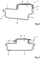
- figure 2 shows a sectional view of the in figure 1 shown component 1.
- figure 3 shows a perspective view of a further exemplary embodiment of the component 1 according to the invention for filling a liquid into a liquid container, not shown.
- the exemplary embodiment shown consists in that the projection of the cross-sectional area of the filler neck 3 onto the wall 8 is arranged in an edge region of the wall 8 .
- figure 4 shows a perspective view of a further exemplary embodiment of the component 1 according to the invention for filling a liquid into a liquid container, not shown.
- the component 1 has a one in the Figures 5 and 6 shown filling opening 2 comprising filler neck 3 and connectable to the liquid container, an in figure 5 shown outlet opening 4 comprehensive outlet section 5.
- the component 1 comprises an intermediate section 6 which is arranged between the filler neck 3 and the outlet section 5 and which, at least in its region adjoining the filler neck 3, has a widening of the component 1 in comparison to the filler neck 3 in order to calm down a liquid filled into the component 1 trains.
- the widening of the component 1 is produced by the, in particular also external, shape of the intermediate section 6, not by a variation in the material thickness of the walls of the intermediate section compared to the material thickness of the walls of the filler neck 3, since such a variation in the wall thickness is significant for the purpose of the invention would be too low.
- cover 13 is arranged, which has a in the Figures 5 and 6 locking mechanism shown is fixed to the filler neck 3.
- the cover 13 is connected via a flexible strap 14 to a ring 15 arranged captively on the filler neck 3 .
- figure 5 shows a sectional view of the in figure 4 shown component 1 according to in figure 4 shown cutting plane AA.
- the widening forms a chamber 7 which is arranged relative to the filler neck 3 in such a way that a liquid poured into the filler neck 3 is guided against the lower wall 8 of the chamber 7 which is arranged opposite the filler neck 3 .
- the projection of the cross-sectional area of the filler neck 3 onto the wall 8 is partially surrounded by an edge section of the wall 8, the projection of the cross-sectional area of the filler neck 3 onto the wall 8 being arranged in an edge region of the wall 8.
- the outlet section 5 is connected to a side 9 of the chamber 7 arranged transversely to the wall 8 .
- the Outlet section 5 is funnel-shaped in its connection area with chamber 7 and has an approximately rectangular, flattened cross section.
- figure 6 shows a sectional view of the in figure 4 shown component 1 according to in figure 4 shown cutting plane BB.
- FIG 7 shows a perspective view of a further exemplary embodiment of the component 1 according to the invention for filling a liquid into a liquid container, not shown.
- the component 1 has a one in the Figures 8 and 9 shown filling opening 2 comprising filler neck 3 and connectable to the liquid container, an outlet opening 4 comprising outlet section 5.
- the component 1 comprises an intermediate section 6 which is arranged between the filler neck 3 and the outlet section 5 and which, at least in its region adjoining the filler neck 3, has a widening of the component 1 in comparison to the filler neck 3 in order to calm down a liquid filled into the component 1 trains.
- the widening of the component 1 is produced by the, in particular also external, shape of the intermediate section 6, not by a variation in the material thickness of the walls of the intermediate section compared to the material thickness of the walls of the filler neck 3, since such a variation in the wall thickness is significant for the purpose of the invention would be too low.
- cover 13 is arranged, which has a in the Figures 8 and 9 locking mechanism shown is fixed to the filler neck 3.
- the cover 13 is connected via a flexible strap 14 to a ring 15 arranged captively on the filler neck 3 .
- figure 8 shows a sectional view of the in figure 7 shown component 1 according to in figure 7 shown cutting plane AA.
- the widening forms a chamber 7 which is arranged relative to the filler neck 3 in such a way that a liquid poured into the filler neck 3 is guided against the lower wall 8 of the chamber 7 which is opposite the filler neck 3 is arranged.
- the projection of the cross-sectional area of the filler neck 3 onto the wall 8 is partially surrounded by an edge section of the wall 8, the projection of the cross-sectional area of the filler neck 3 onto the wall 8 being arranged in an edge region of the wall 8.
- the outlet section 5 is connected to a side 9 of the chamber 7 arranged transversely to the wall 8 .
- the outlet section 5 is funnel-shaped in its connection area with the chamber 7 and has a circular cross-section.
- figure 9 shows a sectional view of the in figure 7 shown component 1 according to in figure 7 shown cutting plane BB.
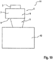
- figure 10 shows a schematic representation of an exemplary embodiment of the structural unit 11 according to the invention for receiving a liquid.
- the structural unit 11 has a liquid container 12 and a component 1 for filling the liquid into the liquid container 12 .
- the component 1 can according to the embodiments figures 1 , 3 , or 7 be trained.
Landscapes
- Engineering & Computer Science (AREA)
- Mechanical Engineering (AREA)
- Water Supply & Treatment (AREA)
- Life Sciences & Earth Sciences (AREA)
- Sustainable Development (AREA)
- Sustainable Energy (AREA)
- Chemical & Material Sciences (AREA)
- Combustion & Propulsion (AREA)
- Transportation (AREA)
- Filling Of Jars Or Cans And Processes For Cleaning And Sealing Jars (AREA)
- Containers And Packaging Bodies Having A Special Means To Remove Contents (AREA)
Description
- Die Erfindung betrifft ein Bauteil zum Einfüllen einer Flüssigkeit in einen Flüssigkeitsbehälter, aufweisend einen eine Einfüllöffnung umfassenden Einfüllstutzen und einen mit dem Flüssigkeitsbehälter verbindbaren, eine Auslassöffnung umfassenden Auslassabschnitt.
- Des Weiteren betrifft die Erfindung eine Baueinheit zur Aufnahme einer Flüssigkeit, aufweisend wenigstens einen Flüssigkeitsbehälter und zumindest ein Bauteil zum Einfüllen der Flüssigkeit in den Flüssigkeitsbehälter.
- In Fahrzeugen sind üblicherweise Flüssigkeitsbehälter zur Aufnahme von verschiedenen Flüssigkeiten vorhanden. Beispielsweise sind Flüssigkeitsbehälter zur Aufnahme von Waschwasser, Kühlflüssigkeit oder dergleichen verbaut.
- Die jeweilige Flüssigkeit kann über ein mit dem Flüssigkeitsbehälter verbundenes Einfüllbauteil in den Flüssigkeitsbehälter eingefüllt werden. Dies ist insbesondere in Zusammenhang mit einem zur Bevorratung von Waschwasser vorgesehenen Flüssigkeitsbehälter bekannt. Das Befüllen eines solchen Waschwasserbehälters wird in der Regel von einem Nutzer eines Fahrzeugs durchgeführt, kann aber auch, beispielsweise im Zuge von Wartungsarbeiten, von einem Fachpersonal durchgeführt werden.
- Bekannt ist es weiter, dass die Befüllung eines Waschwasserbehälters lediglich relativ langsam und oft auch nur mit Unterbrechungen erfolgen kann. Dies ist deshalb der Fall, da herkömmliche Einfüllbauteile in ihrem Verlauf meist einen relativ gleichbleibend kleinen, kreisförmigen Querschnitt und häufig auch Biegungen mit relativ engen Biegeradien aufweisen. Durch den Kontakt der Flüssigkeit mit der Innenwandung solcher Einfüllbauteile kommt es zu Verwirbelungen in der Flüssigkeit und zu einem Staudruck in der Flüssigkeit. Hierdurch kommt es wiederum zu einem Flüssigkeitsrückstau und zur Schaumbildung in dem Einfüllbauteil. Um dies zu verhindern, ist es erforderlich, die Flüssigkeit entweder sehr behutsam und langsam in das Einfüllbauteil einzufüllen oder einen entsprechenden Befüllvorgang zu unterbrechen, um das Auflösen des Schaums abzuwarten.
- Mit der Patentschrift
DE 102 34 105 B4 wird ein Flüssigkeitsbehälter für Fahrzeuge vorgeschlagen, welcher glucker- und spritzfrei mit einer Flüssigkeit befüllbar sein soll. - Die
WO 2013/085503 A1 beschreibt einen Einfüllstutzen mit einem Körper, der eine Öffnung, ein mit der Öffnung verbundenes Reservoir und einen Fluidkanal umfasst, der an das Reservoir angrenzt. - Aufgabe der Erfindung ist es, ein wenig zeit- und arbeitsaufwändiges Einfüllen einer Flüssigkeit in einen Flüssigkeitsbehälter zu ermöglichen.
- Diese Aufgabe wird durch ein Bauteil mit den Merkmalen gemäß Patentanspruch 1 gelöst. Des Weiteren wird die Aufgabe durch eine Baueinheit mit den Merkmalen nach Patentanspruch 7 gelöst. Vorteilhafte Ausgestaltungen sind in den abhängigen Ansprüchen wiedergegeben, welche jeweils für sich genommen oder in verschiedener Kombination miteinander einen Aspekt der Erfindung darstellen können.
- Erfindungsgemäß weist das Bauteil wenigstens einen zwischen dem Einfüllstützen und dem Auslassabschnitt angeordneten Zwischenabschnitt auf, der zumindest in seinem an den Einfüllstutzen angrenzenden Bereich im Vergleich zu dem Einfüllstutzen mindestens eine zum Beruhigen einer in das Bauteil eingefüllten Flüssigkeit eingerichtete Aufweitung des Bauteils ausbildet.
- Durch die Ausbildung der Aufweitung im Anschluss an den Einfüllstutzen kann sich eine in das Bauteil eingefüllte Flüssigkeit beruhigen, so dass es zu einem deutlich geringeren Staudruck in der Flüssigkeit kommt, als es bei herkömmlichen Einfüllbauteilen der Fall ist. Dadurch kann die Flüssigkeit schneller in das Bauteil und über dieses in einen Flüssigkeitsbehälter eingefüllt werden. Insbesondere wird durch die Aufweitung des Bauteils und die damit einhergehende Beruhigung der darin eingefüllten Flüssigkeit eine Schaumbildung innerhalb des Bauteils erfolgreich vermieden. Daher kann die Flüssigkeit ohne Unterbrechungen in das Bauteil und über dies in einen Flüssigkeitsbehälter eingefüllt werden.
- Die Aufweitung bildet eine Kammer aus, die derart relativ zu dem Einfüllstutzen angeordnet ist, dass eine in den Einfüllstutzen eingefüllte Flüssigkeit gegen eine Wand der Kammer geführt wird, die dem Einfüllstutzen gegenüberliegend angeordnet ist. Die Wand bildet hiernach eine Prallfläche, über die die Flüssigkeitsströmung umgelenkt werden kann. Hierdurch lässt sich das Bauteil an die Größe und Ausgestaltung des jeweilig verfügbaren Bauraums, in dem das Bauteil angeordnet werden soll, optimal anpassen. Die Formgebung der Kammer kann ebenfalls an die Größe und Ausgestaltung des jeweilig verfügbaren Bauraums angepasst sein.
- Eine Projektion der Querschnittsfläche des Einfüllstutzens auf die Wand ist umlaufend oder teilweise umlaufend von einem Randabschnitt der Wand umgeben. Dies kommt einer speziellen Ausgestaltung und Anordnung der Kammer mit Bezug auf den Einfüllstutzen gleich. Je größer der die Projektion der Querschnittsfläche des Einfüllstutzens auf der Wand umlaufend umgebende Randabschnitt der Wand ist, desto besser ist die Kammer für den erfindungsgemäßen Zweck ausgebildet.
- Der Auslassabschnitt ist mit einer quer zu der Wand angeordneten Seite der Kammer verbunden. Hiernach kann eine in die Aufweitung bzw. die Kammer eingefüllte Flüssigkeit im Wesentlichen seitlich aus der Kammer abgeleitet werden.
- Eine weitere vorteilhafte Ausgestaltung sieht vor, dass die Projektion der Querschnittsfläche des Einfüllstutzens auf die Wand mittig an der Wand angeordnet ist.
- Es wird weiter als vorteilhaft erachtet, wenn die Projektion der Querschnittsfläche des Einfüllstutzens auf die Wand in einem Randbereich der Wand angeordnet ist. Diese außermittige Anordnung der Projektionsfläche kann alternativ zu der vorgenannten mittigen Anordnung der Projektionsfläche gewählt werden. Die optimale Anordnung der Projektionsfläche an der Wand ist vorzugsweise unter Berücksichtigung der Größe und der Ausgestaltung des jeweilig zur Verfügung stehenden Bauraums ausgewählt.
- Nach einer weiteren vorteilhaften Ausgestaltung ist der Auslassabschnitt trichterförmig ausgebildet. Die über den Einfüllstutzen in das Bauteil eingefüllte Flüssigkeit, welche sich nach dem Passieren des Zwischenabschnitts beruhigt hat, kann so einer Befüllöffnung in einem Flüssigkeitsbehälter zugeführt werden. Über den trichterförmigen Auslassabschnitt kann die beruhigte Flüssigkeit schnell und mit relativ hoher Geschwindigkeit einem Flüssigkeitsbehälter zugeführt werden.
- Weiter wird vorgeschlagen, dass der Auslassabschnitt zumindest teilweise einen kreisförmigen Querschnitt aufweist. Dies entspricht einer üblichen Ausgestaltung, so dass das Bauteil auf einfache Art und Weise mit einem herkömmlichen Flüssigkeitsbehälter verbunden werden kann, ohne dass an dem Flüssigkeitsbehälter bauliche Veränderungen vorgenommen werden müssen.
- Ferner wird es als vorteilhaft erachtet, wenn der Auslassabschnitt zumindest teilweise einen rechteckigen Querschnitt aufweist. Welche Form für den Querschnitt des Auslassabschnitts gewählt wird, hängt von den jeweiligen Gegebenheiten ab. Bei einem Auslassabschnitt mit rechteckigem Querschnitt fliest die Flüssigkeit vorzugsweise im Wesentlichen über eine der langen Seitenflächen des Auslassabschnitts hinweg, so dass sich die Flüssigkeit auch während ihres Passierens durch den Auslassabschnitt weiter beruhigen kann.
- Weiter erfindungsgemäß ist das Bauteil der Baueinheit gemäß einer der vorgenannten Ausgestaltungen oder einer beliebigen Kombination derselben ausgebildet. Damit sind die oben mit Bezug auf das Bauteil genannten Vorteile verbunden. Der Flüssigkeitsbehälter kann zur Aufnahme von Waschwasser, Kühlflüssigkeit oder dergleichen ausgebildet sein
- Weitere Einzelheiten, Merkmale und Vorteile der Erfindung ergeben sich aus der nachfolgenden Beschreibung und den Figuren. Es zeigen:
- Figur 1
- eine perspektivische Darstellung einer beispielhaften Ausführungsform des erfindungsgemäßen Bauteils,
- Figur 2:
- eine Schnittdarstellung des in
Figur 1 gezeigten Bauteils, - Figur 3:
- eine perspektivische Darstellung einer weiteren beispielhaften Ausführungsform des erfindungsgemäßen Bauteils,
- Figur 4
- eine perspektivische Darstellung einer weiteren beispielhaften Ausführungsform des erfindungsgemäßen Bauteils,
- Figur 5
- eine Schnittdarstellung des in
Figur 4 gezeigten Bauteils, - Figur 6
- eine weitere Schnittdarstellung des in
Figur 4 gezeigten Bauteils, - Figur 7
- eine perspektivische Darstellung einer weiteren beispielhaften Ausführungsform des erfindungsgemäßen Bauteils,
- Figur 8
- eine Schnittdarstellung des in
Figur 7 gezeigten Bauteils, - Figur 9
- eine weitere Schnittdarstellung des in
Figur 7 gezeigten Bauteils, und - Figur 10:
- eine schematische Darstellung einer beispielhaften Ausführungsform der erfindungsgemäßen Baueinheit.
-
Figur 1 zeigt eine perspektivische Darstellung einer beispielhaften Ausführungsform des erfindungsgemäßen Bauteils 1 zum Einfüllen einer Flüssigkeit in einen nicht gezeigten Flüssigkeitsbehälter. Das Bauteil 1 weist einen eine Einfüllöffnung 2 umfassenden Einfüllstutzen 3 und einen mit dem Flüssigkeitsbehälter verbindbaren, eine Auslassöffnung 4 umfassenden Auslassabschnitt 5 auf. Des Weiteren umfasst das Bauteil 1 einen zwischen dem Einfüllstützen 3 und dem Auslassabschnitt 5 angeordneten Zwischenabschnitt 6, der zumindest in seinem an den Einfüllstutzen 3 angrenzenden Bereich im Vergleich zu dem Einfüllstutzen 3 eine zum Beruhigen einer in das Bauteil 1 eingefüllten Flüssigkeit eingerichtete Aufweitung des Bauteils 1 ausbildet. - Die Aufweitung bildet eine Kammer 7 aus, die derart relativ zu dem Einfüllstutzen 3 angeordnet ist, dass eine in den Einfüllstutzen 3 eingefüllte Flüssigkeit gegen die dem Betrachter abgewandte untere Wand 8 der Kammer 7 geführt wird, die dem Einfüllstutzen 3 gegenüberliegend angeordnet ist. Wie sich aus
Figur 1 ergibt, ist die Projektion der Querschnittsfläche des Einfüllstutzens 3 auf die Wand 8 umlaufend von einem Randabschnitt der Wand 8 umgeben, wobei die Projektion der Querschnittsfläche des Einfüllstutzens 3 auf die Wand 8 mittig an der Wand 8 angeordnet ist. Seitlich an der Kammer 7 sind Befestigungslaschen 10 angeordnet, über die das Bauteil 1 an einer nicht gezeigten Karosserie eines Fahrzeugs befestigbar ist. - Der Auslassabschnitt 5 ist mit einer quer zu der Wand 8 angeordneten Seite 9 der Kammer 7 verbunden. Der Auslassabschnitt 5 ist in seinem Verbindungsbereich mit der Kammer 7 trichterförmig ausgebildet und weist einen rechteckigen Querschnitt auf.
-
Figur 2 zeigt eine Schnittdarstellung des inFigur 1 gezeigten Bauteils 1. -
Figur 3 zeigt eine perspektivische Darstellung einer weiteren beispielhaften Ausführungsform des erfindungsgemäßen Bauteils 1 zum Einfüllen einer Flüssigkeit in einen nicht gezeigten Flüssigkeitsbehälter. Ein wesentlicher Unterschied zu dem in denFiguren 1 und2 gezeigten Ausführungsbeispiel besteht darin, dass die Projektion der Querschnittsfläche des Einfüllstutzens 3 auf die Wand 8 in einem Randbereich der Wand 8 angeordnet ist. -
Figur 4 zeigt eine perspektivische Darstellung einer weiteren beispielhaften Ausführungsform des erfindungsgemäßen Bauteils 1 zum Einfüllen einer Flüssigkeit in einen nicht gezeigten Flüssigkeitsbehälter. Das Bauteil 1 weist einen eine in denFiguren 5 und 6 gezeigte Einfüllöffnung 2 umfassenden Einfüllstutzen 3 und einen mit dem Flüssigkeitsbehälter verbindbaren, eine inFigur 5 gezeigte Auslassöffnung 4 umfassenden Auslassabschnitt 5 auf. Des Weiteren umfasst das Bauteil 1 einen zwischen dem Einfüllstützen 3 und dem Auslassabschnitt 5 angeordneten Zwischenabschnitt 6, der zumindest in seinem an den Einfüllstutzen 3 angrenzenden Bereich im Vergleich zu dem Einfüllstutzen 3 eine zum Beruhigen einer in das Bauteil 1 eingefüllten Flüssigkeit eingerichtete Aufweitung des Bauteils 1 ausbildet. Die Aufweitung des Bauteils 1 wird durch die, insbesondere auch äußere, Formgebung des Zwischenabschnitts 6 erzeugt, nicht durch eine Variation der Materialstärke der Wandungen des Zwischenabschnitts im Vergleich zur Materialstärke der Wandungen des Einfüllstutzens 3, da eine solche Variation der Wandstärke für den erfindungsgemäßen Zweck deutlich zu gering ausfallen würde. An dem Einfüllstutzen 3 ist ein in seiner Schließstellung befindlicher Deckel 13 angeordnet, welcher über einen in denFiguren 5 und 6 gezeigten Rastmechanismus an dem Einfüllstutzen 3 festgelegt ist. Der Deckel 13 ist über eine flexible Lasche 14 mit einem unverlierbar an dem Einfüllstutzen 3 angeordneten Ring 15 verbunden. -
Figur 5 zeigt eine Schnittdarstellung des inFigur 4 gezeigten Bauteils 1 gemäß der inFigur 4 gezeigten Schnittebene A-A. Die Aufweitung bildet eine Kammer 7 aus, die derart relativ zu dem Einfüllstutzen 3 angeordnet ist, dass eine in den Einfüllstutzen 3 eingefüllte Flüssigkeit gegen die untere Wand 8 der Kammer 7 geführt wird, die dem Einfüllstutzen 3 gegenüberliegend angeordnet ist. Wie sich ausFigur 5 ergibt, ist die Projektion der Querschnittsfläche des Einfüllstutzens 3 auf die Wand 8 teilweise umlaufend von einem Randabschnitt der Wand 8 umgeben, wobei die Projektion der Querschnittsfläche des Einfüllstutzens 3 auf die Wand 8 in einem Randbereich der Wand 8 angeordnet ist. Der Auslassabschnitt 5 ist mit einer quer zu der Wand 8 angeordneten Seite 9 der Kammer 7 verbunden. Der Auslassabschnitt 5 ist in seinem Verbindungsbereich mit der Kammer 7 trichterförmig ausgebildet und weist einen annähernd rechteckigen, abgeflachten Querschnitt auf. -
Figur 6 zeigt eine Schnittdarstellung des inFigur 4 gezeigten Bauteils 1 gemäß der inFigur 4 gezeigten Schnittebene B-B. -
Figur 7 zeigt eine perspektivische Darstellung einer weiteren beispielhaften Ausführungsform des erfindungsgemäßen Bauteils 1 zum Einfüllen einer Flüssigkeit in einen nicht gezeigten Flüssigkeitsbehälter. Das Bauteil 1 weist einen eine in denFiguren 8 und 9 gezeigte Einfüllöffnung 2 umfassenden Einfüllstutzen 3 und einen mit dem Flüssigkeitsbehälter verbindbaren, eine Auslassöffnung 4 umfassenden Auslassabschnitt 5 auf. Des Weiteren umfasst das Bauteil 1 einen zwischen dem Einfüllstützen 3 und dem Auslassabschnitt 5 angeordneten Zwischenabschnitt 6, der zumindest in seinem an den Einfüllstutzen 3 angrenzenden Bereich im Vergleich zu dem Einfüllstutzen 3 eine zum Beruhigen einer in das Bauteil 1 eingefüllten Flüssigkeit eingerichtete Aufweitung des Bauteils 1 ausbildet. Die Aufweitung des Bauteils 1 wird durch die, insbesondere auch äußere, Formgebung des Zwischenabschnitts 6 erzeugt, nicht durch eine Variation der Materialstärke der Wandungen des Zwischenabschnitts im Vergleich zur Materialstärke der Wandungen des Einfüllstutzens 3, da eine solche Variation der Wandstärke für den erfindungsgemäßen Zweck deutlich zu gering ausfallen würde. An dem Einfüllstutzen 3 ist ein in seiner Schließstellung befindlicher Deckel 13 angeordnet, welcher über einen in denFiguren 8 und 9 gezeigten Rastmechanismus an dem Einfüllstutzen 3 festgelegt ist. Der Deckel 13 ist über eine flexible Lasche 14 mit einem unverlierbar an dem Einfüllstutzen 3 angeordneten Ring 15 verbunden. -
Figur 8 zeigt eine Schnittdarstellung des inFigur 7 gezeigten Bauteils 1 gemäß der inFigur 7 gezeigten Schnittebene A-A. Die Aufweitung bildet eine Kammer 7 aus, die derart relativ zu dem Einfüllstutzen 3 angeordnet ist, dass eine in den Einfüllstutzen 3 eingefüllte Flüssigkeit gegen die untere Wand 8 der Kammer 7 geführt wird, die dem Einfüllstutzen 3 gegenüberliegend angeordnet ist. Wie sich ausFigur 8 ergibt, ist die Projektion der Querschnittsfläche des Einfüllstutzens 3 auf die Wand 8 teilweise umlaufend von einem Randabschnitt der Wand 8 umgeben, wobei die Projektion der Querschnittsfläche des Einfüllstutzens 3 auf die Wand 8 in einem Randbereich der Wand 8 angeordnet ist. Der Auslassabschnitt 5 ist mit einer quer zu der Wand 8 angeordneten Seite 9 der Kammer 7 verbunden. Der Auslassabschnitt 5 ist in seinem Verbindungsbereich mit der Kammer 7 trichterförmig ausgebildet und weist einen kreisförmigen Querschnitt auf. -
Figur 9 zeigt eine Schnittdarstellung des inFigur 7 gezeigten Bauteils 1 gemäß der inFigur 7 gezeigten Schnittebene B-B. -
Figur 10 zeigt eine schematische Darstellung einer beispielhaften Ausführungsform der erfindungsgemäßen Baueinheit 11 zur Aufnahme einer Flüssigkeit. Die Baueinheit 11 weist einen Flüssigkeitsbehälter 12 und ein Bauteil 1 zum Einfüllen der Flüssigkeit in den Flüssigkeitsbehälter 12 auf. Das Bauteil 1 kann gemäß den Ausführungsbeispielen derFiguren 1 ,3 , oder7 ausgebildet sein. -
- 1
- Bauteil
- 2
- Einfüllöffnung
- 3
- Einfüllstutzen
- 4
- Auslassöffnung
- 5
- Auslassabschnitt
- 6
- Zwischenabschnitt
- 7
- Kammer
- 8
- Wand
- 9
- Seite
- 10
- Befestigungslasche
- 11
- Baueinheit
- 12
- Flüssigkeitsbehälter
- 13
- Deckel
- 14
- Lasche
- 15
- Ring
Claims (7)
- Bauteil (1) zum Einfüllen einer Flüssigkeit in einen Flüssigkeitsbehälter (12), aufweisend einen eine Einfüllöffnung (2) umfassenden Einfüllstutzen (3) und einen mit dem Flüssigkeitsbehälter (12) verbindbaren, eine Auslassöffnung (4) umfassenden Auslassabschnitt (5), wobei wenigstens ein zwischen dem Einfüllstützen (3) und dem Auslassabschnitt (5) angeordneter Zwischenabschnitt (6) vorgesehen ist, der zumindest in seinem an den Einfüllstutzen (3) angrenzenden Bereich im Vergleich zu dem Einfüllstutzen (3) mindestens eine Aufweitung des Bauteils (1) ausbildet, wobei die Aufweitung eine Kammer (7) zum Beruhigen einer in das Bauteil (1) eingefüllten Flüssigkeit ausbildet, die derart relativ zu dem Einfüllstutzen (3) angeordnet ist, dass eine in den Einfüllstutzen (3) eingefüllte Flüssigkeit gegen eine untere Wand (8) der Kammer (7) geführt wird, die dem Einfüllstutzen (3) gegenüberliegend angeordnet ist und eine Prallfläche zur Umlenkung der Flüssigkeitsströmung bildet, wobei eine Projektion der Querschnittsfläche des Einfüllstutzens (3) auf die Wand (8) umlaufend oder teilweise umlaufend von einem Randabschnitt der Wand (8) umgeben ist, dadurch gekennzeichnet, dass der Auslassabschnitt (5) mit einer quer zu der Wand (8) angeordneten Seite (9) der Kammer (7) verbunden ist.
- Bauteil (1) nach Anspruch 1, dadurch gekennzeichnet, dass die Projektion der Querschnittsfläche des Einfüllstutzens (3) auf die Wand (8) mittig an der Wand (8) angeordnet ist.
- Bauteil (1) nach Anspruch 1, dadurch gekennzeichnet, dass die Projektion der Querschnittsfläche des Einfüllstutzens (3) auf die Wand (8) in einem Randbereich der Wand (8) angeordnet ist.
- Bauteil (1) nach einem der Ansprüche 1 bis 3, dadurch gekennzeichnet, dass der Auslassabschnitt (5) trichterförmig ausgebildet ist.
- Bauteil (1) nach einem der Ansprüche 1 bis 4, dadurch gekennzeichnet, dass der Auslassabschnitt (5) zumindest teilweise einen kreisförmigen Querschnitt aufweist.
- Bauteil (1) nach einem der Ansprüche 1 bis 4, dadurch gekennzeichnet, dass der Auslassabschnitt (5) zumindest teilweise einen rechteckigen Querschnitt aufweist.
- Baueinheit (11) zur Aufnahme einer Flüssigkeit, aufweisend wenigstens einen Flüssigkeitsbehälter (12) und zumindest ein Bauteil (1) zum Einfüllen der Flüssigkeit in den Flüssigkeitsbehälter (12), dadurch gekennzeichnet, dass das Bauteil (1) gemäß einem der Ansprüche 1 bis 6 ausgebildet ist.
Applications Claiming Priority (2)
| Application Number | Priority Date | Filing Date | Title |
|---|---|---|---|
| DE102013211958.5A DE102013211958A1 (de) | 2013-06-24 | 2013-06-24 | Bauteil zum Einfüllen einer Flüssigkeit in einen Flüssigkeitsbehälter |
| PCT/EP2014/062791 WO2014206824A1 (de) | 2013-06-24 | 2014-06-18 | Bauteil zum einfüllen einer flüssigkeit in einen flüssigkeitsbehälter |
Publications (2)
| Publication Number | Publication Date |
|---|---|
| EP3013653A1 EP3013653A1 (de) | 2016-05-04 |
| EP3013653B1 true EP3013653B1 (de) | 2022-04-06 |
Family
ID=50972722
Family Applications (1)
| Application Number | Title | Priority Date | Filing Date |
|---|---|---|---|
| EP14730920.7A Active EP3013653B1 (de) | 2013-06-24 | 2014-06-18 | Bauteil zum einfüllen einer flüssigkeit in einen flüssigkeitsbehälter |
Country Status (5)
| Country | Link |
|---|---|
| US (1) | US11292436B2 (de) |
| EP (1) | EP3013653B1 (de) |
| CN (1) | CN105339219B (de) |
| DE (1) | DE102013211958A1 (de) |
| WO (1) | WO2014206824A1 (de) |
Cited By (1)
| Publication number | Priority date | Publication date | Assignee | Title |
|---|---|---|---|---|
| DE102023205920A1 (de) * | 2023-06-23 | 2024-12-24 | Stellantis Auto Sas | Wischwassereinfüllstutzen mit Arretierung |
Families Citing this family (2)
| Publication number | Priority date | Publication date | Assignee | Title |
|---|---|---|---|---|
| EP3693234B1 (de) * | 2019-02-11 | 2022-04-27 | FCA Italy S.p.A. | Kraftfahrzeug mit einer befüllungsvorrichtung zum befüllen eines behälters mit wischerflüssigkeit |
| DE102021111994A1 (de) | 2021-05-07 | 2022-11-10 | Bayerische Motoren Werke Aktiengesellschaft | Flüssigkeitsbehälter mit einem Einfüllstutzen |
Citations (1)
| Publication number | Priority date | Publication date | Assignee | Title |
|---|---|---|---|---|
| WO2013085503A1 (en) * | 2011-12-07 | 2013-06-13 | Toledo Molding & Die, Inc. | Filler neck for an automotive fluid container |
Family Cites Families (19)
| Publication number | Priority date | Publication date | Assignee | Title |
|---|---|---|---|---|
| DE1784086U (de) * | 1958-07-16 | 1959-02-26 | Westfaelische Metall Industrie | Behaelterverschluss fuer scheibenwascher an kraftfahrzeugen. |
| US3991792A (en) * | 1975-02-03 | 1976-11-16 | Kettler William C | Anti-siphon gasoline tank |
| US5226574A (en) * | 1991-08-16 | 1993-07-13 | Durinzi Jr Armando F | Portable dispensing container for liquid fuel |
| JP2986419B2 (ja) * | 1997-02-25 | 1999-12-06 | 本田技研工業株式会社 | 燃料注入装置 |
| DE20023339U1 (de) * | 1999-11-30 | 2003-09-18 | McCord Winn Textron, Manchester, N.H. | Raumausnutzung/Bauteilintegration unter Verwendung der Blasformtechnologie |
| US6588459B2 (en) * | 1999-12-03 | 2003-07-08 | Shelby Enterprises, Inc. | Fuel tank filler neck and method of manufacturing same |
| US6223793B1 (en) * | 2000-02-16 | 2001-05-01 | Daimlerchrysler Corporation | Automotive vehicle remote fill reservoir |
| DE10042529A1 (de) * | 2000-08-30 | 2002-03-21 | Kautex Textron Gmbh & Co Kg | Kraftstofftank |
| DE10050214B4 (de) * | 2000-10-11 | 2012-06-28 | Volkswagen Ag | Waschflüssigkeitsbehälter für eine Scheibenreinigungsanlage in einem Fahrzeug |
| DE20022285U1 (de) * | 2000-11-22 | 2001-07-12 | Gassner, Herbert, 85250 Altomünster | Scheibenwaschwasser-Rückgewinnungseinrichtung für Autos |
| JP3897990B2 (ja) * | 2001-04-17 | 2007-03-28 | 自動車電機工業株式会社 | ウォッシャタンク |
| FR2824515B1 (fr) * | 2001-05-11 | 2004-03-12 | Renault | Reservoir de lave-glace traversant une tole d'automobile |
| DE10234105B4 (de) | 2002-07-26 | 2006-01-26 | Daimlerchrysler Ag | Flüssigkeitsbehälter für Fahrzeuge |
| US7303089B2 (en) * | 2004-10-21 | 2007-12-04 | Keller Russell D | Anti-siphon fuel cap and filler tube assembly |
| JP2010089702A (ja) * | 2008-10-10 | 2010-04-22 | Toyota Auto Body Co Ltd | インレット及びこれを備えたウォッシャタンク |
| WO2012037662A2 (en) * | 2010-09-23 | 2012-03-29 | Gorecki Jarek R | Reservoir with vent |
| CN104736369B (zh) * | 2012-08-20 | 2017-12-08 | 拉瓦尔A.C.S.公司 | 交通工具燃油附件 |
| JP6154115B2 (ja) * | 2012-10-12 | 2017-06-28 | フタバ産業株式会社 | フューエルインレット |
| CN104955669B (zh) * | 2012-12-04 | 2017-10-20 | 全耐塑料高级创新研究公司 | 填充口颈总成以及制造这种填充口颈总成的方法 |
-
2013
- 2013-06-24 DE DE102013211958.5A patent/DE102013211958A1/de not_active Withdrawn
-
2014
- 2014-06-18 WO PCT/EP2014/062791 patent/WO2014206824A1/de not_active Ceased
- 2014-06-18 CN CN201480036010.9A patent/CN105339219B/zh active Active
- 2014-06-18 EP EP14730920.7A patent/EP3013653B1/de active Active
-
2015
- 2015-12-23 US US14/757,454 patent/US11292436B2/en active Active
Patent Citations (1)
| Publication number | Priority date | Publication date | Assignee | Title |
|---|---|---|---|---|
| WO2013085503A1 (en) * | 2011-12-07 | 2013-06-13 | Toledo Molding & Die, Inc. | Filler neck for an automotive fluid container |
Cited By (1)
| Publication number | Priority date | Publication date | Assignee | Title |
|---|---|---|---|---|
| DE102023205920A1 (de) * | 2023-06-23 | 2024-12-24 | Stellantis Auto Sas | Wischwassereinfüllstutzen mit Arretierung |
Also Published As
| Publication number | Publication date |
|---|---|
| CN105339219B (zh) | 2017-08-29 |
| WO2014206824A1 (de) | 2014-12-31 |
| DE102013211958A1 (de) | 2014-12-24 |
| US11292436B2 (en) | 2022-04-05 |
| US20160152212A1 (en) | 2016-06-02 |
| CN105339219A (zh) | 2016-02-17 |
| EP3013653A1 (de) | 2016-05-04 |
Similar Documents
| Publication | Publication Date | Title |
|---|---|---|
| EP2262738B1 (de) | Behälter für die filtration von flüssigkeit mit auslassfenster für luft | |
| WO2010102616A1 (de) | Ölbehälter | |
| EP3052407B1 (de) | Kapsel und system zur zubereitung eines flüssigen lebensmittels | |
| EP2606782A1 (de) | Kaffee-/Espressomaschine mit einer Milchschaumerzeugungseinrichtung für Cappuccino | |
| DE20320605U1 (de) | Padträger für eine Getränkemaschine, Schaumeinheit und Getränkemaschine mit einem derartigen Padträger zum Bereiten eines Getränkes mit einer Schaumeinheit unter Verwendung eines derartigen Padträgers | |
| EP3013653B1 (de) | Bauteil zum einfüllen einer flüssigkeit in einen flüssigkeitsbehälter | |
| WO2012031706A1 (de) | Ölablassvorrichtung | |
| EP3055156B1 (de) | Einfüllstutzen für einen kraftfahrzeug-betriebsflüssigkeitsbehälter | |
| DE202017103843U1 (de) | Motorhaubenanordnung, die einen Flüssigkeitsbehälter einbindet | |
| DE102004022096B3 (de) | Füllventil, ausgestattet mit einer Gassperre mit Drallwirkung | |
| EP3368364B1 (de) | Kraftstoffbehälter mit zusatzreservevolumen | |
| EP3645148B1 (de) | Fahrzeugbehandlungseinrichtung mit einer schaumerzeugungseinrichtung | |
| DE102012220991A1 (de) | Vorrichtung zum Emulgieren einer Mischung aus Luft, Dampf und Milch | |
| EP3199715B1 (de) | Überlauf für ein becken, insbesondere spülenbecken | |
| EP2216226B1 (de) | Schienenfahrzeug mit Fahrzeugtürdichtung | |
| DE202011109523U1 (de) | Filter zum Einsetzen in einen Einfüllstutzen eines Behälters | |
| EP4001524A1 (de) | Strahlregler | |
| DE102005041813B4 (de) | Vorrichtung zum Verringern der Fließgeschwindigkeit einer Hydraulikflüssigkeit für ein hydraulisches System | |
| EP2878247B1 (de) | Rührtopf mit einem einen Grenzschicht ablösend oberflächenstrukturierten Lagerkörper aufweisenden Rührwerk | |
| DE10210821B4 (de) | Belaugungsstation für Backwaren, insbesondere für Gärgut | |
| EP4574696A1 (de) | Kunststoffkanister zur aufnahme einer flüssigkeit | |
| DE102012004424A1 (de) | Brause | |
| DE102004025059B4 (de) | Behälter | |
| EP3166871B1 (de) | Kapsel mit einem vorzugsweise rotationssymmetrisch ausgebildeten kapselkörper | |
| DE202011102814U1 (de) | Freier Auslauf mit Injektor in Doppelkammer |
Legal Events
| Date | Code | Title | Description |
|---|---|---|---|
| PUAI | Public reference made under article 153(3) epc to a published international application that has entered the european phase |
Free format text: ORIGINAL CODE: 0009012 |
|
| 17P | Request for examination filed |
Effective date: 20151123 |
|
| AK | Designated contracting states |
Kind code of ref document: A1 Designated state(s): AL AT BE BG CH CY CZ DE DK EE ES FI FR GB GR HR HU IE IS IT LI LT LU LV MC MK MT NL NO PL PT RO RS SE SI SK SM TR |
|
| AX | Request for extension of the european patent |
Extension state: BA ME |
|
| DAX | Request for extension of the european patent (deleted) | ||
| STAA | Information on the status of an ep patent application or granted ep patent |
Free format text: STATUS: EXAMINATION IS IN PROGRESS |
|
| 17Q | First examination report despatched |
Effective date: 20190403 |
|
| GRAP | Despatch of communication of intention to grant a patent |
Free format text: ORIGINAL CODE: EPIDOSNIGR1 |
|
| STAA | Information on the status of an ep patent application or granted ep patent |
Free format text: STATUS: GRANT OF PATENT IS INTENDED |
|
| INTG | Intention to grant announced |
Effective date: 20211006 |
|
| GRAJ | Information related to disapproval of communication of intention to grant by the applicant or resumption of examination proceedings by the epo deleted |
Free format text: ORIGINAL CODE: EPIDOSDIGR1 |
|
| STAA | Information on the status of an ep patent application or granted ep patent |
Free format text: STATUS: EXAMINATION IS IN PROGRESS |
|
| GRAS | Grant fee paid |
Free format text: ORIGINAL CODE: EPIDOSNIGR3 |
|
| STAA | Information on the status of an ep patent application or granted ep patent |
Free format text: STATUS: GRANT OF PATENT IS INTENDED |
|
| GRAP | Despatch of communication of intention to grant a patent |
Free format text: ORIGINAL CODE: EPIDOSNIGR1 |
|
| INTC | Intention to grant announced (deleted) | ||
| GRAA | (expected) grant |
Free format text: ORIGINAL CODE: 0009210 |
|
| STAA | Information on the status of an ep patent application or granted ep patent |
Free format text: STATUS: THE PATENT HAS BEEN GRANTED |
|
| INTG | Intention to grant announced |
Effective date: 20220222 |
|
| AK | Designated contracting states |
Kind code of ref document: B1 Designated state(s): AL AT BE BG CH CY CZ DE DK EE ES FI FR GB GR HR HU IE IS IT LI LT LU LV MC MK MT NL NO PL PT RO RS SE SI SK SM TR |
|
| REG | Reference to a national code |
Ref country code: GB Ref legal event code: FG4D Free format text: NOT ENGLISH |
|
| REG | Reference to a national code |
Ref country code: CH Ref legal event code: EP |
|
| REG | Reference to a national code |
Ref country code: AT Ref legal event code: REF Ref document number: 1481066 Country of ref document: AT Kind code of ref document: T Effective date: 20220415 |
|
| REG | Reference to a national code |
Ref country code: DE Ref legal event code: R096 Ref document number: 502014016186 Country of ref document: DE |
|
| REG | Reference to a national code |
Ref country code: IE Ref legal event code: FG4D Free format text: LANGUAGE OF EP DOCUMENT: GERMAN |
|
| REG | Reference to a national code |
Ref country code: LT Ref legal event code: MG9D |
|
| REG | Reference to a national code |
Ref country code: NL Ref legal event code: MP Effective date: 20220406 |
|
| PG25 | Lapsed in a contracting state [announced via postgrant information from national office to epo] |
Ref country code: NL Free format text: LAPSE BECAUSE OF FAILURE TO SUBMIT A TRANSLATION OF THE DESCRIPTION OR TO PAY THE FEE WITHIN THE PRESCRIBED TIME-LIMIT Effective date: 20220406 |
|
| PG25 | Lapsed in a contracting state [announced via postgrant information from national office to epo] |
Ref country code: SE Free format text: LAPSE BECAUSE OF FAILURE TO SUBMIT A TRANSLATION OF THE DESCRIPTION OR TO PAY THE FEE WITHIN THE PRESCRIBED TIME-LIMIT Effective date: 20220406 Ref country code: PT Free format text: LAPSE BECAUSE OF FAILURE TO SUBMIT A TRANSLATION OF THE DESCRIPTION OR TO PAY THE FEE WITHIN THE PRESCRIBED TIME-LIMIT Effective date: 20220808 Ref country code: NO Free format text: LAPSE BECAUSE OF FAILURE TO SUBMIT A TRANSLATION OF THE DESCRIPTION OR TO PAY THE FEE WITHIN THE PRESCRIBED TIME-LIMIT Effective date: 20220706 Ref country code: LT Free format text: LAPSE BECAUSE OF FAILURE TO SUBMIT A TRANSLATION OF THE DESCRIPTION OR TO PAY THE FEE WITHIN THE PRESCRIBED TIME-LIMIT Effective date: 20220406 Ref country code: HR Free format text: LAPSE BECAUSE OF FAILURE TO SUBMIT A TRANSLATION OF THE DESCRIPTION OR TO PAY THE FEE WITHIN THE PRESCRIBED TIME-LIMIT Effective date: 20220406 Ref country code: GR Free format text: LAPSE BECAUSE OF FAILURE TO SUBMIT A TRANSLATION OF THE DESCRIPTION OR TO PAY THE FEE WITHIN THE PRESCRIBED TIME-LIMIT Effective date: 20220707 Ref country code: FI Free format text: LAPSE BECAUSE OF FAILURE TO SUBMIT A TRANSLATION OF THE DESCRIPTION OR TO PAY THE FEE WITHIN THE PRESCRIBED TIME-LIMIT Effective date: 20220406 Ref country code: ES Free format text: LAPSE BECAUSE OF FAILURE TO SUBMIT A TRANSLATION OF THE DESCRIPTION OR TO PAY THE FEE WITHIN THE PRESCRIBED TIME-LIMIT Effective date: 20220406 Ref country code: BG Free format text: LAPSE BECAUSE OF FAILURE TO SUBMIT A TRANSLATION OF THE DESCRIPTION OR TO PAY THE FEE WITHIN THE PRESCRIBED TIME-LIMIT Effective date: 20220706 |
|
| PG25 | Lapsed in a contracting state [announced via postgrant information from national office to epo] |
Ref country code: RS Free format text: LAPSE BECAUSE OF FAILURE TO SUBMIT A TRANSLATION OF THE DESCRIPTION OR TO PAY THE FEE WITHIN THE PRESCRIBED TIME-LIMIT Effective date: 20220406 Ref country code: PL Free format text: LAPSE BECAUSE OF FAILURE TO SUBMIT A TRANSLATION OF THE DESCRIPTION OR TO PAY THE FEE WITHIN THE PRESCRIBED TIME-LIMIT Effective date: 20220406 Ref country code: LV Free format text: LAPSE BECAUSE OF FAILURE TO SUBMIT A TRANSLATION OF THE DESCRIPTION OR TO PAY THE FEE WITHIN THE PRESCRIBED TIME-LIMIT Effective date: 20220406 Ref country code: IS Free format text: LAPSE BECAUSE OF FAILURE TO SUBMIT A TRANSLATION OF THE DESCRIPTION OR TO PAY THE FEE WITHIN THE PRESCRIBED TIME-LIMIT Effective date: 20220806 |
|
| REG | Reference to a national code |
Ref country code: DE Ref legal event code: R097 Ref document number: 502014016186 Country of ref document: DE |
|
| PG25 | Lapsed in a contracting state [announced via postgrant information from national office to epo] |
Ref country code: SM Free format text: LAPSE BECAUSE OF FAILURE TO SUBMIT A TRANSLATION OF THE DESCRIPTION OR TO PAY THE FEE WITHIN THE PRESCRIBED TIME-LIMIT Effective date: 20220406 Ref country code: SK Free format text: LAPSE BECAUSE OF FAILURE TO SUBMIT A TRANSLATION OF THE DESCRIPTION OR TO PAY THE FEE WITHIN THE PRESCRIBED TIME-LIMIT Effective date: 20220406 Ref country code: RO Free format text: LAPSE BECAUSE OF FAILURE TO SUBMIT A TRANSLATION OF THE DESCRIPTION OR TO PAY THE FEE WITHIN THE PRESCRIBED TIME-LIMIT Effective date: 20220406 Ref country code: MC Free format text: LAPSE BECAUSE OF FAILURE TO SUBMIT A TRANSLATION OF THE DESCRIPTION OR TO PAY THE FEE WITHIN THE PRESCRIBED TIME-LIMIT Effective date: 20220406 Ref country code: EE Free format text: LAPSE BECAUSE OF FAILURE TO SUBMIT A TRANSLATION OF THE DESCRIPTION OR TO PAY THE FEE WITHIN THE PRESCRIBED TIME-LIMIT Effective date: 20220406 Ref country code: DK Free format text: LAPSE BECAUSE OF FAILURE TO SUBMIT A TRANSLATION OF THE DESCRIPTION OR TO PAY THE FEE WITHIN THE PRESCRIBED TIME-LIMIT Effective date: 20220406 Ref country code: CZ Free format text: LAPSE BECAUSE OF FAILURE TO SUBMIT A TRANSLATION OF THE DESCRIPTION OR TO PAY THE FEE WITHIN THE PRESCRIBED TIME-LIMIT Effective date: 20220406 |
|
| REG | Reference to a national code |
Ref country code: CH Ref legal event code: PL |
|
| PLBE | No opposition filed within time limit |
Free format text: ORIGINAL CODE: 0009261 |
|
| STAA | Information on the status of an ep patent application or granted ep patent |
Free format text: STATUS: NO OPPOSITION FILED WITHIN TIME LIMIT |
|
| REG | Reference to a national code |
Ref country code: BE Ref legal event code: MM Effective date: 20220630 |
|
| 26N | No opposition filed |
Effective date: 20230110 |
|
| PG25 | Lapsed in a contracting state [announced via postgrant information from national office to epo] |
Ref country code: AL Free format text: LAPSE BECAUSE OF FAILURE TO SUBMIT A TRANSLATION OF THE DESCRIPTION OR TO PAY THE FEE WITHIN THE PRESCRIBED TIME-LIMIT Effective date: 20220406 |
|
| PG25 | Lapsed in a contracting state [announced via postgrant information from national office to epo] |
Ref country code: LU Free format text: LAPSE BECAUSE OF NON-PAYMENT OF DUE FEES Effective date: 20220618 Ref country code: LI Free format text: LAPSE BECAUSE OF NON-PAYMENT OF DUE FEES Effective date: 20220630 Ref country code: IE Free format text: LAPSE BECAUSE OF NON-PAYMENT OF DUE FEES Effective date: 20220618 Ref country code: CH Free format text: LAPSE BECAUSE OF NON-PAYMENT OF DUE FEES Effective date: 20220630 |
|
| PG25 | Lapsed in a contracting state [announced via postgrant information from national office to epo] |
Ref country code: SI Free format text: LAPSE BECAUSE OF FAILURE TO SUBMIT A TRANSLATION OF THE DESCRIPTION OR TO PAY THE FEE WITHIN THE PRESCRIBED TIME-LIMIT Effective date: 20220406 Ref country code: BE Free format text: LAPSE BECAUSE OF NON-PAYMENT OF DUE FEES Effective date: 20220630 |
|
| P01 | Opt-out of the competence of the unified patent court (upc) registered |
Effective date: 20230502 |
|
| REG | Reference to a national code |
Ref country code: AT Ref legal event code: MM01 Ref document number: 1481066 Country of ref document: AT Kind code of ref document: T Effective date: 20220618 |
|
| PG25 | Lapsed in a contracting state [announced via postgrant information from national office to epo] |
Ref country code: AT Free format text: LAPSE BECAUSE OF NON-PAYMENT OF DUE FEES Effective date: 20220618 |
|
| PG25 | Lapsed in a contracting state [announced via postgrant information from national office to epo] |
Ref country code: HU Free format text: LAPSE BECAUSE OF FAILURE TO SUBMIT A TRANSLATION OF THE DESCRIPTION OR TO PAY THE FEE WITHIN THE PRESCRIBED TIME-LIMIT; INVALID AB INITIO Effective date: 20140618 |
|
| PG25 | Lapsed in a contracting state [announced via postgrant information from national office to epo] |
Ref country code: MK Free format text: LAPSE BECAUSE OF FAILURE TO SUBMIT A TRANSLATION OF THE DESCRIPTION OR TO PAY THE FEE WITHIN THE PRESCRIBED TIME-LIMIT Effective date: 20220406 Ref country code: CY Free format text: LAPSE BECAUSE OF FAILURE TO SUBMIT A TRANSLATION OF THE DESCRIPTION OR TO PAY THE FEE WITHIN THE PRESCRIBED TIME-LIMIT Effective date: 20220406 |
|
| PG25 | Lapsed in a contracting state [announced via postgrant information from national office to epo] |
Ref country code: MT Free format text: LAPSE BECAUSE OF FAILURE TO SUBMIT A TRANSLATION OF THE DESCRIPTION OR TO PAY THE FEE WITHIN THE PRESCRIBED TIME-LIMIT Effective date: 20220406 |
|
| PG25 | Lapsed in a contracting state [announced via postgrant information from national office to epo] |
Ref country code: BG Free format text: LAPSE BECAUSE OF FAILURE TO SUBMIT A TRANSLATION OF THE DESCRIPTION OR TO PAY THE FEE WITHIN THE PRESCRIBED TIME-LIMIT Effective date: 20220406 |
|
| PG25 | Lapsed in a contracting state [announced via postgrant information from national office to epo] |
Ref country code: BG Free format text: LAPSE BECAUSE OF FAILURE TO SUBMIT A TRANSLATION OF THE DESCRIPTION OR TO PAY THE FEE WITHIN THE PRESCRIBED TIME-LIMIT Effective date: 20220406 |
|
| PGFP | Annual fee paid to national office [announced via postgrant information from national office to epo] |
Ref country code: DE Payment date: 20250605 Year of fee payment: 12 |
|
| PGFP | Annual fee paid to national office [announced via postgrant information from national office to epo] |
Ref country code: GB Payment date: 20250620 Year of fee payment: 12 |
|
| PGFP | Annual fee paid to national office [announced via postgrant information from national office to epo] |
Ref country code: FR Payment date: 20250626 Year of fee payment: 12 |
|
| PGFP | Annual fee paid to national office [announced via postgrant information from national office to epo] |
Ref country code: IT Payment date: 20250630 Year of fee payment: 12 |
|
| PG25 | Lapsed in a contracting state [announced via postgrant information from national office to epo] |
Ref country code: TR Free format text: LAPSE BECAUSE OF FAILURE TO SUBMIT A TRANSLATION OF THE DESCRIPTION OR TO PAY THE FEE WITHIN THE PRESCRIBED TIME-LIMIT Effective date: 20220406 |