EP3014024B1 - Wanddichtungssystem - Google Patents
Wanddichtungssystem Download PDFInfo
- Publication number
- EP3014024B1 EP3014024B1 EP14816966.7A EP14816966A EP3014024B1 EP 3014024 B1 EP3014024 B1 EP 3014024B1 EP 14816966 A EP14816966 A EP 14816966A EP 3014024 B1 EP3014024 B1 EP 3014024B1
- Authority
- EP
- European Patent Office
- Prior art keywords
- flexible seal
- panels
- seal member
- component
- concrete
- Prior art date
- Legal status (The legal status is an assumption and is not a legal conclusion. Google has not performed a legal analysis and makes no representation as to the accuracy of the status listed.)
- Active
Links
Images





Classifications
-
- E—FIXED CONSTRUCTIONS
- E04—BUILDING
- E04B—GENERAL BUILDING CONSTRUCTIONS; WALLS, e.g. PARTITIONS; ROOFS; FLOORS; CEILINGS; INSULATION OR OTHER PROTECTION OF BUILDINGS
- E04B1/00—Constructions in general; Structures which are not restricted either to walls, e.g. partitions, or floors or ceilings or roofs
- E04B1/62—Insulation or other protection; Elements or use of specified material therefor
- E04B1/66—Sealings
- E04B1/68—Sealings of joints, e.g. expansion joints
- E04B1/6803—Joint covers
-
- B—PERFORMING OPERATIONS; TRANSPORTING
- B28—WORKING CEMENT, CLAY, OR STONE
- B28B—SHAPING CLAY OR OTHER CERAMIC COMPOSITIONS; SHAPING SLAG; SHAPING MIXTURES CONTAINING CEMENTITIOUS MATERIAL, e.g. PLASTER
- B28B23/00—Arrangements specially adapted for the production of shaped articles with elements wholly or partly embedded in the moulding material; Production of reinforced objects
- B28B23/0043—Arrangements specially adapted for the production of shaped articles with elements wholly or partly embedded in the moulding material; Production of reinforced objects with gaskets or sealing elements, e.g. for tunnelings or man holes
-
- E—FIXED CONSTRUCTIONS
- E02—HYDRAULIC ENGINEERING; FOUNDATIONS; SOIL SHIFTING
- E02B—HYDRAULIC ENGINEERING
- E02B3/00—Engineering works in connection with control or use of streams, rivers, coasts, or other marine sites; Sealings or joints for engineering works in general
- E02B3/16—Sealings or joints
-
- E—FIXED CONSTRUCTIONS
- E04—BUILDING
- E04B—GENERAL BUILDING CONSTRUCTIONS; WALLS, e.g. PARTITIONS; ROOFS; FLOORS; CEILINGS; INSULATION OR OTHER PROTECTION OF BUILDINGS
- E04B1/00—Constructions in general; Structures which are not restricted either to walls, e.g. partitions, or floors or ceilings or roofs
- E04B1/62—Insulation or other protection; Elements or use of specified material therefor
- E04B1/66—Sealings
- E04B1/68—Sealings of joints, e.g. expansion joints
- E04B1/6801—Fillings therefor
-
- E—FIXED CONSTRUCTIONS
- E04—BUILDING
- E04B—GENERAL BUILDING CONSTRUCTIONS; WALLS, e.g. PARTITIONS; ROOFS; FLOORS; CEILINGS; INSULATION OR OTHER PROTECTION OF BUILDINGS
- E04B1/00—Constructions in general; Structures which are not restricted either to walls, e.g. partitions, or floors or ceilings or roofs
- E04B1/62—Insulation or other protection; Elements or use of specified material therefor
- E04B1/66—Sealings
- E04B1/68—Sealings of joints, e.g. expansion joints
- E04B1/6807—Expansion elements for parts cast in situ
-
- E—FIXED CONSTRUCTIONS
- E04—BUILDING
- E04B—GENERAL BUILDING CONSTRUCTIONS; WALLS, e.g. PARTITIONS; ROOFS; FLOORS; CEILINGS; INSULATION OR OTHER PROTECTION OF BUILDINGS
- E04B1/00—Constructions in general; Structures which are not restricted either to walls, e.g. partitions, or floors or ceilings or roofs
- E04B1/62—Insulation or other protection; Elements or use of specified material therefor
- E04B1/66—Sealings
- E04B1/68—Sealings of joints, e.g. expansion joints
- E04B1/6815—Expansion elements specially adapted for wall or ceiling parts
-
- E—FIXED CONSTRUCTIONS
- E04—BUILDING
- E04B—GENERAL BUILDING CONSTRUCTIONS; WALLS, e.g. PARTITIONS; ROOFS; FLOORS; CEILINGS; INSULATION OR OTHER PROTECTION OF BUILDINGS
- E04B2/00—Walls, e.g. partitions, for buildings; Wall construction with regard to insulation; Connections specially adapted to walls
- E04B2/84—Walls made by casting, pouring, or tamping in situ
-
- E—FIXED CONSTRUCTIONS
- E21—EARTH OR ROCK DRILLING; MINING
- E21D—SHAFTS; TUNNELS; GALLERIES; LARGE UNDERGROUND CHAMBERS
- E21D11/00—Lining tunnels, galleries or other underground cavities, e.g. large underground chambers; Linings therefor; Making such linings in situ, e.g. by assembling
- E21D11/38—Waterproofing; Heat insulating; Soundproofing; Electric insulating
- E21D11/385—Sealing means positioned between adjacent lining members
-
- E—FIXED CONSTRUCTIONS
- E02—HYDRAULIC ENGINEERING; FOUNDATIONS; SOIL SHIFTING
- E02B—HYDRAULIC ENGINEERING
- E02B13/00—Irrigation ditches, i.e. gravity flow, open channel water distribution systems
Definitions
- the present invention relates to a wall seal system and, more particularly although not exclusively, to such a system suited to, although not exclusively, the flexible seal of adjacent concrete panels. More particularly, although not exclusively, the system is suited to situations where concrete panels are utilised to provide a reinforced wall structure in civil works, particularly earthworks.
- wall structures are required. In some instances these wall structures are made as mounds of self supporting material. In other instances the wall structure boundary is defined by and supported by a multiplicity of substantially vertically disposed concrete panels. The concrete panels allow much steeper wall definition boundaries then mounds of self-supporting material can usually provide. Where concrete panels are used in these situations there arises the problem in some instances of requiring that the resulting wall should be substantially impermeable to the passage of water or like liquids or fine solids such as sand or soil therethrough. This requirement can apply to liquid flow in a direction from within the wall structure to external the wall structure or vice versa.
- WO2013/057299 to Alphaplan International discloses use of a thermosetting polymer resin as a seal between adjacent panels. Its stated virtue is its hardness. Such an arrangement is not flexible and not at all suited to situations where there is movement between adjacent panels.
- FR2415693 to Bachy likewise discloses a seal system for vertical joints between abutting concrete panels in which the seal members are partially embedded in the panels to emerge at niches at the corners of the panels. These corner niches form a confining channel when the panels are in situ making it difficult to heat weld a strip over the ends of the seal members, or even more difficult, welding the overlap of one of the members over the other.
- Other disadvantages of the Bachy arrangement arise in that firstly, the filling in of the channel after welding prevents access to the seal for inspection and secondly, allows for virtually no flexibility of movement between the panels.
- the flexible seal system comprises: a first flexible seal member locatable proximate a first end of one said concrete panel; said first flexible seal member including:
- the overlap component of the first flexible seal member is structured and selected in use to overlap the surface component of the second flexible seal member sufficient to permit welding of at least a portion of said overlap component of said first flexible seal member to at least a portion of said surface component of said second flexible seal member so as to form a continuous welded seal between and along the length of said first flexible seal member and said second flexible seal member.
- the length of the first flexible seal member and the second flexible seal member is a longitudinal length.
- the first flexible seal member is homogeneous.
- the second flexible seal member is homogeneous.
- the first flexible seal member is cast into a concrete panel by immersing its anchor component into at least a surface region of the concrete panel prior to the setting of the concrete from which it is formed.
- the anchor component comprises a projection extending from the flexible seal member.
- the projection includes a bulbous portion or enlarged angular portion at a free edge thereof.
- the flexible seal member extends substantially around the entire periphery of each concrete panel.
- the anchor component comprises a substantially continuous extension, extending substantially, continuously, longitudinally, for the length of the flexible seal member.
- the anchor component comprises a substantially discontinuous, periodic extension, extending substantially, longitudinally, for the length of the flexible seal member.
- individual panels are one or more of square, rectangular, or cruciform.
- each of the panels is provided with at least one conventional tie back suitable for anchoring the panels to back-filled, compacted soil areas.
- the panels are precast panels.
- the panels are cast in situ.
- the length of the first flexible seal member and the second flexible seal member is a longitudinal length.
- the panels are shaped.
- the panel is arched.
- each panel is prepared when cast with flexible seal members of two distinct configurations; a first flexible seal member and a second flexible seal member.
- Both the flexible seal members include at least one anchor component embedded within the concrete and a surface portion which extends over, or overlays, a portion of the outer surface of the panel.
- the first flexible seal member is distinguished from the second flexible seal member in that an overlap portion extends from its surface portion in such a way that the overlap portion extends beyond the edge of the panel.
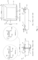
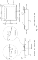
- first flexible seal system 10 used to create a substantially watertight seal between, in this instance, a first concrete panel 11 and a second concrete panel 12.
- first flexible seal member 13 proximate a first end of concrete panel 12.
- First flexible seal member 13 includes a surface component 24 extending over, and anchored into, a surface region 14 first concrete panel 11.
- the first flexible seal member 13 further includes at least an anchor component formed as legs or elongate flanges 15A,15B which, in this instance project substantially normal from and are cast into the surface region 14 of the first concrete panel 11, leaving the surface component 24 exposed above surface region 14.
- the first flexible seal member 13 further includes an overlap component 16 mechanically supported by and extending from the surface component 24 to extend past the end of the concrete panel 11.
- the first flexible seal member 13 thus described is shown in profile 1 of Figure 1 .
- the flexible seal system 10 further comprises a second flexible seal member 17, disposed proximate a second end of an abutting concrete panel 12, comprising, in this instance, a surface component 18 extending over a portion of the surface region 20.
- Second flexible seal member further includes an anchor component 19 in this instance in the form of a first leg 19 A and a second leg 19 B projecting preferably substantially at right angles from surface component 18,.
- the legs 19 A and 19 B are cast into the surface region 20 of second concrete panel 12 in such a way as to anchor surface component 18 reliably into the second concrete panel 12 whilst leaving surface component 18 exposed above surface region 20.
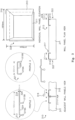
- the flexible seal members are arranged so that each concrete panel is provided with a first flexible seal member along each of a first pair of contiguous edges and with a second flexible seal member along each of a second pair of contiguous edges.
- first and second flexible seal members provides, in this embodiment, for sealing around both the vertical and horizontal edges of the panel.
- first flexible seal members 13 at their intersection 42 are mitrered and welded to form a watertight continuous seal surface.
- second flexible seal members 17 at their intersection 44 are mitrered and welded.
- junctions 46 between first and second flexible seal members are also mitrered and welded so that there is formed a continuous seal surface at the perimeter of the concrete panel.
- the cross sectioned view and enlargements of Figure 1C show the disposition of each of the first and second flexible seal members and their anchor portions relative the opposite edges of the concrete panel.
- the concrete panels of this preferred embodiment may be formed as follows.
- the flexible seal members are prepared in lengths to suit the dimensions of the panel to which they are to be applied and the ends mitrered as described above.
- the first and second flexible seal members are then welded at their intersections to form the continuous seal surface and positioned over formwork for the pouring of the concrete, with the anchor members suspended relative the formwork so as to become embedded within the concrete, and leaving the surface components extending over the surface.
- One the concrete has set, pressure testing of the flexible seal members completes the process.
- Each of the first and second flexible seal members comprises an integral polymer structure.
- first concrete panel 11 and the second concrete panel 12 are juxtaposed in sufficiently close relationship that overlap component 16 or at least a portion of it overlaps a longitudinal length of at least a portion of the surface component 18 as shown in the plan view of Figure 1 thereby to define a weld zone 21.
- the surface component extending along an outer surface of the concrete panel with the overlap portion disposed as shown in Figures 1 and 1A affords considerable flexibility to the seal of the invention, allowing some movement between two adjacent panels in at least two directions.
- the relatively short distance the anchor components of the two flexible seal members intrude into the concrete allows the flexible seal system of the invention to be used with relatively thin concrete panels. This may be contrasted for example with the arrangement of FR2415693 to Bachy discussed above, in which the arrangement of the flexible seal members require a much greater thickness of panel. It is noted also that the Bachy system creates an inherent weakness in the concrete by the long intrusion likely to lead to cracking.
- the overlap component 16 and surface component 18 are made from a weldable plastics material whereby, following the juxtaposition of the adjacent panels the overlap component 16 is welded along its length to the surface component 18 by means not shown.
- the overlap component of the first flexible seal member is of thinner or more pliable than the anchor components.
- Preferred materials for the flexible seal members 13, 17 include plastics materials, in particular, plastic materials which have the capacity to stretch and flex and preferably to be welded one to the other.
- Suitable materials include polymers; HDPE; PVC; Teflon and polymer blends. Preferably these materials may be particularly selected and optimized for properties such as elongation, resistance to chemicals, and resistance to heat. Polyethylene and polypropylene are particularly suited for petrochemical applications. PVC or PET may be suited to water applications.
- the same material is used for both the first flexible seal member 13 and the second flexible seal member 17 thereby to assist in homogeneity of the weld (see below).
- a preferred process of welding is thermal fusion welding utilising a modified plastics extruder machine (not shown) that can be hand operated and which extrudes a molten bead of High Elongation resin through a "stepped" die head over an overlapping weld zone 21.
- the weld zone 21 is prepared via abrasion prior to extrusion welding to remove surface grit and contamination.
- the weld consumable comprises the same material composition as that of the first flexible seal member 13 and second flexible seal member 17.
- FIG. 1A is a side section view of a preferred form of weld showing the consumable 40 enveloping a beveled edge portion of the overlap component 16 and at least a portion of the surface component 18.
- each weld is tested for water tightness at the completion of the weld.
- a plexiglass dome provided with a seal around its periphery, is placed over the area to be tested and a partial vacuum created under the dome to show up any imperfections. This testing is facilitated by the ready access available to the overlap component of the first flexible seal member and the bead of welding along the overlap edge.
- a preferred arrangement for the first concrete panel 11 is to have a flexible seal member of the first flexible seal member 13 aligned along a first edge 22 thereof and to have a second flexible seal member 17 aligned along an opposite parallel second edge 23 thereof as illustrated. Panels of like types and flexible seal member arrangements can then be juxtaposed side-by-side in the manner illustrated in the adjacent wall panels plan view of Figure 1 .
- a preferred distance between edges of adjacent panels is approximately 20 mm and with the opposed anchor component inset approximately 50 mm from an edge of an opposed panel edge with the overlap component extending approximately 130 mm from an edge of the panel into which it is anchored so as to thereby provide a weld zone of around 60 mm and where the face of the surface region of the second flexible seal member over which it extends is of the order of 90 mm in width.
- Typical precast concrete panel or cast in situ panel dimensions can be of the order of 1870 mm x 2170 mm or as required by the application.
- the panels themselves may be square, rectangular, cruciform, arched or other suitable shapes preferably adapted for adjacent abutting of long edges thereof.
- the flexible seal members are applied on the "inside" of the resulting barrier structure. That is to say on the side abutting the material or liquid which is being retained by the structure.
- first flexible seal member 213 includes a single anchor component 215 subtending from a surface component 24 which, in this instance, then extends integrally to the overlap component 216.
- FIG. 3 there is illustrated a third embodiment of a flexible seal system 310 where like components are numbered as for the first embodiment described with reference to Figure 1 except in the 300s series.
- the construction of the flexible seal members 313, 317 is substantially the same as that for the first embodiment.
- the second flexible seal member is placed as close to an edge of the concrete panel as possible rather than inset 50 mm as was the case with the arrangement of Figure 1 .
- the extension of the overlap component 316 may be reduced to 75 mm as a result.
- a wall structure 29 is comprised of lower juxtaposed panels 25, 26 joined at weld zone 30 above which are placed further panels 27, 28 which are themselves joined at weld zone 31.
- Upper panel 27 is joined at weld zone 32 to lower panel 25 whilst upper panel 28 is joined to lower panel 26 at weld zone 33 thereby to form a wall structure comprised of four concrete panels.
- Figure 4A illustrates the cross section a staged wall construction that may be applied with a vantage in some circumstances.
- the wall panel arrangement of Figure 4 or 4A can be used by way on non-limiting example of a dam wall, tunnel arch, tank farm vertical bund wall, sea wall.
- a fire-resistant/heat-resistant/chemical-resistant/UV-resistant expandable and/or flexible sealant or mastic may be inserted in the gap region between adjacent panels. In some forms this will be for the purpose of providing UV resistance. In other forms it will be for the purpose of providing heat resistance. In some forms this will be particularly for protecting the welded flexible seal.
- the above described system can be utilised as part of a methodology to reclaim landfill volume.
- An alternative arrangement which permits use of substantially the volume of the berm involves use of a substantially vertical wall structure 51 thereby permitting use of volume 52 that otherwise would be occupied by the berm itself.
- the vertical wall structure 51 is constructed utilising the arrangements described with reference to the earlier embodiments of Figures 1 to 4 .
- a preferred system which can be used as part of a landfill system includes:
- a liner may be applied to the filling area 60.
- a contiguous liner may be applied over the inside face of the wall structure 63, 65...
- the concrete panels with the flexible seal system of the invention are used for the sequential erection of a wall defining the boundary of refuse land fill.
- the concrete panels are erected with the flexible seal members on the rear surface of the panels, that is away from refuse land fill.
- the flexible seal member along the lower horizontal edge of the lowermost or first row of panels of the wall is the second flexible seal member described above and designated 17 in Figures 1 and 1A .
- a liquid proof seal between the wall and ground cover sheet of the land fill area can then be made by extending the polymer ground sheet of the land fill surface to lie under the foundation or toe of the wall to curve upward and, after the concrete panels are erected, welding the edge of the ground cover sheet to the flexible seal member of the panel.
- FIG. 7 there is illustrated a wall seal system 410, in accordance with an alternative example not covered by the appended claims, wherein like components are numbered as for earlier embodiments, except in the 400 series.
- the overlap component 416 comprises a separate component from the first flexible seal member 413 and the second flexible seal member 417. Accordingly, in use, the adjacent wall panels 411, 412 are juxtaposed and then the overlap component 416 is applied so as to overlap at least a portion of both the first flexible seal member 413 and the second flexible seal member 417, and substantially along the entire length thereof. The overlap component 416 is then welded to both flexible seal members 413, 417.
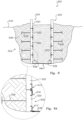
- the panels described above are arranged to form an irrigation channel 500 as shown in the cross section view of Figure 9 .
- many conventional irrigation channels 510 are formed in the manner shown in the cross section view of Figure 8 (prior art). These channels are formed by excavating a relatively shallow broad ditch 512 with the excavated material arranged in berms 514 on either side of the formed channel.
- the sides of the channel are no more than compacted earth which degrades the water carrying efficiency through seepage.
- the bottom and sides of the channel may be lined with concrete to prevent loss through seepage. In both cases however, the surface area 516 exposed to evaporation is large relative to the volume of water per unit length of the channel.
- each of the panels 520 may be provided with at least one conventional "tie back" 528 anchoring the panels to the back-filled, compacted soil areas 528 and 530.
- the proximate ends of the tie back elements 528 may be cast into the rear portions of the panels 520.
- the panels 520 may be provided on their rear sides with securing elements (not shown) cast into the concrete for attaching the tie back elements thereto.
- a number of panels 520 are arranged stacked one on top of another to a level at which the twin opposing vertical walls 524 and 526 extend above the level of the adjacent ground surface 534.
- the panels may be stacked in vertical alignment or may be staggered by a proportion of their length.
- the walls extend a metre above the surface, or to a level where access to the channel by wild and feral animals is prevented.
- the flexible seal members anchored in each of the panels are arranged so that a first flexible seal member of the type labelled 513 (13 in Figure 1 or 213 in Figure 2 ) is at the lower edge of the panel while the second flexible seal member of the type labelled respectively 518 (218 in Figures 1 and 2 ), is disposed at the upper edge.
- the overlap component of the first flexible seal member 513 overlaps the surface component of the second flexible seal member 518 along the surface of the wall.
- Panels 520 are further provided with complementary flexible seal members at their vertical edges and the panels positioned such that a flexible seal member 513 is adjacent to a flexible seal member 518.
- a flexible seal member 513 is adjacent to a flexible seal member 518.
- the vertical joints between longitudinally abutting panels may also be sealed by the welding of the overlapping portion of flexible seal members 513 to flexible seal members 518.
- first flexible seal members 518 of the lowermost panels 336 and 338 of each of the walls may be bent and laid against the surface of the bottom 340 of the channel as shown in Figure 9A .
- a liner 542 of a compatible impervious polymer material is then laid to overlap the flexible seal members and preferably welded to them in the same manner as already described to provide a watertight flexible seal between the twin opposing walls of the channel.
- the method of construction of irrigation channels by means of the panels of the invention provides a number of advantages over conventionally constructed channels. Firstly the panels are easily and rapidly erectable, especially, if in a preferred form, cast in low density concrete. Secondly the cast-in flexible seal members provide a simple and effective means of making the joints between abutting panels watertight. Furthermore the overlap components of the flexible seal members at the lower edges of the lowermost panel provide a unique element for the welded attachment of a liner for the bottom of the channel. Finally, the relatively narrow surface area to depth of the channel minimises water loss through evaporation.
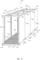
- precast concrete panels 610 provided with first and second flexible seal members as previously described, again form the opposing walls of the channel.
- the walls comprise of series of single vertical panels 610 extending the depth of the channel.
- Panels 610 are located in spacer elements 612 laid along the bottom of a prepared trench at intervals equal to the width of the panels 610.
- the lower edges 614 of the panels 610 are retained in grooves 616 formed in the ends of the spacer elements 612.
- Similar spacer elements 618 are located along the upper edges 620 of the panels 610 to form a controlled structure, with generally parallel vertical walls.
- Sealing along the vertical joints 608 between adjacent panels 610 is by means of the first and second configured flexible seal members described above, with the overlap component 622 of the first configured flexible seal member of one panel, welded to the surface portion of the second configured flexible seal member 624 of the adjacent panel.
- the panels 610 will be erected with the first and second flexible seal members directed to the inside of the irrigation channel as shown in Figure 10 , but in some applications the flexible seal members may be disposed on the outside of the panels.
- Panels 610 of this preferred arrangement are provided proximate their lower edges with a flexible seal member 626 of the form described above as the second configured flexible seal member. That is, a flexible seal member extending across the width of the panel 610 and comprising a surface component from which project at least two anchor components embedded into the concrete of the panel.
- the bottom of the channel 600 may be formed of a sheet 628 of polymer material compatible with that of the flexible seal members of the panels. These sheets forming the base of channel are formed or folded into a channel form with upturned flanges 630 which are then welded to the flexible seal members (not visible) along the lower edges of the panels. The sheets are of a length to overlap the width of the panels (as well as the spacer elements) so that the edge of an overlap of one sheet may be welded to the surface of the next adjacent sheet. Alternatively, the sheet 628 may be of sufficient length to extend past a number of panels 610 and spacer elements 612.
- the construction method illustrated in Figure 10 allows for a minimum of excavation and obviates the need for "tie back" of the panels into the adjacent soil body.
- the top of the channel 600 will usually remain open, it will be understood that the upper spacer elements 618 (or the upper edges 620 of the panels 610) may provide support for concrete cover slabs or other coverings, such as a security mesh for example.
- the panels 610 are provided proximate their upper edges 620 with first flexible seal members as described above.
- the channel may then be covered over with panels provided on their undersides with flexible seal members according to the invention to which the overlap components of the flexible seal members of the vertical panels may be welded.
- the channel in this arrangement may become a fully sealed conduit or tunnel for the movement of liquids under some pressure.
- the panels and the wall seal system of the invention may be applied to other liquid conveying channels such as storm water channels for example. It will further be appreciated that although the above described panels are planar, the flexible seal members of the invention may equally be applied to the edges of curved panels to form arched structures.
- the panels and the seal system of the invention may be adapted for the construction of a tunnel for the conveyance of cabling or traffic for example.
- the vertical and horizontal panels are arranged with the flexible seal members on the outward surfaces of the panels to make the joints between panels proof against external hydraulic pressure.
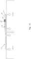
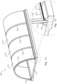
- the seal system may be applied to the seal of tunnels formed of curved panels to form arches as shown in Figure 11 .
- the tunnel 700 comprises a series of one-piece arched units 710 supported in a base slab 712, with the ends of the arched units 710 located in channels 714 cast into the base slab 712.
- Watertight flexible seal at the base of the arched units 710 of this arrangement of the tunnel 700 may include bedding the ends of the arched units 710 in a seal compound within the channels 714.
- sealing along the channels may be achieved by providing the outer ledge 716 of the channels with a flexible seal member of the second type as described above; that is a flexible seal member comprising a surface component 718 extending between two anchor components 720 as can be seen in the enlargement of Figure 12 .
- the surface components 720 provide for sealing with overlap components of first flexible seal members provided on the arched unit as explained below.
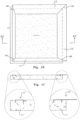
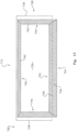
- the curved panels 710 for the tunnel 700 of Figure 11 are analogous to the panels for vertical walls described above and as illustrated in Figure 13 .
- a curved panel 710 and its flexible seal members are represented by a plane two-dimensional figure.
- the curved unit 710 is provided with flexible seal members 722 of the first type along one long side 724 (that is extending over the curve of the curved panel)
- the first flexible seal member comprises a surface component 730 extending over the surface 732 of the concrete from one, or preferably from between two anchor components, (not visible) embedded in the concrete of the curved panel, and an overlap component 734 extending beyond the perimeter 736 of the concrete curved panel.
- the two short sides 726 and 728 (that is the two base ends of the curved panel) are provided with wide flexible seal members of the second type, with the remaining opposite long side 738 (that is extending over the curve of the panel) also provided with a second flexible seal member 740.
- a second flexible seal member comprises a surface component 742 extending over the surface 732 of the concrete from at least one, preferably two, embedded anchor components (not visible) .
- the flexible seal members 722 and 740 form a continuous seal by mitering and welding at the intersecting comers.
- the overlap component 734 of a first flexible seal member projecting from the curved edge of a first curved panel overlaps the surface component along the curved edge of an adjoining curved panel and is heat welded to the surface component.
- the ends of the curved panels 710 may be sealed into the channel 714 of the base slab 712 by means of a sealing compound firstly placed in the channel.
- separate flashing strips 750 maybe welded both to the surface component of the flexible second seal members 742 at the ends of the curved panel, and to the surface component 718 of the flexible seal member provided along the outer ledges 716 of the channels 714 as explained above.
- the tunnel panels 710 are completely sealed panel to panel and to the base slab 712.
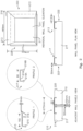
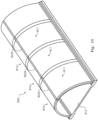
- a tunnel 800 as shown in Figure 15 is formed of curved panels made up of pairs of cooperating curved panels 810 and 811.
- the lower ends of the curved panels 810,811 are again located in a similar base slab 812 provided with channels as described above.
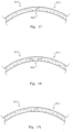
- the joint at the upper ends of the curved panels 810,811 may be arranged variously, for example as a stepped joint 802 or with a key block 804 as shown in the enlargements of Figures 16 and 17 .
- each arch unit comprises a pair of curved panels 810, 811
- the pairs are arranged with flexible seals as shown in Figure 16 .
- one long side of each panel is provided with a first flexible seal member 822 while the opposite long side is provided with a second flexible seal member.
- one of the pair of panels (say 811) is provide at its lower channel-seating end 806 with a second flexible seal member 840 but at its upper, jointing end, with a first flexible seal member 822A.
- the other panel of the pair (thus 810) is provided with flexible seal members in the same configuration as the panels of the single panel arches 710 and shown in Figure 13 .
- the method of sealing of the tunnel 800 is similar to that of the previously described tunnel 700 in every respect except that the sealing of the joint between the upper ends of a panel 810 and a panel 811 is now achieved by the overlap component of the first flexible seal member 822A of panel 811 being heat welded to the surface component of second flexible seal member 840A.
- the overlap component of flexible seal member 822A is simply increased in width to cover the joints at either side of the key block.
- the concept may be applied to either single piece arches, two piece arches or two piece and coupling-type arches.
- the system may be applied to bund walls for dams.
- the bund walls may be formed of vertical concrete panels as described above. Sealing between the panels is provided with the same first and second flexible seal members arranged at the edges of adjoining panels.
- the seal system of the invention may be applied in the construction of the walls of tanks in a tank farm.
- vertical panels are arranged to form either rectangular or circular enclosures with the vertical joints between abutting panels sealed by the first and second flexible seal members.
- the base of a tank so formed may comprise a sheet of compatible material which can be thermal fusion welded to the flexible seal members at the lower edges of the vertical panels to form a watertight tank enclosure.
Landscapes
- Engineering & Computer Science (AREA)
- Structural Engineering (AREA)
- Architecture (AREA)
- Civil Engineering (AREA)
- General Engineering & Computer Science (AREA)
- Electromagnetism (AREA)
- Physics & Mathematics (AREA)
- Mechanical Engineering (AREA)
- Mining & Mineral Resources (AREA)
- Manufacturing & Machinery (AREA)
- Ocean & Marine Engineering (AREA)
- Chemical & Material Sciences (AREA)
- Ceramic Engineering (AREA)
- Environmental & Geological Engineering (AREA)
- Life Sciences & Earth Sciences (AREA)
- General Life Sciences & Earth Sciences (AREA)
- Geochemistry & Mineralogy (AREA)
- Geology (AREA)
- Building Environments (AREA)
- Lining And Supports For Tunnels (AREA)
Claims (15)
- Ein flexibles Dichtungssystem (10) zur Bereitstellung einer im Wesentlichen wasserdichten Abdichtung zwischen benachbarten Betonplatten (11, 12); wobei das System umfasst:
ein erstes flexibles Dichtungselement (13), das in der Nähe eines ersten Endes (22) einer der genannten Betonplatten (11) anbringbar ist; wobei das erste flexible Dichtungselement (13) folgendes umfasst:mindestens ein Verankerungselement (15A);ein Oberflächenelement (24), das geeignet ist, einen Teil einer Außenfläche der genannten Betonplatte (11) zu überdecken; wobei sich das Oberflächenelement (24) von dem mindestens einen Verankerungselement (15A) erstreckt, das von dem Oberflächenelement (24) herausragt und geeignet ist, in die genannte Betonplatte (11) eingebettet zu werden;ein zweites flexibles Dichtungselement (17), das in der Nähe eines zweiten gegenüberliegenden Endes (23) einer angrenzenden genannten Betonplatte (12) anbringbar ist; wobei das zweite flexible Dichtungselement (17) folgendes umfasst:mindestens ein Verankerungselement (19A);ein Oberflächenelement (18), das geeignet ist, einen Teil einer Außenfläche (20) der genannten angrenzenden Betonplatte (12) zu überdecken; wobei sich das Oberflächenelement (18) des zweiten flexiblen Dichtungselements (17) von dem mindestens einen Verankerungselement (19A) erstreckt, das von dem Oberflächenelement (18) herausragt und geeignet ist, in die genannte angrenzende Betonplatte (12) eingebettet zu werden;dadurch gekennzeichnet, dass sich das Oberflächenelement (24) des ersten flexiblen Dichtungselements (13) integral zu einem Überlappungselement (16) erstreckt, wobei das Überlappungselement (16) geeignet ist, über das erste Ende (22) der genannten Betonplatte (11) hinauszureichen,wobei das Überlappungselement (16) des ersten flexiblen Dichtungselements (13) so strukturiert und ausgewählt ist, dass es in der Anwendung das Oberflächenelement (18) des zweiten flexiblen Dichtungselements (17) ausreichend überlappt, um das Verschweißen von mindestens einem Teil des Überlappungselements (16) des ersten flexiblen Dichtungselements (13) mit mindestens einem Teil des Oberflächenelements (18) des zweiten flexiblen Dichtungselements (17) zu ermöglichen, um eine durchgehende geschweißte Dichtung (21) zwischen und entlang der Länge des ersten flexiblen Dichtungselements (13) und des zweiten flexiblen Dichtungselements (17) zu bilden. - Das Dichtungssystem nach Anspruch 1, wobei die Länge des ersten flexiblen Dichtungselements und des zweiten flexiblen Dichtungselements eine Längslänge ist.
- Das Dichtungssystem nach Anspruch 1 oder 2, wobei das erste flexible Dichtungselement homogen ist.
- Das Dichtungssystem nach einem der Ansprüche 1 bis 3, wobei das zweite flexible Dichtungselement homogen ist.
- Das Dichtungssystem nach Anspruch 1, wobei das mindestens eine Verankerungselement (15A) des ersten flexiblen Dichtungselements (13) und das mindestens eine Verankerungselement (19A) des zweiten flexiblen Dichtungselements (17) in die jeweiligen ersten und zweiten gegenüberliegenden Enden (22, 23) der benachbarten Betonplatten (11, 12) eingegossen werden, indem das mindestens eine Verankerungselement (15A) des ersten flexiblen Dichtungselements und das mindestens eine Verankerungselement (19A) des zweiten flexiblen Dichtungselements in mindestens eine Oberflächenregion der benachbarten Betonplatten (11, 12) eingetaucht werden, bevor der Beton, aus dem die Platten geformt werden, aushärtet.
- Das Dichtungssystem nach Anspruch 5, wobei die von dem Oberflächenelement herausragenden Verankerungselemente jeweils einen knollenförmigen Abschnitt oder einen vergrößerten winkelförmigen Abschnitt an einer freien Kante des Verankerungselements aufweisen.
- Das Dichtungssystem nach einem der vorhergehenden Ansprüche, wobei das erste und das zweite flexible Dichtungselement ein Dichtungssystem bilden, das sich im Wesentlichen um den gesamten Umfang jeder Betonplatte erstreckt.
- Das Dichtungssystem nach einem der vorhergehenden Ansprüche, wobei das Verankerungselement eine im Wesentlichen durchgehende Verlängerung umfasst, die sich im Wesentlichen kontinuierlich längs über die gesamte Länge des flexiblen Dichtungselements erstreckt.
- Das Dichtungssystem nach einem der vorhergehenden Ansprüche, wobei das Verankerungselement eine im Wesentlichen unterbrochene, periodische Verlängerung umfasst, die sich im Wesentlichen längs über die gesamte Länge des flexiblen Dichtungselements erstreckt..
- Das Dichtungssystem nach einem der vorhergehenden Ansprüche, wobei die einzelnen Platten der genannten benachbarten Betonplatten (11, 12) eine oder mehrere der folgenden Formen aufweisen: quadratisch, rechteckig oder kreuzförmig.
- Das Dichtungssystem nach einem der vorhergehenden Ansprüche, wobei jede der Platten mit mindestens einer herkömmlichen Rückverankerung (528) versehen ist, die geeignet ist, die Platten an verfülltem, verdichtetem Boden (528, 530) zu verankern.
- Das Dichtungssystem nach einem der Ansprüche 1 bis 10, wobei die Platten der benachbarten Betonplatten (11, 12) vorgefertigt sind.
- Das Dichtungssystem nach einem der Ansprüche 1 bis 10, wobei die Platten der benachbarten Betonplatten (11, 12) vor Ort gegossen werden.
- Das Dichtungssystem nach einem der Ansprüche 1 bis 10, 12 oder 13, wobei die Platten der benachbarten Betonplatten (11, 12) geformt sind.
- Das Dichtungssystem nach einem der Ansprüche 1 bis 10, 12, 13 oder 14,
wobei die Platten der benachbarten Betonplatten (11, 12) gewölbt sind.
Applications Claiming Priority (3)
| Application Number | Priority Date | Filing Date | Title |
|---|---|---|---|
| AU2013206618A AU2013206618B1 (en) | 2013-06-28 | 2013-06-28 | Wall Seal System |
| AU2013263720A AU2013263720B2 (en) | 2013-06-28 | 2013-11-26 | Wall Seal System |
| PCT/AU2014/000667 WO2014205495A1 (en) | 2013-06-28 | 2014-06-27 | Wall seal system |
Publications (4)
| Publication Number | Publication Date |
|---|---|
| EP3014024A1 EP3014024A1 (de) | 2016-05-04 |
| EP3014024A4 EP3014024A4 (de) | 2017-03-29 |
| EP3014024C0 EP3014024C0 (de) | 2024-12-04 |
| EP3014024B1 true EP3014024B1 (de) | 2024-12-04 |
Family
ID=51684655
Family Applications (1)
| Application Number | Title | Priority Date | Filing Date |
|---|---|---|---|
| EP14816966.7A Active EP3014024B1 (de) | 2013-06-28 | 2014-06-27 | Wanddichtungssystem |
Country Status (4)
| Country | Link |
|---|---|
| US (2) | US9957711B2 (de) |
| EP (1) | EP3014024B1 (de) |
| AU (3) | AU2013206618B1 (de) |
| WO (1) | WO2014205495A1 (de) |
Families Citing this family (16)
| Publication number | Priority date | Publication date | Assignee | Title |
|---|---|---|---|---|
| SE541235C2 (en) * | 2016-07-11 | 2019-05-07 | Tekniska Verken I Linkoeping Ab | Method of providing a liquid proof joint between parts and structure comprising such joint |
| AU2016204976A1 (en) * | 2016-07-15 | 2018-02-01 | Mark Robert Edmund Curtis | Precast Concrete Panels used as Surface Lining of Perimeter Surfaces of Excavations |
| DE102016113770A1 (de) * | 2016-07-26 | 2018-02-01 | Tremco Illbruck Produktion Gmbh | Abdichtsystem für ein Wandungssystem |
| AU2016238840B2 (en) | 2016-10-04 | 2018-11-08 | Mark Robert Edmund Curtis | Bulwark Structure and Method |
| AU2018205148A1 (en) * | 2017-07-12 | 2019-01-31 | Nicholas William Myles Burnett | Expansion joint |
| US10240332B1 (en) * | 2018-01-23 | 2019-03-26 | Stetson Development, Inc. | Channel drain |
| CN108978595B (zh) * | 2018-09-11 | 2024-04-16 | 长江勘测规划设计研究有限责任公司 | 面板堆石坝周边缝底部止水修复结构及施工方法 |
| CN108952777A (zh) * | 2018-09-21 | 2018-12-07 | 中铁第四勘察设计院集团有限公司 | 一种盾构隧道新型复合式防水密封垫 |
| NL2023031B1 (en) * | 2019-04-30 | 2020-11-23 | Trelleborg Ridderkerk B V | Waterstop joint and method of installing a waterstop joint |
| CN111576461A (zh) * | 2020-06-08 | 2020-08-25 | 浙江乔兴建设集团有限公司 | 一种后浇带降排水结构及其施工方法 |
| CN113802842A (zh) * | 2020-06-17 | 2021-12-17 | 振中建设集团有限公司 | 一种装配式节点连接处无缝施工方法 |
| JP7592422B2 (ja) | 2020-07-30 | 2024-12-02 | 株式会社大林組 | 目地構造、及び、目地構造用部材の製造方法 |
| CN112720810A (zh) * | 2020-12-28 | 2021-04-30 | 南京珊秀科技有限公司 | 一种预应力混凝土管桩制作用浇筑成型系统 |
| DE102021102703A1 (de) * | 2021-02-05 | 2022-08-11 | Mageba Services & Technology Ag | Bauwerk |
| CN113005989A (zh) * | 2021-03-17 | 2021-06-22 | 上海市水利工程设计研究院有限公司 | 一种便于灵活组装的新型预制装配式临时防汛墙 |
| GB2601393C (en) * | 2021-06-10 | 2023-02-22 | Altro Ltd | Improvements in or relating to flooring |
Citations (2)
| Publication number | Priority date | Publication date | Assignee | Title |
|---|---|---|---|---|
| FR2526825A1 (fr) * | 1982-05-14 | 1983-11-18 | Soletanche | Element pour la realisation de panneaux de parois moulees dans le sol, parois comportant un tel element et procede pour la realisation d'une telle paroi |
| DE2557292C2 (de) * | 1975-12-19 | 1985-01-17 | Dynamit Nobel Ag, 5210 Troisdorf | Auskleidung von Betonrohren mittels flächiger Kunststoffdichtungselemente |
Family Cites Families (27)
| Publication number | Priority date | Publication date | Assignee | Title |
|---|---|---|---|---|
| US2816323A (en) * | 1953-04-22 | 1957-12-17 | Charles G Munger | Method of making plastic lined concrete pipe and joints therein |
| US2865267A (en) * | 1956-08-21 | 1958-12-23 | Alonzo W Bailey | Waterstop for expansion joints |
| US3112579A (en) * | 1959-08-20 | 1963-12-03 | Penetryn System | Flexible sealing system |
| US3114219A (en) * | 1961-04-24 | 1963-12-17 | Detroit Macoid Corp | Waterstop |
| US3145503A (en) * | 1961-06-27 | 1964-08-25 | Gordon L Brechin | Joint water stop |
| US3170268A (en) * | 1962-05-07 | 1965-02-23 | Balco Inc | Expansion joint cover structure |
| DE1509448C3 (de) * | 1964-09-18 | 1974-03-07 | Hannes 8022 Gruenwald Hartlmaier | Fertigbauteil |
| US3435574A (en) * | 1966-07-25 | 1969-04-01 | Edward C Hallock | Expansion joint covers |
| US3494092A (en) * | 1967-07-05 | 1970-02-10 | Delp W Johnson | Integrated folding slab construction |
| DE1759022A1 (de) * | 1968-03-21 | 1971-05-19 | Zueblin Ag | Beton-Tuebbing |
| DE1806902C3 (de) * | 1968-11-04 | 1978-03-23 | Ed. Zueblin Ag, 7000 Stuttgart | Fugendichtung für Beton-Tübbinge |
| US3696575A (en) * | 1971-06-07 | 1972-10-10 | Metalines Inc | Expansion joint cover |
| DE2542004A1 (de) * | 1975-09-20 | 1977-03-24 | Dynamit Nobel Ag | Fugenabdichtung zwischen aneinanderstossenden bauteilen aus mineralischen stoffen mittels eines fugenbandes aus thermoplastischem kunststoff |
| FR2415693A1 (fr) * | 1978-01-30 | 1979-08-24 | Sif Entreprise Bachy | Panneaux prefabriques comportant des elements d'etancheite pour la realisation de parois dans le sol et procedes les mettant en oeuvre |
| US4572702A (en) * | 1984-02-27 | 1986-02-25 | Bone John M | Expansion joint |
| DE3417294C2 (de) * | 1984-05-10 | 1987-02-12 | Köder, Kurt, 7443 Frickenhausen | Dehnfugenband zur Abdichtung von Fugen |
| DE3478130D1 (en) * | 1984-12-21 | 1989-06-15 | Miastoprojekt Sosnowiec | A method of joining and sealing elements in building structures and a connector for coupling elements of building structures |
| US4751799A (en) * | 1986-07-09 | 1988-06-21 | A-Lok Product, Inc. | Method and apparatus for lining manhole assemblies and the like |
| US4724649A (en) * | 1986-07-21 | 1988-02-16 | Lowndes Corporation | Side weld plate for concrete slabs |
| US4793162A (en) * | 1986-08-07 | 1988-12-27 | Spt, Inc. | Method for repairing failed waterstops and products relating to same |
| US4749307A (en) * | 1987-01-14 | 1988-06-07 | Baltimore Aircoil Company, Inc. | Seal structure for joint between two structural sections |
| DE3803060A1 (de) * | 1988-02-02 | 1989-08-03 | Kunz Alfred & Co | Dichtungsband |
| US4922676A (en) * | 1989-01-23 | 1990-05-08 | Spronken John R | Closure and seal for prefabricated building panels |
| US5168682A (en) * | 1990-10-05 | 1992-12-08 | Palle Rye | Plastic liners for concrete structural elements and the elements and structures produced thereby |
| DE20319304U1 (de) * | 2003-12-13 | 2004-04-01 | Gse Lining Technology Gmbh | Fugendichtungselement |
| ES2624313T3 (es) | 2011-10-19 | 2017-07-13 | Hans Voet | Artículo manufacturado hecho de material compuesto, para ser incorporado a una estructura de ingeniería civil |
| US20130160393A1 (en) * | 2011-12-22 | 2013-06-27 | Shildan, Inc. | Clip anchor connector |
-
2013
- 2013-06-28 AU AU2013206618A patent/AU2013206618B1/en active Active
- 2013-11-26 AU AU2013263720A patent/AU2013263720B2/en active Active
-
2014
- 2014-06-27 AU AU2014302022A patent/AU2014302022B2/en active Active
- 2014-06-27 EP EP14816966.7A patent/EP3014024B1/de active Active
- 2014-06-27 US US14/901,478 patent/US9957711B2/en active Active
- 2014-06-27 WO PCT/AU2014/000667 patent/WO2014205495A1/en not_active Ceased
-
2018
- 2018-03-27 US US15/936,864 patent/US10435883B2/en active Active
Patent Citations (2)
| Publication number | Priority date | Publication date | Assignee | Title |
|---|---|---|---|---|
| DE2557292C2 (de) * | 1975-12-19 | 1985-01-17 | Dynamit Nobel Ag, 5210 Troisdorf | Auskleidung von Betonrohren mittels flächiger Kunststoffdichtungselemente |
| FR2526825A1 (fr) * | 1982-05-14 | 1983-11-18 | Soletanche | Element pour la realisation de panneaux de parois moulees dans le sol, parois comportant un tel element et procede pour la realisation d'une telle paroi |
Also Published As
| Publication number | Publication date |
|---|---|
| AU2013263720A1 (en) | 2014-10-23 |
| EP3014024A4 (de) | 2017-03-29 |
| US9957711B2 (en) | 2018-05-01 |
| US10435883B2 (en) | 2019-10-08 |
| US20160122999A1 (en) | 2016-05-05 |
| EP3014024C0 (de) | 2024-12-04 |
| AU2014302022B2 (en) | 2017-12-14 |
| AU2013263720B2 (en) | 2016-02-25 |
| EP3014024A1 (de) | 2016-05-04 |
| AU2014302022A1 (en) | 2016-02-18 |
| AU2013206618B1 (en) | 2014-10-09 |
| US20180216341A1 (en) | 2018-08-02 |
| WO2014205495A1 (en) | 2014-12-31 |
Similar Documents
| Publication | Publication Date | Title |
|---|---|---|
| US10435883B2 (en) | Wall seal system | |
| AU2023203639B2 (en) | Precast Concrete Panels used as Surface Lining of Perimeter Surfaces of Excavations | |
| HRP20010434A2 (en) | Embankment dam and waterproofing method | |
| CZ279792B6 (cs) | Podzemní nepropustná stěna a způsob její výroby | |
| BR112012028470B1 (pt) | obra de engenharia civil, placa para forro e método para realizar uma obra de engenharia civil | |
| US10240310B2 (en) | Berm or levee expansion system and method | |
| JP4761780B2 (ja) | 遮水層の構築工法 | |
| JP4726147B2 (ja) | 遮水層の構築工法 | |
| JP7817356B2 (ja) | 浸出水集水ピット、廃棄物処分施設、及び浸出水集水ピットの構築方法 | |
| JP7564685B2 (ja) | 海面処分場護岸の遮水構造 | |
| JP4410572B2 (ja) | 埋立用護岸の構築方法 | |
| TR201807421T4 (tr) | Hidrolik bir yapının beton bordür taşlarına su geçirmezlik astarının kenetlenmesine yönelik yöntem ve sistem. | |
| JP5131742B2 (ja) | 護岸構造物の基礎構築工法 | |
| US9175454B2 (en) | Facing element for reinforced soil structure | |
| JP4749444B2 (ja) | 遮水層接続工法 | |
| JP2016087520A (ja) | 遮水構造 | |
| JP7478060B2 (ja) | 構造体間の接続部止水構造及び止水方法 | |
| JPH0438846B2 (de) | ||
| EP3270026A1 (de) | Verfahren zur bereitstellung einer flüssigkeitsdichten verbindung zwischen teilen und struktur mit einer derartigen verbindung | |
| SK9846Y1 (sk) | Spôsob odvodňovania základov stavieb osadených pod úrovňou terénu | |
| Vaschetti et al. | First underwater installation of a geomembrane system in a UK dam: Llyn Teifi spillway | |
| Tuna et al. | Rehabilitating The Artificial Ponds With Geosynthetic Clay Liners-A Case Study | |
| CS258351B1 (sk) | Tesniace podzemní stená zo samotvrdnúcej suspenzie a zvislých izolačných vrstiev a postup jej výroby |
Legal Events
| Date | Code | Title | Description |
|---|---|---|---|
| PUAI | Public reference made under article 153(3) epc to a published international application that has entered the european phase |
Free format text: ORIGINAL CODE: 0009012 |
|
| 17P | Request for examination filed |
Effective date: 20160127 |
|
| AK | Designated contracting states |
Kind code of ref document: A1 Designated state(s): AL AT BE BG CH CY CZ DE DK EE ES FI FR GB GR HR HU IE IS IT LI LT LU LV MC MK MT NL NO PL PT RO RS SE SI SK SM TR |
|
| AX | Request for extension of the european patent |
Extension state: BA ME |
|
| A4 | Supplementary search report drawn up and despatched |
Effective date: 20170223 |
|
| RIC1 | Information provided on ipc code assigned before grant |
Ipc: E02B 5/02 20060101ALI20170218BHEP Ipc: E04B 1/68 20060101ALI20170218BHEP Ipc: E02B 13/00 20060101ALN20170218BHEP Ipc: E21D 11/38 20060101ALI20170218BHEP Ipc: E04B 2/84 20060101ALN20170218BHEP Ipc: E02D 19/16 20060101ALI20170218BHEP Ipc: B28B 23/00 20060101ALI20170218BHEP Ipc: E02B 3/16 20060101AFI20170218BHEP |
|
| STAA | Information on the status of an ep patent application or granted ep patent |
Free format text: STATUS: EXAMINATION IS IN PROGRESS |
|
| 17Q | First examination report despatched |
Effective date: 20210518 |
|
| REG | Reference to a national code |
Ref country code: DE Ref legal event code: R079 Free format text: PREVIOUS MAIN CLASS: E02B0003160000 Ipc: B28B0023000000 Ref country code: DE Ref legal event code: R079 Ref document number: 602014091285 Country of ref document: DE Free format text: PREVIOUS MAIN CLASS: E02B0003160000 Ipc: B28B0023000000 |
|
| RIC1 | Information provided on ipc code assigned before grant |
Ipc: E02B 13/00 20060101ALN20231212BHEP Ipc: E21D 11/38 20060101ALI20231212BHEP Ipc: E02B 3/16 20060101ALI20231212BHEP Ipc: B28B 23/00 20060101AFI20231212BHEP |
|
| GRAP | Despatch of communication of intention to grant a patent |
Free format text: ORIGINAL CODE: EPIDOSNIGR1 |
|
| STAA | Information on the status of an ep patent application or granted ep patent |
Free format text: STATUS: GRANT OF PATENT IS INTENDED |
|
| RIC1 | Information provided on ipc code assigned before grant |
Ipc: E02B 13/00 20060101ALN20240117BHEP Ipc: E21D 11/38 20060101ALI20240117BHEP Ipc: E02B 3/16 20060101ALI20240117BHEP Ipc: B28B 23/00 20060101AFI20240117BHEP |
|
| INTG | Intention to grant announced |
Effective date: 20240129 |
|
| GRAJ | Information related to disapproval of communication of intention to grant by the applicant or resumption of examination proceedings by the epo deleted |
Free format text: ORIGINAL CODE: EPIDOSDIGR1 |
|
| STAA | Information on the status of an ep patent application or granted ep patent |
Free format text: STATUS: EXAMINATION IS IN PROGRESS |
|
| GRAP | Despatch of communication of intention to grant a patent |
Free format text: ORIGINAL CODE: EPIDOSNIGR1 |
|
| STAA | Information on the status of an ep patent application or granted ep patent |
Free format text: STATUS: GRANT OF PATENT IS INTENDED |
|
| INTC | Intention to grant announced (deleted) | ||
| RIC1 | Information provided on ipc code assigned before grant |
Ipc: E02B 13/00 20060101ALN20240604BHEP Ipc: E21D 11/38 20060101ALI20240604BHEP Ipc: E02B 3/16 20060101ALI20240604BHEP Ipc: B28B 23/00 20060101AFI20240604BHEP |
|
| INTG | Intention to grant announced |
Effective date: 20240624 |
|
| GRAS | Grant fee paid |
Free format text: ORIGINAL CODE: EPIDOSNIGR3 |
|
| GRAA | (expected) grant |
Free format text: ORIGINAL CODE: 0009210 |
|
| STAA | Information on the status of an ep patent application or granted ep patent |
Free format text: STATUS: THE PATENT HAS BEEN GRANTED |
|
| AK | Designated contracting states |
Kind code of ref document: B1 Designated state(s): AL AT BE BG CH CY CZ DE DK EE ES FI FR GB GR HR HU IE IS IT LI LT LU LV MC MK MT NL NO PL PT RO RS SE SI SK SM TR |
|
| REG | Reference to a national code |
Ref country code: GB Ref legal event code: FG4D |
|
| REG | Reference to a national code |
Ref country code: CH Ref legal event code: EP |
|
| REG | Reference to a national code |
Ref country code: DE Ref legal event code: R096 Ref document number: 602014091285 Country of ref document: DE |
|
| REG | Reference to a national code |
Ref country code: IE Ref legal event code: FG4D |
|
| U01 | Request for unitary effect filed |
Effective date: 20250102 |
|
| U07 | Unitary effect registered |
Designated state(s): AT BE BG DE DK EE FI FR IT LT LU LV MT NL PT RO SE SI Effective date: 20250218 |
|
| PG25 | Lapsed in a contracting state [announced via postgrant information from national office to epo] |
Ref country code: HR Free format text: LAPSE BECAUSE OF FAILURE TO SUBMIT A TRANSLATION OF THE DESCRIPTION OR TO PAY THE FEE WITHIN THE PRESCRIBED TIME-LIMIT Effective date: 20241204 |
|
| PG25 | Lapsed in a contracting state [announced via postgrant information from national office to epo] |
Ref country code: ES Free format text: LAPSE BECAUSE OF FAILURE TO SUBMIT A TRANSLATION OF THE DESCRIPTION OR TO PAY THE FEE WITHIN THE PRESCRIBED TIME-LIMIT Effective date: 20241204 |
|
| PG25 | Lapsed in a contracting state [announced via postgrant information from national office to epo] |
Ref country code: GR Free format text: LAPSE BECAUSE OF FAILURE TO SUBMIT A TRANSLATION OF THE DESCRIPTION OR TO PAY THE FEE WITHIN THE PRESCRIBED TIME-LIMIT Effective date: 20250305 |
|
| PG25 | Lapsed in a contracting state [announced via postgrant information from national office to epo] |
Ref country code: RS Free format text: LAPSE BECAUSE OF FAILURE TO SUBMIT A TRANSLATION OF THE DESCRIPTION OR TO PAY THE FEE WITHIN THE PRESCRIBED TIME-LIMIT Effective date: 20250304 |
|
| PG25 | Lapsed in a contracting state [announced via postgrant information from national office to epo] |
Ref country code: SM Free format text: LAPSE BECAUSE OF FAILURE TO SUBMIT A TRANSLATION OF THE DESCRIPTION OR TO PAY THE FEE WITHIN THE PRESCRIBED TIME-LIMIT Effective date: 20241204 |
|
| PG25 | Lapsed in a contracting state [announced via postgrant information from national office to epo] |
Ref country code: PL Free format text: LAPSE BECAUSE OF FAILURE TO SUBMIT A TRANSLATION OF THE DESCRIPTION OR TO PAY THE FEE WITHIN THE PRESCRIBED TIME-LIMIT Effective date: 20241204 |
|
| PGFP | Annual fee paid to national office [announced via postgrant information from national office to epo] |
Ref country code: GB Payment date: 20250626 Year of fee payment: 12 |
|
| PG25 | Lapsed in a contracting state [announced via postgrant information from national office to epo] |
Ref country code: IS Free format text: LAPSE BECAUSE OF FAILURE TO SUBMIT A TRANSLATION OF THE DESCRIPTION OR TO PAY THE FEE WITHIN THE PRESCRIBED TIME-LIMIT Effective date: 20250404 |
|
| PG25 | Lapsed in a contracting state [announced via postgrant information from national office to epo] |
Ref country code: SK Free format text: LAPSE BECAUSE OF FAILURE TO SUBMIT A TRANSLATION OF THE DESCRIPTION OR TO PAY THE FEE WITHIN THE PRESCRIBED TIME-LIMIT Effective date: 20241204 |
|
| PG25 | Lapsed in a contracting state [announced via postgrant information from national office to epo] |
Ref country code: CZ Free format text: LAPSE BECAUSE OF FAILURE TO SUBMIT A TRANSLATION OF THE DESCRIPTION OR TO PAY THE FEE WITHIN THE PRESCRIBED TIME-LIMIT Effective date: 20241204 |
|
| PLBE | No opposition filed within time limit |
Free format text: ORIGINAL CODE: 0009261 |
|
| STAA | Information on the status of an ep patent application or granted ep patent |
Free format text: STATUS: NO OPPOSITION FILED WITHIN TIME LIMIT |
|
| REG | Reference to a national code |
Ref country code: CH Ref legal event code: L10 Free format text: ST27 STATUS EVENT CODE: U-0-0-L10-L00 (AS PROVIDED BY THE NATIONAL OFFICE) Effective date: 20251015 |
|
| 26N | No opposition filed |
Effective date: 20250905 |
|
| REG | Reference to a national code |
Ref country code: CH Ref legal event code: U11 Free format text: ST27 STATUS EVENT CODE: U-0-0-U10-U11 (AS PROVIDED BY THE NATIONAL OFFICE) Effective date: 20251229 |
|
| PGFP | Annual fee paid to national office [announced via postgrant information from national office to epo] |
Ref country code: NO Payment date: 20251230 Year of fee payment: 12 |
|
| PGFP | Annual fee paid to national office [announced via postgrant information from national office to epo] |
Ref country code: CH Payment date: 20251229 Year of fee payment: 12 |
|
| PG25 | Lapsed in a contracting state [announced via postgrant information from national office to epo] |
Ref country code: MC Free format text: LAPSE BECAUSE OF FAILURE TO SUBMIT A TRANSLATION OF THE DESCRIPTION OR TO PAY THE FEE WITHIN THE PRESCRIBED TIME-LIMIT Effective date: 20241204 |
|
| U21 | Renewal fee for the european patent with unitary effect paid with additional fee |
Year of fee payment: 12 Effective date: 20251229 |
|
| PG25 | Lapsed in a contracting state [announced via postgrant information from national office to epo] |
Ref country code: IE Free format text: LAPSE BECAUSE OF NON-PAYMENT OF DUE FEES Effective date: 20250627 |