EP3014134B1 - Bague de tolérance à glissement de couple divisé - Google Patents
Bague de tolérance à glissement de couple divisé Download PDFInfo
- Publication number
- EP3014134B1 EP3014134B1 EP14736337.8A EP14736337A EP3014134B1 EP 3014134 B1 EP3014134 B1 EP 3014134B1 EP 14736337 A EP14736337 A EP 14736337A EP 3014134 B1 EP3014134 B1 EP 3014134B1
- Authority
- EP
- European Patent Office
- Prior art keywords
- tolerance ring
- rotational direction
- tolerance
- assembly
- outer component
- Prior art date
- Legal status (The legal status is an assumption and is not a legal conclusion. Google has not performed a legal analysis and makes no representation as to the accuracy of the status listed.)
- Active
Links
- 238000000034 method Methods 0.000 claims description 6
- 229910001220 stainless steel Inorganic materials 0.000 claims description 5
- 239000010935 stainless steel Substances 0.000 claims description 5
- 229910000639 Spring steel Inorganic materials 0.000 claims description 3
- 229910000975 Carbon steel Inorganic materials 0.000 claims description 2
- 229910000792 Monel Inorganic materials 0.000 claims description 2
- 230000004323 axial length Effects 0.000 claims description 2
- 229910052790 beryllium Inorganic materials 0.000 claims description 2
- 230000005540 biological transmission Effects 0.000 claims description 2
- 239000010962 carbon steel Substances 0.000 claims description 2
- 229910001026 inconel Inorganic materials 0.000 claims description 2
- 238000007373 indentation Methods 0.000 description 10
- 229910052751 metal Inorganic materials 0.000 description 5
- 239000002184 metal Substances 0.000 description 5
- 229910000831 Steel Inorganic materials 0.000 description 4
- 239000010959 steel Substances 0.000 description 4
- 230000015572 biosynthetic process Effects 0.000 description 3
- 238000005755 formation reaction Methods 0.000 description 3
- 239000000463 material Substances 0.000 description 3
- PXHVJJICTQNCMI-UHFFFAOYSA-N Nickel Chemical compound [Ni] PXHVJJICTQNCMI-UHFFFAOYSA-N 0.000 description 2
- 230000000712 assembly Effects 0.000 description 2
- 238000000429 assembly Methods 0.000 description 2
- 239000012858 resilient material Substances 0.000 description 2
- VYZAMTAEIAYCRO-UHFFFAOYSA-N Chromium Chemical compound [Cr] VYZAMTAEIAYCRO-UHFFFAOYSA-N 0.000 description 1
- CWYNVVGOOAEACU-UHFFFAOYSA-N Fe2+ Chemical compound [Fe+2] CWYNVVGOOAEACU-UHFFFAOYSA-N 0.000 description 1
- 229910000963 austenitic stainless steel Inorganic materials 0.000 description 1
- 238000005260 corrosion Methods 0.000 description 1
- 230000007797 corrosion Effects 0.000 description 1
- 230000001808 coupling effect Effects 0.000 description 1
- 230000033001 locomotion Effects 0.000 description 1
- 238000004519 manufacturing process Methods 0.000 description 1
- 230000013011 mating Effects 0.000 description 1
- 229910001092 metal group alloy Inorganic materials 0.000 description 1
- 238000012986 modification Methods 0.000 description 1
- 230000004048 modification Effects 0.000 description 1
- 229910052759 nickel Inorganic materials 0.000 description 1
- 230000002093 peripheral effect Effects 0.000 description 1
- 230000003068 static effect Effects 0.000 description 1
Images


Classifications
-
- F—MECHANICAL ENGINEERING; LIGHTING; HEATING; WEAPONS; BLASTING
- F16—ENGINEERING ELEMENTS AND UNITS; GENERAL MEASURES FOR PRODUCING AND MAINTAINING EFFECTIVE FUNCTIONING OF MACHINES OR INSTALLATIONS; THERMAL INSULATION IN GENERAL
- F16D—COUPLINGS FOR TRANSMITTING ROTATION; CLUTCHES; BRAKES
- F16D7/00—Slip couplings, e.g. slipping on overload, for absorbing shock
- F16D7/02—Slip couplings, e.g. slipping on overload, for absorbing shock of the friction type
- F16D7/021—Slip couplings, e.g. slipping on overload, for absorbing shock of the friction type with radially applied torque-limiting friction surfaces
-
- F—MECHANICAL ENGINEERING; LIGHTING; HEATING; WEAPONS; BLASTING
- F16—ENGINEERING ELEMENTS AND UNITS; GENERAL MEASURES FOR PRODUCING AND MAINTAINING EFFECTIVE FUNCTIONING OF MACHINES OR INSTALLATIONS; THERMAL INSULATION IN GENERAL
- F16D—COUPLINGS FOR TRANSMITTING ROTATION; CLUTCHES; BRAKES
- F16D1/00—Couplings for rigidly connecting two coaxial shafts or other movable machine elements
- F16D1/06—Couplings for rigidly connecting two coaxial shafts or other movable machine elements for attachment of a member on a shaft or on a shaft-end
- F16D1/08—Couplings for rigidly connecting two coaxial shafts or other movable machine elements for attachment of a member on a shaft or on a shaft-end with clamping hub; with hub and longitudinal key
- F16D1/0829—Couplings for rigidly connecting two coaxial shafts or other movable machine elements for attachment of a member on a shaft or on a shaft-end with clamping hub; with hub and longitudinal key with radial loading of both hub and shaft by an intermediate ring or sleeve
- F16D1/0835—Couplings for rigidly connecting two coaxial shafts or other movable machine elements for attachment of a member on a shaft or on a shaft-end with clamping hub; with hub and longitudinal key with radial loading of both hub and shaft by an intermediate ring or sleeve due to the elasticity of the ring or sleeve
Definitions
- the present disclosure is directed to tolerance rings, particularly to tolerance rings to provide a torque coupling effect between components.
- the present disclosure relates to tolerance rings and assemblies, wherein a tolerance ring provides an interference fit between components of an assembly.
- Tolerance rings may be used to provide an interference fit between parts required to transmit torque. Tolerance rings provide an efficient means of providing an interference fit between parts that may not be machined to exact dimensions. Tolerance rings have a number of other potential advantages, such as compensating for different linear coefficients of expansion between the parts, allowing rapid apparatus assembly, and durability.
- a tolerance ring generally comprises a strip of resilient material, for example a metal such as spring steel, the ends of which are brought together to form a ring.
- a band of protrusions extend radially outwards from the ring, and/or radially inwards towards the center of the ring.
- the protrusions are formations, possibly regular formations, such as corrugations, ridges or waves.
- EP 2 532 907 A2 describes a tolerance ring which is cylindrical about an axis and has a deformation region arranged with projections. The tolerance ring can have holes extending in the deformation region in longitudinal direction between peripheral regions.
- US 4,981,390 describes a tolerance ring with radial projections that can project radially inwardly or outwardly.
- each protrusion acts as a spring and exerts a radial force against the bearing and the surface of the bore, providing an interference fit between the bearing and the housing.
- a sliding shaft can be free to move axially through the bearing while the bearing remains securely installed within the housing.
- tolerance rings usually comprise a strip of resilient material that is curved to allow the easy formation of a ring by overlapping the ends of the strip, a tolerance ring may also be manufactured as an annular band.
- tolerance ring as used hereafter includes both types of tolerance ring.
- a tolerance ring is adapted to be deployed between inner and outer components.
- the tolerance ring includes a generally cylindrical body.
- the cylindrical body has a central axis.
- the cylindrical body can further include a sidewall that defines a first axial end and a second axial end.
- the sidewall can include an undeformed portion. Undeformed portions of the sidewall are regions free of protrusions, wave, extension, notches, openings, and other surface deformations. However, undeformed region allow for the portion to align with the curvature of the cylindrical body.
- the sidewall can further include a plurality of wave structures.
- the wave structures can protrude radially from the undeformed portion. Some or all wave structures can protrude inwardly, i.e. the apex of the wave structures is closer to the central axis than the undeformed portion. In another embodiment, some or all wave structures can protrude outwardly, i.e. the apex of the wave structures is farther to the central axis than the undeformed portion.
- the tolerance ring when placed in an assembly having an inner component and an outer component can have a first torque break-point T 1 in a first rotational direction.
- a torque break point for an assembly comprising an inner component, an outer component, and a tolerance ring is the torque at which slippage occurs.
- Torque slippage can be measured similar to or as described for steering devices in European Commission Directive for Automotives 95/56/EC (November 8, 1995).
- a torque break point can be determined with a test assembly comprising an inner component having a central axis, an outer component, wherein the outer component is held static, i.e. unrotatable about the central axis, and the inner component being rotatable around the central axis.
- a tolerance ring is placed between the inner and outer component and aligned to share the central axis with the inner component.
- Torque is applied to the inner component and the torque break point is defined as the necessary torque for slippage of the inner component to occur.
- the torque break point can be determined in a clockwise as well as a counter-clockwise rotation.
- the tolerance ring when placed in an assembly has a second torque break point T 2 in a second rotational direction opposite to the first rotational direction.
- an assembly can include an outer component.
- the outer component can include a bore.
- the assembly can further include an inner component disposed within the bore.
- the outer and inner component can share a common central axis.
- the assembly can further include a tolerance ring mounted between the inner component and the outer component.
- the tolerance ring includes a generally cylindrical body.
- the generally cylindrical body has a central axis, which aligns with the central axis of the inner and outer component.
- the tolerance ring can further include a sidewall that defines a first axial end and a second axial end.
- the sidewall can include an undeformed portion.
- the sidewall can further include a plurality of wave structures protruding radially from the undeformed portion.
- the wave structures can protrude radially inward or outward, or even alternate, i.e. some protrude inward and some outward.
- the assembly can have a first torque break-point T 1 between the inner component and the outer component in a first rotational direction.
- the assembly has further a second torque break point T 2 in a second rotational direction opposite to the first rotational direction.
- the ratio of T 1 /T 2 >1, i.e., the torsional moment needed for clockwise rotation is different than the torsional moment for counter-clockwise rotation.
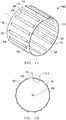
- the tolerance ring 100 can include a generally cylindrical body 102 having a generally cylindrical undeformed sidewall 104.
- the sidewall 104 can include a top 106 located at a first axial end and a bottom 108 located at a second axial end, opposite to the first axial end.
- the sidewall 104 can include a first end 110 and a second end 112.
- a gap 114 can be established between the first end 110 and the second end 112 of the sidewall 104.
- the gap 114 can extend completely through the sidewall 104 in order to form a split in the sidewall 104 of the tolerance ring 100.
- the tolerance ring 100 can include a center axis 116.
- the sidewall 104 of the tolerance ring 100 can include an upper undeformed band 120 near, or adjacent to, the top 106 of the sidewall 104.
- the sidewall 104 can also include a lower undeformed band 122 near, or adjacent to, the bottom 108 of the sidewall 104 opposite the upper unformed band 120.
- Undeformed sections 124 can extend axially along the length of the sidewall 104 between, and extending from, the undeformed bands 120 and 122.
- the tolerance ring 100 can include a plurality of wave structures 130 formed in the sidewall 104.
- the wave structures 130 can protrude radially outward, or inward (not shown), from the sidewall 104 away from, or toward, the central axis 116 of the tolerance ring 100.
- Each wave structure 130 is connected only to the undeformed sections 124 such that the portion near the undeformed bands 120 and 122 of wave structures 130 are open.
- the wave structure 130 is connected to the undeformed sections 124 and the undeformed bands 120 and 122.
- each undeformed section 124 is located between adjacent wave structures 130 and each wave structure 130 is located between adjacent unformed sections 124 so the wave structures 130 and unformed sections 124 alternate around a circumference of the sidewall 104.
- the tolerance ring 100 can include one row, or band, of wave structures.
- the tolerance ring can include two rows, or bands, of wave structures; three rows, or bands, of wave structures; etc.
- a total number of wave structures, N WS in each row can be ⁇ 3, such as ⁇ 4, ⁇ 5, ⁇ 6, ⁇ 7, ⁇ 8, or ⁇ 9.
- N WS ⁇ 30, ⁇ 25, ⁇ 20, or ⁇ 15.
- N WS can be within a range between and including any of the N WS values above. In a particular embodiment, as shown in FIGs. 1A and 1B , N WS can be 15.
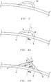
- the wave structure 130 has an asymmetric profile. As shown in FIG. 3A , the wave structure 130 spans over an undeformed section
- includes a midpoint M AB .
- portion p 1 has a midpoint MP 1 located halfway between
- FIG. 3B discloses the tangential slope of s 1 of portion p 1 and touching MP 1 .
- the slope s 1 can be determined by the angle ⁇ between s 1 and r c .
- tan( ⁇ -90°).
- portion p 2 has a tangential slope s 2 at midpoint MP 2 which cuts r c at an angle ⁇ . Accordingly, the absolute slope value
- tan( ⁇ -90°).
- is different from
- is greater than 1, such as greater than 1.1, greater than 1.2, greater than 1.4, greater than 1.8, greater than 2.0, greater than 2.5, greater than 3.0, greater than 4.0, greater than 5.0, or greater than 10.
- is less than 10.5, such as less than 5.5, less than 4.5, less than 3.5, less than 2.8, less than 2.3, less than 2.1, less than 1.9, less than 1.7, less than 1.5, or less than 1.3.
- can range from 1.1 to 3.5, such as from 1.4 to 3.0.
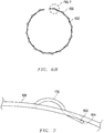
- FIGs. 4A and 4B an exemplary tolerance ring is illustrated includes the same elements as shown in FIGs 1A through 3B , with one exception.
- extensions 402 are located between wave structures 130.
- the extensions 402 protrude radially in a direction opposite to the direction of adjacent wave structures.
- the wave structures 130 can be separated from extensions 402 by undeformed regions 424.
- the extensions 402 can have a terminating edge 404.
- Edge 404 can be disconnected from the undeformed portion 424.
- edge 404 can be connected to portion 424.
- the extensions are not separated from an adjacent wave structure 130 by an undeformed region as shown in FIG. 6 .
- the extensions 602 are connected to an adjacent wave structure 130.
- the extensions 602 can include a terminating edge 604, which can be disconnected from the undeformed portion 624.
- the terminating edge can remain connected from the undeformed sidewall portion 624.
- the tolerance ring 100 can be utilized in an assembly that includes an outer component that has a bore formed within the outer component and an inner component disposed within the bore.
- the outer component can be a housing formed with a bore and the inner component can be a rack shaft bearing. Further, the tolerance ring 100 can be mounted between the inner component and the outer component.
- the inner component can have a surface structure that engages with the extensions 402 or 602.
- such surface structure can be congruent with the inner surface of the tolerance ring when assembled.
- the inner component can have grooves, notches, or indentations.
- the indentations can have a V-shaped cross-section.
- the cross-section of the inner component can have U-shaped indentations, L-shaped indentations, J-shaped indentations, or any combination thereof.
- a tolerance ring 100 described herein can be made from a metal, a metal alloy, or a combination thereof.
- the metal can include a ferrous metal.
- the metal can include steel.
- the steel can include stainless steel, such as austenitic stainless steel.
- the steel can include stainless steel comprising chrome, nickel, or a combination thereof.
- the steel can X10CrNi18-8 1.4310 stainless steel.
- the tolerance ring can include a Vickers pyramid number hardness, VPN, which can be ⁇ 350, such as ⁇ 375, ⁇ 400, ⁇ 425, or ⁇ 450. VPN can also be ⁇ 600, ⁇ 500, ⁇ 475, or ⁇ 450.
- the tolerance ring can be treated to increase its corrosion resistance.
- the tolerance ring can be passivated.
- the tolerance ring can be passivated according to the ASTM standard A967.
- the inner component is made of a material having a VPN IC less than the tolerance ring VPN TR , i.e. VPN IC ⁇ VPN TR .
- the tolerance ring is of a harder material than the inner component.
- the stock material from which the tolerance ring 100 can be formed can have a thickness, T, and T can be ⁇ 0.1 mm, such as ⁇ 0.2 mm, > 0.3 mm, > 0.4 mm, > 0.5 mm, or ⁇ 0.6 mm.
- T can be ⁇ 1.0 mm, ⁇ 0.9 mm, or ⁇ 0.8 mm.
- T can be within a range between, and including, any of the values of T disclosed above.
- the tolerance ring 100 may have an overall outer diameter, OD, and OD can be ⁇ 37.5 mm, such as ⁇ 40 mm, ⁇ 45 mm, ⁇ 50 mm, ⁇ 55 mm, or ⁇ 60 mm.
- the OD can be ⁇ 37.5 mm, such as ⁇ 35 mm, or ⁇ 30 mm. Further, OD can be within a range between and including any of the values of OD described herein.
- the tolerance ring can have an overall length, L, and L can be ⁇ 233 mm, ⁇ 235 mm, > 240 mm, > 250 mm, or ⁇ 260 mm.
- L can be ⁇ 233 mm, such as ⁇ 230 mm, ⁇ 225 mm, ⁇ 220 mm, or ⁇ 210 mm.
- L can be within a range between, and including, any of the values of L described above.
- a tolerance ring adapted to be deployed between inner and outer components.
- the tolerance ring comprises a generally cylindrical body having a central axis and a sidewall that defines a first axial end and a second axial end.
- the sidewall includes an undeformed portion, and a plurality of wave structures protruding radially from the undeformed portion.
- Each wave structure is located between, and connected to, undeformed sections.
- At least one wave structure has asymmetric cross-section profile.
- the tolerance ring is adapted to have a first torque break-point T 1 in a first rotational direction and a second torque break point T 2 in a second rotational direction opposite to the first rotational direction, wherein a ratio of T 1 /T 2 >1.
- the tolerance ring may further comprise a gap extending along the entire axial length of the body, wherein the gap establishes a split in the body.
- each wave structure may have an asymmetric cross-section as viewed in a plane perpendicular to the central axis.
- a radial line bisecting the asymmetric cross-section may divide the cross-section into a first arc and a second arc.
- the first arc may have an absolute value of a first tangential slope s 1 at a mid-point MP 1 and the second arc may have an absolute value of a second tangential slope s 2 at a mid-point MP 2 , and
- may be greater than 1, such as greater than 1.1, greater than 1.2, greater than 1.4, greater than 1.8, greater than 2.0, greater than 2.5, or greater than 3.0, but not greater than 20.
- each wave structure may protrude in a first radial direction
- the tolerance ring may further comprise a plurality of extensions, each extension protruding in a second radial direction opposite to the first radial direction.
- each extension may further include a terminating edge, the terminating edge disconnected from the side wall.
- the terminating edge may be adapted to frictionally engage the inner or the outer component so as to provide an increase of T 1 /T 2 .
- the increase of T 1 /T 2 may be at least 0.05, such as at least 0.1, at least 0.2, at least 0.5, at least 0.7, at least 1, at least 2, at least 10, at least 20, at least 30, or at least 50, but not greater than 1000.
- Each extension may extend from a lateral side of a respective wave structure, wherein the extension and the lateral side of respective wave structures are disconnected from the sidewall.
- the inner or outer component may further include a structured surface adapted to receive the extensions.
- a cross-section of the structured surface of the inner or the outer component as viewed in a plane perpendicular to the central axis may include V-shaped indentations, U-shaped indentations, L-shaped indentations, J-shaped indentations, or any combination thereof.
- the ratio of T 1 /T 2 may be greater than 1.05, such as greater than 1.1, greater than 1.2, greater than 1.5, greater than 2, greater than 5, greater than 10, greater than 15, greater than 20, greater than 30, greater than 50, greater than 70, greater than 100, but not greater than 1000.
- the tolerance ring may comprise carbon steel, stainless steel, spring steel, inconel, monel, incalloy, phynox, or copper-beryllium.
- the tolerance ring may have a Vickers hardness HV of at least 50, such as at least 55, at least 60, at least 65, at least 70, at least 75, at least 80, at least 85, at least 90, at least 95, at least 100, at least 110, at least 115, at least 120, at least 125, at least 130, at least 135, at least 140, at least 145, at least 150, at least 160, at least 170, at least 180, at least 190, or at least 200.
- the tolerance ring may have a Vickers hardness HV of not greater than 600, such as not greater than 550, not greater than 500, not greater than 450, not greater than 400, not greater than 350, not greater than 300, or not greater than 250.
- an assembly comprising an outer component including a bore, an inner component disposed within the bore, and a tolerance ring as described herein mounted between the inner component and the outer component.
- the tolerance ring may have a Vickers hardness HV TR and the inner component may have a Vickers hardness HVic, wherein HV TR / HV IC > 1.
- HV TR / HV IC may be greater than 1.05, such as greater than 1.1, greater than 1.2, greater than 1.3, greater than 1.4, greater than 1.5, greater than 1.6, greater than 1.7, greater than 1.8, greater than 1.9, greater than 2.0, greater than 2.5, or greater than 3, but not greater than 30.
- the tolerance ring may have a Vickers hardness HV TR and the outer component may have a Vickers hardness HV OC , wherein HV TR / HV OC > 1.
- HV TR / HV OC may be greater than 1.05, such as greater than 1.1, greater than 1.2, greater than 1.3, greater than 1.4, greater than 1.5, greater than 1.6, greater than 1.7, greater than 1.8, greater than 1.9, greater than 2.0, greater than 2.5, or greater than 3, but not greater than 30.
- a method of dividing torque transmission comprises providing an assembly as described herein.
- the method further comprises applying torque about the central axis to the inner or the outer component in a first rotational direction, wherein the torque break point in the first rotational direction T 1 is different from a torque break point T 2 in a second rotational direction opposite to the first rotational direction.
Landscapes
- Engineering & Computer Science (AREA)
- General Engineering & Computer Science (AREA)
- Mechanical Engineering (AREA)
- Springs (AREA)
- Snaps, Bayonet Connections, Set Pins, And Snap Rings (AREA)
- Rolling Contact Bearings (AREA)
Claims (15)
- Bague de tolérance (100) adaptée pour être déployée entre des composants interne et externe, comprenant : un corps généralement cylindrique (102) ayant un axe central (116) et une paroi latérale (104) qui définit une première extrémité axiale et une seconde extrémité axiale,
dans laquelle la paroi latérale comprend :une partie non déformée (120, 122, 124) ; etune pluralité de structures d'ondes (130) faisant saillie radialement depuis la partie non déformée, caractérisée en ce que chaque structure d'ondes est située entre, et reliée à, des sections non déformées (124), dans laquelle au moins une structure d'ondes a un profil de section transversale asymétrique,dans laquelle la bague de tolérance est adaptée pour avoir un premier point de rupture de couple T1 dans un premier sens de rotation et un second point de rupture de couple T2 dans un second sens de rotation opposé au premier sens de rotation, dans laquelle un rapport T1/T2 > 1. - Bague de tolérance selon la revendication 1, comprenant en outre un espace (114) s'étendant sur toute la longueur axiale du corps, l'espace établissant une scission dans le corps.
- Bague de tolérance selon l'une quelconque des revendications précédentes, dans laquelle chaque structure d'ondes a une section transversale asymétrique telle que vue dans un plan perpendiculaire à l'axe central.
- Bague de tolérance selon la revendication 3, dans laquelle une ligne radiale coupant en deux la section transversale asymétrique divise la section transversale en un premier arc et un second arc.
- Bague de tolérance selon la revendication 4, dans laquelle le premier arc a une valeur absolue d'une première pente tangentielle s1 en un point médian MP1 et le second arc a une valeur absolue d'une seconde pente tangentielle s2 en un point médian MP2, et |s1| ≠ |s2|.
- Bague de tolérance selon l'une quelconque des revendications précédentes, dans laquelle chaque structure d'ondes fait saillie dans une première direction radiale, la bague de tolérance comprenant en outre une pluralité d'extensions (402, 602), chaque extension faisant saillie dans une seconde direction radiale opposée à la première direction radiale.
- Bague de tolérance selon la revendication 6, dans laquelle l'extension comprend en outre un bord de terminaison (404, 604), le bord de terminaison étant déconnecté de la paroi latérale.
- Bague de tolérance selon la revendication 7, dans laquelle le bord de terminaison est adapté pour venir en prise par friction avec le composant interne ou externe de manière à fournir une augmentation de T1/T2.
- Bague de tolérance selon la revendication 6, dans laquelle chaque extension s'étend à partir d'un côté latéral d'une structure d'ondes respective, dans laquelle l'extension et le côté latéral des structures d'ondes respectives sont déconnectés de la paroi latérale.
- Bague de tolérance selon l'une quelconque des revendications précédentes, dans laquelle la bague de tolérance comprend de l'acier au carbone, de l'acier inoxydable, de l'acier à ressort, de l'inconel, du monel, de l'incalloy, du phynox ou du cuivre-béryllium.
- Assemblage comprenant :un composant externe comprenant un alésage ;un composant interne disposé à l'intérieur de l'alésage ; etla bague de tolérance selon l'une quelconque des revendications précédentes, la bague de tolérance étant montée entre le composant interne et le composant externe.
- Assemblage selon la revendication 11, dans lequel le composant interne ou externe comprend en outre une surface structurée adaptée pour recevoir des extensions de la bague de tolérance.
- Assemblage selon l'une quelconque des revendications 11 à 12, dans lequel la bague de tolérance a une dureté Vickers HVTR et le composant interne a une dureté Vickers HVIC, dans lequel HVTR/HVIC > 1.
- Assemblage selon l'une quelconque des revendications 11 à 13, dans lequel la bague de tolérance a une dureté Vickers HVTR et le composant externe a une dureté Vickers HVoc, dans lequel HVTR/HVOC > 1.
- Procédé de division de la transmission de couple, le procédé comprenant
fournir l'assemblage selon l'une quelconque des revendications 11 à 14 ; et
appliquer un couple autour de l'axe central au composant interne ou externe de l'assemblage dans un premier sens de rotation, le point de rupture du couple dans le premier sens de rotation T1 étant différent d'un point de rupture du couple T2 dans un second sens de rotation opposé au premier sens de rotation.
Priority Applications (1)
| Application Number | Priority Date | Filing Date | Title |
|---|---|---|---|
| PL14736337T PL3014134T3 (pl) | 2013-06-27 | 2014-06-27 | Pierścień tolerancyjny dzielonym momentem obrotowym z poślizgiem |
Applications Claiming Priority (2)
| Application Number | Priority Date | Filing Date | Title |
|---|---|---|---|
| US201361840451P | 2013-06-27 | 2013-06-27 | |
| PCT/EP2014/063737 WO2014207219A1 (fr) | 2013-06-27 | 2014-06-27 | Bague de tolérance à glissement de couple divisé |
Publications (2)
| Publication Number | Publication Date |
|---|---|
| EP3014134A1 EP3014134A1 (fr) | 2016-05-04 |
| EP3014134B1 true EP3014134B1 (fr) | 2019-10-09 |
Family
ID=51136445
Family Applications (1)
| Application Number | Title | Priority Date | Filing Date |
|---|---|---|---|
| EP14736337.8A Active EP3014134B1 (fr) | 2013-06-27 | 2014-06-27 | Bague de tolérance à glissement de couple divisé |
Country Status (7)
| Country | Link |
|---|---|
| US (1) | US10094426B2 (fr) |
| EP (1) | EP3014134B1 (fr) |
| JP (1) | JP6223562B2 (fr) |
| KR (1) | KR101920619B1 (fr) |
| CN (1) | CN105339691B (fr) |
| PL (1) | PL3014134T3 (fr) |
| WO (1) | WO2014207219A1 (fr) |
Families Citing this family (14)
| Publication number | Priority date | Publication date | Assignee | Title |
|---|---|---|---|---|
| CA2916006C (fr) | 2013-06-29 | 2018-01-16 | Saint-Gobain Performance Plastics Corporation | Support a utiliser dans un appui-tete coulissant |
| US9908167B1 (en) * | 2015-03-02 | 2018-03-06 | Western Digital Technologies, Inc. | Disk drive tolerance ring with edge rounding from opposite major faces |
| JP6372455B2 (ja) * | 2015-09-07 | 2018-08-15 | トヨタ自動車株式会社 | 車両用動力伝達装置 |
| JP6380361B2 (ja) * | 2015-12-10 | 2018-08-29 | トヨタ自動車株式会社 | 車両の動力伝達装置 |
| JP6468176B2 (ja) * | 2015-12-10 | 2019-02-13 | トヨタ自動車株式会社 | 車両の動力伝達装置 |
| JP6341216B2 (ja) * | 2016-02-09 | 2018-06-13 | トヨタ自動車株式会社 | 車両の動力伝達装置 |
| WO2018083021A1 (fr) * | 2016-11-01 | 2018-05-11 | Saint-Gobain Performance Plastics Rencol Limited | Frein à friction |
| ES2983698T3 (es) * | 2017-03-31 | 2024-10-24 | Saint Gobain Performance Plastics Pampus Gmbh | Ensamblaje con anillo para control de desplazamiento de componentes |
| PL3688330T3 (pl) | 2017-09-29 | 2026-04-20 | Saint-Gobain Performance Plastics Rencol Limited | Pierścień tolerancyjny |
| DE102018215514A1 (de) * | 2018-09-12 | 2020-03-12 | Robert Bosch Gmbh | Ausgleichselement |
| KR102765344B1 (ko) | 2020-01-16 | 2025-02-13 | 생-고뱅 퍼포먼스 플라스틱스 렌콜 리미티드 | 조향 조립용 베어링 |
| TWI874880B (zh) * | 2021-12-30 | 2025-03-01 | 德商聖高拜塑膠製品股份有限公司 | 滑動組件、總成、及其形成與使用方法 |
| USD1065994S1 (en) * | 2022-07-29 | 2025-03-11 | Kennametal Inc. | Tool retainer |
| US11898446B1 (en) | 2022-07-29 | 2024-02-13 | Kennametal Inc. | Tool retainer |
Family Cites Families (28)
| Publication number | Priority date | Publication date | Assignee | Title |
|---|---|---|---|---|
| US3142887A (en) * | 1960-09-14 | 1964-08-04 | Star Kugelhalter Gmbh Dt | Method of making a split annular tolerance ring |
| FR1407704A (fr) | 1964-06-17 | 1965-08-06 | Peugeot Et Cie Sa | Bande destinée à donner des éléments de solidarisation en rotation entre deux pièces concentriques, éléments obtenus à partir de cette bande et assemblages réalisés |
| IT984360B (it) | 1972-03-06 | 1974-11-20 | Star Kugelhalter Gmbh Dt | Elemento di inserto interponibile tra organi di macchine a scopo di collegamento |
| US3854561A (en) | 1973-05-09 | 1974-12-17 | Department Of Health Education | Unidirectional slip clutch |
| JPS6039541Y2 (ja) | 1977-10-26 | 1985-11-27 | エヌ・テ−・エヌ東洋ベアリング株式会社 | 一方向クラツチ |
| US4286894A (en) * | 1979-03-21 | 1981-09-01 | Roller Bearing Company Of America | Tolerance rings |
| US4981390A (en) | 1987-03-06 | 1991-01-01 | The Ray Engineering Co., Ltd. | Tolerance ring with retaining means |
| JPH0610230Y2 (ja) * | 1988-11-17 | 1994-03-16 | エヌティエヌ株式会社 | 一方向クラッチ付き回転体 |
| US5595272A (en) | 1995-04-25 | 1997-01-21 | The Timken Company | Unidirectional clutch |
| GB2327717B (en) | 1997-03-03 | 2001-02-14 | Luk Fahrzeug Hydraulik | Compressor for the air-conditioning system of a motor vehicle |
| DE10085247T1 (de) * | 1999-12-03 | 2002-11-07 | Seagate Technology Llc | Toleranzring mit konsistentem niedrigem Einbaukraftprofil |
| JP3536022B2 (ja) | 2000-10-04 | 2004-06-07 | ミネベア株式会社 | ピボット軸受装置 |
| US6994587B2 (en) * | 2003-07-23 | 2006-02-07 | Andrew Corporation | Coaxial cable connector installable with common tools |
| JP2005114025A (ja) | 2003-10-07 | 2005-04-28 | Ochiai:Kk | トレランスリング |
| US20050225903A1 (en) * | 2004-04-02 | 2005-10-13 | Sprankle Matthew S | Tolerance ring with debris-reducing profile |
| JP2006038039A (ja) | 2004-07-23 | 2006-02-09 | Ntn Corp | トルクリミッタ |
| JP4377397B2 (ja) | 2006-07-31 | 2009-12-02 | 政夫 浅野 | 過負荷トルク遮断装置 |
| GB0615672D0 (en) * | 2006-08-07 | 2006-09-13 | Rencol Tolerance Rings Ltd | Assembly of a shaft and a housing assembly |
| US7580225B2 (en) * | 2006-08-15 | 2009-08-25 | Intri-Plex Technologies, Inc. | Tolerance ring having variable height and/or assymmetrically located bumps |
| US7850389B2 (en) * | 2006-08-15 | 2010-12-14 | Intriplex Technologies, Inc. | Tolerance ring having various end tab designs to prevent interlocking |
| PL1898108T3 (pl) * | 2006-09-07 | 2012-12-31 | Saint Gobain Performance Plastics Rencol Ltd | Kombinowany pierścień montażowy |
| US7554771B2 (en) * | 2006-09-11 | 2009-06-30 | Intri-Plex Technologies, Inc. | Tolerance ring for data storage with overlapping tab feature for mass control |
| EP1961979B1 (fr) * | 2007-02-20 | 2013-07-03 | Saint-Gobain Performance Plastics Rencol Limited | Ensemble de montage |
| EP1985875B1 (fr) * | 2007-04-24 | 2013-10-02 | Saint-Gobain Performance Plastics Rencol Limited | Ensemble de montage |
| WO2012144628A1 (fr) * | 2011-04-22 | 2012-10-26 | 日本発條株式会社 | Bague tolérancée et procédé de fabrication d'une bague tolérancée |
| DE102011077361A1 (de) | 2011-06-10 | 2012-12-13 | FedertechnikKaltbrunn AG | Feder für eine Welle-/ Nabeverbindung mit Überlastschutzfunktion, insbesondere für Heckklappenantriebe |
| JP5849825B2 (ja) * | 2012-03-29 | 2016-02-03 | 日本精工株式会社 | 磁気記憶装置のスイングアーム用ピボット軸受け装置およびこれを用いた磁気記録装置 |
| WO2014114679A1 (fr) * | 2013-01-23 | 2014-07-31 | Saint-Gobain Performance Plastics Rencol Limited | Bague de tolérance de limitation de couple |
-
2014
- 2014-06-25 US US14/314,997 patent/US10094426B2/en active Active
- 2014-06-27 WO PCT/EP2014/063737 patent/WO2014207219A1/fr not_active Ceased
- 2014-06-27 JP JP2016522541A patent/JP6223562B2/ja not_active Expired - Fee Related
- 2014-06-27 PL PL14736337T patent/PL3014134T3/pl unknown
- 2014-06-27 CN CN201480036422.2A patent/CN105339691B/zh not_active Expired - Fee Related
- 2014-06-27 EP EP14736337.8A patent/EP3014134B1/fr active Active
- 2014-06-27 KR KR1020167001048A patent/KR101920619B1/ko active Active
Non-Patent Citations (1)
| Title |
|---|
| None * |
Also Published As
| Publication number | Publication date |
|---|---|
| JP2016524104A (ja) | 2016-08-12 |
| EP3014134A1 (fr) | 2016-05-04 |
| JP6223562B2 (ja) | 2017-11-01 |
| KR20160020528A (ko) | 2016-02-23 |
| WO2014207219A1 (fr) | 2014-12-31 |
| KR101920619B1 (ko) | 2018-11-22 |
| CN105339691A (zh) | 2016-02-17 |
| US20150001025A1 (en) | 2015-01-01 |
| US10094426B2 (en) | 2018-10-09 |
| CN105339691B (zh) | 2018-09-07 |
| PL3014134T3 (pl) | 2020-02-28 |
Similar Documents
| Publication | Publication Date | Title |
|---|---|---|
| US10094426B2 (en) | Tolerance ring with divided torque slip | |
| EP2845192B1 (fr) | Bague de tolérance présentant une paroi latérale à fente | |
| EP2845194B1 (fr) | Bague de tolérance présentant des ondulations perforées | |
| EP2932123B1 (fr) | Bague de tolérance de limitation de couple | |
| KR101504810B1 (ko) | 스러스트 롤러 베어링 | |
| US9074637B2 (en) | Tolerance ring with wave structures having disconnected ends | |
| EP2867552B1 (fr) | Bague de tolérance à structures de coopération avec un composant | |
| EP2938896B1 (fr) | Anneau de tolérance comprenant des panneaux d'anneau de tolérance individuels | |
| EP2845193B1 (fr) | Bague de tolérance présentant des ondulations groupées | |
| US20140205374A1 (en) | Torque Limiting Tolerance Ring | |
| EP2888150B1 (fr) | Bague de tolérance sans épaulement | |
| JP7152916B2 (ja) | 軸受装置 | |
| EP3396184A1 (fr) | Roulement à rouleaux croisés | |
| KR20230115985A (ko) | 베어링 장치 |
Legal Events
| Date | Code | Title | Description |
|---|---|---|---|
| PUAI | Public reference made under article 153(3) epc to a published international application that has entered the european phase |
Free format text: ORIGINAL CODE: 0009012 |
|
| 17P | Request for examination filed |
Effective date: 20160121 |
|
| AK | Designated contracting states |
Kind code of ref document: A1 Designated state(s): AL AT BE BG CH CY CZ DE DK EE ES FI FR GB GR HR HU IE IS IT LI LT LU LV MC MK MT NL NO PL PT RO RS SE SI SK SM TR |
|
| AX | Request for extension of the european patent |
Extension state: BA ME |
|
| DAX | Request for extension of the european patent (deleted) | ||
| GRAP | Despatch of communication of intention to grant a patent |
Free format text: ORIGINAL CODE: EPIDOSNIGR1 |
|
| STAA | Information on the status of an ep patent application or granted ep patent |
Free format text: STATUS: GRANT OF PATENT IS INTENDED |
|
| INTG | Intention to grant announced |
Effective date: 20181219 |
|
| GRAJ | Information related to disapproval of communication of intention to grant by the applicant or resumption of examination proceedings by the epo deleted |
Free format text: ORIGINAL CODE: EPIDOSDIGR1 |
|
| STAA | Information on the status of an ep patent application or granted ep patent |
Free format text: STATUS: REQUEST FOR EXAMINATION WAS MADE |
|
| GRAP | Despatch of communication of intention to grant a patent |
Free format text: ORIGINAL CODE: EPIDOSNIGR1 |
|
| STAA | Information on the status of an ep patent application or granted ep patent |
Free format text: STATUS: GRANT OF PATENT IS INTENDED |
|
| INTC | Intention to grant announced (deleted) | ||
| INTG | Intention to grant announced |
Effective date: 20190502 |
|
| GRAS | Grant fee paid |
Free format text: ORIGINAL CODE: EPIDOSNIGR3 |
|
| GRAA | (expected) grant |
Free format text: ORIGINAL CODE: 0009210 |
|
| STAA | Information on the status of an ep patent application or granted ep patent |
Free format text: STATUS: THE PATENT HAS BEEN GRANTED |
|
| AK | Designated contracting states |
Kind code of ref document: B1 Designated state(s): AL AT BE BG CH CY CZ DE DK EE ES FI FR GB GR HR HU IE IS IT LI LT LU LV MC MK MT NL NO PL PT RO RS SE SI SK SM TR |
|
| REG | Reference to a national code |
Ref country code: GB Ref legal event code: FG4D |
|
| REG | Reference to a national code |
Ref country code: CH Ref legal event code: EP |
|
| REG | Reference to a national code |
Ref country code: IE Ref legal event code: FG4D |
|
| REG | Reference to a national code |
Ref country code: DE Ref legal event code: R096 Ref document number: 602014054884 Country of ref document: DE |
|
| REG | Reference to a national code |
Ref country code: AT Ref legal event code: REF Ref document number: 1189181 Country of ref document: AT Kind code of ref document: T Effective date: 20191115 |
|
| REG | Reference to a national code |
Ref country code: NL Ref legal event code: MP Effective date: 20191009 |
|
| REG | Reference to a national code |
Ref country code: LT Ref legal event code: MG4D |
|
| REG | Reference to a national code |
Ref country code: AT Ref legal event code: MK05 Ref document number: 1189181 Country of ref document: AT Kind code of ref document: T Effective date: 20191009 |
|
| PG25 | Lapsed in a contracting state [announced via postgrant information from national office to epo] |
Ref country code: BG Free format text: LAPSE BECAUSE OF FAILURE TO SUBMIT A TRANSLATION OF THE DESCRIPTION OR TO PAY THE FEE WITHIN THE PRESCRIBED TIME-LIMIT Effective date: 20200109 Ref country code: FI Free format text: LAPSE BECAUSE OF FAILURE TO SUBMIT A TRANSLATION OF THE DESCRIPTION OR TO PAY THE FEE WITHIN THE PRESCRIBED TIME-LIMIT Effective date: 20191009 Ref country code: LT Free format text: LAPSE BECAUSE OF FAILURE TO SUBMIT A TRANSLATION OF THE DESCRIPTION OR TO PAY THE FEE WITHIN THE PRESCRIBED TIME-LIMIT Effective date: 20191009 Ref country code: NO Free format text: LAPSE BECAUSE OF FAILURE TO SUBMIT A TRANSLATION OF THE DESCRIPTION OR TO PAY THE FEE WITHIN THE PRESCRIBED TIME-LIMIT Effective date: 20200109 Ref country code: SE Free format text: LAPSE BECAUSE OF FAILURE TO SUBMIT A TRANSLATION OF THE DESCRIPTION OR TO PAY THE FEE WITHIN THE PRESCRIBED TIME-LIMIT Effective date: 20191009 Ref country code: ES Free format text: LAPSE BECAUSE OF FAILURE TO SUBMIT A TRANSLATION OF THE DESCRIPTION OR TO PAY THE FEE WITHIN THE PRESCRIBED TIME-LIMIT Effective date: 20191009 Ref country code: LV Free format text: LAPSE BECAUSE OF FAILURE TO SUBMIT A TRANSLATION OF THE DESCRIPTION OR TO PAY THE FEE WITHIN THE PRESCRIBED TIME-LIMIT Effective date: 20191009 Ref country code: NL Free format text: LAPSE BECAUSE OF FAILURE TO SUBMIT A TRANSLATION OF THE DESCRIPTION OR TO PAY THE FEE WITHIN THE PRESCRIBED TIME-LIMIT Effective date: 20191009 Ref country code: PT Free format text: LAPSE BECAUSE OF FAILURE TO SUBMIT A TRANSLATION OF THE DESCRIPTION OR TO PAY THE FEE WITHIN THE PRESCRIBED TIME-LIMIT Effective date: 20200210 Ref country code: GR Free format text: LAPSE BECAUSE OF FAILURE TO SUBMIT A TRANSLATION OF THE DESCRIPTION OR TO PAY THE FEE WITHIN THE PRESCRIBED TIME-LIMIT Effective date: 20200110 Ref country code: AT Free format text: LAPSE BECAUSE OF FAILURE TO SUBMIT A TRANSLATION OF THE DESCRIPTION OR TO PAY THE FEE WITHIN THE PRESCRIBED TIME-LIMIT Effective date: 20191009 |
|
| PG25 | Lapsed in a contracting state [announced via postgrant information from national office to epo] |
Ref country code: IS Free format text: LAPSE BECAUSE OF FAILURE TO SUBMIT A TRANSLATION OF THE DESCRIPTION OR TO PAY THE FEE WITHIN THE PRESCRIBED TIME-LIMIT Effective date: 20200224 Ref country code: HR Free format text: LAPSE BECAUSE OF FAILURE TO SUBMIT A TRANSLATION OF THE DESCRIPTION OR TO PAY THE FEE WITHIN THE PRESCRIBED TIME-LIMIT Effective date: 20191009 Ref country code: RS Free format text: LAPSE BECAUSE OF FAILURE TO SUBMIT A TRANSLATION OF THE DESCRIPTION OR TO PAY THE FEE WITHIN THE PRESCRIBED TIME-LIMIT Effective date: 20191009 |
|
| PG25 | Lapsed in a contracting state [announced via postgrant information from national office to epo] |
Ref country code: AL Free format text: LAPSE BECAUSE OF FAILURE TO SUBMIT A TRANSLATION OF THE DESCRIPTION OR TO PAY THE FEE WITHIN THE PRESCRIBED TIME-LIMIT Effective date: 20191009 |
|
| REG | Reference to a national code |
Ref country code: DE Ref legal event code: R097 Ref document number: 602014054884 Country of ref document: DE |
|
| PG2D | Information on lapse in contracting state deleted |
Ref country code: IS |
|
| PG25 | Lapsed in a contracting state [announced via postgrant information from national office to epo] |
Ref country code: EE Free format text: LAPSE BECAUSE OF FAILURE TO SUBMIT A TRANSLATION OF THE DESCRIPTION OR TO PAY THE FEE WITHIN THE PRESCRIBED TIME-LIMIT Effective date: 20191009 Ref country code: DK Free format text: LAPSE BECAUSE OF FAILURE TO SUBMIT A TRANSLATION OF THE DESCRIPTION OR TO PAY THE FEE WITHIN THE PRESCRIBED TIME-LIMIT Effective date: 20191009 Ref country code: RO Free format text: LAPSE BECAUSE OF FAILURE TO SUBMIT A TRANSLATION OF THE DESCRIPTION OR TO PAY THE FEE WITHIN THE PRESCRIBED TIME-LIMIT Effective date: 20191009 Ref country code: CZ Free format text: LAPSE BECAUSE OF FAILURE TO SUBMIT A TRANSLATION OF THE DESCRIPTION OR TO PAY THE FEE WITHIN THE PRESCRIBED TIME-LIMIT Effective date: 20191009 Ref country code: IS Free format text: LAPSE BECAUSE OF FAILURE TO SUBMIT A TRANSLATION OF THE DESCRIPTION OR TO PAY THE FEE WITHIN THE PRESCRIBED TIME-LIMIT Effective date: 20200209 |
|
| PLBE | No opposition filed within time limit |
Free format text: ORIGINAL CODE: 0009261 |
|
| STAA | Information on the status of an ep patent application or granted ep patent |
Free format text: STATUS: NO OPPOSITION FILED WITHIN TIME LIMIT |
|
| PG25 | Lapsed in a contracting state [announced via postgrant information from national office to epo] |
Ref country code: SM Free format text: LAPSE BECAUSE OF FAILURE TO SUBMIT A TRANSLATION OF THE DESCRIPTION OR TO PAY THE FEE WITHIN THE PRESCRIBED TIME-LIMIT Effective date: 20191009 Ref country code: IT Free format text: LAPSE BECAUSE OF FAILURE TO SUBMIT A TRANSLATION OF THE DESCRIPTION OR TO PAY THE FEE WITHIN THE PRESCRIBED TIME-LIMIT Effective date: 20191009 Ref country code: SK Free format text: LAPSE BECAUSE OF FAILURE TO SUBMIT A TRANSLATION OF THE DESCRIPTION OR TO PAY THE FEE WITHIN THE PRESCRIBED TIME-LIMIT Effective date: 20191009 |
|
| 26N | No opposition filed |
Effective date: 20200710 |
|
| PG25 | Lapsed in a contracting state [announced via postgrant information from national office to epo] |
Ref country code: SI Free format text: LAPSE BECAUSE OF FAILURE TO SUBMIT A TRANSLATION OF THE DESCRIPTION OR TO PAY THE FEE WITHIN THE PRESCRIBED TIME-LIMIT Effective date: 20191009 |
|
| REG | Reference to a national code |
Ref country code: DE Ref legal event code: R119 Ref document number: 602014054884 Country of ref document: DE |
|
| PG25 | Lapsed in a contracting state [announced via postgrant information from national office to epo] |
Ref country code: MC Free format text: LAPSE BECAUSE OF FAILURE TO SUBMIT A TRANSLATION OF THE DESCRIPTION OR TO PAY THE FEE WITHIN THE PRESCRIBED TIME-LIMIT Effective date: 20191009 |
|
| REG | Reference to a national code |
Ref country code: CH Ref legal event code: PL |
|
| GBPC | Gb: european patent ceased through non-payment of renewal fee |
Effective date: 20200627 |
|
| PG25 | Lapsed in a contracting state [announced via postgrant information from national office to epo] |
Ref country code: LU Free format text: LAPSE BECAUSE OF NON-PAYMENT OF DUE FEES Effective date: 20200627 |
|
| REG | Reference to a national code |
Ref country code: BE Ref legal event code: MM Effective date: 20200630 |
|
| PG25 | Lapsed in a contracting state [announced via postgrant information from national office to epo] |
Ref country code: CH Free format text: LAPSE BECAUSE OF NON-PAYMENT OF DUE FEES Effective date: 20200630 Ref country code: GB Free format text: LAPSE BECAUSE OF NON-PAYMENT OF DUE FEES Effective date: 20200627 Ref country code: LI Free format text: LAPSE BECAUSE OF NON-PAYMENT OF DUE FEES Effective date: 20200630 Ref country code: IE Free format text: LAPSE BECAUSE OF NON-PAYMENT OF DUE FEES Effective date: 20200627 Ref country code: FR Free format text: LAPSE BECAUSE OF NON-PAYMENT OF DUE FEES Effective date: 20200630 |
|
| PG25 | Lapsed in a contracting state [announced via postgrant information from national office to epo] |
Ref country code: BE Free format text: LAPSE BECAUSE OF NON-PAYMENT OF DUE FEES Effective date: 20200630 Ref country code: DE Free format text: LAPSE BECAUSE OF NON-PAYMENT OF DUE FEES Effective date: 20210101 |
|
| PG25 | Lapsed in a contracting state [announced via postgrant information from national office to epo] |
Ref country code: TR Free format text: LAPSE BECAUSE OF FAILURE TO SUBMIT A TRANSLATION OF THE DESCRIPTION OR TO PAY THE FEE WITHIN THE PRESCRIBED TIME-LIMIT Effective date: 20191009 Ref country code: MT Free format text: LAPSE BECAUSE OF FAILURE TO SUBMIT A TRANSLATION OF THE DESCRIPTION OR TO PAY THE FEE WITHIN THE PRESCRIBED TIME-LIMIT Effective date: 20191009 Ref country code: CY Free format text: LAPSE BECAUSE OF FAILURE TO SUBMIT A TRANSLATION OF THE DESCRIPTION OR TO PAY THE FEE WITHIN THE PRESCRIBED TIME-LIMIT Effective date: 20191009 |
|
| PG25 | Lapsed in a contracting state [announced via postgrant information from national office to epo] |
Ref country code: MK Free format text: LAPSE BECAUSE OF FAILURE TO SUBMIT A TRANSLATION OF THE DESCRIPTION OR TO PAY THE FEE WITHIN THE PRESCRIBED TIME-LIMIT Effective date: 20191009 |
|
| PG25 | Lapsed in a contracting state [announced via postgrant information from national office to epo] |
Ref country code: PL Free format text: LAPSE BECAUSE OF NON-PAYMENT OF DUE FEES Effective date: 20200627 |