EP3014331B1 - Poste de prévisualisation et procédé de capture d'images de prévisualisation de lames de microscope - Google Patents
Poste de prévisualisation et procédé de capture d'images de prévisualisation de lames de microscope Download PDFInfo
- Publication number
- EP3014331B1 EP3014331B1 EP14818171.2A EP14818171A EP3014331B1 EP 3014331 B1 EP3014331 B1 EP 3014331B1 EP 14818171 A EP14818171 A EP 14818171A EP 3014331 B1 EP3014331 B1 EP 3014331B1
- Authority
- EP
- European Patent Office
- Prior art keywords
- slide
- preview
- tray
- station
- microscope
- Prior art date
- Legal status (The legal status is an assumption and is not a legal conclusion. Google has not performed a legal analysis and makes no representation as to the accuracy of the status listed.)
- Active
Links
Images


Classifications
-
- G—PHYSICS
- G02—OPTICS
- G02B—OPTICAL ELEMENTS, SYSTEMS OR APPARATUS
- G02B21/00—Microscopes
- G02B21/0004—Microscopes specially adapted for specific applications
- G02B21/002—Scanning microscopes
-
- G—PHYSICS
- G02—OPTICS
- G02B—OPTICAL ELEMENTS, SYSTEMS OR APPARATUS
- G02B21/00—Microscopes
- G02B21/34—Microscope slides, e.g. mounting specimens on microscope slides
-
- G—PHYSICS
- G02—OPTICS
- G02B—OPTICAL ELEMENTS, SYSTEMS OR APPARATUS
- G02B21/00—Microscopes
- G02B21/36—Microscopes arranged for photographic purposes or projection purposes or digital imaging or video purposes including associated control and data processing arrangements
- G02B21/365—Control or image processing arrangements for digital or video microscopes
-
- H—ELECTRICITY
- H04—ELECTRIC COMMUNICATION TECHNIQUE
- H04N—PICTORIAL COMMUNICATION, e.g. TELEVISION
- H04N23/00—Cameras or camera modules comprising electronic image sensors; Control thereof
- H04N23/56—Cameras or camera modules comprising electronic image sensors; Control thereof provided with illuminating means
Definitions
- This invention disclosure relates to the field of high-resolution imaging of specimens on microscope slides, with particular emphasis on instrumentation and methods for automated scanning of slides on a microscope-slide scanner.
- this disclosure will be useful in the field of high-resolution imaging of microwell plates, well plates, and microarrays. It is applicable in a scanner where a low resolution image of a sample is acquired to be used as a basis for acquiring a higher resolution image of the specimen.
- the scan speed of microscope slide scanners in pathology has been increased to the point where the setup time required for configuring the scanner to acquire a scan is a significant portion of the total time, and especially when a large number (hundreds or even thousands) of slides must be scanned each day.
- a preview image is recorded for all slides, usually using a camera in the scanner that is dedicated to this operation.
- the preview image may include only a single slide, or all of the slides in the tray.
- This preview image may contain an image of each slide's barcode as well as the area containing the specimen (usually tissue).
- the area containing the specimen is outlined to delimit the area that will be scanned. This can happen automatically or by the operator adjusting the size of the outline on the computer screen until it is near the edges of the sample.
- the operator may check the image of each slide to ensure that the entire area of interest is included in the area to be scanned.
- Some scanners require focus points to be placed on the sample image before scanning, and that is done manually or automatically (and checked and possibly re-positioned by the operator) at this time. These focus points (or focus dots) are the positions on the sample where focus of the scanner will be measured for automatic adjustment of focus during scanning.
- a sub-area inside the region to be scanned with characteristics required for setting white balance (brightfield imaging) in the final scanned image may be chosen at this time. All other settings required to acquire the high-resolution scan are configured at this time with the help of the preview image.
- microscope slides are loaded automatically into a slide scanner.
- Two general types of microscope slide loaders are common. Slide loaders designed for loading slides onto standard microscopes (for example the Prior Scientific PL-100) and some slide loaders integrated into pathology scanners (for example Aperio ScanScope AT) place microscope slides onto the microscope stage or insert them into the optical path.
- a second type of slide loader handles sample holders ( trays ) containing one or more slides, with the advantage that the slides themselves are not handled during movement of the trays, and multiple slides can be loaded into a single tray. The size of slides that can be handled is limited only by the size of the tray and slide sizes can be mixed in a single run or even in a single tray.
- US 2012/0044342 discloses a method including sensing an image without magnification of a portion of a tissue sample using a first optic, and sensing a magnified view of an area of the portion of the tissue sample using a second optic.
- JP 2011-212013 A discloses taking an image of film-type culture mediums on a tray with a digital camera.
- Low Resolution may be defined as spatial resolution greater than 0.5 micron.
- High Resolution may be defined as spatial resolution less than or equal to 0.5 micron.
- Preview Image may be defined as a low resolution overview image of a partial, whole or many specimen(s) used to setup the required parameters for performing a high-resolution scan. It can also include an image of labels, bar codes, and other identifiers of the slide, sample holder, and specimen.
- Sample may be defined as anything presented to the instrument for the purpose of being imaged, generally a specimen on a microscope slide, the entire microscope slide containing the specimen, a microwell plate, a semiconductor wafer, etc, that can be inserted into the scanner/autoloader for imaging.
- Sample Holder may be defined as any device that can be used to hold one or more samples, and can be inserted into the scanner/autoloader for imaging.
- Autoloader may be defined as a device that loads samples or sample holders into the scanner.
- Workstation may be defined as a computer to control the scanner and/or autoloader and can generate scan-control information from preview images (scan-setup).
- Scan-Setup may be defined as a process that uses a preview image to generate all of the information required by the scanner for scanning a high-resolution image of a specified area.
- This information can include but is not limited to information defining the region of interest, focus positions, flat fielding, colour content, specimen type identification, corresponding scanning protocol, etc...
- Preview Imager may be defined as a device dedicated to capturing preview images. In some cases the Preview Imager will also have the capability to generate scan-setup information from the preview images.
- a preview imager can be an independent device or a part of a larger system, for example, part of the scanner and/or autoloader.
- ROI region of interest
- ROI region of interest
- Tablet may be defined as a general-purpose computer contained in a single panel. Its distinguishing characteristic is the use of a touch screen as one of several input devices.
- a preview station according to the appended claim 1, and a method of previewing images of a slide tray having a plurality of microscope slides thereon using a preview station, according to the appended claim 9.
- this apparatus is an appliance that can be remote from the scanner, and where in this case the appliance does not include a built-in viewing apparatus, but includes wireless or wired capability to communicate with a separate viewing apparatus.
- Pre-scan preview can be accomplished either on the remote viewing station or on the scanner's viewing station.
- a wireless memory card like the WiFi SD card
- the local viewing station is one of a desktop computer, a laptop computer, a tablet computer (like an iPad), a portable media player that includes a viewing screen that allows the operator to view and interact with an image on the screen, a smart phone, or other wireless or wired device that allows the operator to view and interact with an image of the microscope slide or slides.
- a series of samples or sample holders can be inserted into the apparatus, causing a series of images to be stored for later use.
- the present invention is an apparatus ("preview station”) and method for previewing microscope slides before scanning, where previewing can be accomplished using an apparatus that is remote from the scanner, and preview data can be transmitted to the scanner after preview is complete; or where the preview apparatus is attached to or included in the scanner, but uses a different optical path and illumination from that used in scanning, and can be operated while the scanner is scanning slides.
- FIG 2 shows a schematic representation of a first arrangement of optical components of a Preview Station.
- Microscope slides 200 are held in a slide tray (or slide carrier) 205 (the slide tray is open beneath the slides) and are illuminated from below by transmission illumination source 218.
- the slide tray is held on both sides by a tray-holder 231.
- Tray-holder 231 is designed such that when the slide tray is inserted later in the scanner, both the position and alignment of the slide tray is the same in the scanner as it was in the preview station.
- the slide tray is inserted into the tray holder by sliding it into place using handles 215.
- the slide tray is identified by tray barcode 210 which may be illuminated from below by transmission illumination source 218 (the slide tray is open beneath the barcode when illumination from below is used) or from above using a second light source (not shown). Light from transmission illumination source 218 illuminates the entire bottom of the slide tray, including all of the microscope slides.
- a digital camera 220 is placed above the slide tray on an optical axis 250 with its lens 230 focused to image the slides in the slide tray.
- digital camera 220 includes a wireless memory card 225 (like the WiFi SD card) or other communication means to transmit the image of the slide tray (including slides and barcodes) to an external viewing station (containing viewing, computing, storage and communication capabilities). Images from a batch of slide trays can be stored in the SD card and transmitted to the external viewing station on demand.
- slide tray-holder 231 can be redesigned to hold only a single slide, or a single-slide carrier can be inserted into slide-tray holder 231.
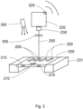
- Figure 3 shows a schematic representation of a second arrangement of optical components of a Preview Station.
- transmission light source 218 has been replaced by an epi light source (epi illuminator) 300 mounted to illuminate the slide tray and microscope slides from above.
- This arrangement also illuminates the barcodes on microscope slides and on the slide tray from above and in some situations will result in better images of the barcodes and data written on the microscope slides, which may be written on labels that are easier to image when illuminated from above.
- this arrangement is particularly useful for fluorescence imaging, where the illumination wavelength band of epi light source 300 is adjusted to match the excitation wavelength band of the fluorophores in use, and an emission filter 305 is inserted into the optical path in front of lens 230 to pass the fluorescence emission wavelengths from the specimen.
- fluorescence imaging it may be appropriate to replace colour camera 220 with a monochrome camera.
- Figure 4 shows a schematic representation of a third arrangement of optical components of a Preview Station, in which both transmission and epi illumination are available, either separately or in combination.
- emission filter 305 has been removed from the optical path, but can be replaced for fluorescence imaging using epi illuminator 300.
- This optical combination is particularly useful when an image using transmission illumination is best for tissue finding, and an image using epi illumination is best for fluorescence and for reading the tray barcode 210 and/or the barcodes and written information (sometimes on stickers) on microscope slides 200.
- One technique to produce a single image with good contrast for both the barcodes and tissue specimens is to acquire one image using transmission illuminator 218, and a second image using epi illuminator 300, then combine the two images digitally.
- One possibility is to simply digitally add the two images together on a pixel-by-pixel basis, since they are perfectly registered, and the areas of the microscope slides containing tissue will be much brighter in the transmission-illuminated image, while the areas containing barcodes and stickers will be brighter in the epi-illuminated image.
- Another possibility is to mask the epi-illuminated image to include only areas containing barcodes and written information, mask the transmission-illuminated image to include all other areas, then digitally add the two images together to produce a single image.
- FIG. 5 shows a schematic representation of a fourth arrangement of optical components of a Preview Station. This arrangement is functionally the same as that shown in Figure 4 , however transmission illumination source 218 has been replaced by transilluminator 500.
- Transilluminators sometimes called light boxes
- Transilluminators are often used when imaging gels in the laboratory, and are available as white light and/or UV illuminators, using either LED or incandescent sources, or fluorescent tubes placed below flat plate 505.
- Plate 505 may be constructed of transparent, translucent, fluorescent, or filter material.
- Plates can be removed and replaced to change the spectral characteristics of the transmission illumination, and/or the spectral characteristics can be changed by changing the illumination source (for example, a white light source can be constructed using arrays of red, green and blue LED's, and these three arrays can be activated separately or in combination).
- a white light source can be constructed using arrays of red, green and blue LED's, and these three arrays can be activated separately or in combination.
- Figure 6 shows a schematic representation of a first (preferred) embodiment of a Preview Station using the optical system comprised of the arrangement shown in Figure 5 .
- the preview station optical system 600 shown in this figure using dotted lines is comprised of the same components detailed in Figure 5 .
- a light-tight enclosure (or "hood") 610 contains a slot 615 for insertion and removal of slide tray 205.
- slides in slide tray 205 can be examined visually using illumination from transilluminator 500 and this provides a quick and easy method of quality control to find obvious flaws in microscope slide preparation even before using the Preview Station camera.
- hood 610 is placed over optical system 600 and slide tray 205 is inserted through slot 615.
- This embodiment does not have an integrated computer and viewing screen, so the camera can be triggered manually or set to automatically trigger a few seconds after insertion of a new slide tray (sensed using a mechanical switch, not shown in the Figure) or the camera can be triggered remotely using WiFi or a direct connection to a remote or local viewing station.
- the images can be stored in memory in the camera, and then transferred in a batch to a local or remote viewing station.
- a local or remote viewing station can be one of a desktop computer, a laptop computer, a tablet computer (like an iPad), a portable media player that includes a viewing screen that allows the operator to view and interact with an image on the screen, a smart phone, or other wireless or wired device that allows the operator to view and interact with an image of the microscope slide or slides, or the scanner's viewing station.
- a light-tight enclosure 610 can be added to each of the three optical component arrangements shown in Figures 2 , 3 and 4 to produce a second, third and fourth embodiment of a Preview Station.
- Figure 7 shows a schematic representation of a fifth (preferred) embodiment of a Preview Station using the optical system comprised of components shown in Figure 5 .
- the preview station optical system 600 shown in this figure using dotted lines is comprised of the same components detailed in Figure 5 .
- a light-tight enclosure 610 contains a slot 615 for insertion and removal of slide tray 205.
- a computerized viewing station 700 is mounted on top of light-tight enclosure 610.
- a light-tight door (not shown) in the front panel of enclosure 610 provides access to the light sources, camera and filter.
- the computerized viewing station mounted on top of enclosure 610 is comprised of an integrated computer that communicates with and controls the camera or cameras and light sources, stores images and metadata, and communicates with the scanner.
- Viewing screen 710 is a touch screen that enables the operator to view and interact with the computer and an image on the screen.
- AC power for the unit and control of the light sources may be achieved by using mechanical switches or controls 720, or using the touch screen.
- This fifth embodiment is a stand-alone preview station with all of the features and components required to allow the user to view and interact with images of the slide tray and individual slides, and to store and later communicate both preview images and data to the scanner.
- a light-tight enclosure 610 and computerized viewing station 700 can be added to each of the three optical component arrangements shown in Figures 2 , 3 and 4 to produce a sixth, seventh and eighth embodiment of a Preview Station that are also stand-alone instruments.
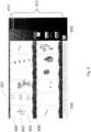
- Figure 8 shows one implementation of a viewing screen 800 that can be used on a stand-alone Preview Station or on the viewing screen of a remote or local viewing station.
- a series 810 of horizontal rectangles 815 represents the slides on the slide tray imaged on the screen.
- Small squares 830 represent the number of the slide tray being imaged (in this early implementation of a viewing screen the slide tray number was manually changed from 1 to 25 using button 832 - in later implementations the slide tray number is read from a barcode and displayed on the screen).
- Microscope slides 820 include tissue specimens 822 and slide barcodes 826 on each slide. The scan area is adjusted by changing the position of the sides of rectangle 824 that delimits the area to be scanned on the scanner.
- a zoom function allows the user to zoom in to increase the size of the view of each slide in the tray.
- Figure 9 shows one possible arrangement of a Preview Station and scanner. Note that in a large hospital or laboratory, one or more preview stations may be connected to one or more scanners.
- a Preview Station 901 reports preview image data, scan parameters, quality control (QC) information, and scan priority to a Scan Setup Workstation and Database 905 using wireless transmission 903 or through wired connection 904. (Note: In some implementations, the Preview Station sends only images to the Scan Setup Workstation and scan-setup information is produced in the Scan Setup Workstation.)
- Scan Setup Workstation and Database 905 is attached to a display 906, which may be separate from or internal to Workstation 905. Workstation 905 interacts with scanner 910 (or multiple scanners) through a Network 907, which may be wired or wireless.
- each may be set up for particular kinds of imaging in advance - for example one may be a fluorescence scanner, one may be a brightfield-only scanner, and one may be used only for highest priority scanning. Many combinations are possible.
- Slide trays are loaded into a scanner or into that scanner's autoloader after previewing in Preview Station 901.
- Scan Setup Workstation and Database 905 Using information stored in Scan Setup Workstation and Database 905, a scanner requests a particular slide tray, the autoloader loads that tray into the scanner, and scan commences. When scanning of the slides in that tray is completed, the Autoloader unloads the tray and places it in a "completed work" storage stack (not shown).
- Final scanned images and metadata for the slides in each tray are stored in Scan Setup Workstation and Database 905 and can be transmitted on request to a remote medical imaging station (not shown - in the physician's office for example) either wirelessly or by wire.
- Network 907 may be a wired or wireless network.
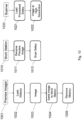
- FIG. 10 A first embodiment of a workflow for slide scanning using the Preview Station is shown in Figure 10 .
- the Preview Imager is used to image the sample(s) but scan setup information is generated from that image in a separate workstation, which sends the scan setup information on to the Scanner.
- This workflow decouples preview image generation (including imaging the barcode/label), decouples scan-setup, and decouples high resolution image acquisition, all from one another.
- the sample/sample holder is loaded 1002 into preview imager 1001 manually or automatically. After being loaded, an image 1003 of the samples is acquired and transmitted 1004 to a workstation 1010.
- the sample holder is then removed 1005 from the Preview Imager and can be loaded into the scanner 1020 or the scanner's autoloader.
- the received preview images 1011 are used to automatically or manually generate scan setup information 1012 to control the high-resolution scanner. Automatically generated scan-setup information can be reviewed and adjusted if necessary.
- the Preview Imager can be continuously transmitting additional images to the workstation.
- the workstation which also controls the scanner, uses the scan-setup information to acquire the specified high-resolution image.
- the workstation can be receiving additional preview images from the Preview Imager, and also be used to automatically or manually generate additional scan-setups.
- This arrangement parallelizes the processes of capturing preview images, generating scan-setups, and acquiring high-resolution images.
- This workflow does not impose physical attachment dependencies on the preview imager, for example, it can be an independent station or attached to the scanner.
- the preview imager may also be used to generate scan-setup information and while recognizing this would couple the generation of preview images with generation of scan-setups, it may be desirable under specific lab circumstances.
- the Preview Imager must have a screen for displaying preview images and the ability to generate scan-setup information, automatically or manually.
- FIG. 11 A second embodiment of a workflow is shown in Figure 11 .
- This workflow couples preview image generation (including barcode/label) with the generation of scan-setup information, and decouples high resolution image scanning.
- setting up a scan takes place immediately after capturing a preview image.
- the slide(s)/slide tray is loaded 1102 into the preview imager 1101 manually or automatically. After being loaded, an image of the slides is acquired and immediately displayed 1103.
- the preview images are used to automatically or manually create scan-setups 1104. Automatically generated scan-setups can be reviewed and adjusted if necessary. Then the preview image and scan-setups are transmitted to the workstation 1110.
- the slide tray is then removed from the Preview Imager and can be loaded 1121into the scanner/autoloader.
- the workstation which also controls the scanner 1120, uses the scan-setup information to direct the scanner acquire the specified high-resolution image. While the scanner is acquiring high-resolution images, the workstation can be receiving additional preview images and corresponding scan-setup information from the Preview Imager. This arrangement couples the process of capturing preview images and generating scan-setups however, de-couples the acquisition of high-resolution images. This second workflow does not impose physical attachment dependencies on the preview imager, for example, it can be an independent station or attached to the scanner.
- FIG. 12 A third embodiment of a workflow is shown in Figure 12 .
- all preview images are taken first, followed by setting up all scans.
- the slide(s)/slide tray is loaded into the preview imager manually or automatically. After being loaded, a preview image is acquired and stored. The slide tray is then removed from the Preview Imager and can be loaded into the scanner/autoloader. This process is repeated until all slides/slide trays are loaded and imaged.
- the preview images are used to automatically or manually create high-resolution scan-setups. Automatically generated scan-setups can be reviewed and adjusted if necessary. After a scan-setup is created, its corresponding preview image and the scan-setup are transmitted to the workstation.
- the Preview Station and Methods of Operation described in this patent document are useful for any imaging system in which a preview image of the specimen is required to set imaging or scan parameters before acquiring a high-resolution image using a scanner or other high-resolution large-area imager.
- the present invention will have application when imaging microwell plates, well plates, microarrays, and many others.
- the workstation receives preview images and can generate scan-setups and prioritizes scan-setups based on user specifications including predetermined configurable protocols, for example, FIFO (first-in-first-out).
- the autoloader is able to communicate with the workstation to determine which scan-setup is next in order and load the appropriate sample/sample holder into an available scanner. Scanners communicate with the autoloader updating their status indicating availability for scanning, the need for removal of scanned sample(s)/sample holder, whether they are busy scanning, and other relevant information.
- the Preview Imager and Methods of Operation described in this disclosure are useful for any imaging system in which a preview image of the specimen is required to set imaging or scan parameters before acquiring a high-resolution image using a scanner or other high-resolution large-area imager.
- the present invention will have application when imaging microwell plates, well plates, microarrays, and many others.
Landscapes
- Physics & Mathematics (AREA)
- Chemical & Material Sciences (AREA)
- Analytical Chemistry (AREA)
- General Physics & Mathematics (AREA)
- Optics & Photonics (AREA)
- Engineering & Computer Science (AREA)
- Multimedia (AREA)
- Computer Vision & Pattern Recognition (AREA)
- Signal Processing (AREA)
- Microscoopes, Condenser (AREA)
Claims (13)
- Poste de prévisualisation (700) pour prévisualiser un plateau de lames (205), le poste de prévisualisation comprenant un support de plateau (231) et un plateau de lames (205), le support de plateau étant configuré pour soutenir le plateau de lames (205), le plateau de lames (205) portant sur lui une pluralité de lames de microscope (200), une source d'éclairage (300) pour illuminer le plateau de lames (205), chaque lame de microscope (200) portant sur elle un échantillon (822), une caméra numérique (220) et une lentille (230) localisées sur un axe optique (250) relativement au plateau de lames (205), la caméra numérique (220) et le plateau de lames (205) étant fixes relativement l'un à l'autre, et configurés pour capturer une image individuelle de prévisualisation montrant le plateau de lames et chaque lame de microscope (200), où une focalisation de la lentille (230) est fixée pour imager le plateau de lames (205) et les lames de microscope (200) sur celui-ci de manière simultanée dans ladite image individuelle de prévisualisation une fois que la caméra (220) a été activée ; le plateau de lames comportant un codes-barres de plateau (210) et chaque lame de microscope ayant un code-barres de lame respectif (826), la caméra ayant une mémoire (225) pour stocker des données de l'image individuelle de prévisualisation montrant chaque lame (200) de la pluralité de lames de microscope sur le plateau de lames, chaque code-barres de lame respectif et le code-barres de plateau de lames, et un processeur d'ordinateur configuré pour obtenir automatiquement des données séparées pour chaque lame de microscope (200) en choisissant automatiquement une zone de balayage sur chaque lame de microscope (200) à partir de l'image individuelle de prévisualisation ; traiter les données pour chaque lame de microscope (200) à partir de l'image individuelle de prévisualisation ; traiter les données de code-barres à partir des codes-barres de lame respectifs et le code-barres de plateau de lames ; et transmettre les données pour chaque lame de microscope provenant de l'image individuelle de prévisualisation et les données de code-barres pour établir un balayage à haute résolution de la zone de balayage de chaque lame de microscope (200).
- Poste de prévisualisation (700) tel que revendiqué dans la revendication 1, où le processeur d'ordinateur est configuré pour choisir automatiquement une localisation pour régler une balance des blancs à l'intérieur de la zone de balayage devant être balayée pour chaque lame de microscope (200) de la pluralité de lames de microscope.
- Poste de prévisualisation (700) tel que revendiqué dans la revendication 1, comprenant en outre un affichage (710, 800) configuré pour afficher l'image individuelle de prévisualisation de chaque lame (200) de la pluralité de lames de microscope.
- Poste de prévisualisation (700) tel que revendiqué dans la revendication 3 où l'affichage est sélectionné parmi le groupe consistant en un écran sur un bureau, un portable laptop, une tablette, une phablette et un téléphone intelligent.
- Poste de prévisualisation (700) tel que revendiqué dans la revendication 1 où la source d'éclairage (300) est localisée au-dessus du support de plateau (231) et est configurée pour illuminer le plateau de lames (205) tout entier et chaque lame de microscope (200) sur celui-ci.
- Poste de prévisualisation (700) tel que revendiqué dans la revendication 5, où la source d'éclairage (300) est une première source d'éclairage, une deuxième source d'éclairage (218) est localisée en dessous du support de plateau (231) et le support de plateau est ouvert pour permettre à la lumière provenant de la deuxième source d'éclairage de passer à travers le support de plateau et l'échantillon sur chaque lame.
- Poste de prévisualisation (700) tel que revendiqué dans la revendication 1, le poste de prévisualisation étant configuré pour transmettre des données provenant de chaque lame (200) prévisualisée par le poste de prévisualisation (901) et l'image individuelle à un appareil de balayage (910) d'un système de balayage.
- Poste de prévisualisation (700) tel que revendiqué dans la revendication 1 et pluralité de plateaux de lames (205) qui chacun portent sur lui une pluralité de lames de microscope (200), la pluralité de plateaux de lames (205) étant montés sur le support de plateau (231) en succession, la caméra (220) étant configurée pour être activée pour capturer une image de chaque plateau de lames (205) et des lames de microscope sur celui-ci.
- Procédé de prévisualisation d'un plateau de lames (205) portant sur lui une pluralité de lames de microscope (200) grâce à l'utilisation d'un poste de prévisualisation selon la revendication 1, le procédé comprenant le fait de localiser la source d'éclairage (300) pour illuminer le plateau de lames (205), le fait de localiser la caméra et la lentille sur un axe optique (250), et le fait de focaliser la lentille (230) et le fait d'activer la caméra (220) pour imager le plateau de lames (205) et les lames de microscope (200) sur celui-ci de manière simultanée dans une image individuelle de prévisualisation, le fait d'utiliser le processeur d'ordinateur pour obtenir automatiquement des données séparées pour chaque lame de microscope (200) en choisissant une zone de balayage, incluant l'échantillon, sur chaque lame de microscope à partir de l'image individuelle de prévisualisation et pour traiter les données séparées pour chaque lame de microscope (200) à partir de l'image individuelle de prévisualisation et les données de code-barres à partir des codes-barres de lame respectifs et du code-barres de plateau de lames pour établir un balayage à haute résolution, et le fait de stocker les données pour chaque lame de microscope (200) ayant été imagée et le fait de transmettre les données pour chaque image.
- Procédé tel que revendiqué dans la revendication 9 incluant l'étape consistant à localiser la source d'éclairage (300) au-dessus du support de plateau.
- Procédé tel que revendiqué dans la revendication 9 incluant l'étape consistant à localiser la source d'éclairage (218) en dessous du support de plateau
- Poste de prévisualisation (901) tel que revendiqué dans la revendication 1 et système de balayage (910) en combinaison pour prévisualiser et balayer la pluralité de lames de microscope (200), où :a. la mémoire de caméra est configurée pour stocker et transmettre les données provenant de chaque lame de microscope dans le plateau de lames vers le système de balayage ;b. le poste de prévisualisation est configuré pour obtenir des données comportant des informations de l'échantillon et des informations de protocole balayées ;c. le poste de balayage est configuré pour recevoir des données provenant du poste de prévisualisation comprenant des informations décrivant les zones devant être balayées sur chaque échantillon, les positions de focalisation pour une focalisation automatique, des informations d'échantillon pour choisir les paramètres d'illumination et de détection pour une imagerie en champ clair ou à fluorescence, et une priorité de balayage pour chaque lame, le système de balayage étant apte à fonctionner indépendamment et simultanément avec le poste de prévisualisation.
- Procédé tel que revendiqué dans la revendication 9, comprenant en outre le fait de transférer des informations de protocole de balayage à partir du poste de prévisualisation (901) jusqu'à un système de balayage (910), le système de balayage comprenant un appareil de balayage, les informations de protocole de balayage fournissant à l'appareil de balayage une ou plusieurs descriptions de zones devant être balayées sur chaque échantillon, les positions de focalisation pour une focalisation automatique, les informations d'échantillon pour choisir l'illumination et les paramètres de détection pour une imagerie en champ clair ou à fluorescence, et une priorité de balayage pour chaque lame, en vertu de quoi l'appareil de balayage est en fonctionnement continu durant le fonctionnement du poste de prévisualisation et le balayage des lames chargées précédemment peut continuer sans interruption durant la prévisualisation.
Applications Claiming Priority (2)
| Application Number | Priority Date | Filing Date | Title |
|---|---|---|---|
| US201361839500P | 2013-06-26 | 2013-06-26 | |
| PCT/CA2014/000542 WO2014205557A1 (fr) | 2013-06-26 | 2014-06-26 | Poste de prévisualisation et procédé de capture d'images de prévisualisation de lames de microscope |
Publications (3)
| Publication Number | Publication Date |
|---|---|
| EP3014331A1 EP3014331A1 (fr) | 2016-05-04 |
| EP3014331A4 EP3014331A4 (fr) | 2017-01-25 |
| EP3014331B1 true EP3014331B1 (fr) | 2025-01-29 |
Family
ID=52140709
Family Applications (1)
| Application Number | Title | Priority Date | Filing Date |
|---|---|---|---|
| EP14818171.2A Active EP3014331B1 (fr) | 2013-06-26 | 2014-06-26 | Poste de prévisualisation et procédé de capture d'images de prévisualisation de lames de microscope |
Country Status (4)
| Country | Link |
|---|---|
| US (1) | US10088655B2 (fr) |
| EP (1) | EP3014331B1 (fr) |
| CA (1) | CA2916768A1 (fr) |
| WO (1) | WO2014205557A1 (fr) |
Families Citing this family (22)
| Publication number | Priority date | Publication date | Assignee | Title |
|---|---|---|---|---|
| EP3008667B1 (fr) | 2013-06-14 | 2019-01-16 | Agilent Technologies, Inc. | Système et procédé pour faciliter le tri manuel d'objets |
| JP6469977B2 (ja) * | 2014-07-09 | 2019-02-13 | オリンパス株式会社 | 標本観察装置および標本観察方法 |
| US10853625B2 (en) | 2015-03-21 | 2020-12-01 | Mine One Gmbh | Facial signature methods, systems and software |
| US10217011B2 (en) * | 2016-04-15 | 2019-02-26 | Agilent Technologies, Inc. | Apparatus and method for facilitating manual sorting of slides |
| US11079388B2 (en) * | 2016-04-26 | 2021-08-03 | Ultivue, Inc. | Super-resolution immunofluorescence with diffraction-limited preview |
| WO2018019973A1 (fr) | 2016-07-28 | 2018-02-01 | Koninklijke Philips N.V. | Balayage de lame à flux de production optimisé |
| EP3538941B1 (fr) | 2016-11-10 | 2025-04-23 | The Trustees of Columbia University in the City of New York | Procédés d'imagerie rapide de grands échantillons à haute résolution |
| CN110140129B (zh) | 2016-12-30 | 2023-10-17 | 徕卡生物系统成像股份有限公司 | 使用双光学路径和单成像传感器的低分辨率载片成像和载片标签成像以及高分辨率载片成像 |
| US12484884B2 (en) | 2017-10-09 | 2025-12-02 | Sakura Finetek U.S.A., Inc. | Tissue cassette reader |
| WO2019170564A1 (fr) * | 2018-03-06 | 2019-09-12 | Ventana Medical Systems, Inc. | Interface de balayage numérique de pathologie et flux de travaux |
| WO2019226688A1 (fr) | 2018-05-22 | 2019-11-28 | Agilent Technologies, Inc. | Procédé et système pour mettre en œuvre une assistance à base de réalité augmentée (ar) dans un environnement de travail |
| CN109491177A (zh) * | 2018-10-23 | 2019-03-19 | 杭州智微信息科技有限公司 | 数字智能采集系统全局盒 |
| CN111381355B (zh) * | 2018-12-29 | 2022-08-02 | 北京雅谱光仪科技有限公司 | 光学成像装置和方法 |
| US10805587B1 (en) * | 2019-07-09 | 2020-10-13 | Zebra Technologies Corporation | System and methods for enabling automatic white balance correction for color cameras |
| EP3839596B1 (fr) * | 2019-12-20 | 2023-08-23 | Euroimmun Medizinische Labordiagnostika AG | Dispositif et procédé d'identification de zones de verre de recouvrement d'une lame porte-objet |
| EP4127730B1 (fr) * | 2020-03-27 | 2026-04-29 | F. Hoffmann-La Roche AG | Appareil d'imagerie de diapositives et procédé d'imagerie d'une de diapositive |
| US12387522B2 (en) * | 2020-09-28 | 2025-08-12 | Vectech | Apparatus and method of mosquito identification |
| EP4057047A1 (fr) * | 2021-03-09 | 2022-09-14 | Leica Instruments (Singapore) Pte. Ltd. | Système de microscope et système, procédé et programme informatique correspondants |
| WO2022204248A1 (fr) * | 2021-03-23 | 2022-09-29 | Optiva Fertility, Inc. | Systèmes de microscope d'imagerie à durée de vie de fluorescence et procédés de fonctionnement de ceux-ci |
| US12566325B2 (en) * | 2023-04-28 | 2026-03-03 | S Amirdin Badri | Apparatus providing repeatable registration by aligning objects to be imaged |
| KR102648424B1 (ko) * | 2023-06-21 | 2024-03-15 | 주식회사 큐리오시스 | 슬라이드 정보를 디스플레이하는 장치 및 방법 |
| US20260023026A1 (en) * | 2024-07-16 | 2026-01-22 | Pramana, Inc. | Methods and apparatus for adaptive slide imaging using a selected scanning profile |
Citations (1)
| Publication number | Priority date | Publication date | Assignee | Title |
|---|---|---|---|---|
| JP2011212013A (ja) * | 2010-03-17 | 2011-10-27 | Elmex Ltd | フィルム型培地による微生物検査方法およびこの微生物検査方法に用いる画像取込ツ−ル |
Family Cites Families (6)
| Publication number | Priority date | Publication date | Assignee | Title |
|---|---|---|---|---|
| US5428690A (en) * | 1991-09-23 | 1995-06-27 | Becton Dickinson And Company | Method and apparatus for automated assay of biological specimens |
| US7133543B2 (en) * | 2001-06-12 | 2006-11-07 | Applied Imaging Corporation | Automated scanning method for pathology samples |
| US20030193567A1 (en) * | 2002-04-12 | 2003-10-16 | Hubel Paul M. | Digital camera media scanning methods, digital image processing methods, digital camera media scanning systems, and digital imaging systems |
| US20050037406A1 (en) * | 2002-06-12 | 2005-02-17 | De La Torre-Bueno Jose | Methods and apparatus for analysis of a biological specimen |
| US20070140543A1 (en) * | 2005-12-19 | 2007-06-21 | Cytyc Corporation | Systems and methods for enhanced cytological specimen review |
| US10139613B2 (en) | 2010-08-20 | 2018-11-27 | Sakura Finetek U.S.A., Inc. | Digital microscope and method of sensing an image of a tissue sample |
-
2014
- 2014-06-26 EP EP14818171.2A patent/EP3014331B1/fr active Active
- 2014-06-26 US US14/901,469 patent/US10088655B2/en active Active
- 2014-06-26 CA CA2916768A patent/CA2916768A1/fr not_active Abandoned
- 2014-06-26 WO PCT/CA2014/000542 patent/WO2014205557A1/fr not_active Ceased
Patent Citations (1)
| Publication number | Priority date | Publication date | Assignee | Title |
|---|---|---|---|---|
| JP2011212013A (ja) * | 2010-03-17 | 2011-10-27 | Elmex Ltd | フィルム型培地による微生物検査方法およびこの微生物検査方法に用いる画像取込ツ−ル |
Also Published As
| Publication number | Publication date |
|---|---|
| EP3014331A1 (fr) | 2016-05-04 |
| CA2916768A1 (fr) | 2014-12-31 |
| US20160139387A1 (en) | 2016-05-19 |
| WO2014205557A1 (fr) | 2014-12-31 |
| EP3014331A4 (fr) | 2017-01-25 |
| US10088655B2 (en) | 2018-10-02 |
Similar Documents
| Publication | Publication Date | Title |
|---|---|---|
| EP3014331B1 (fr) | Poste de prévisualisation et procédé de capture d'images de prévisualisation de lames de microscope | |
| US11597612B2 (en) | Slide rack gripper apparatus | |
| CN114200660B (zh) | 载片卡死确定系统 | |
| US9110306B2 (en) | Tissue-slice image acquirement and display apparatus, tissue-slice image acquirement and display method, and tissue-slice image acquirement and display program | |
| US11921125B2 (en) | Slide inventory and reinsertion system | |
| JP2020507106A (ja) | 二重光学経路および単一撮像センサを使用した低解像度スライド撮像、スライドラベル撮像および高解像度スライド撮像 | |
| JP5677770B2 (ja) | 医療診断支援装置、バーチャル顕微鏡システムおよび標本支持部材 | |
| CN111527438A (zh) | 冲击重新扫描系统 | |
| US8994806B2 (en) | Microscope apparatus chronologically storing different types of image information | |
| US20200184167A1 (en) | Workflow optimized slide scanning | |
| CN114441260B (zh) | 载片架确定系统 | |
| US8913819B2 (en) | Observation apparatus and observation method | |
| JP2025540372A (ja) | スライドスキャン装置およびその動作方法 |
Legal Events
| Date | Code | Title | Description |
|---|---|---|---|
| PUAI | Public reference made under article 153(3) epc to a published international application that has entered the european phase |
Free format text: ORIGINAL CODE: 0009012 |
|
| 17P | Request for examination filed |
Effective date: 20160118 |
|
| AK | Designated contracting states |
Kind code of ref document: A1 Designated state(s): AL AT BE BG CH CY CZ DE DK EE ES FI FR GB GR HR HU IE IS IT LI LT LU LV MC MK MT NL NO PL PT RO RS SE SI SK SM TR |
|
| AX | Request for extension of the european patent |
Extension state: BA ME |
|
| DAX | Request for extension of the european patent (deleted) | ||
| A4 | Supplementary search report drawn up and despatched |
Effective date: 20170102 |
|
| RIC1 | Information provided on ipc code assigned before grant |
Ipc: G02B 21/36 20060101AFI20161221BHEP Ipc: G02B 21/34 20060101ALI20161221BHEP |
|
| STAA | Information on the status of an ep patent application or granted ep patent |
Free format text: STATUS: EXAMINATION IS IN PROGRESS |
|
| 17Q | First examination report despatched |
Effective date: 20200702 |
|
| GRAP | Despatch of communication of intention to grant a patent |
Free format text: ORIGINAL CODE: EPIDOSNIGR1 |
|
| STAA | Information on the status of an ep patent application or granted ep patent |
Free format text: STATUS: GRANT OF PATENT IS INTENDED |
|
| INTG | Intention to grant announced |
Effective date: 20240618 |
|
| GRAS | Grant fee paid |
Free format text: ORIGINAL CODE: EPIDOSNIGR3 |
|
| GRAA | (expected) grant |
Free format text: ORIGINAL CODE: 0009210 |
|
| STAA | Information on the status of an ep patent application or granted ep patent |
Free format text: STATUS: THE PATENT HAS BEEN GRANTED |
|
| AK | Designated contracting states |
Kind code of ref document: B1 Designated state(s): AL AT BE BG CH CY CZ DE DK EE ES FI FR GB GR HR HU IE IS IT LI LT LU LV MC MK MT NL NO PL PT RO RS SE SI SK SM TR |
|
| REG | Reference to a national code |
Ref country code: GB Ref legal event code: FG4D |
|
| REG | Reference to a national code |
Ref country code: CH Ref legal event code: EP |
|
| REG | Reference to a national code |
Ref country code: DE Ref legal event code: R096 Ref document number: 602014091504 Country of ref document: DE |
|
| REG | Reference to a national code |
Ref country code: IE Ref legal event code: FG4D |
|
| REG | Reference to a national code |
Ref country code: NL Ref legal event code: MP Effective date: 20250129 |
|
| PG25 | Lapsed in a contracting state [announced via postgrant information from national office to epo] |
Ref country code: NL Free format text: LAPSE BECAUSE OF FAILURE TO SUBMIT A TRANSLATION OF THE DESCRIPTION OR TO PAY THE FEE WITHIN THE PRESCRIBED TIME-LIMIT Effective date: 20250129 |
|
| PG25 | Lapsed in a contracting state [announced via postgrant information from national office to epo] |
Ref country code: RS Free format text: LAPSE BECAUSE OF FAILURE TO SUBMIT A TRANSLATION OF THE DESCRIPTION OR TO PAY THE FEE WITHIN THE PRESCRIBED TIME-LIMIT Effective date: 20250429 |
|
| PG25 | Lapsed in a contracting state [announced via postgrant information from national office to epo] |
Ref country code: FI Free format text: LAPSE BECAUSE OF FAILURE TO SUBMIT A TRANSLATION OF THE DESCRIPTION OR TO PAY THE FEE WITHIN THE PRESCRIBED TIME-LIMIT Effective date: 20250129 |
|
| PG25 | Lapsed in a contracting state [announced via postgrant information from national office to epo] |
Ref country code: PL Free format text: LAPSE BECAUSE OF FAILURE TO SUBMIT A TRANSLATION OF THE DESCRIPTION OR TO PAY THE FEE WITHIN THE PRESCRIBED TIME-LIMIT Effective date: 20250129 |
|
| PGFP | Annual fee paid to national office [announced via postgrant information from national office to epo] |
Ref country code: DE Payment date: 20250626 Year of fee payment: 12 |
|
| PG25 | Lapsed in a contracting state [announced via postgrant information from national office to epo] |
Ref country code: ES Free format text: LAPSE BECAUSE OF FAILURE TO SUBMIT A TRANSLATION OF THE DESCRIPTION OR TO PAY THE FEE WITHIN THE PRESCRIBED TIME-LIMIT Effective date: 20250129 |
|
| PGFP | Annual fee paid to national office [announced via postgrant information from national office to epo] |
Ref country code: GB Payment date: 20250625 Year of fee payment: 12 |
|
| REG | Reference to a national code |
Ref country code: LT Ref legal event code: MG9D |
|
| PG25 | Lapsed in a contracting state [announced via postgrant information from national office to epo] |
Ref country code: IS Free format text: LAPSE BECAUSE OF FAILURE TO SUBMIT A TRANSLATION OF THE DESCRIPTION OR TO PAY THE FEE WITHIN THE PRESCRIBED TIME-LIMIT Effective date: 20250529 Ref country code: NO Free format text: LAPSE BECAUSE OF FAILURE TO SUBMIT A TRANSLATION OF THE DESCRIPTION OR TO PAY THE FEE WITHIN THE PRESCRIBED TIME-LIMIT Effective date: 20250429 |
|
| REG | Reference to a national code |
Ref country code: AT Ref legal event code: MK05 Ref document number: 1764009 Country of ref document: AT Kind code of ref document: T Effective date: 20250129 |
|
| PG25 | Lapsed in a contracting state [announced via postgrant information from national office to epo] |
Ref country code: HR Free format text: LAPSE BECAUSE OF FAILURE TO SUBMIT A TRANSLATION OF THE DESCRIPTION OR TO PAY THE FEE WITHIN THE PRESCRIBED TIME-LIMIT Effective date: 20250129 |
|
| PG25 | Lapsed in a contracting state [announced via postgrant information from national office to epo] |
Ref country code: PT Free format text: LAPSE BECAUSE OF FAILURE TO SUBMIT A TRANSLATION OF THE DESCRIPTION OR TO PAY THE FEE WITHIN THE PRESCRIBED TIME-LIMIT Effective date: 20250529 Ref country code: LV Free format text: LAPSE BECAUSE OF FAILURE TO SUBMIT A TRANSLATION OF THE DESCRIPTION OR TO PAY THE FEE WITHIN THE PRESCRIBED TIME-LIMIT Effective date: 20250129 |
|
| PG25 | Lapsed in a contracting state [announced via postgrant information from national office to epo] |
Ref country code: GR Free format text: LAPSE BECAUSE OF FAILURE TO SUBMIT A TRANSLATION OF THE DESCRIPTION OR TO PAY THE FEE WITHIN THE PRESCRIBED TIME-LIMIT Effective date: 20250430 Ref country code: BG Free format text: LAPSE BECAUSE OF FAILURE TO SUBMIT A TRANSLATION OF THE DESCRIPTION OR TO PAY THE FEE WITHIN THE PRESCRIBED TIME-LIMIT Effective date: 20250129 |
|
| PG25 | Lapsed in a contracting state [announced via postgrant information from national office to epo] |
Ref country code: AT Free format text: LAPSE BECAUSE OF FAILURE TO SUBMIT A TRANSLATION OF THE DESCRIPTION OR TO PAY THE FEE WITHIN THE PRESCRIBED TIME-LIMIT Effective date: 20250129 |
|
| PG25 | Lapsed in a contracting state [announced via postgrant information from national office to epo] |
Ref country code: SE Free format text: LAPSE BECAUSE OF FAILURE TO SUBMIT A TRANSLATION OF THE DESCRIPTION OR TO PAY THE FEE WITHIN THE PRESCRIBED TIME-LIMIT Effective date: 20250129 |
|
| PG25 | Lapsed in a contracting state [announced via postgrant information from national office to epo] |
Ref country code: SM Free format text: LAPSE BECAUSE OF FAILURE TO SUBMIT A TRANSLATION OF THE DESCRIPTION OR TO PAY THE FEE WITHIN THE PRESCRIBED TIME-LIMIT Effective date: 20250129 |
|
| PG25 | Lapsed in a contracting state [announced via postgrant information from national office to epo] |
Ref country code: DK Free format text: LAPSE BECAUSE OF FAILURE TO SUBMIT A TRANSLATION OF THE DESCRIPTION OR TO PAY THE FEE WITHIN THE PRESCRIBED TIME-LIMIT Effective date: 20250129 |
|
| PG25 | Lapsed in a contracting state [announced via postgrant information from national office to epo] |
Ref country code: IT Free format text: LAPSE BECAUSE OF FAILURE TO SUBMIT A TRANSLATION OF THE DESCRIPTION OR TO PAY THE FEE WITHIN THE PRESCRIBED TIME-LIMIT Effective date: 20250129 |
|
| PG25 | Lapsed in a contracting state [announced via postgrant information from national office to epo] |
Ref country code: CZ Free format text: LAPSE BECAUSE OF FAILURE TO SUBMIT A TRANSLATION OF THE DESCRIPTION OR TO PAY THE FEE WITHIN THE PRESCRIBED TIME-LIMIT Effective date: 20250129 Ref country code: EE Free format text: LAPSE BECAUSE OF FAILURE TO SUBMIT A TRANSLATION OF THE DESCRIPTION OR TO PAY THE FEE WITHIN THE PRESCRIBED TIME-LIMIT Effective date: 20250129 |
|
| PG25 | Lapsed in a contracting state [announced via postgrant information from national office to epo] |
Ref country code: RO Free format text: LAPSE BECAUSE OF FAILURE TO SUBMIT A TRANSLATION OF THE DESCRIPTION OR TO PAY THE FEE WITHIN THE PRESCRIBED TIME-LIMIT Effective date: 20250129 |
|
| PG25 | Lapsed in a contracting state [announced via postgrant information from national office to epo] |
Ref country code: SK Free format text: LAPSE BECAUSE OF FAILURE TO SUBMIT A TRANSLATION OF THE DESCRIPTION OR TO PAY THE FEE WITHIN THE PRESCRIBED TIME-LIMIT Effective date: 20250129 |
|
| REG | Reference to a national code |
Ref country code: DE Ref legal event code: R097 Ref document number: 602014091504 Country of ref document: DE |
|
| PLBE | No opposition filed within time limit |
Free format text: ORIGINAL CODE: 0009261 |
|
| STAA | Information on the status of an ep patent application or granted ep patent |
Free format text: STATUS: NO OPPOSITION FILED WITHIN TIME LIMIT |
|
| REG | Reference to a national code |
Ref country code: CH Ref legal event code: L10 Free format text: ST27 STATUS EVENT CODE: U-0-0-L10-L00 (AS PROVIDED BY THE NATIONAL OFFICE) Effective date: 20251210 |
|
| 26N | No opposition filed |
Effective date: 20251030 |
|
| REG | Reference to a national code |
Ref country code: CH Ref legal event code: H13 Free format text: ST27 STATUS EVENT CODE: U-0-0-H10-H13 (AS PROVIDED BY THE NATIONAL OFFICE) Effective date: 20260127 |
|
| PG25 | Lapsed in a contracting state [announced via postgrant information from national office to epo] |
Ref country code: MC Free format text: LAPSE BECAUSE OF FAILURE TO SUBMIT A TRANSLATION OF THE DESCRIPTION OR TO PAY THE FEE WITHIN THE PRESCRIBED TIME-LIMIT Effective date: 20250129 |
|
| PG25 | Lapsed in a contracting state [announced via postgrant information from national office to epo] |
Ref country code: LU Free format text: LAPSE BECAUSE OF NON-PAYMENT OF DUE FEES Effective date: 20250626 |
|
| REG | Reference to a national code |
Ref country code: BE Ref legal event code: MM Effective date: 20250630 |
|
| PG25 | Lapsed in a contracting state [announced via postgrant information from national office to epo] |
Ref country code: IE Free format text: LAPSE BECAUSE OF NON-PAYMENT OF DUE FEES Effective date: 20250626 |
|
| PG25 | Lapsed in a contracting state [announced via postgrant information from national office to epo] |
Ref country code: BE Free format text: LAPSE BECAUSE OF NON-PAYMENT OF DUE FEES Effective date: 20250630 |
|
| PG25 | Lapsed in a contracting state [announced via postgrant information from national office to epo] |
Ref country code: FR Free format text: LAPSE BECAUSE OF NON-PAYMENT OF DUE FEES Effective date: 20250630 |
|
| PG25 | Lapsed in a contracting state [announced via postgrant information from national office to epo] |
Ref country code: CH Free format text: LAPSE BECAUSE OF NON-PAYMENT OF DUE FEES Effective date: 20250630 |