EP3014720B1 - Bobine de câble à verrouillage de station de charge pour véhicule électrique - Google Patents
Bobine de câble à verrouillage de station de charge pour véhicule électrique Download PDFInfo
- Publication number
- EP3014720B1 EP3014720B1 EP13887645.3A EP13887645A EP3014720B1 EP 3014720 B1 EP3014720 B1 EP 3014720B1 EP 13887645 A EP13887645 A EP 13887645A EP 3014720 B1 EP3014720 B1 EP 3014720B1
- Authority
- EP
- European Patent Office
- Prior art keywords
- cable
- reel
- assembly
- conductive member
- evse
- Prior art date
- Legal status (The legal status is an assumption and is not a legal conclusion. Google has not performed a legal analysis and makes no representation as to the accuracy of the status listed.)
- Active
Links
Images
Classifications
-
- B—PERFORMING OPERATIONS; TRANSPORTING
- B60—VEHICLES IN GENERAL
- B60L—PROPULSION OF ELECTRICALLY-PROPELLED VEHICLES; SUPPLYING ELECTRIC POWER FOR AUXILIARY EQUIPMENT OF ELECTRICALLY-PROPELLED VEHICLES; ELECTRODYNAMIC BRAKE SYSTEMS FOR VEHICLES IN GENERAL; MAGNETIC SUSPENSION OR LEVITATION FOR VEHICLES; MONITORING OPERATING VARIABLES OF ELECTRICALLY-PROPELLED VEHICLES; ELECTRIC SAFETY DEVICES FOR ELECTRICALLY-PROPELLED VEHICLES
- B60L53/00—Methods of charging batteries, specially adapted for electric vehicles; Charging stations or on-board charging equipment therefor; Exchange of energy storage elements in electric vehicles
- B60L53/30—Constructional details of charging stations
- B60L53/31—Charging columns specially adapted for electric vehicles
-
- H—ELECTRICITY
- H01—ELECTRIC ELEMENTS
- H01H—ELECTRIC SWITCHES; RELAYS; SELECTORS; EMERGENCY PROTECTIVE DEVICES
- H01H3/00—Mechanisms for operating contacts
- H01H3/02—Operating parts, i.e. for operating driving mechanism by a mechanical force external to the switch
- H01H3/16—Operating parts, i.e. for operating driving mechanism by a mechanical force external to the switch adapted for actuation at a limit or other predetermined position in the path of a body, the relative movement of switch and body being primarily for a purpose other than the actuation of the switch, e.g. for a door switch, a limit switch, a floor-levelling switch of a lift
-
- B—PERFORMING OPERATIONS; TRANSPORTING
- B60—VEHICLES IN GENERAL
- B60L—PROPULSION OF ELECTRICALLY-PROPELLED VEHICLES; SUPPLYING ELECTRIC POWER FOR AUXILIARY EQUIPMENT OF ELECTRICALLY-PROPELLED VEHICLES; ELECTRODYNAMIC BRAKE SYSTEMS FOR VEHICLES IN GENERAL; MAGNETIC SUSPENSION OR LEVITATION FOR VEHICLES; MONITORING OPERATING VARIABLES OF ELECTRICALLY-PROPELLED VEHICLES; ELECTRIC SAFETY DEVICES FOR ELECTRICALLY-PROPELLED VEHICLES
- B60L53/00—Methods of charging batteries, specially adapted for electric vehicles; Charging stations or on-board charging equipment therefor; Exchange of energy storage elements in electric vehicles
- B60L53/10—Methods of charging batteries, specially adapted for electric vehicles; Charging stations or on-board charging equipment therefor; Exchange of energy storage elements in electric vehicles characterised by the energy transfer between the charging station and the vehicle
- B60L53/14—Conductive energy transfer
- B60L53/16—Connectors, e.g. plugs or sockets, specially adapted for charging electric vehicles
-
- B—PERFORMING OPERATIONS; TRANSPORTING
- B60—VEHICLES IN GENERAL
- B60L—PROPULSION OF ELECTRICALLY-PROPELLED VEHICLES; SUPPLYING ELECTRIC POWER FOR AUXILIARY EQUIPMENT OF ELECTRICALLY-PROPELLED VEHICLES; ELECTRODYNAMIC BRAKE SYSTEMS FOR VEHICLES IN GENERAL; MAGNETIC SUSPENSION OR LEVITATION FOR VEHICLES; MONITORING OPERATING VARIABLES OF ELECTRICALLY-PROPELLED VEHICLES; ELECTRIC SAFETY DEVICES FOR ELECTRICALLY-PROPELLED VEHICLES
- B60L53/00—Methods of charging batteries, specially adapted for electric vehicles; Charging stations or on-board charging equipment therefor; Exchange of energy storage elements in electric vehicles
- B60L53/10—Methods of charging batteries, specially adapted for electric vehicles; Charging stations or on-board charging equipment therefor; Exchange of energy storage elements in electric vehicles characterised by the energy transfer between the charging station and the vehicle
- B60L53/14—Conductive energy transfer
- B60L53/18—Cables specially adapted for charging electric vehicles
-
- H—ELECTRICITY
- H02—GENERATION; CONVERSION OR DISTRIBUTION OF ELECTRIC POWER
- H02G—INSTALLATION OF ELECTRIC CABLES OR LINES, OR OF COMBINED OPTICAL AND ELECTRIC CABLES OR LINES
- H02G11/00—Arrangements of electric cables or lines between relatively-movable parts
- H02G11/02—Arrangements of electric cables or lines between relatively-movable parts using take-up reel or drum
-
- H—ELECTRICITY
- H02—GENERATION; CONVERSION OR DISTRIBUTION OF ELECTRIC POWER
- H02G—INSTALLATION OF ELECTRIC CABLES OR LINES, OR OF COMBINED OPTICAL AND ELECTRIC CABLES OR LINES
- H02G3/00—Installations of electric cables or lines or protective tubing therefor in or on buildings, equivalent structures or vehicles
- H02G3/02—Details
- H02G3/04—Protective tubing or conduits, e.g. cable ladders or cable troughs
- H02G3/0493—Service poles
-
- Y—GENERAL TAGGING OF NEW TECHNOLOGICAL DEVELOPMENTS; GENERAL TAGGING OF CROSS-SECTIONAL TECHNOLOGIES SPANNING OVER SEVERAL SECTIONS OF THE IPC; TECHNICAL SUBJECTS COVERED BY FORMER USPC CROSS-REFERENCE ART COLLECTIONS [XRACs] AND DIGESTS
- Y02—TECHNOLOGIES OR APPLICATIONS FOR MITIGATION OR ADAPTATION AGAINST CLIMATE CHANGE
- Y02T—CLIMATE CHANGE MITIGATION TECHNOLOGIES RELATED TO TRANSPORTATION
- Y02T10/00—Road transport of goods or passengers
- Y02T10/60—Other road transportation technologies with climate change mitigation effect
- Y02T10/70—Energy storage systems for electromobility, e.g. batteries
-
- Y—GENERAL TAGGING OF NEW TECHNOLOGICAL DEVELOPMENTS; GENERAL TAGGING OF CROSS-SECTIONAL TECHNOLOGIES SPANNING OVER SEVERAL SECTIONS OF THE IPC; TECHNICAL SUBJECTS COVERED BY FORMER USPC CROSS-REFERENCE ART COLLECTIONS [XRACs] AND DIGESTS
- Y02—TECHNOLOGIES OR APPLICATIONS FOR MITIGATION OR ADAPTATION AGAINST CLIMATE CHANGE
- Y02T—CLIMATE CHANGE MITIGATION TECHNOLOGIES RELATED TO TRANSPORTATION
- Y02T10/00—Road transport of goods or passengers
- Y02T10/60—Other road transportation technologies with climate change mitigation effect
- Y02T10/7072—Electromobility specific charging systems or methods for batteries, ultracapacitors, supercapacitors or double-layer capacitors
-
- Y—GENERAL TAGGING OF NEW TECHNOLOGICAL DEVELOPMENTS; GENERAL TAGGING OF CROSS-SECTIONAL TECHNOLOGIES SPANNING OVER SEVERAL SECTIONS OF THE IPC; TECHNICAL SUBJECTS COVERED BY FORMER USPC CROSS-REFERENCE ART COLLECTIONS [XRACs] AND DIGESTS
- Y02—TECHNOLOGIES OR APPLICATIONS FOR MITIGATION OR ADAPTATION AGAINST CLIMATE CHANGE
- Y02T—CLIMATE CHANGE MITIGATION TECHNOLOGIES RELATED TO TRANSPORTATION
- Y02T90/00—Enabling technologies or technologies with a potential or indirect contribution to GHG emissions mitigation
- Y02T90/10—Technologies relating to charging of electric vehicles
- Y02T90/12—Electric charging stations
-
- Y—GENERAL TAGGING OF NEW TECHNOLOGICAL DEVELOPMENTS; GENERAL TAGGING OF CROSS-SECTIONAL TECHNOLOGIES SPANNING OVER SEVERAL SECTIONS OF THE IPC; TECHNICAL SUBJECTS COVERED BY FORMER USPC CROSS-REFERENCE ART COLLECTIONS [XRACs] AND DIGESTS
- Y02—TECHNOLOGIES OR APPLICATIONS FOR MITIGATION OR ADAPTATION AGAINST CLIMATE CHANGE
- Y02T—CLIMATE CHANGE MITIGATION TECHNOLOGIES RELATED TO TRANSPORTATION
- Y02T90/00—Enabling technologies or technologies with a potential or indirect contribution to GHG emissions mitigation
- Y02T90/10—Technologies relating to charging of electric vehicles
- Y02T90/14—Plug-in electric vehicles
Definitions
- the present disclosure relates generally to the charging of electric vehicles and, more particularly to the releasable locking of the power conductors in a cable used for the charging of electric vehicles.
- An electric vehicle supply equipment also known as an electric vehicle charging station (EVCS)
- EVCS electric vehicle charging station
- This long cable has several conductors made of copper, an expensive metal.
- the cable is permanently attached to the charging station housing or pedestal, like a hose at a gas pump. In the United States, for example, the cable can be as long as 25 feet in length, as specified by the National Electrical Code (NEC), Article 625.
- NEC National Electrical Code
- the cable is disconnected from the main power supply when the connector is not connected to an electric vehicle.
- the exposed cable presents an apparent low risk, high-reward target for theft due to the significant copper content and lack of dangerous voltages.
- prolonged exposure of the cable to the environment can lead to dielectric breakdown, cracking of the dielectric insulation material, and other deleterious effects that can pose a safety hazard to human operators.
- the long cable can become twisted or can pose a tripping hazard when it lies on the ground.
- a well known solution for holding an electronic cable connected to an electronically driven tool is to use a cable reel, as disclosed in the patent application EP1551086 (Reels BVBA).
- the conductors that make up the EVSE cable carry power or data (control) signals between the EVSE and an electric vehicle being charged.
- the conductors that make up the EVSE cable carry power or data (control) signals between the EVSE and an electric vehicle being charged.
- Level 1 and Level 2 AC EVSE chargers there are two power conductors, called L1 and L2, a ground conductor, and two data conductors, which carry a control pilot signal or a proximity signal as defined by the J1772 Standard.
- a cable management system allows the entire cable to be wound (retracted) or unwound around a reel while keeping the data connections alive all the time but allowing selective electrical connection of the power and ground conductors depending on whether the EVSE cable is connected to an electric vehicle.
- the cable management system can lock the cable and prevent it from being unwound from the reel until, for example, a button on the EVSE connector is depressed, which allows the cable to be retracted from the reel. Because the data connections are always maintained, the cable management system can use the data signals to control under what condition or conditions the cable is locked or unlocked relative to the reel. When the cable is not in use, it is de-energized and can be securely tucked inside a housing of the EVSE to minimize the possibility of theft and prolonged exposure to weather and sunlight.
- the cable management system includes a cable reel assembly.
- the cable is wound around a reel, like thread on a spool.
- a biasing mechanism such as a spring or a motor, can be provided to bias the reel, for example, so that it keeps the cable wound around it and the connector at the free end of the cable must be pulled away from the reel to unwind the cable from the reel.
- the power conductor(s) L1 and optionally L2 are electrically coupled to the main power supply for the EVSE and decoupled from the main power supply using caliper assemblies.
- a shaft runs through the center of the reel, and discs (or drums) carrying conductive pads are attached to the shaft, with the calipers positioned like brake calipers over the pads to make or break connections with the discs.
- the conductors carrying the data signals maintain a continuous electrical connection with the EVSE.
- slip rings can be optionally secured to the shaft.
- the conductors carrying the data signals run through the hollow center of the shaft, and connect to corresponding slip rings, and contacts coupled to the slip rings carry the data signals to the EVSE.
- the power conductors can run along the shaft or inside the hollow center of the shaft.
- the slip rings maintain a constant electrical connection with the data signals between the EVSE connector to the EVSE, but allows the calipers to be selectively activated to electrically connect and disconnect the power conductors and to prevent or to allow the reel rotation.
- the caliper assemblies serve at least two functions-to electrically couple the power conductors from the cable to the main power supply for the EVSE and to mechanically stop or allow rotation of the reel and thereby lock the cable in a fixed position.
- the cable reel assembly may also take up any slack in the cable once retracted, as only so much length of the cable needs to be unwound from the reel as is needed to reach the electric vehicle, preventing the cable from becoming twisted or a tripping hazard.
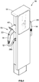
- FIG. 1 illustrates an electric vehicle charging station (EVCS) or electric vehicle supply equipment (EVSE) 10 that includes a pedestal or housing 11 connected to an electrical power source 20 such as the local electric utility grid or a generator or a photovoltaic (PV) array, or any other source of electrical power, or any combination of the foregoing.
- the electrical power source 20 can refer to the connections from the EVCS 10 to the utility grid, generator, or PV array.
- the utility grid, generator, or PV array itself would not be part of the EVCS 10, but rather the EVCS 10 includes conventional connections to power conductors that eventually lead to the actual source of energy (e.g., a utility grid, a generator, or a PV array).
- the terms EVCS and EVSE are used synonymously and interchangeably herein.
- the power train of an electric vehicle is primarily powered by an electric motor that draws power from a rechargeable energy storage device such as a battery, as well as exchanging information.
- the electric vehicle typically has an electrical receptacle for receiving an electrical connector coupled to an electrical power supply for charging one or more batteries in the vehicle.
- the term "electric vehicle” includes both vehicles that use only electrical power and hybrid vehicles in which the power train uses both an electrical power source 20 and an internal combustion engine.
- a pedestal-style EVCS 10 is shown in FIG. 1 , the present disclosure is not limited to any particular form factor of the EVCS.
- the electrical power source 20 is connected to one end of a power cable 12 via conventional safety devices such as a circuit breaker or fuse.
- the other end of the power cable 12 is connected to an electrical connector contained within a handle 14.
- the EVSE connector 13 includes multiple electrical terminals adapted to engage mating electrical terminals in a conventional electrical receptacle that is standard equipment in electric vehicles.
- the current standard for electrical connectors for charging electric vehicles in North America is the SAE J1772 standard, for both the male and female electrical terminals used to connect the battery in an electric vehicle to an EVCS to recharge the vehicle's rechargeable battery (which can include one or more batteries, but for convenience, the vehicle's battery shall be referred to herein in the singular form).
- a J1772 connector includes three conductors for connecting the power carrying lines of the electrical power source 20 to the vehicle's charging electronics and to an electric vehicle ground terminal. The vehicle then receives and stores electrical power in its battery for future use by the vehicle.
- the power cable 12 can have a length of 25 feet or shorter, as specified by Article 625 of the National Electrical Code (NEC) in the United States, or any other length within a limit set by an applicable standards body or regulatory authority.
- NEC National Electrical Code
- the handle 14 When the charging station 10 is not in use, the handle 14 is inserted into a docking station 15 on the pedestal 11.
- the docking station 15 is located at a preselected elevation on the pedestal 11 that is convenient for all users of the charging station 10.
- the docking station 15 does not include any electrical connectors, but provides physical support and protection for the EVSE connector 13 when it is not in use.
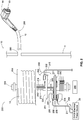
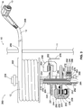
- FIG. 2 illustrates a cable reel assembly 200 housed within the pedestal 11 of the EVCS 10.
- the cable reel assembly includes the cable 12, which is electrically connected to an EVSE connector 13 at one end 208 of the cable 12, and a reel or a drum 202 around which the cable 12 is wound (or spooled or retracted) or unwound (or unspooled or dispensed).
- the reference number 202 will be referred to herein as a reel, although it can just as equally be a drum or any other suitable structure around which an electrical cable can be wound.
- the reel 202 is rotatable in two opposing directions (e.g., clockwise versus anti-clockwise).
- the reel 202 is supported by a shaft 204 and is rotated in one direction or another by a mechanism 206, which can be any conventional mechanical or electro-mechanical mechanism suitable for rotating the reel 202 in two opposing directions.
- the mechanism 206 can be a bidirectional motor mechanically coupled to the shaft 204, which turns the shaft 204 in one direction or another under the electric power of the motor.
- the mechanism 206 can include one or more springs or other biasing mechanisms, for example, to mechanically rotate the shaft 204 in one direction or its opposite.
- the reel 202 can be rotated in two opposing directions to allow the cable 12 to be wound or spooled around the reel 202 in a first direction (e.g., clockwise) or unwound or dispensed from the reel 202 in a second direction opposite from the first direction (e.g., anti-clockwise).
- first direction e.g., clockwise
- second direction opposite from the first direction (e.g., anti-clockwise).
- the first conductor 210 can be made, for example, of copper, and can have a gauge sufficient to carry SAE Level 1 (e.g., 120V at 16A) or SAE Level 2 (e.g., 240V at 30A or 80A) current or any higher level of current, such as in the proposed (at the time of filing of the present disclosure) SAE Level 3 charging limits (e.g., 400A or 240kW).
- SAE Level 1 e.g., 120V at 16A
- SAE Level 2 e.g., 240V at 30A or 80A
- SAE Level 3 charging limits e.g. 400A or 240kW.
- a first conductive member 220 is electrically connected to the first conductor 210 at the other end of the cable 12 inside the pedestal 11.
- the first conductive member 220 can be carried by a rotor 221 so that both move simultaneously with the rotation of the reel 202.
- the first conductive member 220 can be an electrically conductive disc or drum, and for convenience, the first conductive member 220 may be referred to herein as a first disc 220, without intending to limit the form factor of the first conductive member 220 to a disc or drum.
- the first conductive member 220 can be any electrically conductive structure.
- the terms "electrically conductive” and “electrically conducting” are synonymous herein, referring to any structure capable of carrying electrical current.
- the first conductor 210 can be connected, for example, to an L1 terminal or pin 1 of the J1772 connector 13, as defined by the SAE J1772 Standard.
- the conductors 210, 212 are configured to carry a high current, whereas the data conductors 280, 282, 284 discussed below are configured to carry low-current data signals or ground.
- the cable reel assembly 200 further includes a first caliper assembly 230 having a closed position in which a first conductive pad 232 of the first caliber assembly 230 is clamped onto the first conductive member 220, thereby electrically coupling the first conductive member 220 to the EVCS 10 (and thereby to the electrical power source 20 for the EVCS 10) and preventing the cable 12 from being unwound from the reel 202.
- the first conductive pad 232 is coupled to a clamp 234 of the first caliper assembly 230.
- the first caliper assembly 230 also has an open position in which the first conductive pad 232 is unclamped from the first conductive member 220 thereby decoupling the first conductive member 220 from the EVCS 10 (and thereby from the electrical power source 20) and freeing the cable 12 to be wound around or unwound from the reel 202.
- the first caliper assembly 230 can be operated between its open and closed positions.
- first or hydraulic or electro-hydraulic systems can be used to actuate the jaws of the first clamp 234 to clamp down upon the first rotor 220 and to be released from physical contact with the first rotor 220 and thereby break any electrical connection between the first clamp 234 and the first conductive member 220.
- first, second, third, and so forth as used herein are not intended to convey any relative importance, rank, temporal sequence, or order, but are intended merely to differentiate two like components from one another.
- first caliper assembly 230 when the first caliper assembly 230 is clamped onto the first conductive member 220, there can be an additional protection device, such as a relay or a contactor in the EVCS 10, which is operated in cooperation with the actuation of the first caliper assembly 230 to control the flow of current through the first conductor 210 to the cable 12.
- a relay or other switch can be actuated to allow current to flow from the electrical power source 20 to the first conductor 210.
- a protection device such as a contactor can be actuated to stop the current from flowing from the electrical power source 20 to the first conductive pad 232.
- the present disclosure does not necessarily require a protection device such as a switch or a contactor, and the electrical connections between the electrical power source 20 and the first conductor 210 can be made or broken directly through actuation of the first caliper assembly 230.
- An internal conductor 211 is electrically coupled directly or through a protection device to the electrical power source 20 for the EVCS 10.
- the basic configuration is applicable to any apparatus in an electrical distribution system in which it is desirable or necessary that the apparatus be disconnected from the main power source while the cable 12 is being dispensed or retracted from the reel 202.
- additional components that can be optionally added according to different configurations as enhancements to the basic configuration just described.
- the present disclosure contemplates the basic configuration alone or in any combination with of any one or more of these additional optional components that will be described next.
- the cable reel assembly 200 can further include a second conductive member 222 electrically connected to a second conductor 212 of the cable 12 at the other end (opposite the first end 208) of the cable 12.
- the second conductor 212 can be connected to an L2 terminal or pin 2 of the J1772 connector 13 as defined by the SAE J1772 Standard.
- This second conductor 212 can carry neutral (in the case of L1 charging) or additional current to support SAE Level 2 charging.
- the second conductive member 222 here shown as a disc, is carried by the same rotor 221 as the first conductive member 220.
- the first caliper assembly 230 includes a second conductive pad 236 that is clamped onto the second conductive member 222 in the closed position thereby electrically coupling the second conductive member 222 to the EVCS 10 (and eventually to the electrical power source 20) and unclamped from the second conductive member 222 in the open position thereby decoupling the second conductive member 222 from the EVCS 10 (and thereby from the electrical power source 20).
- the first conductor 210 connects to an L1 terminal of the EVSE connector 13, and the second conductor 212 connects to an L2 or neutral terminal of the EVSE connector 13.
- the first conductive member 220 (or first disc) rotates with the shaft 204 of the reel 202 as the cable is retracted or dispensed from the reel 202.
- a collar or sleeve 242 ( FIG. 2 ) attached to the shaft 204 supports the first conductive member 220 via the rotor 221 so that the first conductive member 220 rotates with the shaft 204.
- the second conductive member 222 can be an electrically conductive disc (best seen in FIG.
- the second conductive member 222 which is attached to the same rotor 221 as the first conductive member 220, rotates with the shaft 204 by way of the collar 242, to which the rotor 221 is attached.
- the first and second conductors 210, 212 extend away from the reel 202 and along an exterior of the shaft 204 to the first and second conductive members 220, 222, respectively.
- the conductors 210, 212 run along the outside of the shaft 204 away from the reel 202 to the conductive members 220, 222.
- the conductors 210, 212 are shown as being external to the shaft 204, alternately, they can run down an inner hollow center or bore of the shaft 204.
- the shaft 204 provides shielding for the low-current data signal conductors 280, 282, 284 (which are themselves insulated), discussed below, running inside the shaft 204 from the electromagnetic interference that can be produced by the power conductors 210, 212.
- the two sets of conductors can be shielded from one another. This also simplifies assembly of the cable reel assembly 200 and reduces the possibility of accidentally connecting a power conductor to a data signal terminal or vice versa.
- the cable reel assembly 200 can further include a third conductive member 224 electrically connected to a third conductor 214 at the other end of the cable 12.
- the third conductor 214 can run along an exterior of the shaft 204 away from the reel 202 to the third conductive member 224, which can also be an electrically conductive disc (best seen in FIG. 4 ).
- the conductive members 220, 222, 224 are circular, hole-bearing discs, these conveniently include a central hole through which the conductors 210, 212, 214 can run without getting twisted around the shaft 204 as the reel 202 rotates.
- the cable reel assembly 200 includes a second caliper assembly 250 having a closed position in which a third conductive pad 252 that is clamped onto the third conductive member 224 thereby electrically coupling the third conductive member 224 to the EVCS 10 (and thereby to the electrical power source 20) and preventing the cable 12 from being unwound from the reel 202.
- the second caliper assembly 250 like the first caliper assembly 230, also has an open position in which the third conductive pad 252 is unclamped from the third conductive member 224 by a second clamp 254 thereby decoupling the third conductive member 224 from the EVCS 10 (and thereby to the electrical power source 20).
- the third conductive member 224 can be carried by a second rotor 251, like the rotor 221 carries the first and second conductive members 220, 222.
- the second rotor 251 can be attached to or integrated with a collar or sleeve 244 that is attached to the shaft 204 and rotates with the shaft 204.
- the collars 242, 244 also operate to maintain the disc 224, which can be connected to a ground potential, a fixed distance away from the discs 220, 222, which can be energized, thereby reducing the risk of an internal ground fault connection inside the EVCS 10, even in the case of a mechanical failure of the caliper assemblies 230, 250, the discs 220, 222, 224, or the rotors 221, 251.
- the third conductor 214 connects to a ground terminal of the EVSE connector 13 through the cable 12.
- the third conductive pad 252 is connected inside the housing 11 to a ground conductor 215 that is connected to a ground potential.
- the pads 232, 236, 252 are electrically conductive, and these pads make the initial physical contact with the corresponding discs 220, 222, 224; however, as discussed below, these pads can also be made of a non-electrically conductive material such that the initial physical contact between the pads and the discs 220, 222, 224 is nonconducting. Then, after the initial physical contact is made, the pads 232, 236, 252 have an electrically conductive portion or pad that makes the electrical connection between the discs 220, 222, 224 and the power conductors 210, 212, 214.
- the second caliper assembly 250 can be activated to stop the reel 202 from moving, thereby mechanically arresting the cable 12 from being retracted or dispensed from the EVCS 10 without connecting the L1 and L2 terminals of the EVCS connector 13 to the EVCS 10 and thereby avoiding any line voltages being exposed at the connector 13.
- the connection and disconnection of the power conductors relative to the electrical power source 20 can be timed and coordinated with the actuation of the contactor. For example, mechanical stoppage of the reel 202 can occur before the contactor switch is closed to allow current flow to the cable 12, and then the ground connection can be established first, followed by the power connections, or vice versa.
- a contactor can be used to make or break the electrical connections between the power conductors 210, 212 and the electrical power source 20, whereas the caliper assemblies 230, 250 are used for mechanical braking or locking and releasing of the reel 202.
- the caliper assemblies 230, 250 also operate to establish an electrical continuity from the power conductors 210, 212 in the cable 12 to the conductors 211, 213 that lead to the contactor of the EVCS 10. In all cases, mechanical lockage of the reel 202 can be required before any electrical connection is established between the EVCS connector 13 and the electrical power source 20 for the EVCS 10.
- a slip ring and rotating contact can be used instead to maintain a constant ground connection, such that the ground terminal of the connector 13 always has a ground connection (regardless of the open or closed state of the first caliper assembly 230) to allow the proximity and control pilot signals to be used when current is not flowing through the power conductors 210, 212.
- the L1/L2 current, neutral and ground connections are merely exemplary, and those skilled in the art will readily appreciate that the first, second, and third conductors 210, 212, 214 can carry any combination of L1/L2 current, neutral, and ground instead of the specific examples described.
- the first conductor 210 can be connected to ground instead of to the L1 terminal of the EVSE connector 13. Fewer or additional power conductors are contemplated depending on the application.
- the EVSE application is just one exemplary application disclosed herein, but the present disclosure is not limited to EVSE applications.
- Data signals in this context refer to the control pilot and proximity detection signals, as well as the ground signal that is specified in the SAE J1772 Standard and similar standards or specifications for charging electric vehicles.
- the proximity detection signal is used to ensure that the electric vehicle cannot be driven away while the cable 12 is attached.
- the control pilot signal is used to adjust a charge rate of the battery in the electric vehicle. Additional data signals are also contemplated, whether they are part of the SAE J1772 Standard or not, as the present disclosure is not limited to the described data signals.
- the cable reel assembly 200 can include a first slip ring 262 that encircles and rotates with a hollow shaft 204 of the reel 202.
- the slip ring 262 rotates with the shaft 204 and maintains a constant and continuous electrical (and physical) contact with a first conductive contact 272, which abuts against the first slip ring 262.
- the first conductive contact 272 is electrically connected to a first signal conductor 280 that extends inside the hollow shaft 204 of the reel 202 to the cable 12.
- the first signal conductor 280 connects to a control pilot terminal or a proximity terminal or a ground terminal of the EVSE connector 13.
- the first signal conductor 280 is electrically coupled to the first conductive contact 272 via the first slip ring 262 regardless of (i.e., independent from) whether the first caliper assembly 230 is in the closed position or in the open position.
- the cable reel assembly 200 can include a second slip ring 264 that encircles and rotates with the hollow shaft 204 and a second conductive contact 274, which abuts the second slip ring 264 and is electrically connected to a second signal conductor 282 that extends inside the hollow shaft 204 with the first signal conductor 280 to the cable 12.
- the second signal conductor 282 connects to another of the control pilot terminal or the proximity terminal or the ground terminal of the EVSE connector 13 (e.g., a terminal different from the terminal to which the first signal conductor 280 is connected).
- the second signal conductor 282 is electrically coupled to the second conductive contact 274 via the second slip ring 264 regardless of whether the first caliper assembly 230 is in the closed position or in the open position.
- the cable reel assembly 200 can further include a third slip ring 266 that encircles and rotates with the hollow shaft 204 and a third conductive contact 276, which abuts the third slip ring 266 and is electrically connected to a third signal conductor 284 that extends inside the hollow shaft 204 with the first and second signal conductors 280, 282 to the cable 12.
- the third signal conductor 284 connects to the last of the control pilot terminal or the proximity terminal or the ground terminal of the EVSE connector 13 (i.e., whichever remaining terminal that is not connected to either the first or second signal conductors 280, 282) regardless of whether the first caliper assembly 230 is in the closed position or in the open position.
- the J1772 connector 13 has five terminals, but six conductors are shown in FIG. 2 , two of which can be ground. Note that one ground conductor can be used in an alternate aspect. However, when two conductors are used for ground (one always connected to ground, while the other one is selectively connectable to ground), the internal connection to the ground terminal in the connector 13 can be made within the cable 12 (not shown). Those skilled in the art will readily appreciate that there are many ways to connect the two ground conductors to one another, and such details are not pertinent to an understanding of the concepts disclosed herein.
- the first, second, and third conductive contacts 272, 274, 276 are connected, such as by electrical terminal blocks or any other suitable connector, to corresponding data conductors 292, 294, 296, one, some, or all of which are connected to control electronics (not shown) of the EVCS 10 for processing the control pilot and/or proximity signals.
- the housing 11 of the EVCS pedestal encloses the entire cable reel assembly 200, including the first and second caliper assemblies 230, 250, and a majority of the cable 12 when it is fully wound around the reel 202.
- the cable 12 passes through an opening 290 in the housing 11 as the cable 12 is retracted into the housing 11 or dispensed from the housing 11.
- the cable reel assembly 200 is shown generally inside the housing 11, a further enclosure within the housing 11 can enclose part or all of the cable reel assembly 200 within the EVCS 10.
- the main point here is that the cable reel assembly 200 is housed somewhere inside the confines of the housing 11 of the EVCS 10. Only the cable 12 protrudes through the opening 290 of the housing 11 to an area outside of the housing 11.
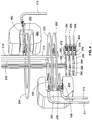
- FIG. 4 illustrates part of a disembodied cable reel assembly 200 shown in FIGS. 2-3 , in which the housing 11, the reel 202, the shaft 204, the rotors 221, 251, the collars 242, 244, and other structures have been removed for ease of illustration to reveal the electrical connections from the conductors to the mechanical elements involved in the cable reel assembly 200.
- the first clamp 234 is shown in which the conductor 211 (which is coupled to the electrical power source 20 for the EVCS 10) is connected to the pad 232 by a flat terminal 432.
- the conductor 213 is connected to the pad 236 by a flat terminal 436.
- the conductor 215 (e.g., connected to a ground potential) is connected to the pad 252 of the second clamp 254 by a flat terminal 452.
- the flat terminals 432, 452 extend away from the clamps 234, 254 to accommodate the bending radius of the internal conductors 211, 213, 215 and to simplify the connection during assembly of the cable reel assembly 200 of the conductors 211, 213, 215 to the corresponding terminals 432, 436, 452.
- any number of structures can be provided between the corresponding open jaws of the clamps 234, 252.
- the examples shown in the illustrations are just one of many ways of protecting the clamps 234, 254 and discs 220, 222, 224 from abrasion or warping as they endure repeated friction contact over time.
- Any of the structures of the clamps 234, 254 that make physical contact with the respective discs 220, 222, 224 can be made of any electrically conductive or non-electrically conductive material, and because the clamps 234, 254 in these illustrations have a jaw that can carry two electrical conductors per clamp, up to four different electrical conductors can be brought to up to four discs for mechanical stoppage.
- a single clamp can be used instead, having multiple jaws that move simultaneously with one another, to support more than two electrical conductors.
- a separate clamp need not be used; rather a single clamp with multiple jaws that move simultaneously can be used instead.
- Each of the multiple jaws can connect up to two conductors to the discs.
- the cable reel assemblies disclosed herein can be used in any electrical distribution system in which it is desirable to have a retractable cable in which power is unavailable during cable retraction or dispensation and which mechanically prevents the cable retraction or dispensation to allow electrical current to flow through the cable to a load.
- a feature of the cable reel assemblies disclosed herein is that no current flows through the power conductors in the cable when the cable is being retracted or dispensed from its housing.
- mechanical stoppage of the reel is the minimum that is required to allow current flow through the power conductors in the cable.
- the cable can be stopped at any arbitrary position to allow any length of the cable to be dispensed from the housing. Moreover, the cable can be rotated around a reel in two opposing directions, and can be stopped in either direction at any position. Alternately or additionally, a control signal can be required, such as via a human-machine interface on a connector attached to the cable, to allow current flow following mechanical stoppage of the reel. Another optional feature is that other conductors, such as those carrying data/control signals, can always be energized even as the cable is being retracted or dispensed from the housing of the cable reel assembly.
- the proximity signal from the connector 13 can be used to control the release or braking of the reel 202 from the caliper assemblies 230, 250. Because the proximity signal from the connector 13 is always readable by the control electronics of the EVCS 10, this signal can be used by the control electronics to release the caliper assemblies 230, 250 upon detection of a proximity signal via a button 23 on the handle 14. When charging of the electric vehicle is complete, and the connector 13 is released from the corresponding charging receptacle in the electric vehicle, the control electronics can release the caliper assemblies 230, 250 to allow the mechanism 206 to cause the shaft 204 to rotate the reel 202 in a direction that retracts or spools the cable 12 around the reel 202.
- a drum system can be used.
- a mechanical braking or locking is achieved by pressing a shoe against a rotating drum, which also connects the power conductors to the drum or creates an electric pathway between the cable and the drum (such as in the case where a contactor is activated to allow current flow).
- a "two-stage" break or contact pad which has a non-electrically conductive (e.g., dielectric) pad, which first makes physical contact with the disc or wheel to provide mechanical braking or locking thereof, and subsequently an electrically conductive pad makes contact with the disc or wheel to allow electrical current to flow to the power conductors in the cable.
- the dielectric pad can be made of a material that offers good friction contact with the disc, such as ceramic, expanding the possibilities beyond electrically conductive materials, and minimizing or eliminating the opportunity for contact welding at the friction interfaces between the discs or drums and the pads connected to the power conductors 210, 212.
- connection strength of the caliper assemblies 230, 250 can be designed to be greater than a short circuit magnetic force to avoid a blow open of the jaws of the caliper assemblies 230, 250 in implementations where the pads 232, 236, 252 are electrically conductive and make direct friction contact with the discs 220, 222, 224.
- a separate contactor in the EVCS 10 can be used to make or break the electrical connections between the power conductors connected to the electrical power source 20 and the connector 13 of the cable 12.
- the cable reel assembly 200 can function as a "rotating contactor” that makes the physical and electrical connections from the electrical power source 20 to the power conductors 210, 212 of the cable 12.
- the cable reel assemblies shown and described herein avoid exposing line voltages at the connector 13 end of the cable 12 until the connector 13 is plugged into a corresponding electrical receptacle of an electric vehicle whereupon charging of the electric vehicle's battery is allowed to proceed under the control of the EVCS 10.
- the cable reel assembly 200 shown in FIGS. 1 and 2 can be oriented relative to earth such that the portion of the housing 11 shown is vertical (relative to earth), and the horizontally mounted reel 202 allows the cable 12 to be retracted or dispensed out of the housing 11 along a horizontal direction relative to earth.
- the portion of the housing 11 shown in FIGS. 2 and 3 refer to a vertical (relative to earth) wall of the housing 11 shown in FIG. 1 .
- the cable reel assembly 200 can be oriented in other directions, such as rotated by 90 degrees clockwise or anti-clockwise relative to its position shown in FIG. 2 .
Landscapes
- Engineering & Computer Science (AREA)
- Power Engineering (AREA)
- Transportation (AREA)
- Mechanical Engineering (AREA)
- Architecture (AREA)
- Civil Engineering (AREA)
- Structural Engineering (AREA)
- Electric Propulsion And Braking For Vehicles (AREA)
- Electric Cable Arrangement Between Relatively Moving Parts (AREA)
- Storing, Repeated Paying-Out, And Re-Storing Of Elongated Articles (AREA)
- Charge And Discharge Circuits For Batteries Or The Like (AREA)
Claims (15)
- Un ensemble formant bobine de câble (200) d'un EVSE (10), comprenant :un câble (12) électriquement connecté à un connecteur EVSE (13) au niveau d'une extrémité du câble, le câble incluant un premier conducteur (210) pour transporter un courant d'alimentation entre l'EVSE et le connecteur ;une bobine (202) autour de laquelle ou de laquelle le câble est enroulé ou déroulé ;un premier élément conducteur (220) électriquement connecté au premier conducteur au niveau de l'autre extrémité du câble ; caractérisé en ce que l'ensemble formant bobine de câble (200) comprend en outre :
un premier ensemble formant étrier (230) ayant une position fermée dans laquelle un premier patin conducteur (232) du premier ensemble formant étrier est abloqué sur le premier élément conducteur, couplant ainsi électriquement le premier élément conducteur à l'EVSE et empêchant le câble d'être déroulé de la bobine, et une position ouverte dans laquelle le premier patin conducteur est débloqué du premier élément conducteur, découplant ainsi le premier élément conducteur de l'EVSE et libérant le câble à enrouler autour de ou à dérouler de la bobine (202). - L'ensemble formant bobine de câble (200) de la revendication 1, comprenant en outre :un deuxième élément conducteur électriquement connecté à un deuxième conducteur du câble au niveau de l'autre extrémité du câble ; etle premier ensemble formant étrier incluant un deuxième patin conducteur qui est abloqué sur le deuxième élément conducteur dans la position fermée, couplant ainsi électriquement le deuxième élément conducteur à l'EVSE, et débloqué du deuxième élément conducteur dans la position ouverte, découplant ainsi le deuxième élément conducteur de l'EVSE.
- L'ensemble formant bobine de câble de la revendication 2, où le premier conducteur se connecte à une borne L1 du connecteur EVSE et le deuxième conducteur se connecte à une borne L2 du connecteur EVSE.
- L'ensemble formant bobine de câble de la revendication 1 ou de la revendication 2, dans lequel le premier élément conducteur est un disque électriquement conducteur qui tourne avec un arbre de la bobine à mesure que le câble est enroulé autour de ou déroulé de la bobine.
- L'ensemble formant bobine de câble de la revendication 4, dans lequel le deuxième élément conducteur est un disque électriquement conducteur qui encercle l'arbre et tourne avec l'arbre de la bobine à mesure que le câble est enroulé autour de ou déroulé de la bobine.
- L'ensemble formant bobine de câble de la revendication 5, dans lequel les premier et deuxième conducteurs s'étendent en s'éloignant de la bobine et le long d'un extérieur de l'arbre jusqu'aux premier et deuxième éléments conducteurs, respectivement.
- L'ensemble formant bobine de câble de la revendication 1, comprenant en outre :un troisième élément conducteur électriquement connecté à un troisième conducteur au niveau de l'autre extrémité du câble ; etun deuxième ensemble formant étrier ayant une position fermée dans laquelle un troisième patin conducteur qui est abloqué sur le troisième élément conducteur, couplant ainsi électriquement le troisième élément conducteur à l'EVSE et empêchant le câble d'être déroulé de la bobine, et une position ouverte dans laquelle le troisième patin conducteur est débloqué du troisième élément conducteur, découplant ainsi le troisième élément conducteur de l'EVSE.
- L'ensemble formant bobine de câble de la revendication 7, où le troisième conducteur se connecte à une borne de masse du connecteur EVSE par le biais du câble et/ou où le premier conducteur est connecté à un potentiel de masse.
- L'ensemble formant bobine de câble de la revendication 1, dans lequel la bobine peut être tournée dans deux directions opposées pour permettre au câble d'être enroulé autour de la bobine dans une direction ou déroulé de la bobine dans la direction opposée.
- L'ensemble formant bobine de câble selon la revendication 1, comprenant en outre un premier anneau de coulissement qui encercle et tourne avec un arbre creux de la bobine.
- L'ensemble formant bobine de câble de la revendication 10, comprenant en outre un premier contact conducteur aboutant contre le premier anneau de coulissement et électriquement connecté à un premier conducteur de signal qui s'étend à l'intérieur de l'arbre creux de la bobine jusqu'au câble, le premier conducteur de signal se connectant à une borne pilote de commande ou une borne de proximité ou une borne de masse du connecteur EVSE, le premier conducteur de signal étant électriquement couplé au premier contact conducteur via le premier anneau de coulissement indépendamment du fait que le premier ensemble formant étrier soit dans la position fermée ou dans la position ouverte.
- L'ensemble formant bobine de câble de la revendication 11, comprenant en outre un deuxième anneau de coulissement qui encercle et tourne avec l'arbre creux, un deuxième contact conducteur aboutant contre le deuxième anneau de coulissement et électriquement connecté à un deuxième conducteur de signal qui s'étend à l'intérieur de l'arbre creux avec le premier conducteur de signal jusqu'au câble, le deuxième conducteur de signal se connectant à une autre borne parmi la borne pilote de commande ou la borne de proximité ou la borne de masse du connecteur EVSE, le deuxième conducteur de signal étant électriquement couplé au deuxième contact conducteur via le deuxième anneau de coulissement indépendamment du fait que le premier ensemble formant étrier soit dans la position fermée ou dans la position ouverte.
- L'ensemble formant bobine de câble de la revendication 12, comprenant en outre un troisième anneau de coulissement qui encercle et tourne avec l'arbre creux, un troisième contact conducteur aboutant contre le troisième anneau de coulissement et électriquement connecté à un troisième conducteur de signal qui s'étend à l'intérieur de l'arbre creux avec les premier et deuxième conducteurs de signal jusqu'au câble, le troisième conducteur de signal se connectant à la dernière borne parmi la borne pilote de commande ou la borne de proximité ou la borne de masse du connecteur EVSE indépendamment du fait que le premier ensemble formant étrier soit dans la position fermée ou dans la position ouverte.
- L'ensemble formant bobine de câble de la revendication 1, comprenant en outre un boîtier qui renferme l'ensemble formant bobine de câble, le premier ensemble formant étrier, et une majorité du câble lorsqu'il est complètement enroulé autour de la bobine, le boîtier incluant une ouverture à travers laquelle le câble est rétracté dans le boîtier ou extrait du boîtier.
- L'ensemble formant bobine de câble de la revendication 1, comprenant en outre :un arbre creux (204) connecté à la bobine (202) ;un premier anneau de coulissement (262) qui encercle et tourne avec l'arbre creux ; etun premier contact conducteur (272) aboutant contre le premier anneau de coulissement et électriquement connecté à un premier conducteur de signal (280) qui s'étend à l'intérieur de l'arbre creux de la bobine jusqu'au câble, le premier conducteur de signal se connectant à une borne pilote de commande ou une borne de proximité ou une borne de masse du connecteur EVSE.
Applications Claiming Priority (1)
| Application Number | Priority Date | Filing Date | Title |
|---|---|---|---|
| PCT/US2013/047299 WO2014209261A1 (fr) | 2013-06-24 | 2013-06-24 | Bobine de câble à verrouillage de station de charge pour véhicule électrique |
Publications (3)
| Publication Number | Publication Date |
|---|---|
| EP3014720A1 EP3014720A1 (fr) | 2016-05-04 |
| EP3014720A4 EP3014720A4 (fr) | 2017-03-22 |
| EP3014720B1 true EP3014720B1 (fr) | 2018-10-03 |
Family
ID=52142414
Family Applications (1)
| Application Number | Title | Priority Date | Filing Date |
|---|---|---|---|
| EP13887645.3A Active EP3014720B1 (fr) | 2013-06-24 | 2013-06-24 | Bobine de câble à verrouillage de station de charge pour véhicule électrique |
Country Status (4)
| Country | Link |
|---|---|
| US (1) | US9975443B2 (fr) |
| EP (1) | EP3014720B1 (fr) |
| CN (1) | CN105324896B (fr) |
| WO (1) | WO2014209261A1 (fr) |
Cited By (2)
| Publication number | Priority date | Publication date | Assignee | Title |
|---|---|---|---|---|
| GB2608589A (en) * | 2021-06-28 | 2023-01-11 | Zpn Energy Ltd | Supplying charging electricity to electric vehicles |
| LU102966B1 (de) * | 2022-06-08 | 2023-12-08 | Alexander Weimer | Vorrichtung zum Aufwickeln von Kabeln |
Families Citing this family (86)
| Publication number | Priority date | Publication date | Assignee | Title |
|---|---|---|---|---|
| US9469208B2 (en) * | 2013-03-15 | 2016-10-18 | Symbotic, LLC | Rover charging system |
| US9950634B2 (en) * | 2014-07-10 | 2018-04-24 | Control Module, Inc. | Overhead cable management for electric vehicle charging |
| US9783072B1 (en) * | 2014-12-15 | 2017-10-10 | SemaConnect Inc. | System and method for redundantly controlling a dual electric vehicle supply equipment |
| US10027148B2 (en) * | 2016-03-04 | 2018-07-17 | Ford Global Technologies, Llc | Portable electric vehicle supply equipment (EVSE) system |
| WO2017222557A1 (fr) * | 2016-06-24 | 2017-12-28 | Control Module, Inc. | <i />GESTION DE CÂBLES AÉRIENS POUR LA CHARGE D'UN VÉHICULE ÉLECTRIQUE |
| CN106314177A (zh) * | 2016-08-31 | 2017-01-11 | 苏州迈力电器有限公司 | 电源线自动收纳充电桩 |
| DE102016223715A1 (de) * | 2016-11-29 | 2018-05-30 | Whiterock Ag | Ladestation für Elektrofahrzeuge, mit wenigstens vier Lademodulen mit Ladekabeln auf Kabeltrommeln |
| WO2018119086A1 (fr) * | 2016-12-20 | 2018-06-28 | Hubbell Incorporated | Chargeur de véhicule électrique et système de gestion de câble intégré |
| CN106961497B (zh) * | 2017-03-27 | 2018-05-01 | 江苏金智酷电子科技有限公司 | 一种手机连接装置 |
| USD862383S1 (en) * | 2017-04-06 | 2019-10-08 | Webasto SE | Wallbox |
| KR101967149B1 (ko) * | 2017-04-14 | 2019-04-09 | 한국전력공사 | 충전케이블 연장 길이를 제어하는 전주에 설치된 전기차 충전 장치 및 전주에 설치된 전기차 충전 장치 제어 방법 |
| CN107662512A (zh) * | 2017-05-25 | 2018-02-06 | 广州诺绰信息技术有限公司 | 一种改进型新能源汽车充电设施 |
| USD838668S1 (en) * | 2017-06-02 | 2019-01-22 | Tesla Inc. | Electrical charging station |
| CN107253449B (zh) * | 2017-06-08 | 2018-11-06 | 安徽动力源科技有限公司 | 一种电动汽车的充电结构 |
| ES2830727T3 (es) * | 2017-10-09 | 2021-06-04 | Alpha Reel Bvba | Bobina de cable motorizada y mejorada |
| CN107738590A (zh) * | 2017-10-24 | 2018-02-27 | 浙江明烁节能科技股份有限公司 | 利用太阳能的行走式电动汽车充电站 |
| DE102018100828B4 (de) * | 2018-01-16 | 2023-07-27 | Dr. Ing. H.C. F. Porsche Aktiengesellschaft | Ladestecker für eine Ladesäule und Ladesäule mit einem solchen Stecker |
| DE102018104182A1 (de) * | 2018-02-23 | 2019-08-29 | Phoenix Contact E-Mobility Gmbh | Kabeldurchführung mit Warneinrichtung |
| US10498124B2 (en) * | 2018-02-26 | 2019-12-03 | Panasonic Intellectual Property Management Co., Ltd. | Cord reel device and electronic device |
| CN108909475B (zh) * | 2018-05-29 | 2021-01-29 | 任庆 | 一种新能源汽车充电桩 |
| US10515742B1 (en) * | 2018-05-31 | 2019-12-24 | General Electric Company | Power cable and system for delivering electrical power |
| CN109334494B (zh) * | 2018-10-16 | 2020-07-10 | 陈志君 | 一种充电桩 |
| EP3677467A1 (fr) | 2019-01-07 | 2020-07-08 | Green Motion SA | Système de repli de câbles de station de charge pour véhicules électriques |
| CN113453944B (zh) * | 2019-02-28 | 2025-02-21 | Abb电动交通有限公司 | 抵抗电弧放电和其他故障的电动车辆供电装备连接器 |
| USD903586S1 (en) * | 2019-05-07 | 2020-12-01 | Orangeq Solutions Co. | EV charger control box |
| USD902846S1 (en) * | 2019-05-07 | 2020-11-24 | Huanguang Luo | EV charger control box |
| DE102019112843B3 (de) * | 2019-05-16 | 2020-09-03 | Dr. Ing. H.C. F. Porsche Aktiengesellschaft | Kraftfahrzeugladekabel |
| DE102019209961A1 (de) * | 2019-07-05 | 2021-01-07 | Hyundai Motor Company | Ladekabel für ein elektrofahrzeug, elektrofahrzeug und verfahren zum laden eines elektrofahrzeugs |
| US11572249B2 (en) * | 2019-08-22 | 2023-02-07 | Consolidated Edison Company Of New York, Inc. | Modular cable reel |
| WO2021066386A1 (fr) * | 2019-10-04 | 2021-04-08 | 주식회사 클린일렉스 | Appareil de charge rapide pour véhicule électrique doté d'un capteur pour commander l'extraction automatique d'un câble de charge |
| USD967011S1 (en) * | 2019-10-11 | 2022-10-18 | Volta Charging, Llc | Charging station |
| USD934166S1 (en) * | 2019-10-25 | 2021-10-26 | Weidmüller Interface GmbH & Co., KG | Wallbox |
| EP3822110A1 (fr) * | 2019-11-15 | 2021-05-19 | EVBox Intelligence B.V. | Système de gestion de câble de charge |
| KR102819127B1 (ko) * | 2020-03-31 | 2025-06-12 | 주식회사 엘지에너지솔루션 | 이종금속으로 이루어진 hv 버스 바 및 이의 제조 방법 |
| CN111923767A (zh) * | 2020-08-14 | 2020-11-13 | 埃普若新能源科技(云南)有限责任公司 | 一种新能源汽车隐藏式充电系统 |
| USD934792S1 (en) * | 2020-09-04 | 2021-11-02 | Juice Technology AG | Electric vehicle charging station |
| USD935393S1 (en) * | 2020-09-04 | 2021-11-09 | Juice Technology AG | Electric vehicle charging station |
| USD970432S1 (en) * | 2020-09-04 | 2022-11-22 | Juice Technology AG | Charging station for electric vehicle |
| US12168398B2 (en) | 2020-11-09 | 2024-12-17 | Volta Charging, Llc | Systems and methods for retracting a charging cable of an electric vehicle charging station |
| US12576734B2 (en) | 2020-12-17 | 2026-03-17 | Schumacher Electric Corporation | Automotive battery power system |
| US20240092511A1 (en) * | 2021-01-04 | 2024-03-21 | Georgia Tech Research Corporation | Unmanned deployed drogue energy recovery |
| KR102331365B1 (ko) * | 2021-06-01 | 2021-12-01 | 대영채비(주) | 전기차 충전기 |
| EP4099527A1 (fr) * | 2021-06-01 | 2022-12-07 | Daeyoung Chaevi Co., Ltd. | Station de rechargement de véhicule électrique |
| US20220412023A1 (en) * | 2021-06-29 | 2022-12-29 | Beta Air, Llc | Recharging station for electric aircrafts and a method of its use |
| US11273724B1 (en) * | 2021-06-29 | 2022-03-15 | Beta Air, Llc | Recharging station for electric aircrafts and a method of its use |
| US20230158907A1 (en) * | 2021-06-29 | 2023-05-25 | Beta Air, Llc | Recharging station for electric aircrafts and a method of its use |
| DE102021118903A1 (de) * | 2021-07-21 | 2023-01-26 | Huber+Suhner Ag | Axial drehbarer Stecker |
| JP1740896S (ja) * | 2021-08-04 | 2023-04-04 | 電気自動車用充電器 | |
| CN113799633B (zh) * | 2021-09-03 | 2023-12-12 | 深圳市瀛力科技有限公司 | 一种具有保护线缆功能的新能源电桩 |
| USD1027419S1 (en) * | 2021-10-19 | 2024-05-21 | Rivian Ip Holdings, Llc | Battery charger pedestal |
| US11628746B1 (en) * | 2022-05-24 | 2023-04-18 | Beta Air, Llc | Ground service systems and devices for an electric aircraft |
| CN114194053B (zh) * | 2021-12-08 | 2023-12-19 | 国网浙江省电力有限公司浦江县供电公司 | 一种具有线缆收纳功能的新能源充电桩及其使用方法 |
| USD1092377S1 (en) * | 2022-01-11 | 2025-09-09 | Zeco Systems, Inc. | Charging station |
| USD1008950S1 (en) | 2022-01-11 | 2023-12-26 | Volta Charging, Llc | Charging station |
| USD1018447S1 (en) * | 2022-01-12 | 2024-03-19 | Parabit Systems, Inc | Charging stanchion |
| USD1017535S1 (en) | 2022-03-10 | 2024-03-12 | Parabit Systems, Inc | Charging stanchion |
| CN217320061U (zh) * | 2022-04-20 | 2022-08-30 | 东莞市盈晟智能科技有限公司 | 一种可收纳线缆的新能源汽车充电枪 |
| USD1019547S1 (en) * | 2022-04-21 | 2024-03-26 | Nanjing Powercore Tech Co., Ltd. | Charging pile with two plugs |
| USD1038870S1 (en) | 2022-05-01 | 2024-08-13 | Parabit Systems, Inc | Charging station |
| US12065059B2 (en) * | 2022-05-24 | 2024-08-20 | Beta Air, Llc | Ground service systems and devices for an electric aircraft |
| US11623535B1 (en) | 2022-05-04 | 2023-04-11 | Beta Air, Llc | Methods and systems for charging an electric aircraft including a horizontal cable arrangement |
| WO2023215447A2 (fr) * | 2022-05-04 | 2023-11-09 | Beta Air, Llc | Systeme de chargement d'un aéronef electrique a l'aide d'un enrouleur de cable |
| US20230356611A1 (en) * | 2022-05-04 | 2023-11-09 | Beta Air, Llc | System for an electric aircraft charging with a cable reel |
| US11618328B1 (en) * | 2022-05-04 | 2023-04-04 | Beta Air, Llc | Methods and systems for charging an electric aircraft including a vertical cable arrangement |
| US11623533B1 (en) | 2022-05-04 | 2023-04-11 | Beta Air, Llc | System for an electric aircraft charging with a cable reel |
| US12227097B2 (en) | 2022-05-24 | 2025-02-18 | Beta Air Llc | Electric charging station for an electric vehicle and a method for its use |
| US11654787B1 (en) | 2022-05-24 | 2023-05-23 | Beta Air, Llc | Electric charging station for an electric vehicle and a method for its use |
| US12059965B2 (en) | 2022-05-23 | 2024-08-13 | Beta Air, Llc | Systems and methods for an electric vehicle charger with a reel button for an electric vehicle |
| USD1040740S1 (en) * | 2022-07-18 | 2024-09-03 | Gary Bauer | Electric vehicle charging totem with display screen |
| USD1037143S1 (en) * | 2022-08-01 | 2024-07-30 | ENEL X Way S.r.l. | Charging station for electric vehicles |
| USD1040744S1 (en) * | 2022-08-01 | 2024-09-03 | ENEL X Way S.r.l. | Charging station for electric vehicles |
| US11685277B1 (en) * | 2022-08-18 | 2023-06-27 | Beta Air, Llc | Electric vehicle charger for an electric vehicle and a method of use |
| US20240059168A1 (en) * | 2022-08-18 | 2024-02-22 | Beta Air, Llc | Cooling system for an electric vehicle and a method of use |
| KR20240058261A (ko) * | 2022-10-26 | 2024-05-03 | 현대자동차주식회사 | 전기차 충전기의 충전 케이블 |
| USD1021777S1 (en) * | 2022-11-13 | 2024-04-09 | AUO Display Plus Corporation | Charging station |
| USD1022885S1 (en) * | 2022-11-13 | 2024-04-16 | AUO Display Plus Corporation | Charging station |
| USD1021779S1 (en) * | 2022-11-13 | 2024-04-09 | AUO Display Plus Corporation | Charging station |
| USD1021778S1 (en) * | 2022-11-13 | 2024-04-09 | AUO Display Plus Corporation | Charging station |
| USD1022884S1 (en) * | 2022-11-13 | 2024-04-16 | AUO Display Plus Corporation | Charging station |
| US20240166075A1 (en) * | 2022-11-17 | 2024-05-23 | Amazon Technologies, Inc. | Automatic inspection and locking for an electric vehicle charging station |
| USD1074583S1 (en) * | 2022-12-15 | 2025-05-13 | Autel Digital Power Co., Ltd. | Charging station for electric vehicles |
| CN115776059A (zh) * | 2023-02-15 | 2023-03-10 | 深圳汇能新能源科技有限公司 | 一种新能源汽车充电桩用高压配电箱 |
| NO348170B1 (en) * | 2023-02-21 | 2024-09-16 | Zinus As | Rotational position independent electrical coupling apparatus |
| CN117719380A (zh) * | 2024-02-08 | 2024-03-19 | 山东沃宸新能源科技有限公司 | 一种应用于地下车位的新能源汽车充电桩 |
| KR102735058B1 (ko) * | 2024-03-28 | 2024-11-27 | (주) 슬립링코리아 | 충전 케이블 릴 장치 |
| USD1118493S1 (en) | 2024-07-30 | 2026-03-17 | Parabit Systems, Inc | Outdoor wall mounted charging stanchion |
Family Cites Families (18)
| Publication number | Priority date | Publication date | Assignee | Title |
|---|---|---|---|---|
| US3180963A (en) | 1962-08-20 | 1965-04-27 | Adalet Mfg Company | High pressure contact for disconnect switch |
| US4284180A (en) * | 1980-01-21 | 1981-08-18 | Joseph Masters | Portable reel for power lines |
| US5306999A (en) | 1993-01-15 | 1994-04-26 | Hubbell Incorporated | Electric vehicle charging station |
| US6216834B1 (en) | 1997-11-25 | 2001-04-17 | Knut O. Steinhovden | Arrangements in a protection container for an electrical cable |
| JP2001167802A (ja) * | 1999-12-07 | 2001-06-22 | Toyota Autom Loom Works Ltd | 電磁誘導型非接触充電用の給電用カプラの衝撃吸収構造 |
| US6271489B1 (en) | 1999-12-31 | 2001-08-07 | Square D Company | Cam-lock enhanced pressure switch contacts |
| US6338450B1 (en) | 2000-05-08 | 2002-01-15 | Jerry Schwendinger | Cable manager for a rechargeable electric vehicle |
| EP1551086A1 (fr) | 2003-12-23 | 2005-07-06 | Reels BVBA | Tambour à câble |
| JP5062330B2 (ja) | 2008-10-09 | 2012-10-31 | トヨタ自動車株式会社 | 接続装置 |
| US9902276B2 (en) | 2009-09-25 | 2018-02-27 | Control Module, Inc. | Overhead electric vehicle charging system |
| US9457674B2 (en) | 2009-09-25 | 2016-10-04 | Control Module, Inc. | Overhead power cable management system |
| US20110169447A1 (en) * | 2010-01-11 | 2011-07-14 | Leviton Manufacturing Co., Inc. | Electric vehicle supply equipment |
| JP5182996B2 (ja) * | 2011-02-21 | 2013-04-17 | 株式会社豊田自動織機 | 車両充電装置 |
| US9102240B2 (en) * | 2011-04-25 | 2015-08-11 | Poulsen Hybrid, Llc | Charging station for electric vehicles |
| JP2013162550A (ja) * | 2012-02-01 | 2013-08-19 | Chuo Spring Co Ltd | 充電ケーブル用収容装置 |
| US9577464B2 (en) * | 2012-02-27 | 2017-02-21 | Hitachi Power Solutions Co., Ltd. | Wireless charging system |
| US9054539B2 (en) * | 2012-05-31 | 2015-06-09 | Bosch Automotive Service Solutions Inc. | Arrangement and process for housing electric vehicle supply equipment |
| JP5955702B2 (ja) * | 2012-08-27 | 2016-07-20 | 株式会社デンソー | 充電装置 |
-
2013
- 2013-06-24 CN CN201380077690.4A patent/CN105324896B/zh active Active
- 2013-06-24 US US14/898,885 patent/US9975443B2/en active Active
- 2013-06-24 WO PCT/US2013/047299 patent/WO2014209261A1/fr not_active Ceased
- 2013-06-24 EP EP13887645.3A patent/EP3014720B1/fr active Active
Non-Patent Citations (1)
| Title |
|---|
| None * |
Cited By (3)
| Publication number | Priority date | Publication date | Assignee | Title |
|---|---|---|---|---|
| GB2608589A (en) * | 2021-06-28 | 2023-01-11 | Zpn Energy Ltd | Supplying charging electricity to electric vehicles |
| GB2608589B (en) * | 2021-06-28 | 2024-07-31 | Zpn Energy Ltd | Supplying charging electricity to electric vehicles |
| LU102966B1 (de) * | 2022-06-08 | 2023-12-08 | Alexander Weimer | Vorrichtung zum Aufwickeln von Kabeln |
Also Published As
| Publication number | Publication date |
|---|---|
| EP3014720A1 (fr) | 2016-05-04 |
| US20160121747A1 (en) | 2016-05-05 |
| WO2014209261A1 (fr) | 2014-12-31 |
| CN105324896A (zh) | 2016-02-10 |
| EP3014720A4 (fr) | 2017-03-22 |
| CN105324896B (zh) | 2017-12-01 |
| US9975443B2 (en) | 2018-05-22 |
Similar Documents
| Publication | Publication Date | Title |
|---|---|---|
| EP3014720B1 (fr) | Bobine de câble à verrouillage de station de charge pour véhicule électrique | |
| US20120211319A1 (en) | Cable dispensing system | |
| EP2872355B1 (fr) | Dispositif d'annonce à distance pour équipement d'alimentation de véhicule électrique | |
| US9124097B2 (en) | Polarity correcting device | |
| KR101171070B1 (ko) | 전자기 전기 접속 장치 | |
| US20160039298A1 (en) | Charging Device for an Electric Vehicle | |
| US20150251551A1 (en) | Wall plug system for electric vehicle | |
| EP2711236A2 (fr) | Procédé et système de détection de défauts | |
| CN103796866A (zh) | 用于车辆的充电设备 | |
| WO2017007420A1 (fr) | Dispositif de distribution d'énergie électrique | |
| CN104269711A (zh) | 移动式供电装置及其集线架 | |
| JP6421466B2 (ja) | 車両の充電ケーブル | |
| EP2571094A1 (fr) | Agencement de mesure de courant sur une batterie haute tension | |
| EP2804272A1 (fr) | Unité mobile d'interconnexion électrique à haute et moyenne tension | |
| EP3677467A1 (fr) | Système de repli de câbles de station de charge pour véhicules électriques | |
| JP2011193683A (ja) | 自動車用充電ケーブル | |
| US20170222462A1 (en) | Jumper cable | |
| US20250096547A1 (en) | Electric vehicle charger cable management system | |
| CN216697982U (zh) | 临时绝缘子 | |
| CN121002737A (zh) | 高功率插接连接器系统 | |
| CN112003071A (zh) | 一种用于固定电线接头的便捷式保护装置 | |
| US11811173B2 (en) | Electrical power cord with inline ground fault circuit interrupter | |
| CN220764139U (zh) | 充放电装置 | |
| RU180027U1 (ru) | Электрический соединитель | |
| US11929637B2 (en) | Meter-based transfer switch with lockout |
Legal Events
| Date | Code | Title | Description |
|---|---|---|---|
| PUAI | Public reference made under article 153(3) epc to a published international application that has entered the european phase |
Free format text: ORIGINAL CODE: 0009012 |
|
| 17P | Request for examination filed |
Effective date: 20160114 |
|
| AK | Designated contracting states |
Kind code of ref document: A1 Designated state(s): AL AT BE BG CH CY CZ DE DK EE ES FI FR GB GR HR HU IE IS IT LI LT LU LV MC MK MT NL NO PL PT RO RS SE SI SK SM TR |
|
| AX | Request for extension of the european patent |
Extension state: BA ME |
|
| DAX | Request for extension of the european patent (deleted) | ||
| RIN1 | Information on inventor provided before grant (corrected) |
Inventor name: WHITE, MATTHEW, L. Inventor name: FILIPPENKO, KONSTANTIN, A. Inventor name: WEILER, RICHARD, K. Inventor name: JEFFERIES, KEVIN, M. Inventor name: EDWARDS, BENJAMIN, W. |
|
| A4 | Supplementary search report drawn up and despatched |
Effective date: 20170216 |
|
| RIC1 | Information provided on ipc code assigned before grant |
Ipc: H01H 3/16 20060101ALI20170210BHEP Ipc: B60L 11/18 20060101ALN20170210BHEP Ipc: H02G 11/02 20060101AFI20170210BHEP |
|
| RIC1 | Information provided on ipc code assigned before grant |
Ipc: H02G 11/02 20060101AFI20171108BHEP Ipc: H01H 3/16 20060101ALI20171108BHEP Ipc: B60L 11/18 20060101ALN20171108BHEP |
|
| RIC1 | Information provided on ipc code assigned before grant |
Ipc: H01H 3/16 20060101ALI20171207BHEP Ipc: B60L 11/18 20060101ALN20171207BHEP Ipc: H02G 11/02 20060101AFI20171207BHEP |
|
| RIC1 | Information provided on ipc code assigned before grant |
Ipc: B60L 11/18 20060101ALN20180115BHEP Ipc: H01H 3/16 20060101ALI20180115BHEP Ipc: H02G 11/02 20060101AFI20180115BHEP |
|
| RIC1 | Information provided on ipc code assigned before grant |
Ipc: H01H 3/16 20060101ALI20180124BHEP Ipc: H02G 11/02 20060101AFI20180124BHEP Ipc: B60L 11/18 20060101ALN20180124BHEP |
|
| GRAP | Despatch of communication of intention to grant a patent |
Free format text: ORIGINAL CODE: EPIDOSNIGR1 |
|
| STAA | Information on the status of an ep patent application or granted ep patent |
Free format text: STATUS: GRANT OF PATENT IS INTENDED |
|
| INTG | Intention to grant announced |
Effective date: 20180302 |
|
| RIN1 | Information on inventor provided before grant (corrected) |
Inventor name: FILIPPENKO, KONSTANTIN A. Inventor name: WHITE, MATTHEW L. Inventor name: EDWARDS, BENJAMIN W. Inventor name: JEFFERIES, KEVIN M. Inventor name: WEILER, RICHARD K. |
|
| GRAS | Grant fee paid |
Free format text: ORIGINAL CODE: EPIDOSNIGR3 |
|
| GRAJ | Information related to disapproval of communication of intention to grant by the applicant or resumption of examination proceedings by the epo deleted |
Free format text: ORIGINAL CODE: EPIDOSDIGR1 |
|
| GRAL | Information related to payment of fee for publishing/printing deleted |
Free format text: ORIGINAL CODE: EPIDOSDIGR3 |
|
| STAA | Information on the status of an ep patent application or granted ep patent |
Free format text: STATUS: REQUEST FOR EXAMINATION WAS MADE |
|
| INTC | Intention to grant announced (deleted) | ||
| GRAR | Information related to intention to grant a patent recorded |
Free format text: ORIGINAL CODE: EPIDOSNIGR71 |
|
| STAA | Information on the status of an ep patent application or granted ep patent |
Free format text: STATUS: GRANT OF PATENT IS INTENDED |
|
| GRAA | (expected) grant |
Free format text: ORIGINAL CODE: 0009210 |
|
| STAA | Information on the status of an ep patent application or granted ep patent |
Free format text: STATUS: THE PATENT HAS BEEN GRANTED |
|
| RIC1 | Information provided on ipc code assigned before grant |
Ipc: B60L 11/18 20060101ALN20180808BHEP Ipc: H02G 11/02 20060101AFI20180808BHEP Ipc: H01H 3/16 20060101ALI20180808BHEP |
|
| AK | Designated contracting states |
Kind code of ref document: B1 Designated state(s): AL AT BE BG CH CY CZ DE DK EE ES FI FR GB GR HR HU IE IS IT LI LT LU LV MC MK MT NL NO PL PT RO RS SE SI SK SM TR |
|
| INTG | Intention to grant announced |
Effective date: 20180824 |
|
| REG | Reference to a national code |
Ref country code: GB Ref legal event code: FG4D |
|
| REG | Reference to a national code |
Ref country code: CH Ref legal event code: EP Ref country code: AT Ref legal event code: REF Ref document number: 1049663 Country of ref document: AT Kind code of ref document: T Effective date: 20181015 |
|
| REG | Reference to a national code |
Ref country code: DE Ref legal event code: R096 Ref document number: 602013044682 Country of ref document: DE |
|
| REG | Reference to a national code |
Ref country code: IE Ref legal event code: FG4D |
|
| REG | Reference to a national code |
Ref country code: NL Ref legal event code: MP Effective date: 20181003 |
|
| REG | Reference to a national code |
Ref country code: LT Ref legal event code: MG4D |
|
| REG | Reference to a national code |
Ref country code: AT Ref legal event code: MK05 Ref document number: 1049663 Country of ref document: AT Kind code of ref document: T Effective date: 20181003 |
|
| PG25 | Lapsed in a contracting state [announced via postgrant information from national office to epo] |
Ref country code: NL Free format text: LAPSE BECAUSE OF FAILURE TO SUBMIT A TRANSLATION OF THE DESCRIPTION OR TO PAY THE FEE WITHIN THE PRESCRIBED TIME-LIMIT Effective date: 20181003 |
|
| PG25 | Lapsed in a contracting state [announced via postgrant information from national office to epo] |
Ref country code: FI Free format text: LAPSE BECAUSE OF FAILURE TO SUBMIT A TRANSLATION OF THE DESCRIPTION OR TO PAY THE FEE WITHIN THE PRESCRIBED TIME-LIMIT Effective date: 20181003 Ref country code: IS Free format text: LAPSE BECAUSE OF FAILURE TO SUBMIT A TRANSLATION OF THE DESCRIPTION OR TO PAY THE FEE WITHIN THE PRESCRIBED TIME-LIMIT Effective date: 20190203 Ref country code: BG Free format text: LAPSE BECAUSE OF FAILURE TO SUBMIT A TRANSLATION OF THE DESCRIPTION OR TO PAY THE FEE WITHIN THE PRESCRIBED TIME-LIMIT Effective date: 20190103 Ref country code: LT Free format text: LAPSE BECAUSE OF FAILURE TO SUBMIT A TRANSLATION OF THE DESCRIPTION OR TO PAY THE FEE WITHIN THE PRESCRIBED TIME-LIMIT Effective date: 20181003 Ref country code: LV Free format text: LAPSE BECAUSE OF FAILURE TO SUBMIT A TRANSLATION OF THE DESCRIPTION OR TO PAY THE FEE WITHIN THE PRESCRIBED TIME-LIMIT Effective date: 20181003 Ref country code: PL Free format text: LAPSE BECAUSE OF FAILURE TO SUBMIT A TRANSLATION OF THE DESCRIPTION OR TO PAY THE FEE WITHIN THE PRESCRIBED TIME-LIMIT Effective date: 20181003 Ref country code: HR Free format text: LAPSE BECAUSE OF FAILURE TO SUBMIT A TRANSLATION OF THE DESCRIPTION OR TO PAY THE FEE WITHIN THE PRESCRIBED TIME-LIMIT Effective date: 20181003 Ref country code: ES Free format text: LAPSE BECAUSE OF FAILURE TO SUBMIT A TRANSLATION OF THE DESCRIPTION OR TO PAY THE FEE WITHIN THE PRESCRIBED TIME-LIMIT Effective date: 20181003 Ref country code: CZ Free format text: LAPSE BECAUSE OF FAILURE TO SUBMIT A TRANSLATION OF THE DESCRIPTION OR TO PAY THE FEE WITHIN THE PRESCRIBED TIME-LIMIT Effective date: 20181003 Ref country code: NO Free format text: LAPSE BECAUSE OF FAILURE TO SUBMIT A TRANSLATION OF THE DESCRIPTION OR TO PAY THE FEE WITHIN THE PRESCRIBED TIME-LIMIT Effective date: 20190103 Ref country code: AT Free format text: LAPSE BECAUSE OF FAILURE TO SUBMIT A TRANSLATION OF THE DESCRIPTION OR TO PAY THE FEE WITHIN THE PRESCRIBED TIME-LIMIT Effective date: 20181003 |
|
| PG25 | Lapsed in a contracting state [announced via postgrant information from national office to epo] |
Ref country code: PT Free format text: LAPSE BECAUSE OF FAILURE TO SUBMIT A TRANSLATION OF THE DESCRIPTION OR TO PAY THE FEE WITHIN THE PRESCRIBED TIME-LIMIT Effective date: 20190203 Ref country code: GR Free format text: LAPSE BECAUSE OF FAILURE TO SUBMIT A TRANSLATION OF THE DESCRIPTION OR TO PAY THE FEE WITHIN THE PRESCRIBED TIME-LIMIT Effective date: 20190104 Ref country code: RS Free format text: LAPSE BECAUSE OF FAILURE TO SUBMIT A TRANSLATION OF THE DESCRIPTION OR TO PAY THE FEE WITHIN THE PRESCRIBED TIME-LIMIT Effective date: 20181003 Ref country code: SE Free format text: LAPSE BECAUSE OF FAILURE TO SUBMIT A TRANSLATION OF THE DESCRIPTION OR TO PAY THE FEE WITHIN THE PRESCRIBED TIME-LIMIT Effective date: 20181003 Ref country code: AL Free format text: LAPSE BECAUSE OF FAILURE TO SUBMIT A TRANSLATION OF THE DESCRIPTION OR TO PAY THE FEE WITHIN THE PRESCRIBED TIME-LIMIT Effective date: 20181003 |
|
| REG | Reference to a national code |
Ref country code: DE Ref legal event code: R097 Ref document number: 602013044682 Country of ref document: DE |
|
| PG25 | Lapsed in a contracting state [announced via postgrant information from national office to epo] |
Ref country code: DK Free format text: LAPSE BECAUSE OF FAILURE TO SUBMIT A TRANSLATION OF THE DESCRIPTION OR TO PAY THE FEE WITHIN THE PRESCRIBED TIME-LIMIT Effective date: 20181003 Ref country code: IT Free format text: LAPSE BECAUSE OF FAILURE TO SUBMIT A TRANSLATION OF THE DESCRIPTION OR TO PAY THE FEE WITHIN THE PRESCRIBED TIME-LIMIT Effective date: 20181003 |
|
| PLBE | No opposition filed within time limit |
Free format text: ORIGINAL CODE: 0009261 |
|
| STAA | Information on the status of an ep patent application or granted ep patent |
Free format text: STATUS: NO OPPOSITION FILED WITHIN TIME LIMIT |
|
| PG25 | Lapsed in a contracting state [announced via postgrant information from national office to epo] |
Ref country code: SK Free format text: LAPSE BECAUSE OF FAILURE TO SUBMIT A TRANSLATION OF THE DESCRIPTION OR TO PAY THE FEE WITHIN THE PRESCRIBED TIME-LIMIT Effective date: 20181003 Ref country code: RO Free format text: LAPSE BECAUSE OF FAILURE TO SUBMIT A TRANSLATION OF THE DESCRIPTION OR TO PAY THE FEE WITHIN THE PRESCRIBED TIME-LIMIT Effective date: 20181003 Ref country code: SM Free format text: LAPSE BECAUSE OF FAILURE TO SUBMIT A TRANSLATION OF THE DESCRIPTION OR TO PAY THE FEE WITHIN THE PRESCRIBED TIME-LIMIT Effective date: 20181003 Ref country code: EE Free format text: LAPSE BECAUSE OF FAILURE TO SUBMIT A TRANSLATION OF THE DESCRIPTION OR TO PAY THE FEE WITHIN THE PRESCRIBED TIME-LIMIT Effective date: 20181003 |
|
| 26N | No opposition filed |
Effective date: 20190704 |
|
| PG25 | Lapsed in a contracting state [announced via postgrant information from national office to epo] |
Ref country code: SI Free format text: LAPSE BECAUSE OF FAILURE TO SUBMIT A TRANSLATION OF THE DESCRIPTION OR TO PAY THE FEE WITHIN THE PRESCRIBED TIME-LIMIT Effective date: 20181003 |
|
| PG25 | Lapsed in a contracting state [announced via postgrant information from national office to epo] |
Ref country code: MC Free format text: LAPSE BECAUSE OF FAILURE TO SUBMIT A TRANSLATION OF THE DESCRIPTION OR TO PAY THE FEE WITHIN THE PRESCRIBED TIME-LIMIT Effective date: 20181003 |
|
| REG | Reference to a national code |
Ref country code: CH Ref legal event code: PL |
|
| REG | Reference to a national code |
Ref country code: BE Ref legal event code: MM Effective date: 20190630 |
|
| PG25 | Lapsed in a contracting state [announced via postgrant information from national office to epo] |
Ref country code: TR Free format text: LAPSE BECAUSE OF FAILURE TO SUBMIT A TRANSLATION OF THE DESCRIPTION OR TO PAY THE FEE WITHIN THE PRESCRIBED TIME-LIMIT Effective date: 20181003 |
|
| PG25 | Lapsed in a contracting state [announced via postgrant information from national office to epo] |
Ref country code: IE Free format text: LAPSE BECAUSE OF NON-PAYMENT OF DUE FEES Effective date: 20190624 |
|
| PG25 | Lapsed in a contracting state [announced via postgrant information from national office to epo] |
Ref country code: LU Free format text: LAPSE BECAUSE OF NON-PAYMENT OF DUE FEES Effective date: 20190624 Ref country code: LI Free format text: LAPSE BECAUSE OF NON-PAYMENT OF DUE FEES Effective date: 20190630 Ref country code: CH Free format text: LAPSE BECAUSE OF NON-PAYMENT OF DUE FEES Effective date: 20190630 Ref country code: BE Free format text: LAPSE BECAUSE OF NON-PAYMENT OF DUE FEES Effective date: 20190630 |
|
| PG25 | Lapsed in a contracting state [announced via postgrant information from national office to epo] |
Ref country code: CY Free format text: LAPSE BECAUSE OF FAILURE TO SUBMIT A TRANSLATION OF THE DESCRIPTION OR TO PAY THE FEE WITHIN THE PRESCRIBED TIME-LIMIT Effective date: 20181003 |
|
| PG25 | Lapsed in a contracting state [announced via postgrant information from national office to epo] |
Ref country code: HU Free format text: LAPSE BECAUSE OF FAILURE TO SUBMIT A TRANSLATION OF THE DESCRIPTION OR TO PAY THE FEE WITHIN THE PRESCRIBED TIME-LIMIT; INVALID AB INITIO Effective date: 20130624 Ref country code: MT Free format text: LAPSE BECAUSE OF FAILURE TO SUBMIT A TRANSLATION OF THE DESCRIPTION OR TO PAY THE FEE WITHIN THE PRESCRIBED TIME-LIMIT Effective date: 20181003 |
|
| PG25 | Lapsed in a contracting state [announced via postgrant information from national office to epo] |
Ref country code: MK Free format text: LAPSE BECAUSE OF FAILURE TO SUBMIT A TRANSLATION OF THE DESCRIPTION OR TO PAY THE FEE WITHIN THE PRESCRIBED TIME-LIMIT Effective date: 20181003 |
|
| PGFP | Annual fee paid to national office [announced via postgrant information from national office to epo] |
Ref country code: DE Payment date: 20250626 Year of fee payment: 13 |
|
| PGFP | Annual fee paid to national office [announced via postgrant information from national office to epo] |
Ref country code: GB Payment date: 20250617 Year of fee payment: 13 |
|
| PGFP | Annual fee paid to national office [announced via postgrant information from national office to epo] |
Ref country code: FR Payment date: 20250624 Year of fee payment: 13 |