EP3014927B1 - Sélection de tête de grappe dans un réseau de communications - Google Patents
Sélection de tête de grappe dans un réseau de communications Download PDFInfo
- Publication number
- EP3014927B1 EP3014927B1 EP13888202.2A EP13888202A EP3014927B1 EP 3014927 B1 EP3014927 B1 EP 3014927B1 EP 13888202 A EP13888202 A EP 13888202A EP 3014927 B1 EP3014927 B1 EP 3014927B1
- Authority
- EP
- European Patent Office
- Prior art keywords
- cluster head
- wireless device
- metric
- beacon signal
- received
- Prior art date
- Legal status (The legal status is an assumption and is not a legal conclusion. Google has not performed a legal analysis and makes no representation as to the accuracy of the status listed.)
- Active
Links
Images
Classifications
-
- H—ELECTRICITY
- H04—ELECTRIC COMMUNICATION TECHNIQUE
- H04W—WIRELESS COMMUNICATION NETWORKS
- H04W76/00—Connection management
- H04W76/10—Connection setup
- H04W76/14—Direct-mode setup
-
- H—ELECTRICITY
- H04—ELECTRIC COMMUNICATION TECHNIQUE
- H04W—WIRELESS COMMUNICATION NETWORKS
- H04W84/00—Network topologies
- H04W84/18—Self-organising networks, e.g. ad-hoc networks or sensor networks
- H04W84/20—Leader-follower arrangements
-
- H—ELECTRICITY
- H04—ELECTRIC COMMUNICATION TECHNIQUE
- H04L—TRANSMISSION OF DIGITAL INFORMATION, e.g. TELEGRAPHIC COMMUNICATION
- H04L45/00—Routing or path finding of packets in data switching networks
- H04L45/46—Cluster building
-
- H—ELECTRICITY
- H04—ELECTRIC COMMUNICATION TECHNIQUE
- H04W—WIRELESS COMMUNICATION NETWORKS
- H04W16/00—Network planning, e.g. coverage or traffic planning tools; Network deployment, e.g. resource partitioning or cells structures
- H04W16/24—Cell structures
- H04W16/28—Cell structures using beam steering
-
- H—ELECTRICITY
- H04—ELECTRIC COMMUNICATION TECHNIQUE
- H04W—WIRELESS COMMUNICATION NETWORKS
- H04W40/00—Communication routing or communication path finding
- H04W40/24—Connectivity information management, e.g. connectivity discovery or connectivity update
- H04W40/32—Connectivity information management, e.g. connectivity discovery or connectivity update for defining a routing cluster membership
-
- H—ELECTRICITY
- H04—ELECTRIC COMMUNICATION TECHNIQUE
- H04W—WIRELESS COMMUNICATION NETWORKS
- H04W56/00—Synchronisation arrangements
- H04W56/001—Synchronization between nodes
-
- H—ELECTRICITY
- H04—ELECTRIC COMMUNICATION TECHNIQUE
- H04W—WIRELESS COMMUNICATION NETWORKS
- H04W68/00—User notification, e.g. alerting and paging, for incoming communication, change of service or the like
- H04W68/005—Transmission of information for alerting of incoming communication
-
- H—ELECTRICITY
- H04—ELECTRIC COMMUNICATION TECHNIQUE
- H04W—WIRELESS COMMUNICATION NETWORKS
- H04W72/00—Local resource management
- H04W72/50—Allocation or scheduling criteria for wireless resources
- H04W72/54—Allocation or scheduling criteria for wireless resources based on quality criteria
- H04W72/541—Allocation or scheduling criteria for wireless resources based on quality criteria using the level of interference
-
- H—ELECTRICITY
- H04—ELECTRIC COMMUNICATION TECHNIQUE
- H04W—WIRELESS COMMUNICATION NETWORKS
- H04W72/00—Local resource management
- H04W72/50—Allocation or scheduling criteria for wireless resources
- H04W72/56—Allocation or scheduling criteria for wireless resources based on priority criteria
- H04W72/563—Allocation or scheduling criteria for wireless resources based on priority criteria of the wireless resources
Definitions
- Embodiments presented herein relate to communications network, and particularly to a method, a wireless device and a computer program for cluster head selection in a communications network.
- NW 3GPP LTE networks
- D2D Device to Device communication
- ProSe Proximity Services
- the cellular network including the eNB can get damaged or become partially or completely dysfunctional due to a disaster or emergency situation.
- UEs should still be able to communicate as long as they are in the coverage area of each other or can reach each other via several D2D hops.
- Device discovery is a well known and widely used component of many existing wireless technologies, including ad hoc and cellular networks.
- beacon signals examples include Bluetooth, several variants of the IEEE 802.11 standards suite such as WiFi Direct, and Flashlinq.
- One mechanism used by these standards is to use specially designed beacon signals that devices broadcast so that nearby devices can detect the proximity of such beacon broadcasting devices.
- beacon signals also allow nearby devices to detect the identity and some characteristics of the broadcasting device.
- Receiving devices can also use the beacon signal to estimate the channel and/or path loss to the beacon broadcasting device.
- a CH node can be compared to a small range base station that, - in the absence of a cellular eNB - provides (a subset of and) similar functionality as an eNB.
- a CH node can provide synchronization and radio resource management within its cluster and also act as a central node to create a tree topology for communication with the cluster.
- the CH can also provide a relaying functionality towards other clusters or towards a cellular eNB.
- clustering and cluster head based integrated ad hoc and cellular communications can meet the basic requirement on managing direct D2D communications even in the absence of the cellular NW, one technical aspect is the selection of the cluster head nodes.
- cluster head selection One typical way to establish cluster head selection is that a given device self-nominates as cluster head and then announces itself as the cluster head. This self-nomination is based on randomness or using some other criteria. Since several devices within the proximity of each other may self-nominate as cluster heads, a mutual negotiation is typically necessary in order for one of them to remain as the single cluster head.
- EP1978689 there is disclosed a method for cluster head selection in an ad-hoc network.
- a token is created by each node in a given selection process.
- the tokens are circulated between the nodes in the ad-hoc network.
- a node receives a token it compares it to a token stored in the node.
- the stored token represents the best token received by the node so far. If the received token is better than the stored token it replaces the stored token in the memory of the node and the received token is also forwarded to another node in the ad-hoc network. However, if the received token is not better than the stored token it is ignored.
- the best token will be recorded in all the nodes and the node associated with the best token becomes cluster head.
- US 2007/299950 A1 discloses a system for creating optimally-sized clusters.
- US 2010/046363 A1 discloses methods for managing an election of a cluster head in ad hoc mobile communication network and systems thereof.
- KULKARNI AB ET AL "Engineering Self-Critical Behavior in Mobile Adhoc Networks", MILCOM 2006 : WASHINGTON, DC, PISCATAWAY, NJ : IEEE OPERATIONS CENTER, US, 23 October 2006 (2006-10-23), pages 1-7, ISBN: 978-1-4244-0617-3 , discloses the application of the theory of self-criticality to the problem of self-organization in mobile ad hoc networks.
- WO 2009/018212 discloses distributed ad hoc network protocol using synchronous shared beacon signaling.
- An object of embodiments herein is to provide improved cluster head selection in a communications network.
- the inventors of the enclosed embodiments have realized that one issue for a cluster based communications network is how to select which devices that should act as cluster heads. Specifically when multiple devices enter the proximity of each other, how they organize themselves into one or several clusters, and how one or several cluster head(s) are selected.
- the inventors of the enclosed embodiments have further realized that it may be beneficial to ensure that the different devices have a common understanding of which devices act as cluster heads and which devices are cluster members belonging to the same cluster. As herein defined, the "common understanding" among devices is generally referred to as the integrity of the cluster and the roles of the devices in the cluster.
- An object of embodiments herein is therefore to provide a cluster head selection whereby partially dysfunctional network nodes and UEs can form clusters. For example, if a cellular base station can no longer provide access to core network services but can still provide synchronization signals, then UEs should be able to take advantage of such synchronization signals even when not accessing core network services.
- a particular object is therefore to provide improved cluster head selection in a communications network without being dependent on mutual negotiation.
- a method for cluster head selection in a communications network is performed by a wireless device.
- the method comprises receiving a respective beacon signal from each one of at least one further wireless device, each beacon signal comprising a cluster head capability metric.
- the method comprises comparing each of the received cluster head capability metrics to at least one qualifying criterion.
- the method comprises selecting one of the at least one further wireless devices as the cluster head of the wireless device based on the comparison.
- each device since each device, based on a few rules, performs a local selection of which peer device that shall act as its cluster head the selection criterion is simple to implement and the quality and uniformity of independent implementations can therefore be assured.
- cluster head may in a similar manner select a peer device as its own cluster head, interconnected clusters are automatically created, which prevents isolated clusters/devices.
- a wireless device for cluster head selection in a communications network.
- the wireless device comprises a receiver.
- the receiver is arranged to receive a respective beacon signal from each one of at least one further wireless device, each beacon signal comprising a cluster head capability metric.
- the wireless device comprises a processing unit.
- the processing unit is arranged to compare each of the received cluster head capability metrics to at least one qualifying criterion.
- the processing unit is arranged to select one of the at least one further wireless devices as the cluster head of the wireless device based on the comparison.
- a computer program for cluster head selection in a communications network comprising computer program code which, when run on a wireless device, causes the wireless device to perform a method according to the first aspect.
- a computer program product comprising a computer program according to the third aspect and a computer readable means on which the computer program is stored.
- any feature of the first, second, third and fourth aspects may be applied to any other aspect, wherever appropriate.
- any advantage of the first aspect may equally apply to the second, third, and/or fourth aspect, respectively, and vice versa.
- Other objectives, features and advantages of the enclosed embodiments will be apparent from the following detailed disclosure, from the attached dependent claims as well as from the drawings.
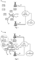
- Fig 1 shows a schematic overview of an exemplifying wireless communication system 1a.
- the wireless communication system 1a comprises network nodes 3a, 3b providing network coverage over cells (not shown). Each cell is served by at least one of the network nodes 3a, 3b.
- a wireless device (WD) 2a, 2b, positioned in a particular cell is thus provided network service by the network node 3a, 3b serving that particular cell.
- the network nodes 3a, 3b are arranged to communicate with other network nodes 3a, 3b via communications links.
- the network nodes 3a, 3b are also operatively connected to a core network 7.
- the core network 7 may provide services and data to the WD 2a, 2b operatively connected to at least one of the network nodes 3a, 3b from an external packet switched (PS) data network 8.
- PS packet switched
- the wireless communications system 1a may comprise a plurality of network nodes 3a, 3b and a plurality of WDs 2a, 2b operatively connected to at least one of the plurality of network nodes 3a, 3b.
- the communications system 1a may generally comply with any one or a combination of W-CDMA (Wideband Code Division Multiplex), LTE (Long Term Evolution), EDGE (Enhanced Data Rates for GSM Evolution, Enhanced GPRS (General Packet Radio Service)), CDMA2000 (Code Division Multiple Access 2000), WiFi, microwave radio links, etc., as long as the principles described hereinafter are applicable.
- W-CDMA Wideband Code Division Multiplex
- LTE Long Term Evolution
- EDGE Enhanced Data Rates for GSM Evolution
- Enhanced GPRS General Packet Radio Service
- CDMA2000 Code Division Multiple Access 2000
- WiFi microwave radio links
- clustering mechanisms may be deployed in the communications network 1a.
- an ad hoc network may thus be formed.
- Such mixed cellular and ad hoc networks provide a natural solution to providing communication services with partial infrastructure coverage or even in geographical areas without any cellular network coverage due to lack of infrastructure or due to natural disaster, public safety or failure situations.
- the embodiments disclosed herein relate to cluster head selection in a communications network 1a.
- a wireless device 2a, 2b In order to obtain cluster head selection in the communications network 1a there is provided a wireless device 2a, 2b, a method performed by the wireless device 2a, 2b, a computer program comprising code, for example in the form of a computer program product, that when run on the wireless device 2a, 2b causes the wireless device 2a, 2b to perform the method.
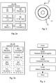
- FIG 2a schematically illustrates, in terms of a number of functional modules, the components of a wireless device 2a, 2b according to an embodiment.
- a processing unit 21 is provided using any combination of one or more of a suitable central processing unit (CPU), multiprocessor, microcontroller, digital signal processor (DSP), application specific integrated circuit (ASIC), field programmable gate arrays (FPGA) etc., capable of executing software instructions stored in a computer program product 30 (as in Fig 3 ), e.g. in the form of a memory 23.
- the processing unit 21 is thereby arranged to execute methods as herein disclosed.
- the memory 23 may also comprise persistent storage, which, for example, can be any single one or combination of magnetic memory, optical memory, solid state memory or even remotely mounted memory.
- the wireless device 2a, 2b may further comprise an input/output (I/O) interface 22 for receiving and providing information to a user interface.
- the wireless device 2a, 2b also comprises one or more transmitters 25 and receivers 24, comprising analogue and digital components and a suitable number of antennae 26 for radio communication with a network node 3 and/or with another wireless device 2a, 2b.
- the processing unit 21 controls the general operation of the wireless device 2a, 2b, e.g. by sending control signals to the transmitter 25 and/or receiver 24 and receiving reports from the transmitter 25 and/or receiver 24 of its operation.
- Other components, as well as the related functionality, of the wireless device 2a, 2b are omitted in order not to obscure the concepts presented herein.
- Fig 2b schematically illustrates, in terms of a number of functional units, the components of a wireless device 2a, 2b according to an embodiment.
- the wireless device 2a, 2b of Fig 2b comprises a number of functional units; a receiving unit 42a, a comparing unit 42b, and a selecting unit 42c.
- the wireless device 2a, 2b of Fig 2b may further comprises a number of optional functional units, such as any of a determining unit 42d, a ranking unit 42e, an adjusting unit 4f, an establishing unit 42g, and a transmit unit 42h.
- the functionality of each functional unit 42a-h will be further disclosed below in the context of which the functional units may be used.
- each functional unit 42a-h may be implemented in hardware or in software.
- the processing unit 21 may thus be arranged to from the memory 23 fetch instructions as provided by a functional unit 42a-h and to execute these instructions, thereby performing any steps as will be disclosed hereinafter.
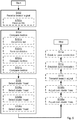
- Figs 4 and 5 are flow charts illustrating embodiments of methods of cluster head selection in a communications network.
- the methods are performed by the wireless device 2a, 2b.
- the methods are advantageously provided as computer programs 31.
- Fig 3 shows one example of a computer program product 30 comprising computer readable means 32.
- a computer program 31 can be stored, which computer program 31 can cause the processing unit 21 and thereto operatively coupled entities and devices, such as the memory 23, the I/O interface 22, the transmitter 25, the receiver 24 and/or the antennae 26 to execute methods according to embodiments described herein.
- the computer program product 31 is illustrated as an optical disc, such as a CD (compact disc) or a DVD (digital versatile disc) or a Blu-Ray disc.
- the computer program product 30 could also be embodied as a memory, such as a random access memory (RAM), a read-only memory (ROM), an erasable programmable read-only memory (EPROM), or an electrically erasable programmable read-only memory (EEPROM) and more particularly as a non-volatile storage medium of a device in an external memory such as a USB (Universal Serial Bus) memory.
- RAM random access memory
- ROM read-only memory
- EPROM erasable programmable read-only memory
- EEPROM electrically erasable programmable read-only memory
- the computer program 31 is here schematically shown as a track on the depicted optical disk, the computer program 31 can be stored in any way which is suitable for the computer program product 30.
- the computer program 31 and/or computer program product 30 may thus provide means for performing any steps as herein disclosed.
- the herein presented embodiments are based on each local wireless device selecting one of its peer wireless devices in its proximity as cluster head.
- the selection of cluster head is based on making a comparison of metrics received from the peer wireless devices.
- a method for cluster head selection in a communications network 1a, 1b as performed by a wireless device 2a comprises in a step S102 receiving a respective beacon signal 6 from each one of at least one further wireless device 2b.
- the comparison may be performed by executing functionality of the receiving unit 42a.
- the computer program 31 and/or computer program product 30 may thus provide means for receiving the respective beacon signal 6.
- a beacon signal 6 as transmitted by the wireless device 2b is schematically indicated.
- beacon signals may be transmitted by any of the wireless devices illustrated in Fig 1 .
- the beacon signals 6 are received by the receiver 24 of the wireless device 2a.
- Each beacon signal comprises a cluster head capability metric. Examples of such cluster head capability metrics will be provided below.
- selection of cluster head is based on making a comparison of metrics received from the peer wireless devices.
- the processing unit 21 of the wireless device 2a is therefore arranged to, in a step S104, compare each of the received cluster head capability metrics to at least one qualifying criterion.
- the computer program 31 and/or computer program product 30 may thus provide means for comparing each of the received cluster head capability metrics.
- the comparison may be performed by executing functionality of the comparing unit 42b. As will be further disclosed below, this decision can be based on multiple factors collected in the capability metric as transmitted in the beacon signal.
- the processing unit 21 of the wireless device 2a is then arranged to, in a step S106, select one of the at least one further wireless devices as the cluster head of the wireless device based on the comparison.
- the selection may be performed by executing functionality of the selecting unit 42c.
- the computer program 31 and/or computer program product 30 may thus provide means for selecting one of the at least one further wireless devices as the cluster head.
- This procedure may be performed individually and locally by each wireless device 2a, 2b in the communications network 1a, 1b. Which peer wireless device that is selected as cluster head for a particular wireless device 2a, 2b is thus a local decision made by each wireless device.
- a wireless device that is selected by peer wireless device(s) as a cluster head may also select a peer cluster head (in a different cluster) based on the same general principles.
- the cluster head may be a network node 3a, 3b.
- the wireless device 2a is associated with a cluster head capability metric of its own.
- the wireless device 2a may be arranged both to receive a beacon signal through its receiver 24 and to transmit a beacon signal through its transmitter 25.
- the same may also apply for other wireless devices in the wireless communication system 1a.
- the cluster head capability metric may further be based on the received beacon signal.
- the processing unit 21 of the wireless device 2a is arranged to, in an optional step S108a, adjust its own cluster head capability metric based on the received beacon signal.
- the adjusting may be performed by executing functionality of the adjusting unit 42f.
- the computer program 31 and/or computer program product 30 may thus provide means for this adjusting.
- the transmitter 25 of the wireless device 2a may then be arranged to, in an optional step S110, transmit a beacon signal comprising the adjusted cluster head capability metric.
- the transmitting may be performed by executing functionality of the transmitting unit 42h.
- the computer program 31 and/or computer program product 30 may thus provide means for this transmitting.
- the cluster head capability metric as transmitted in the beacon signal may be based on which wireless device has been selected as the cluster head.
- the processing unit 21 of the wireless device 2a is arranged to, in an optional step S108b, adjust its own cluster head capability metric based on the selected cluster head.
- the adjusting may be performed by executing functionality of the adjusting unit 42f.
- the computer program 31 and/or computer program product 30 may thus provide means for this adjusting.
- a wireless device When a wireless device has selected a peer wireless device as cluster head, it may establish a connection to this peer wireless device using existing D2D technology.
- the processing unit 21 of the wireless device 2a is arranged to, in an optional step S114 establish a peer connection to the selected cluster head.
- the establishing may be performed by executing functionality of the establishing unit 42g.
- the computer program 31 and/or computer program product 30 may thus provide means for this establishing.
- the cluster head may be selected from a ranked list of candidate cluster heads.
- the cluster head may be selected by comparing received metrics to a minimum value.
- the cluster head may be selected by comparing received metrics to the metric of the wireless device itself. Embodiments related thereto will now be described in further detail.
- the cluster head is selected from a ranked list of candidate cluster heads.
- the processing unit 21 of the wireless device 2a is arranged to, in an optional step S104a, determine a list of candidate cluster heads based on received cluster head capability metrics. The determining may be performed by executing functionality of the determining unit 42d.
- the computer program 31 and/or computer program product 30 may thus provide means for this determining. Determining a list of the candidate cluster heads according to their cluster head capability metrics may simplify the cluster head selection process. Further, the candidate cluster heads may be ranked based on their cluster head capability metrics.
- the processing unit 21 of the wireless device 2a is thus arranged to, in an optional step S104b, rank candidate cluster heads in the list based on fulfilled qualifying criteria for each received cluster head capability metrics.
- the ranking may be performed by executing functionality of the ranking unit 42e.
- the computer program 31 and/or computer program product 30 may thus provide means for this ranking.
- the cluster head may then be selected based on this ranking.
- the processing unit 21 of the wireless device 2a is thus arranged to, in an optional step S106a, select the cluster head from the list and based on the ranking.
- the selecting may be performed by executing functionality of the selecting unit 42c.
- the computer program 31 and/or computer program product 30 may thus provide means for this selecting.
- the wireless device may select as its cluster head the first wireless device in the list (i.e., the highest ranked candidate cluster head). However, if further criteria reveal that the thus selected wireless device is not suitable as cluster head, another wireless device further down the list will be selected as the cluster head. Such further criteria will be disclosed below.
- the cluster head is selected by comparing received metrics to a minimum value (as provided by means of a so-called Minimum Metric).
- Minimum Metric may be dynamically configured by a network management entity or take a value as defined in a specification.
- the processing unit 21 of the wireless device 2a is arranged to, in an optional step S104c, compare all received cluster head capability metrics to a minimum value.
- the comparing may be performed by executing functionality of the comparing unit 42b.
- the computer program 31 and/or computer program product 30 may thus provide means for this comparing.
- the minimum value may be predetermined.
- the wireless device cannot select as its cluster head a wireless device with a cluster head capability metric below the minimum value (assuming that the suitability of a wireless device is proportional to the cluster head capability metric). Thereby the number of candidate cluster heads is reduced. The cluster head is then selected from this reduced number of candidate cluster heads.
- the processing unit 21 of the wireless device 2a is thus arranged to, in an optional step S106b, select as the cluster head one of the wireless devices having a cluster head capability metrics above the minimum value.
- the selecting may be performed by executing functionality of the selecting unit 42c.
- the computer program 31 and/or computer program product 30 may thus provide means for this selecting.
- the cluster head is selected by comparing received metrics to the metric of the wireless device itself.
- the third embodiment is based on the second embodiment.
- the wireless device 2a is assumed to be associated with a cluster head capability metric of its own. This cluster head capability metric may be determined in the same way as the cluster head capability metric of the other wireless devices 2b.
- the processing unit 21 of the wireless device 2a is arranged to, in an optional step S104d, compare all received cluster head capability metrics above the minimum value to its own cluster head capability metric. That is, wireless devices with cluster head capability metrics as received in step S102 and which as in step S104b have been determined to be above the minimum value are considered as candidate cluster heads.
- the processing unit 21 of the wireless device 2a is thus arranged to, in an optional step S106c, select as the cluster head one of the wireless devices having a cluster head capability metrics above the own cluster head capability metric.
- the selecting may be performed by executing functionality of the selecting unit 42c.
- the computer program 31 and/or computer program product 30 may thus provide means for this selecting.
- the beacon signal may comprise at least one reference signal (RS).
- the beacon signal may comprise identity information.
- the beacon signal may be transmitted at certain intervals. Embodiments related thereto will now be described in further detail.
- the beacon signal is transmitted at regular intervals.
- wireless devices that need to participate in clusters may transmit a beacon signal at regular intervals.
- the transmittance of the beacon signal is event triggered.
- the beacon signal comprises an identity of the wireless device transmitting the beacon signal.
- the device identity may be a global identity, such as GUMMEI+TMSI (as described in TS 3GPP 23.003; GUMMEI is the Globally Unique MME Identity, where MME is the Mobility Management Entity, and TMSI is the Temporary Mobile Subscriber Identity). This may simplify device to device communication since the wireless devices may then directly address a message to the intended recipient.
- the receiver 24 of the wireless device 2a is arranged to, in an optional step S102a, receive at least one reference signal (RS).
- the receiving may be performed by executing functionality of the receiving unit 42a.
- the computer program 31 and/or computer program product 30 may thus provide means for this receiving.
- the at least one RS may be received from at least one other wireless device 2a or from a network node 3a, 3b.
- the RS may be used for synchronization purposes.
- the processing unit 21 of the wireless device 2a is therefore arranged to, in an optional step S112C, establish synchronization with other wireless devices 2b based on the received RS.
- the establishing may be performed by executing functionality of the establishing unit 42g.
- the computer program 31 and/or computer program product 30 may thus provide means for this establishing.
- the RS is part of the received beacon signal.
- transmittance and reception of beacon signals may be used for synchronization purposes, thereby stabilizing the clustering process.
- the capability metrics 5 may contain several fields.
- One general purpose of the capability metric is to describe how well a wireless device 2a, 2b would serve as a cluster head. This decision is made by comparing the capability metrics to at least one qualifying criterion, as in step S104. Different properties of the capability metric will now be disclosed in further detail.
- the capability metric may comprise a first field comprising a parameter relating to whether the wireless device is within network coverage of a network node 3a, 3b or not.
- the first field may thus take a value in the set ⁇ TRUE, FALSE ⁇ .
- the first field may additionally or alternatively comprise information disclosing how many hops from one wireless device to another are required before reaching a network node (such as the number of one-way or two-way peer-to-peer communications links needed to be established before a wireless device can be operatively connected to a network node).
- the capability metric may comprise a second field comprising a parameter relating to whether the wireless device can serve as a cluster head or not. This may be dependent on processing, memory, and/or battery properties of the wireless device.
- the second field may take a value in the set ⁇ TRUE, FALSE ⁇ .
- the second field may take a value in a scale, say 1-5, according to the processing, memory, and/or battery properties of the wireless device.
- the capability metric may comprise a third field comprising a parameter relating to the maximum possible transmission power of the wireless device.
- the third field may thus be integer-valued or real-valued.
- the capability metric may comprise a fourth field comprising a parameter relating to how many other wireless devices that currently have this wireless device as its cluster head.
- the fourth field may thus be integer-valued.
- the fourth field may instead of disclosing the actual number of such other devices give this number in intervals; if four intervals are used, the intervals could be defined as follows: 0, 1...10, 11...50, >51.
- the fourth field may additionally or alternatively comprise and indicator of whether or not the wireless device has capacity to act as a cluster head for a further wireless device. This could avoid unnecessary connect attempts (e.g., in the form of establishment requests) that would otherwise be rejected.
- the capability metric may comprise a fifth field disclosing identity of the current cluster head of wireless device. If the wireless device does not have a cluster head, this field may be empty or take a null-value.
- the capability metric may comprise a sixth field disclosing a random number.
- the random number may be generated locally by the wireless device.
- the random number may for example be a uniformly distributed number from 0-255.
- the random number may be used as a deciding parameter if all other capability metrics of two wireless devices are equal. This will be further explained below.
- the capability metric may comprise fewer or further fields than the fields disclosed above. Further fields may provide further information which may be considered during the cluster head selection process
- the cluster head capability metric thus represents at least one of the number of wireless devices currently having selected the wireless device as their cluster head, a network coverage parameter of the wireless device, capability of the wireless device serving as a cluster head, identity of the current cluster head of wireless device, and a random number.
- a metric comparison function may be used to compare values of two or more cluster head capability metrics.
- the metric comparison function may be defined in several ways. According to one embodiment the metric comparison function has two inputs; Metric-i representing a first cluster head capability metric (from one wireless device) and Metric-2 representing a second cluster head capability metric (from another wireless device). The output of the metric comparison function may then take one of three values:
- Each field of Metric-1 may thus be compared with the corresponding field of Metric-2. Examples of fields have been disclosed above.
- relation operators (such as greater than, equal to, and less than) may be defined for BOOLEAN; INTEGER and REAL types - depending on the types of the fields of the metrics. The output of this comparison may then, for each compared field, take one of the above three values, corresponding to the three values above.
- the outputs from each comparison may be used to determine a final result of the metric comparison function.
- the final result may be a weighted sum of the results of the individual field comparison.
- This weighted sum may in turn take a value according to one of (a), (b), or (c) above.
- each field may be associated with a weighting factor.
- the weighting factors may be regarded as the parameters of the fields being associated with an order of priority, where a high weighting factor thus may be given to a parameter having a high priority.
- the weighting factors may be binary, where a field thus either is considered or not considered during the metric comparison function, or be integer-valued or real-valued.
- the cluster head capability metric comprises parameters having an order of priority. The cluster head may then be selected based on the order of priority of the parameters.
- the qualifying criteria used by the wireless device 2a in step S104 and step S106 to determine whether a peer wireless device 2b may qualify as a cluster head candidate for wireless device 2a, is thus based on the cluster head capability metric of the wireless device 2b. There may be different ways to determine whether the at least one qualifying criterion is fulfilled or not.
- the at least one qualifying criterion is fulfilled if the cluster head capability metric of the wireless device 2b is greater than or equal to the above defined minimum Metric, using the metric comparison function defined above with the cluster head capability metric of the wireless device 2b and the Minimum Metric as inputs.
- the second field relating to cluster head capability of the Minimum Metric shall be set to TRUE.
- the wireless device 2a may then compare the cluster head capability metric of the wireless device 2b to its own metric, as in step S104d, using the metric comparison function defined above with the cluster head capability metric of the wireless device 2a and the cluster head capability metric of the wireless device 2b as inputs.
- a candidate wireless device shall not be considered as a cluster head if the candidate wireless device already has the wireless device 2a as its own cluster head.
- a candidate wireless device shall not be considered as a cluster head if the candidate wireless device already has transmitted a request to the wireless device 2a to act as its own cluster head.
- a candidate wireless device shall not be considered as a cluster head if the beacon signal transmitted by the candidate wireless device as received by the wireless device 2a has a SNR, RSRP, and/or RSRQ below a predetermined threshold value.
- the procedure of selecting a cluster head by the wireless device 2a may be triggered in several ways. For example as noted above the beacon signal may be transmitted at regular intervals. But for a wireless device that is already part of a cluster (i.e., it has already selected a wireless device as cluster head), there may be different ways to trigger further cluster head selection.
- embodiments relating to how to trigger further cluster head selection are based on events.
- An event is if a wireless device intends to initiate a direct (or indirect) communications link to a peer wireless device.
- One example of an event is if a wireless device goes outside network coverage.
- One example of an event is if a wireless device detects failure of a network node.
- One example of an event is the expiration of a timer. This example may correspond to a cluster head selection being initiated at regular intervals.
- One example of an event is the reception of a beacon signal from a peer wireless device.
- the beacon signal may be a paging signal and thus act as a trigger for selecting a cluster head.
- step S106 of selecting a cluster head is triggered by at least one of: the wireless device receiving a communications request to another wireless device, the wireless device receiving a paging signal from another wireless device, the wireless device receiving user input, and at power up signalling of the wireless device.
- a wireless device which has already selected, and is operatively connected to, a cluster head, it may transmit a beacon at regular intervals or according to at least one other criteria.
- An example of such a criterion is based on the signal-to-noise ratio (SNR) of the wireless device.
- the wireless device is arranged to transmit a beacon signal in a case the SNR from the wireless device to its current cluster head is below a predetermined threshold value.
- the wireless device is allowed to transmit beacon signals.
- the cluster head may transmit well-defined reference signals (RSs). Each WD may then perform measurements on such RSs.
- RSs well-defined reference signals
- the SNR may be based on at least one of RSRP (Reference Signal received Power), RSRQ (Reference Signal received Quality), RSSI (received Signal Strength Indication).
- RSRP Reference Signal received Power
- RSRQ Reference Signal received Quality
- RSSI received Signal Strength Indication
- the wireless device can additionally apply a mapping rule from SNR/RSRP/RSRQ to the beacon transmission probability, i.e., higher probability for lower SNR/RSRP/RSRQ (thus implementing a dynamic beacon transmission probability calculation).
- the cluster head selection procedure by a wireless device 2a involves the following steps.
- the wireless device 2a achieves synchronization with the other wireless devices 2b and/or network nodes 3a, 3b in the wireless communication system 1a (as in step S112 above).
- the wireless device 2a then listens to beacon signals transmitted by peer wireless devices (as in step S102 above).
- the wireless device 2a may further transmit a beacon signal of its own.
- the wireless device 2a receives a beacon signal from a peer wireless device (say wireless device 2b)
- the wireless device 2a first detects whether the cluster head capability metric of the wireless device 2b fulfils a qualifying criteria (as in step S104 above). If the cluster head capability metric of the wireless device 2b fulfils the qualifying criteria, the wireless device 2a adds wireless device 2b to its list of cluster head candidates (as in step S104a above).
- the list of cluster head candidates maintained by the wireless device 2a is ranked (as in step S104b above).
- the wireless device 2a uses a metric comparison function to find out the relative order of two metrics, e.g. whether the cluster head capability metric of one candidate wireless device is higher than the cluster head capability metric of another wireless device, and/or if the metric of each candidate wireless device is higher than a Minimum Metric (as in step S104c above).
- the wireless device 2a selects the candidate at the top of the list, say the wireless device 2b, (as in steps S106, S106a, S106b, S106c above).
- the wireless device 2a may then establish a connection to the selected wireless device 2b.
- the establishment procedure is described next. As the skilled person understands, the establishment procedure involves a message exchange between the wireless device 2a and the selected wireless device 2b. Message exchanges for establishing a peer connection is as such known in the art and further description thereof is therefore omitted.
- the establishment request message may by the wireless device 2a be transmitted using a resource as indicated in the beacon signal transmitted by the wireless device 2b, or it may be transmitted using a randomly selected resource.
- the wireless device 2b may have the opportunity to accept or reject the establishment from the wireless device 2a.
- the wireless device 2a Upon acceptance from the wireless device 2b, the wireless device 2a now is operatively connected to the wireless device 2b which thus is the cluster head of the wireless device 2.
- the wireless device 2b further assigns an address to the wireless device 2a.
- This address may be a C-RNTI (Cell RNTI, where RNTI is a Radio Network Temporary Identity).
- the wireless device 2 Upon rejection, the wireless device 2 selects the second highest ranked candidate cluster head wireless device and seeks to establish a connection to this second highest ranked wireless device, and so on until a cluster head is selected.
- the wireless device 2b may by the wireless device 2a then be avoided for further connection attempts during a predetermined time period. After this time period has expired, the wireless device 2b may by the wireless device 2a again be considered for further connection attempts.
- Fig 6 shows a schematic overview of an exemplifying wireless communication system 1b.
- the wireless communication system 1b is similar to the wireless communication system 1a of Fig 1 .
- the wireless communication system 1b thus comprises network nodes 3a, 3b providing network coverage over cells (not shown). Each cell is served by at least one of the network nodes 3a, 3b.
- a wireless device (WD) 2a, 2b, positioned in a particular cell is thus provided network service by the network node 3a, 3b serving that particular cell.
- the network nodes 3a, 3b are arranged to communicate with other network nodes 3a, 3b via communications links.
- the network nodes 3a, 3b are also operatively connected to a core network 7.
- the core network 7 may provide services and data to the WD 2a, 2b operatively connected to at least one of the network nodes 3a, 3b from an external packet switched (PS) data network 8.
- PS packet switched
- two cluster head capability metrics have been marked at reference numerals 5a, 5b, one associated with wireless device 2a, and one associated with wireless device 2b.
- a number of clusters have been schematically illustrated, one of which has been marked at reference numeral 4.
- arrows in each cluster point at the cluster head of each cluster.
- wireless device 2b acts as cluster head for wireless device 2a.
- the disclosed mechanisms for cluster head selection ensure that each wireless device is enabled to communicate with a network node; either directly or via at least one D2D communications links.
Landscapes
- Engineering & Computer Science (AREA)
- Computer Networks & Wireless Communication (AREA)
- Signal Processing (AREA)
- Quality & Reliability (AREA)
- Mobile Radio Communication Systems (AREA)
Claims (25)
- Procédé de sélection de tête de grappe dans un réseau de communication (la, 1b), toutes les étapes du procédé étant effectuées par un seul et même dispositif sans fil (2a), le procédé comprenant :la réception (S102) d'un signal de balise respectif (6) de chacun d'au moins un autre dispositif sans fil (2b), chaque signal de balise comprenant une métrique de capacité de tête de grappe (5) ;la comparaison (S104) de chacune des métriques de capacité de tête de grappe reçues avec au moins un critère de qualification ; etla sélection (S106) de l'au moins un autre dispositif sans fil en tant que tête de grappe du dispositif sans fil sur la base de la comparaison.
- Procédé selon la revendication 1, comprenant en outre :la détermination (S104a) d'une liste de têtes de grappe candidates sur la base des métriques de capacité de tête de grappe reçues ;le classement (S104b) des têtes de grappe candidates dans la liste sur la base des critères de qualification remplis pour chaque métrique de capacité de tête de grappe reçue ; etla sélection (S106a) de la tête de grappe de la liste et sur la base du classement.
- Procédé selon la revendication 1 ou 2, comprenant en outre :la comparaison (S104c) de toutes les métriques de capacité de tête de grappe reçues avec une valeur minimale ; etla sélection (S106b) comme tête de grappe de l'un des dispositifs sans fil ayant une métrique de capacité de tête de grappe supérieure à ladite valeur minimale.
- Procédé selon la revendication 3, dans lequel le dispositif sans fil est associé à une métrique de capacité de tête de grappe qui lui est propre, le procédé comprenant en outre :la comparaison (S104d) de toutes les métriques de capacité de tête de grappe reçues supérieure à ladite valeur minimale avec ladite métrique de capacité de tête de grappe propre ; etla sélection (S106c) comme tête de grappe de l'un des dispositifs sans fil ayant une métrique de capacité de tête de grappe supérieure à ladite métrique de capacité de tête de grappe propre.
- Procédé selon l'une quelconque des revendications 1 à 4, dans lequel la métrique de capacité de tête de grappe comprend des paramètres ayant un ordre de priorité, et dans lequel la tête de grappe est sélectionnée sur la base de l'ordre de priorité des paramètres.
- Procédé selon l'une quelconque des revendications 1 à 5, dans lequel la métrique de capacité de tête de grappe représente au moins un des nombreux dispositifs sans fil ayant actuellement sélectionné le dispositif sans fil comme tête de grappe, un paramètre de couverture réseau du dispositif sans fil, la capacité du dispositif sans fil servant de tête de grappe, l'identité de la tête de grappe actuelle du dispositif sans fil et un nombre aléatoire.
- Procédé selon l'une quelconque des revendications 1 à 6, dans lequel l'étape de sélection d'une tête de grappe est déclenchée par au moins l'un parmi : le dispositif sans fil recevant une demande de communication avec un autre dispositif sans fil, le dispositif sans fil recevant un signal de radiomessagerie d'un autre dispositif sans fil, le dispositif sans fil recevant une entrée d'utilisateur et à la mise sous tension la signalisation du dispositif sans fil.
- Procédé selon l'une quelconque des revendications 1 à 7, dans lequel le dispositif sans fil est associé à une métrique de capacité de tête de grappe qui lui est propre, le procédé comprenant en outre :l'ajustement (S108a) de sa propre métrique de capacité de tête de grappe sur la base du signal de balise reçu ; etla transmission (S110) d'un signal de balise comprenant la métrique de capacité de tête de grappe ajustée.
- Procédé selon la revendication 8, comprenant en outre:
l'ajustement (S108b) de sa propre métrique de capacité de tête de grappe sur la base de la tête de grappe sélectionnée. - Procédé selon l'une quelconque des revendications 1 à 9, comprenant en outre :la réception (S102a) d'au moins un signal de référence, RS ; etl'établissement (S112) d'une synchronisation avec d'autres dispositifs sans fil sur la base du RS reçu.
- Procédé selon la revendication 10, dans lequel le RS fait partie du signal de balise reçu.
- Procédé selon l'une quelconque des revendications 1 à 11, dans lequel le signal de balise comprend en outre une identité du dispositif sans fil transmettant le signal de balise.
- Procédé selon l'une quelconque des revendications 1 à 12, dans lequel le signal de balise est transmis à intervalles réguliers.
- Procédé selon l'une quelconque des revendications 1 à 13, dans lequel le signal de balise est transmis dans un cas où un rapport signal / bruit, SNR, du dispositif sans fil à sa tête de grappe actuelle est inférieur à une valeur de seuil prédéterminée.
- Procédé selon l'une quelconque des revendications 1 à 14, comprenant en outre : l'établissement (S114) d'une connexion homologue à la tête de grappe sélectionnée.
- Dispositif sans fil (2a) pour la sélection d'une tête de grappe dans un réseau de communication (la, 1b), comprenant :un récepteur (24) agencé pour recevoir un signal de balise respectif (6) de chacun d'au moins un autre dispositif sans fil (2b), chaque signal de balise comprenant une métrique de capacité de tête de grappe (5) ;une unité de traitement (21) agencée pour comparer chacune des métriques de capacité de tête de grappe reçues avec au moins un critère de qualification ; etl'unité de traitement étant agencée pour sélectionner un de l'au moins un autre dispositif sans fil en tant que tête de grappe du dispositif sans fil sur la base de la comparaison.
- Dispositif sans fil selon la revendication 16, dans lequel :l'unité de traitement est en outre agencée pour déterminer une liste de têtes de grappe candidates sur la base des métriques de capacité de tête de grappe reçues ;l'unité de traitement étant en outre agencée pour classer les têtes de grappe candidates dans la liste sur la base des critères de qualification remplis pour chaque métrique de capacité de tête de grappe reçue ; etl'unité de traitement étant en outre agencée pour sélectionner la tête de grappe de la liste et sur la base du classement.
- Dispositif sans fil selon la revendication 16 ou 17, dans lequel :l'unité de traitement est en outre agencée pour comparer toutes les métriques de capacité de tête de grappe reçues avec une valeur minimale ; etl'unité de traitement étant en outre agencée pour sélectionner comme tête de grappe l'un des dispositifs sans fil ayant une métrique de capacité de tête de grappe supérieure à ladite valeur minimale.
- Dispositif sans fil selon la revendication 18, dans lequel le dispositif sans fil est associé à une métrique de capacité de tête de grappe qui lui est propre, et dans lequel:l'unité de traitement est en outre agencée pour comparer toutes les métriques de capacité de tête de grappe reçues supérieure à ladite valeur minimale avec ladite métrique de capacité de tête de grappe propre ; etl'unité de traitement étant en outre agencée pour sélectionner comme tête de grappe l'un des dispositifs sans fil ayant une métrique de capacité de tête de grappe supérieure à ladite métrique de capacité de tête de grappe propre.
- Dispositif sans fil selon l'une quelconque des revendications 16 à 19, dans lequel le dispositif sans fil est associé à une métrique de capacité de tête de grappe qui lui est propre, et dans lequel :l'unité de traitement est en outre agencée pour ajuster sa métrique de capacité de tête de grappe propre sur la base du signal de balise reçu ; etle dispositif sans fil comprenant en outre un émetteur (25) agencé pour transmettre un signal de balise comprenant la métrique de capacité de tête de grappe ajustée.
- Dispositif sans fil selon la revendication 20, dans lequel :
l'unité de traitement est en outre agencée pour ajuster sa propre métrique de capacité de tête de grappe sur la base de la tête de grappe sélectionnée. - Dispositif sans fil selon l'une quelconque des revendications 16 à 21, dans lequel : le récepteur est en outre agencé pour recevoir au moins un signal de référence, RS ; et l'unité de traitement étant en outre agencée pour établir une synchronisation avec d'autres dispositifs sans fil sur la base du RS reçu.
- Dispositif sans fil selon l'une quelconque des revendications 16 à 22, dans lequel :
l'unité de traitement est en outre agencée pour établir une connexion homologue à la tête de grappe sélectionnée. - Programme informatique (31) pour la sélection de tête de grappe dans un réseau de communication (1a, 1b), le programme informatique (31) comprenant un code de programme informatique qui, lorsqu'il est exécuté sur un dispositif sans fil (2a), provoque le dispositif sans fil (2a) à :recevoir (S102) un signal de balise respectif (6) de chacun d'au moins un autre dispositif sans fil (2b), chaque signal de balise comprenant une métrique de capacité de tête de grappe (5) ;comparer (S104) chacune des métriques de capacité de tête de grappe reçues à au moins un critère de qualification ; et sélectionner (S106) un de l'au moins un autre dispositif sans fil en tant que tête de grappe du dispositif sans fil sur la base de la comparaison.
- Produit de programme informatique (30) comprenant un programme informatique (31) selon la revendication 24 et un moyen lisible par ordinateur (32) sur lequel le programme informatique (31) est stocké.
Priority Applications (1)
| Application Number | Priority Date | Filing Date | Title |
|---|---|---|---|
| EP20184324.0A EP3742810B1 (fr) | 2013-06-26 | 2013-06-26 | Selection de tête de grappe dans un réseau de communications |
Applications Claiming Priority (1)
| Application Number | Priority Date | Filing Date | Title |
|---|---|---|---|
| PCT/CN2013/078040 WO2014205692A1 (fr) | 2013-06-26 | 2013-06-26 | Sélection de tête de grappe dans un réseau de communications |
Related Child Applications (1)
| Application Number | Title | Priority Date | Filing Date |
|---|---|---|---|
| EP20184324.0A Division EP3742810B1 (fr) | 2013-06-26 | 2013-06-26 | Selection de tête de grappe dans un réseau de communications |
Publications (3)
| Publication Number | Publication Date |
|---|---|
| EP3014927A1 EP3014927A1 (fr) | 2016-05-04 |
| EP3014927A4 EP3014927A4 (fr) | 2017-06-28 |
| EP3014927B1 true EP3014927B1 (fr) | 2020-08-05 |
Family
ID=52140797
Family Applications (2)
| Application Number | Title | Priority Date | Filing Date |
|---|---|---|---|
| EP13888202.2A Active EP3014927B1 (fr) | 2013-06-26 | 2013-06-26 | Sélection de tête de grappe dans un réseau de communications |
| EP20184324.0A Active EP3742810B1 (fr) | 2013-06-26 | 2013-06-26 | Selection de tête de grappe dans un réseau de communications |
Family Applications After (1)
| Application Number | Title | Priority Date | Filing Date |
|---|---|---|---|
| EP20184324.0A Active EP3742810B1 (fr) | 2013-06-26 | 2013-06-26 | Selection de tête de grappe dans un réseau de communications |
Country Status (4)
| Country | Link |
|---|---|
| US (2) | US10390378B2 (fr) |
| EP (2) | EP3014927B1 (fr) |
| TW (1) | TWI684374B (fr) |
| WO (1) | WO2014205692A1 (fr) |
Cited By (1)
| Publication number | Priority date | Publication date | Assignee | Title |
|---|---|---|---|---|
| US11109195B2 (en) * | 2017-03-31 | 2021-08-31 | Huawei Technologies Co., Ltd. | Radio system with uplink beacon transmission |
Families Citing this family (21)
| Publication number | Priority date | Publication date | Assignee | Title |
|---|---|---|---|---|
| US10251167B2 (en) * | 2013-07-01 | 2019-04-02 | Lg Electronics Inc. | D2D signal transmission method and user equipment |
| EP2833694A3 (fr) * | 2013-07-29 | 2015-04-01 | HTC Corporation | Procédé de découverte de relais et communication dans un système de communication sans fil |
| WO2015020736A1 (fr) * | 2013-08-08 | 2015-02-12 | Intel IP Corporation | Procédé, appareil et système d'ajustement d'inclinaison électrique vers le bas dans un système multientrée multisortie |
| US9326122B2 (en) | 2013-08-08 | 2016-04-26 | Intel IP Corporation | User equipment and method for packet based device-to-device (D2D) discovery in an LTE network |
| US10212676B2 (en) * | 2013-09-27 | 2019-02-19 | Lg Electronics Inc. | Method for transmitting synchronisation reference signal for device-to-device (D2D) communication in wireless communication system and apparatus therefor |
| WO2015066524A1 (fr) | 2013-10-31 | 2015-05-07 | Huawei Technologies Co., Ltd. | Système et procédé de synchronisation dispositif-à-dispositif |
| US10212642B2 (en) * | 2014-02-27 | 2019-02-19 | Nokia Technology Oy | Device-to-device based user equipment to network relay |
| US9949316B2 (en) | 2015-05-26 | 2018-04-17 | Telefonaktiebolaget Lm Ericsson (Publ) | Reconfiguration in a wireless mesh network |
| WO2017186308A1 (fr) * | 2016-04-29 | 2017-11-02 | Huawei Technologies Co., Ltd. | Gestionnaire de regroupement et équipements d'utilisateurs pour un réseau de communication |
| KR20190002449A (ko) | 2016-04-29 | 2019-01-08 | 광동 오포 모바일 텔레커뮤니케이션즈 코포레이션 리미티드 | 장비 간 통신 방법 및 장치 |
| US10270610B2 (en) | 2016-06-12 | 2019-04-23 | Apple Inc. | Selection of a coordinator device for an automated environment |
| CN109417829B (zh) * | 2016-06-28 | 2022-02-18 | 瑞典爱立信有限公司 | 用于确定簇头的方法和设备 |
| CN106231648B (zh) * | 2016-08-02 | 2019-06-07 | 南方科技大学 | 控制方法和控制装置 |
| US11395217B2 (en) | 2016-09-30 | 2022-07-19 | Telefonaktiebolaget Lm Ericsson (Publ) | Methods and apparatuses for network selection |
| JP6729264B2 (ja) * | 2016-10-06 | 2020-07-22 | 富士通株式会社 | 情報処理装置、情報処理方法、情報処理プログラム及び情報処理システム |
| CN108650657B (zh) * | 2018-04-20 | 2021-02-26 | 京东方科技集团股份有限公司 | 一种车联网中的内容分发方法、内容更新方法和相关装置 |
| US10524308B2 (en) * | 2018-05-31 | 2019-12-31 | Peyman Neamatollahi | Method for decentralized clustering in wireless sensor networks |
| US12418855B2 (en) * | 2021-03-22 | 2025-09-16 | Apple Inc. | Techniques for electing a leader device in a network of user devices |
| US11582110B2 (en) * | 2021-03-22 | 2023-02-14 | Apple Inc. | Techniques for sharing device capabilities over a network of user devices |
| US11490228B1 (en) | 2022-05-11 | 2022-11-01 | King Fahd University Of Petroleum And Minerals | Real-time group tracking using cooperative mobile clustering |
| CN115226139B (zh) * | 2022-09-19 | 2022-12-27 | 北京天辰合创科技有限公司 | 无线自组织网络双冗余高可靠簇首推举和维持方法及系统 |
Family Cites Families (17)
| Publication number | Priority date | Publication date | Assignee | Title |
|---|---|---|---|---|
| FR2579593B1 (fr) | 1985-03-29 | 1987-06-05 | Rhone Poulenc Spec Chim | Procede de preparation de derives dichlorotrifluoroethoxy et ethylthiobenzeniques |
| US7203729B2 (en) | 2001-04-20 | 2007-04-10 | Motorola Inc. | Method and apparatus for a communication network with nodes capable of selective cluster head operation |
| WO2002087172A1 (fr) | 2001-04-20 | 2002-10-31 | Motorola, Inc. | Protocole et structure pour reseau auto-organise |
| US7120456B1 (en) * | 2001-11-07 | 2006-10-10 | Bbn Technologies Corp. | Wireless terminals with multiple transceivers |
| KR100679250B1 (ko) | 2005-07-22 | 2007-02-05 | 한국전자통신연구원 | 무선 센서 네트워크에서의 클러스터 헤더 자동 선출 방법및 보안 무선 센서 네트워크의 동적 구성 방법 |
| US20070299950A1 (en) * | 2006-06-21 | 2007-12-27 | General Electric Company | System for creating optimally-sized clusters |
| US8134950B2 (en) | 2007-04-03 | 2012-03-13 | Harris Corporation | Cluster head election in an ad-hoc network |
| CN101188444B (zh) | 2007-05-25 | 2012-04-04 | 中国科学院嘉兴无线传感网工程中心 | 一种无线传感网的分布式分簇组网的方法 |
| WO2009018212A1 (fr) * | 2007-07-30 | 2009-02-05 | Innovative Wireless Technologies, Inc. | Protocole de réseau ad hoc distribué utilisant une signalisation de balise partagée synchrone |
| US20100046363A1 (en) | 2008-05-02 | 2010-02-25 | Rochester Institute Of Technology | Methods for managing an election of a cluster head in ad hoc mobile communication network and systems thereof |
| CN101754271B (zh) * | 2008-12-09 | 2014-04-30 | 华为终端有限公司 | 主控节点的协商方法及装置 |
| US8867458B2 (en) | 2010-04-30 | 2014-10-21 | Nokia Corporation | Network controlled device to device / machine to machine cluster operation |
| EP2717622A1 (fr) * | 2012-10-05 | 2014-04-09 | Telefonaktiebolaget L M Ericsson (Publ) | Procédés et agencements pour transfert lors d'une communication d'appareil à appareil |
| WO2014065167A1 (fr) * | 2012-10-26 | 2014-05-01 | 京セラ株式会社 | Système de communication mobile, terminal d'utilisateur, station de base, processeur, et procédé de contrôle de communication |
| CN103052130B (zh) | 2012-11-20 | 2015-08-05 | 南京邮电大学 | 一种基于粗糙集的无线多媒体传感器网络数据融合方法 |
| CN102970722B (zh) * | 2012-12-10 | 2015-07-15 | 北京科技大学 | 一种低时延的容迟容断传感器网络的组播路由算法 |
| US9781610B2 (en) * | 2013-12-18 | 2017-10-03 | Qualcomm Incorporated | Small cell clusters for signaling load reduction, time synchronization, KPI filtering and spectrum coordination |
-
2013
- 2013-06-26 EP EP13888202.2A patent/EP3014927B1/fr active Active
- 2013-06-26 WO PCT/CN2013/078040 patent/WO2014205692A1/fr not_active Ceased
- 2013-06-26 US US14/898,163 patent/US10390378B2/en active Active
- 2013-06-26 EP EP20184324.0A patent/EP3742810B1/fr active Active
-
2014
- 2014-06-23 TW TW103121610A patent/TWI684374B/zh active
-
2019
- 2019-08-15 US US16/541,328 patent/US10880936B2/en active Active
Non-Patent Citations (1)
| Title |
|---|
| None * |
Cited By (1)
| Publication number | Priority date | Publication date | Assignee | Title |
|---|---|---|---|---|
| US11109195B2 (en) * | 2017-03-31 | 2021-08-31 | Huawei Technologies Co., Ltd. | Radio system with uplink beacon transmission |
Also Published As
| Publication number | Publication date |
|---|---|
| US20160143077A1 (en) | 2016-05-19 |
| EP3742810A1 (fr) | 2020-11-25 |
| US10390378B2 (en) | 2019-08-20 |
| TWI684374B (zh) | 2020-02-01 |
| EP3742810B1 (fr) | 2022-01-19 |
| WO2014205692A1 (fr) | 2014-12-31 |
| TW201507514A (zh) | 2015-02-16 |
| EP3014927A4 (fr) | 2017-06-28 |
| US10880936B2 (en) | 2020-12-29 |
| EP3014927A1 (fr) | 2016-05-04 |
| US20190373655A1 (en) | 2019-12-05 |
Similar Documents
| Publication | Publication Date | Title |
|---|---|---|
| US10880936B2 (en) | Cluster head selection in a communications network | |
| US10588078B2 (en) | Trigger conditions for measurement reports for relay selection | |
| CN106211261B (zh) | 信息处理方法及通信节点 | |
| TWI612839B (zh) | 使用者設備及其裝置對裝置通訊選擇方法 | |
| US10440628B2 (en) | D2D information processing method to influence communication service for UEs | |
| EP3297324B1 (fr) | Procédé de traitement d'informations et noeud de communication | |
| CN115039423A (zh) | 用于维持多播和/或广播服务无线通信的技术 | |
| WO2020032139A1 (fr) | Reconnaissance de nœuds à accès et raccordement intégré dans un réseau à accès et raccordement intégré | |
| US9232479B2 (en) | Power savings and interference reduction for multimode devices | |
| KR101893123B1 (ko) | 피어-투-피어 네트워크 내의 그룹 소유자 선택 | |
| Lu et al. | Clustering schemes for D2D communications under partial/no network coverage | |
| CN112544107A (zh) | 无sib1的nr小区的cgi报告过程 | |
| EP2800442B1 (fr) | Communication D2D d'urgence | |
| US11617117B2 (en) | Methods and apparatuses for performing cell (re)selection in non-public network | |
| US12363625B2 (en) | Link selection for an idle or inactive user equipment | |
| US10257713B2 (en) | Methods and apparatus for interference management and resource sharing |
Legal Events
| Date | Code | Title | Description |
|---|---|---|---|
| PUAI | Public reference made under article 153(3) epc to a published international application that has entered the european phase |
Free format text: ORIGINAL CODE: 0009012 |
|
| 17P | Request for examination filed |
Effective date: 20151207 |
|
| AK | Designated contracting states |
Kind code of ref document: A1 Designated state(s): AL AT BE BG CH CY CZ DE DK EE ES FI FR GB GR HR HU IE IS IT LI LT LU LV MC MK MT NL NO PL PT RO RS SE SI SK SM TR |
|
| AX | Request for extension of the european patent |
Extension state: BA ME |
|
| DAX | Request for extension of the european patent (deleted) | ||
| RIC1 | Information provided on ipc code assigned before grant |
Ipc: H04W 56/00 20090101ALI20170120BHEP Ipc: H04W 72/06 20090101ALI20170120BHEP Ipc: H04W 16/28 20090101ALI20170120BHEP Ipc: H04W 76/02 20090101ALI20170120BHEP Ipc: H04W 68/00 20090101ALI20170120BHEP Ipc: H04W 84/20 20090101ALI20170120BHEP Ipc: H04W 40/02 20090101AFI20170120BHEP Ipc: H04W 72/08 20090101ALI20170120BHEP Ipc: H04W 84/18 20090101ALI20170120BHEP Ipc: H04W 40/32 20090101ALI20170120BHEP Ipc: H04L 12/715 20130101ALI20170120BHEP |
|
| A4 | Supplementary search report drawn up and despatched |
Effective date: 20170529 |
|
| RIC1 | Information provided on ipc code assigned before grant |
Ipc: H04W 16/28 20090101ALI20170522BHEP Ipc: H04W 76/02 20090101ALI20170522BHEP Ipc: H04W 68/00 20090101ALI20170522BHEP Ipc: H04W 84/18 20090101ALI20170522BHEP Ipc: H04W 72/08 20090101ALI20170522BHEP Ipc: H04W 40/02 20090101AFI20170522BHEP Ipc: H04W 56/00 20090101ALI20170522BHEP Ipc: H04L 12/715 20130101ALI20170522BHEP Ipc: H04W 72/06 20090101ALI20170522BHEP Ipc: H04W 40/32 20090101ALI20170522BHEP Ipc: H04W 84/20 20090101ALI20170522BHEP |
|
| STAA | Information on the status of an ep patent application or granted ep patent |
Free format text: STATUS: EXAMINATION IS IN PROGRESS |
|
| 17Q | First examination report despatched |
Effective date: 20180426 |
|
| GRAP | Despatch of communication of intention to grant a patent |
Free format text: ORIGINAL CODE: EPIDOSNIGR1 |
|
| STAA | Information on the status of an ep patent application or granted ep patent |
Free format text: STATUS: GRANT OF PATENT IS INTENDED |
|
| RIC1 | Information provided on ipc code assigned before grant |
Ipc: H04W 16/28 20090101ALI20200305BHEP Ipc: H04W 56/00 20090101ALI20200305BHEP Ipc: H04L 12/715 20130101ALI20200305BHEP Ipc: H04W 40/02 20090101AFI20200305BHEP Ipc: H04W 72/08 20090101ALI20200305BHEP Ipc: H04W 84/20 20090101ALI20200305BHEP Ipc: H04W 84/18 20090101ALI20200305BHEP Ipc: H04W 40/32 20090101ALI20200305BHEP Ipc: H04W 68/00 20090101ALI20200305BHEP Ipc: H04W 72/06 20090101ALI20200305BHEP Ipc: H04W 76/14 20180101ALI20200305BHEP |
|
| INTG | Intention to grant announced |
Effective date: 20200320 |
|
| GRAS | Grant fee paid |
Free format text: ORIGINAL CODE: EPIDOSNIGR3 |
|
| GRAA | (expected) grant |
Free format text: ORIGINAL CODE: 0009210 |
|
| STAA | Information on the status of an ep patent application or granted ep patent |
Free format text: STATUS: THE PATENT HAS BEEN GRANTED |
|
| AK | Designated contracting states |
Kind code of ref document: B1 Designated state(s): AL AT BE BG CH CY CZ DE DK EE ES FI FR GB GR HR HU IE IS IT LI LT LU LV MC MK MT NL NO PL PT RO RS SE SI SK SM TR |
|
| REG | Reference to a national code |
Ref country code: GB Ref legal event code: FG4D |
|
| REG | Reference to a national code |
Ref country code: CH Ref legal event code: EP |
|
| REG | Reference to a national code |
Ref country code: AT Ref legal event code: REF Ref document number: 1300476 Country of ref document: AT Kind code of ref document: T Effective date: 20200815 |
|
| REG | Reference to a national code |
Ref country code: DE Ref legal event code: R096 Ref document number: 602013071457 Country of ref document: DE |
|
| REG | Reference to a national code |
Ref country code: IE Ref legal event code: FG4D |
|
| REG | Reference to a national code |
Ref country code: LT Ref legal event code: MG4D |
|
| REG | Reference to a national code |
Ref country code: NL Ref legal event code: MP Effective date: 20200805 |
|
| REG | Reference to a national code |
Ref country code: AT Ref legal event code: MK05 Ref document number: 1300476 Country of ref document: AT Kind code of ref document: T Effective date: 20200805 |
|
| PG25 | Lapsed in a contracting state [announced via postgrant information from national office to epo] |
Ref country code: FI Free format text: LAPSE BECAUSE OF FAILURE TO SUBMIT A TRANSLATION OF THE DESCRIPTION OR TO PAY THE FEE WITHIN THE PRESCRIBED TIME-LIMIT Effective date: 20200805 Ref country code: AT Free format text: LAPSE BECAUSE OF FAILURE TO SUBMIT A TRANSLATION OF THE DESCRIPTION OR TO PAY THE FEE WITHIN THE PRESCRIBED TIME-LIMIT Effective date: 20200805 Ref country code: NO Free format text: LAPSE BECAUSE OF FAILURE TO SUBMIT A TRANSLATION OF THE DESCRIPTION OR TO PAY THE FEE WITHIN THE PRESCRIBED TIME-LIMIT Effective date: 20201105 Ref country code: GR Free format text: LAPSE BECAUSE OF FAILURE TO SUBMIT A TRANSLATION OF THE DESCRIPTION OR TO PAY THE FEE WITHIN THE PRESCRIBED TIME-LIMIT Effective date: 20201106 Ref country code: PT Free format text: LAPSE BECAUSE OF FAILURE TO SUBMIT A TRANSLATION OF THE DESCRIPTION OR TO PAY THE FEE WITHIN THE PRESCRIBED TIME-LIMIT Effective date: 20201207 Ref country code: ES Free format text: LAPSE BECAUSE OF FAILURE TO SUBMIT A TRANSLATION OF THE DESCRIPTION OR TO PAY THE FEE WITHIN THE PRESCRIBED TIME-LIMIT Effective date: 20200805 Ref country code: SE Free format text: LAPSE BECAUSE OF FAILURE TO SUBMIT A TRANSLATION OF THE DESCRIPTION OR TO PAY THE FEE WITHIN THE PRESCRIBED TIME-LIMIT Effective date: 20200805 Ref country code: BG Free format text: LAPSE BECAUSE OF FAILURE TO SUBMIT A TRANSLATION OF THE DESCRIPTION OR TO PAY THE FEE WITHIN THE PRESCRIBED TIME-LIMIT Effective date: 20201105 Ref country code: LT Free format text: LAPSE BECAUSE OF FAILURE TO SUBMIT A TRANSLATION OF THE DESCRIPTION OR TO PAY THE FEE WITHIN THE PRESCRIBED TIME-LIMIT Effective date: 20200805 Ref country code: HR Free format text: LAPSE BECAUSE OF FAILURE TO SUBMIT A TRANSLATION OF THE DESCRIPTION OR TO PAY THE FEE WITHIN THE PRESCRIBED TIME-LIMIT Effective date: 20200805 |
|
| PG25 | Lapsed in a contracting state [announced via postgrant information from national office to epo] |
Ref country code: PL Free format text: LAPSE BECAUSE OF FAILURE TO SUBMIT A TRANSLATION OF THE DESCRIPTION OR TO PAY THE FEE WITHIN THE PRESCRIBED TIME-LIMIT Effective date: 20200805 Ref country code: RS Free format text: LAPSE BECAUSE OF FAILURE TO SUBMIT A TRANSLATION OF THE DESCRIPTION OR TO PAY THE FEE WITHIN THE PRESCRIBED TIME-LIMIT Effective date: 20200805 Ref country code: LV Free format text: LAPSE BECAUSE OF FAILURE TO SUBMIT A TRANSLATION OF THE DESCRIPTION OR TO PAY THE FEE WITHIN THE PRESCRIBED TIME-LIMIT Effective date: 20200805 Ref country code: NL Free format text: LAPSE BECAUSE OF FAILURE TO SUBMIT A TRANSLATION OF THE DESCRIPTION OR TO PAY THE FEE WITHIN THE PRESCRIBED TIME-LIMIT Effective date: 20200805 Ref country code: IS Free format text: LAPSE BECAUSE OF FAILURE TO SUBMIT A TRANSLATION OF THE DESCRIPTION OR TO PAY THE FEE WITHIN THE PRESCRIBED TIME-LIMIT Effective date: 20201205 |
|
| PG25 | Lapsed in a contracting state [announced via postgrant information from national office to epo] |
Ref country code: SM Free format text: LAPSE BECAUSE OF FAILURE TO SUBMIT A TRANSLATION OF THE DESCRIPTION OR TO PAY THE FEE WITHIN THE PRESCRIBED TIME-LIMIT Effective date: 20200805 Ref country code: RO Free format text: LAPSE BECAUSE OF FAILURE TO SUBMIT A TRANSLATION OF THE DESCRIPTION OR TO PAY THE FEE WITHIN THE PRESCRIBED TIME-LIMIT Effective date: 20200805 Ref country code: DK Free format text: LAPSE BECAUSE OF FAILURE TO SUBMIT A TRANSLATION OF THE DESCRIPTION OR TO PAY THE FEE WITHIN THE PRESCRIBED TIME-LIMIT Effective date: 20200805 Ref country code: EE Free format text: LAPSE BECAUSE OF FAILURE TO SUBMIT A TRANSLATION OF THE DESCRIPTION OR TO PAY THE FEE WITHIN THE PRESCRIBED TIME-LIMIT Effective date: 20200805 Ref country code: CZ Free format text: LAPSE BECAUSE OF FAILURE TO SUBMIT A TRANSLATION OF THE DESCRIPTION OR TO PAY THE FEE WITHIN THE PRESCRIBED TIME-LIMIT Effective date: 20200805 |
|
| REG | Reference to a national code |
Ref country code: DE Ref legal event code: R097 Ref document number: 602013071457 Country of ref document: DE |
|
| PG25 | Lapsed in a contracting state [announced via postgrant information from national office to epo] |
Ref country code: AL Free format text: LAPSE BECAUSE OF FAILURE TO SUBMIT A TRANSLATION OF THE DESCRIPTION OR TO PAY THE FEE WITHIN THE PRESCRIBED TIME-LIMIT Effective date: 20200805 |
|
| PLBE | No opposition filed within time limit |
Free format text: ORIGINAL CODE: 0009261 |
|
| STAA | Information on the status of an ep patent application or granted ep patent |
Free format text: STATUS: NO OPPOSITION FILED WITHIN TIME LIMIT |
|
| PG25 | Lapsed in a contracting state [announced via postgrant information from national office to epo] |
Ref country code: SK Free format text: LAPSE BECAUSE OF FAILURE TO SUBMIT A TRANSLATION OF THE DESCRIPTION OR TO PAY THE FEE WITHIN THE PRESCRIBED TIME-LIMIT Effective date: 20200805 |
|
| 26N | No opposition filed |
Effective date: 20210507 |
|
| PG25 | Lapsed in a contracting state [announced via postgrant information from national office to epo] |
Ref country code: IT Free format text: LAPSE BECAUSE OF FAILURE TO SUBMIT A TRANSLATION OF THE DESCRIPTION OR TO PAY THE FEE WITHIN THE PRESCRIBED TIME-LIMIT Effective date: 20200805 |
|
| PG25 | Lapsed in a contracting state [announced via postgrant information from national office to epo] |
Ref country code: SI Free format text: LAPSE BECAUSE OF FAILURE TO SUBMIT A TRANSLATION OF THE DESCRIPTION OR TO PAY THE FEE WITHIN THE PRESCRIBED TIME-LIMIT Effective date: 20200805 |
|
| PG25 | Lapsed in a contracting state [announced via postgrant information from national office to epo] |
Ref country code: MC Free format text: LAPSE BECAUSE OF FAILURE TO SUBMIT A TRANSLATION OF THE DESCRIPTION OR TO PAY THE FEE WITHIN THE PRESCRIBED TIME-LIMIT Effective date: 20200805 |
|
| REG | Reference to a national code |
Ref country code: CH Ref legal event code: PL |
|
| REG | Reference to a national code |
Ref country code: BE Ref legal event code: MM Effective date: 20210630 |
|
| PG25 | Lapsed in a contracting state [announced via postgrant information from national office to epo] |
Ref country code: LU Free format text: LAPSE BECAUSE OF NON-PAYMENT OF DUE FEES Effective date: 20210626 |
|
| PG25 | Lapsed in a contracting state [announced via postgrant information from national office to epo] |
Ref country code: LI Free format text: LAPSE BECAUSE OF NON-PAYMENT OF DUE FEES Effective date: 20210630 Ref country code: IE Free format text: LAPSE BECAUSE OF NON-PAYMENT OF DUE FEES Effective date: 20210626 Ref country code: CH Free format text: LAPSE BECAUSE OF NON-PAYMENT OF DUE FEES Effective date: 20210630 |
|
| PG25 | Lapsed in a contracting state [announced via postgrant information from national office to epo] |
Ref country code: FR Free format text: LAPSE BECAUSE OF NON-PAYMENT OF DUE FEES Effective date: 20210630 |
|
| PG25 | Lapsed in a contracting state [announced via postgrant information from national office to epo] |
Ref country code: BE Free format text: LAPSE BECAUSE OF NON-PAYMENT OF DUE FEES Effective date: 20210630 |
|
| PG25 | Lapsed in a contracting state [announced via postgrant information from national office to epo] |
Ref country code: HU Free format text: LAPSE BECAUSE OF FAILURE TO SUBMIT A TRANSLATION OF THE DESCRIPTION OR TO PAY THE FEE WITHIN THE PRESCRIBED TIME-LIMIT; INVALID AB INITIO Effective date: 20130626 |
|
| P01 | Opt-out of the competence of the unified patent court (upc) registered |
Effective date: 20230523 |
|
| PG25 | Lapsed in a contracting state [announced via postgrant information from national office to epo] |
Ref country code: CY Free format text: LAPSE BECAUSE OF FAILURE TO SUBMIT A TRANSLATION OF THE DESCRIPTION OR TO PAY THE FEE WITHIN THE PRESCRIBED TIME-LIMIT Effective date: 20200805 |
|
| PG25 | Lapsed in a contracting state [announced via postgrant information from national office to epo] |
Ref country code: MK Free format text: LAPSE BECAUSE OF FAILURE TO SUBMIT A TRANSLATION OF THE DESCRIPTION OR TO PAY THE FEE WITHIN THE PRESCRIBED TIME-LIMIT Effective date: 20200805 |
|
| PG25 | Lapsed in a contracting state [announced via postgrant information from national office to epo] |
Ref country code: TR Free format text: LAPSE BECAUSE OF FAILURE TO SUBMIT A TRANSLATION OF THE DESCRIPTION OR TO PAY THE FEE WITHIN THE PRESCRIBED TIME-LIMIT Effective date: 20200805 |
|
| PG25 | Lapsed in a contracting state [announced via postgrant information from national office to epo] |
Ref country code: MT Free format text: LAPSE BECAUSE OF FAILURE TO SUBMIT A TRANSLATION OF THE DESCRIPTION OR TO PAY THE FEE WITHIN THE PRESCRIBED TIME-LIMIT Effective date: 20200805 |
|
| PGFP | Annual fee paid to national office [announced via postgrant information from national office to epo] |
Ref country code: DE Payment date: 20250627 Year of fee payment: 13 |
|
| PGFP | Annual fee paid to national office [announced via postgrant information from national office to epo] |
Ref country code: GB Payment date: 20250627 Year of fee payment: 13 |