EP3015016B1 - Construction d'ouverture/fermeture pur un parapluie automatique - Google Patents
Construction d'ouverture/fermeture pur un parapluie automatique Download PDFInfo
- Publication number
- EP3015016B1 EP3015016B1 EP14003639.3A EP14003639A EP3015016B1 EP 3015016 B1 EP3015016 B1 EP 3015016B1 EP 14003639 A EP14003639 A EP 14003639A EP 3015016 B1 EP3015016 B1 EP 3015016B1
- Authority
- EP
- European Patent Office
- Prior art keywords
- tube
- runner
- threaded rod
- automatic umbrella
- drive
- Prior art date
- Legal status (The legal status is an assumption and is not a legal conclusion. Google has not performed a legal analysis and makes no representation as to the accuracy of the status listed.)
- Active
Links
Images


Classifications
-
- A—HUMAN NECESSITIES
- A45—HAND OR TRAVELLING ARTICLES
- A45B—WALKING STICKS; UMBRELLAS; LADIES' OR LIKE FANS
- A45B25/00—Details of umbrellas
- A45B25/14—Devices for opening and for closing umbrellas
- A45B25/143—Devices for opening and for closing umbrellas automatic
Definitions
- the invention relates to an automatic screen for opening and closing a canopy.
- a conventional umbrella serves the purpose of protecting against rain on rainy days, and includes a frame that is manually pushed to a specific position for mounting the umbrella.
- an automatic screen has been developed which comprises a button mounted on a handle which has to be pressed to automatically open the automatic screen, but such an automatic screen can not be automatically closed again, ie the automatic screen becomes from Hand pushed together so that during manual closing of the screen the user gets wet.
- a stem assembly causes vibrations so that it is less pleasing to the user to hold the automatic umbrella.
- the US 2006/0151019 A1 describes an electrically alsspannbaren sunshade with a motor and a rotatable by the motor threaded rod on which a nut is arranged inside a tubular shield stock, wherein the motor is also reversible to drive the canopy according to.
- the CA 2 872 950 A1 describes a fully openable and closable umbrella with a powered by a power source drive mechanism with a Screw, with the energy source in the umbrella handle.
- the invention has for its object to design an automatic screen with greater ease of use, which avoids disturbing vibrations and the lifetime of the automatic screen is extended
- an automatic umbrella includes an opening / closing structure, a shaft assembly, a rack, a groove, a first race, a second race, a drive mechanism, and a handle in which a power source is configured.
- the stem assembly includes a first tube and a second tube, wherein a length of the second tube is greater than that of the first tube, with a lower end of the second tube attached to the handle, with an upper end of the second tube adapted to the groove the first tube is seated on the second tube to move between the groove and the handle on the second tube, and wherein the second race element is mounted on the first tube.
- the frame is connected to the groove and the second running element.
- the drive mechanism includes a threaded rod and a slide member for cooperation with the threaded rod.
- a lower end of the threaded rod is connected to the power source located in the handle.
- the slide member is provided with a drive member adapted to the threaded rod and internal threads formed on the drive member for screwing to the threaded rod, such that the power source is activated to drive the threaded rod to rotate clockwise or counterclockwise, the slider member passing through the threaded rod is driven so that it moves relative to the threaded rod up or down.
- the slide member is inserted into the second pipe and connected at its upper end to the first pipe by inserting a connecting member into the second pipe, the second pipe having a groove formed longitudinally in an outer wall thereof such that the connecting member extends along the first pipe Groove moved up or down, wherein the slider part, the drive part disposed at a lower end to match the threaded rod and formed at an upper end of a coupling part, and wherein a deformation part is connected to the drive part and the coupling part; the deformation part is in Axial direction rigidly connected to the shaft itself, wherein it deforms in a torque direction and returns to its original shape.
- the slider part comprises three parts when the automatic umbrella is fully opened, the screw shaft is driven by the power source to rotate relative to the driving part, the driving part being rotationally driven via the deforming part and the coupling part, and the deforming part deforming as resistance to the driving part in that the driving part has no influence on the coupling part, the movement of the first tube being stable, thus preventing vibration of the shaft assembly, achieving more comfortable handling of the automatic umbrella and prolonging the life of the automatic umbrella.
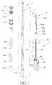
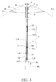
- FIGURES 1-4 comprises an opening / closing construction for an automatic umbrella according to a preferred embodiment of the present invention: a shaft assembly 1, a frame 2, a umbrella covering (not shown) arranged on the frame 2, a groove 4, a first running element 6, a second running element 5 , a drive mechanism 7 and a handle 8 in which a power source 8A is configured.
- the frame 2 comprises a plurality of ribs 21, a plurality of first auxiliary struts 22 and a plurality of second auxiliary struts 23; a first end of each rib 21 is connected to the groove 4, and a second end of each rib 21 is formed as a free segment 211; a first end of each first auxiliary strut 22 communicates with the second strut 5 and a second end of each first auxiliary strut 22 is connected to each rib 21; a first end of every second Auxiliary strut 23 is in communication with the first runner 6 and a second end of each second assist strut 23 is connected to each rib 21.
- a spring 24 is provided between the first running element 6 and each rib 21.
- the shaft assembly 1 comprises a first tube 11 and a second tube 12, wherein a length of the second tube 12 is greater than that of the first tube 11 and wherein a lower end of the second tube 12 attached to the handle 8 and an upper end of the second tube 12th the groove 4 is adjusted.
- the first pipe 11 is connected to the second pipe 12 for movement between the groove 4 and the handle 8 on the second pipe 12, and the second race member 5 and the first race member 6 are attached to the first pipe 11; wherein a limiting element 111 is attached to the first tube 11 in order to prevent movement of the second running element 5 beyond the limiting element 111.
- the restriction member 111 is a shoulder formed on the first tube 11, and in another embodiment, the restriction member 111 is a stopper ring or a screw on the first tube 11.
- the first pipe 11 is provided with a securing member 112, the construction of which is identical to that of the restricting member 111.
- a connection opening 113 is also provided on the first tube 111.
- the drive mechanism 7 comprises a threaded rod 71 and a cooperating with the threaded rod 71 slide member 72; a lower end of the threaded rod 71 is connected to the power source 8A in the handle 8, and the slider part 72 includes a driving part 720 adapted to the threaded rod 71 and female threads 721 formed on the driving part 720 and for screwing to the threaded rod 71 in that the power source 8A is activated to drive the threaded rod 71 to rotate in a clockwise and counterclockwise direction, and then the slider member 72 is driven by the threaded rod 71 to move up or down relative to the threaded rod 71.
- the slide member 72 is inserted into the second tube 12 so that its upper end is connected to the first tube 11 by inserting a connector 73 into the second tube 12 and the port 113, and the second tube 12 has one in an outer wall the same formed and extending in the longitudinal direction groove 121, so that the connecting element 73 along the groove 121 is moved up or down.
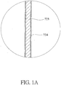
- the driving part 720 is disposed at a lower end to match the threaded rod 71, and a coupling part 722 is formed at an upper end, with a deforming part 723 communicating with the driving part 720 and the coupling part 722.
- the coupling part 722 cooperates with an inner wall of the second tube 12 and is connected to the first tube 11 by inserting the connecting member 73 into the first tube 11.
- the deforming member 723 is a rigid member to at least two rigid ropes arranged symmetrically and a plurality of rigid ropes equally spaced between the driving member 720 and the coupling member 722, two ends of each rigid cable to the drive part 720 and the coupling part 722 are connected.
- the deforming member 723 is rigid with respect to the shank as such in an axial direction X1, deforming in a torque direction Y1 and returning to its original shape.
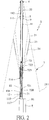
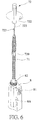
- FIG. 5 As can be seen, the threaded rod 71 acts on the slide member 72 so that it rotates; and according to the FIG. 6 stops the threaded rod 71, the actuation of the slide member 72, in which case the deformation member 723 no longer deforms to keep the thrust of the slide member 72 stable and to prevent a shock or impact of components.
- a longitudinal movement of the internal threads 721 along the threaded rod 71 corresponds to a longitudinal movement of the second race element 5 relative to the second tube 12.
- the handle 8 is formed in a lid shape to receive the power source 8A, and includes a push button 81 for activating the power source 8A to rotate clockwise or counterclockwise.
- the power source 8A is a stepped transmission or a servomotor.
- the drive part 720 is at the lower end of the threaded rod 71, ie the slide part 72 is positioned relative to the second tube 12 at the lower end of the threaded rod 71.
- the power source 8A is activated to exert a clockwise rotational force by which the threaded rod 71 is rotationally driven, with the driving member 720 moving upwardly along the threaded rod 71, the deforming member 723 displacing the coupling member 722, to cause the drive of the first tube 11, and then the first tube 11 moves upwardly relative to the second tube 12, wherein the limiting element 111 at the same time shifts the second running element 5 so that it moves upward, such that the plurality the first auxiliary struts 22 pushes the plurality of ribs 21 outwardly and the plurality of ribs 21 drives the second auxiliary struts 22 to move upwardly and actuate the first strut 6 to retract towards an upper end of the first tube 11 moved up so that the automatic screen is fully opened, the second Laufelemen t 5 drives the plurality of first auxiliary struts 22 to extend the plurality of ribs 21 of the frame 2.
- the plurality of ribs 21 is pulled by a plurality of springs 24, wherein the umbrella fabric acts on the frame 2 mandatory, so that between the frame 2 and the plurality of second Assist struts 23 forms an angle and so an upward movement of the first running element 6 is stopped.
- a lower end of the first tube 11 is covered with a protective sleeve 116.
- a buffer pad 9 is provided between the second race member 5 and the first race member 6 to dampen a shock effect between the second race member 5 and the first race member 6 when the first race member 6 is pulled upward in the direction of the second race member 5.
- a projection 114 whose outer diameter is greater than the inner diameter of the first race element 6, such that upon opening of the automatic umbrella, the projection 6 acts on the first race element 6 and so the automatic screen opens easily.
- a protective sleeve 115 and a fastening ring 117 for fixed arrangement of the protective sleeve 115 are provided on the handle 8.
- FIG. 4 As can be seen, when the automatic umbrella is fully opened, the threaded rod 71 is driven by the power source 8A to rotate relative to the driving member 720. Since the slider part 71 is made of three parts, the driving part 720 rotates by means of the deformation part 723 and the coupling part 722, whereby the deformation part 723 deforms to be in the torque direction Y1 Resistance against the drive member 720 to act, such that the drive member 720 has no influence on the coupling member 722, and wherein the slide member 72 moves in the axial direction X1 and a stable movement of the first tube 11 takes place, so that a vibration of the shaft assembly prevents a more comfortable handling of the automatic screen and extends the life of the automatic screen.
- the deformation part 723 is provided with a soundproofing layer 724 applied to the deformation part 723.
- the soundproofing layer 724 is preferably a rubber grommet or an elastic cover.
Landscapes
- Walking Sticks, Umbrellas, And Fans (AREA)
Claims (6)
- Parapluie comprenant une structure d'ouverture et de fermeture composée d'une barre (1), d'un châssis (2), d'une toile à tendre disposée sur le châssis (2), d'une une première coulisse (6) comprenant une seconde coulisse (5), d'un mécanisme d'entraînement (7) et d'une poignée (8) dans laquelle est configurée une source de force (8A), sachant que le châssis (2) comprend un grand nombre de nervures (21), un grand nombre de baleines auxiliaires primaires (22) et un grand nombre de baleines auxiliaires secondaires (23), et qu'une première extrémité de chaque nervure (21) est reliée à un élément à gorge (4), et qu'une seconde extrémité de chaque nervure (21) est configurée en segment libre (211), qu'une première extrémité de chaque baleine auxiliaire primaire (22) se trouve en liaison avec la seconde coulisse (5) et qu'une seconde extrémité de chaque baleine auxiliaire primaire (22) est reliée à chaque nervure (21), qu'une première extrémité de chaque baleine auxiliaire secondaire (23) est en liaison avec la première coulisse (6) et qu'une seconde extrémité de chaque baleine auxiliaire secondaire (23) est reliée à chaque nervure (21), sachant qu'entre la première coulisse (6) et chaque nervure (21) est prévu un ressort (24) et que la barre (1) comprend un premier tube (11) et un second tube (12), sachant qu'une longueur du second tube (12) est supérieure à celle du premier tube (11) et sachant qu'une extrémité inférieure du deuxième tube (12) est fixée contre la poignée (8) et qu'une extrémité supérieure du deuxième tube (12) est adaptée à l'élément à gorge (4), et que le premier tube (11) est disposé sur le second tube (12) pour le déplacement entre l'élément à gorge (4) et la poignée (8) sur le second tube (12), et que la seconde coulisse (5) et la première coulisse (6) sont montées contre le premier tube (11), sachant que sur le premier tube (11) est fixé un élément limitateur (111) pour empêcher un déplacement de la seconde coulisse (5) au-delà de l'élément limitateur (111), et sachant que le mécanisme d'entraînement (7) comprend une tige filetée (71) et un curseur (72) interagissant avec la tige filetée (71), et qu'une extrémité inférieure de la tige filetée (71) est reliée à la source de force (8A) logée dans la poignée (8), et sachant que le curseur (72) comprend une pièce d'entraînement (720) adaptée à la tige filetée (71) et aux filetages intérieurs (721) configurés contre la pièce d'entraînement (720) et servant au vissage avec la tige filetée (71), de sorte que la source de force (8A) devient activable pour obliger la tige filetée (71) à tourner dans le sens horaire et dans le sens antihoraire, sachant qu'ensuite le curseur (72) devient entraînable par la tige filetée (71) afin de se déplacer vers le haut et bas relativement à la tige filetée (71), sachant que le curseur (72) est introduit dans le deuxième tube (12) de sorte que son extrémité supérieure est reliée avec le premier tube (11) par le fait qu'un élément de liaison (73) est introduit dans le second tube (12) et l'orifice de raccordement (113), et sachant que le deuxième tube (12) présente, configurée dans la paroi externe dudit tube, une rainure (121) au tracé longitudinal de sorte que l'élément de liaison (73) est déplaçable le long de la rainure (121) vers le haut ou vers le bas, et sachant que la pièce d'entraînement (720) est disposée à une extrémité inférieure de manière adaptée à la tige filetée(71) et qu'une pièce d'accouplement (722) est configurée contre une partie supérieure, sachant qu'une pièce à déformation (723) se trouve en liaison avec la pièce d'entraînement (720) et la pièce d'accouplement (722), sachant que la pièce d'accouplement (722) interagit avec une paroi intérieure du second tube (12), sachant que la pièce à déformation (723) est rigide vis-à-vis de la barre (1) dans le sens axial (X1), sachant qu'elle se déforme dans un sens d'application du couple (Y1) et qu'elle reprend sa forme d'origine et que la tige filetée (71) agit sur le curseur (72) de sorte qu'elle tourne et que la tige filetée (71) stoppe l'actionnement de la pièce coulissante (72), sachant que la pièce à déformation (723) ne se déforme plus pour maintenir stable la force de poussée du curseur (72) et pour empêcher un effet de choc ou de percussion de composants, sachant que pour ouvrir le parapluie automatique la source de force (8A) dans la poignée (8) est activable afin d'exercer une force de rotation s'exerçant dans le sens horaire, force par laquelle la tige filetée (71) est entraînée en rotation, sachant que la pièce d'entraînement (720) se déplace vers le haut le long de la tige filetée (71) et sachant que la pièce à déformation (723) déplace la pièce d'accouplement (722) pour provoquer l'entraînement du premier tube (11), et sachant qu'ensuite le premier tube (11) se déplace vers le haut relativement au second tube (12) et sachant que l'élément limitateur (111) pousse simultanément la seconde coulisse (5) afin qu'elle se déplace vers le haut, de sorte que le grand nombre de baleines auxiliaires primaires (22) pousse le grand nombre de nervures (21) vers l'extérieur et que le grand nombre de nervures (21) entraîne les baleines auxiliaires secondaires (23) afin que ces dernières se déplacent vers le haut et actionnent la première coulisse (6), afin que cette dernière se déplace vers le haut en direction d'une première extrémité du premier tube (11) afin que le parapluie automatique s'ouvre entièrement, sachant que la seconde coulisse (5) entraîne le grand nombre de baleines auxiliaires primaires (22) pour faire sortir le grand nombre de nervures (21) du châssis (2), sachant que le grand nombre de nervures (21) est tiré par un grand nombre de ressorts (24), sachant que la toile à tendre agit impérativement sur le châssis (2) de sorte qu'un angle est formé entre le châssis (2) et le grand nombre de baleines auxiliaires secondaires (23) et qu'ainsi un mouvement montant de la première coulisse (6) est stoppé, sachant qu'entre la seconde coulisse (5) et la première coulisse (6) est prévu un coussinet tampon (9) pour amortir un effet d'impact entre la seconde coulisse (5) et la première coulisse (6) lorsque la première coulisse (6) est tirée vers le haut en direction de la seconde coulisse (5), et de telle sorte que pour fermer le parapluie automatique se trouve une protubérance (114) sur l'extrémité inférieure du premier tube (11), protubérance dont le diamètre extérieur est supérieur au diamètre intérieur de la première coulisse (6), de sorte que lors de l'ouverture du parapluie automatique la protubérance (114) agit sur la première coulisse (6) et qu'ainsi le parapluie automatique s'ouvre facilement, sachant qu'entre l'extrémité inférieure du second tube (12) et la poignée (8) sont prévues une douille de protection (115) et une bague de fixation (117) pour disposer fermement la douille de protection (115) sur la poignée (8), et en ce que le curseur (72) se compose de trois parties, la partie d'entraînement (720) au moyen de la pièce à déformation (723) et la pièce d'accouplement (722), sachant que la pièce à déformation (723) se déforme pour opposer une résistance, dans le sens d'exercice du couple (Y1), à la pièce d'entraînement (720), de sorte que la pièce d'entraînement (720) n'a aucune influence sur la pièce d'accouplement (722), et sachant que le curseur (72) se déplace dans le sens axial (X1) et qu'un mouvement stable du premier tube (11) a lieu, ce qui empêche la barre (1) de vibrer.
- Parapluie automatique selon la revendication 1, sachant que la pièce à déformation (723) est une pièce rigide.
- Parapluie automatique selon la revendication 1 ou 2, sachant que la pièce à déformation (723) se compose d'au moins deux câbles rigides disposés symétriquement, sachant que deux extrémités de chaque câble rigide sont reliées à la pièce d'entraînement (720) et à la pièce d'accouplement (722).
- Parapluie automatique selon la revendication 1 ou l'une des revendications 2 ou 3, sachant que la pièce à déformation (723) est composée d'un grand nombre de câbles rigides disposés à équidistance entre la pièce d'entraînement (720) et la pièce d'accouplement (722), sachant que deux extrémités de chaque câble rigide sont raccordées à la pièce d'entraînement (720) et à la pièce d'accouplement (722).
- Parapluie automatique selon la revendication 1 ou l'une des revendications 2 à 4, sachant que le premier tube (11) est muni d'une douille de protection (115) à une extrémité inférieure et sachant qu'entre la seconde coulisse (5) et la première coulisse (6) est agencé un coussinet tampon (9).
- Parapluie automatique selon la revendication 1 ou l'une des revendications 2 à 5, sachant qu'un élément limitateur (111) est disposé fixe contre le premier tube (11) pour empêcher la seconde coulisse (5) de se déplacer au-delà de l'élément limitateur (111).
Priority Applications (3)
| Application Number | Priority Date | Filing Date | Title |
|---|---|---|---|
| PL14003639T PL3015016T3 (pl) | 2014-10-27 | 2014-10-27 | Konstrukcja otwierania/zamykania dla automatycznego parasola |
| EP14003639.3A EP3015016B1 (fr) | 2014-10-27 | 2014-10-27 | Construction d'ouverture/fermeture pur un parapluie automatique |
| DK14003639.3T DK3015016T3 (en) | 2014-10-27 | 2014-10-27 | OPEN / CLOSE CONSTRUCTION FOR AN AUTOMATIC UMBRELLA |
Applications Claiming Priority (1)
| Application Number | Priority Date | Filing Date | Title |
|---|---|---|---|
| EP14003639.3A EP3015016B1 (fr) | 2014-10-27 | 2014-10-27 | Construction d'ouverture/fermeture pur un parapluie automatique |
Publications (2)
| Publication Number | Publication Date |
|---|---|
| EP3015016A1 EP3015016A1 (fr) | 2016-05-04 |
| EP3015016B1 true EP3015016B1 (fr) | 2017-06-28 |
Family
ID=51868733
Family Applications (1)
| Application Number | Title | Priority Date | Filing Date |
|---|---|---|---|
| EP14003639.3A Active EP3015016B1 (fr) | 2014-10-27 | 2014-10-27 | Construction d'ouverture/fermeture pur un parapluie automatique |
Country Status (3)
| Country | Link |
|---|---|
| EP (1) | EP3015016B1 (fr) |
| DK (1) | DK3015016T3 (fr) |
| PL (1) | PL3015016T3 (fr) |
Families Citing this family (1)
| Publication number | Priority date | Publication date | Assignee | Title |
|---|---|---|---|---|
| CN115948136B (zh) * | 2022-12-21 | 2024-08-23 | 马鞍山晨晖新材料科技有限公司 | 一种用于胶纸生产用的胶水制备反应釜和制备配方 |
Family Cites Families (2)
| Publication number | Priority date | Publication date | Assignee | Title |
|---|---|---|---|---|
| US20060151019A1 (en) * | 2005-01-07 | 2006-07-13 | Chong-Yi Lo | Electric spreading device for a parasol |
| GB2557862B (en) * | 2013-03-08 | 2019-03-27 | Xiamen Mingho Brothers Mfg Co Ltd | Full automatic opening and closing straight bone umbrella |
-
2014
- 2014-10-27 DK DK14003639.3T patent/DK3015016T3/en active
- 2014-10-27 PL PL14003639T patent/PL3015016T3/pl unknown
- 2014-10-27 EP EP14003639.3A patent/EP3015016B1/fr active Active
Non-Patent Citations (1)
| Title |
|---|
| None * |
Also Published As
| Publication number | Publication date |
|---|---|
| DK3015016T3 (en) | 2017-10-02 |
| PL3015016T3 (pl) | 2017-12-29 |
| EP3015016A1 (fr) | 2016-05-04 |
Similar Documents
| Publication | Publication Date | Title |
|---|---|---|
| EP2727490B1 (fr) | Parapluie à ouverture/fermeture entièrement automatique à plis multiples | |
| DE102007021803B4 (de) | Teleskopierbarer Schirm | |
| EP2842446B1 (fr) | Parasol inclinable | |
| EP3279416A1 (fr) | Dispositif d'amortissement | |
| DE102008014372A1 (de) | Standschirm | |
| DE102005047323A1 (de) | Teleskopierbarer Schirm, insbesondere Sonnenschirm | |
| DE202013103393U1 (de) | Schlosskonstruktion | |
| DE1459022A1 (de) | Doppelklapptuer | |
| DE69925974T2 (de) | Bauteil zum herstellen einer wand | |
| DE202013101591U1 (de) | Halterung zur Montage von gespannten Sonnen- oder Blickschutzvorrichtungen | |
| DE102015100547A1 (de) | Ausstellvorrichtung für ein Fenster oder eine Tür mit einer Energiespeichereinrichtung | |
| DE202008004468U1 (de) | Betätigungsmechanismus für einen Regenschirm | |
| EP3015016A1 (fr) | Construction d'ouverture/fermeture pur un parapluie automatique | |
| DE60302628T2 (de) | Schirm, zum Beispiel ein Sonnen- oder Regenschirm oder ähnlichem, und Halterung | |
| DE2226754A1 (de) | Selbstschliessender schirm | |
| DE202009011667U1 (de) | Teleskopischer Schraubenschlüssel | |
| DE202012104753U1 (de) | Teleskoplenker | |
| DE102019104161A1 (de) | Fenster für ein Fahrzeug oder einen Container mit einem Verriegelungsmechanismus | |
| DE102005001469A1 (de) | Reflektoreinrichtung für den Einsatz in der Fotografie | |
| DE102014206643B4 (de) | Beschlag für eine Schiebetür oder ein Schiebefenster | |
| DE102006042490A1 (de) | Vorrichtung und Verfahren zum Befestigen von Aufsatzelementen auf bauseitigen Rahmensystemen, bevorzugter Weise für Fenster und Türen | |
| DE202009005345U1 (de) | Hebelverschluss mit stirnseitigem Antrieb seiner Verriegelungsstangen | |
| EP3018280A1 (fr) | Entraînement de porte | |
| DE102016121128B3 (de) | Rohrreinigungsgerät | |
| DE102013007222A1 (de) | Taschenschirm mit Dosengriff |
Legal Events
| Date | Code | Title | Description |
|---|---|---|---|
| PUAI | Public reference made under article 153(3) epc to a published international application that has entered the european phase |
Free format text: ORIGINAL CODE: 0009012 |
|
| 17P | Request for examination filed |
Effective date: 20141110 |
|
| AK | Designated contracting states |
Kind code of ref document: A1 Designated state(s): AL AT BE BG CH CY CZ DE DK EE ES FI FR GB GR HR HU IE IS IT LI LT LU LV MC MK MT NL NO PL PT RO RS SE SI SK SM TR |
|
| AX | Request for extension of the european patent |
Extension state: BA ME |
|
| RIC1 | Information provided on ipc code assigned before grant |
Ipc: A45B 25/14 20060101AFI20170203BHEP Ipc: A45B 25/16 20060101ALI20170203BHEP |
|
| GRAJ | Information related to disapproval of communication of intention to grant by the applicant or resumption of examination proceedings by the epo deleted |
Free format text: ORIGINAL CODE: EPIDOSDIGR1 |
|
| GRAP | Despatch of communication of intention to grant a patent |
Free format text: ORIGINAL CODE: EPIDOSNIGR1 |
|
| GRAP | Despatch of communication of intention to grant a patent |
Free format text: ORIGINAL CODE: EPIDOSNIGR1 |
|
| INTG | Intention to grant announced |
Effective date: 20170331 |
|
| GRAS | Grant fee paid |
Free format text: ORIGINAL CODE: EPIDOSNIGR3 |
|
| GRAA | (expected) grant |
Free format text: ORIGINAL CODE: 0009210 |
|
| AK | Designated contracting states |
Kind code of ref document: B1 Designated state(s): AL AT BE BG CH CY CZ DE DK EE ES FI FR GB GR HR HU IE IS IT LI LT LU LV MC MK MT NL NO PL PT RO RS SE SI SK SM TR |
|
| REG | Reference to a national code |
Ref country code: GB Ref legal event code: FG4D Free format text: NOT ENGLISH |
|
| REG | Reference to a national code |
Ref country code: CH Ref legal event code: EP |
|
| REG | Reference to a national code |
Ref country code: AT Ref legal event code: REF Ref document number: 904058 Country of ref document: AT Kind code of ref document: T Effective date: 20170715 |
|
| REG | Reference to a national code |
Ref country code: IE Ref legal event code: FG4D Free format text: LANGUAGE OF EP DOCUMENT: GERMAN |
|
| REG | Reference to a national code |
Ref country code: DE Ref legal event code: R096 Ref document number: 502014004372 Country of ref document: DE |
|
| REG | Reference to a national code |
Ref country code: SE Ref legal event code: TRGR |
|
| REG | Reference to a national code |
Ref country code: CH Ref legal event code: NV Representative=s name: ISLER AND PEDRAZZINI AG, CH |
|
| REG | Reference to a national code |
Ref country code: FR Ref legal event code: PLFP Year of fee payment: 4 |
|
| REG | Reference to a national code |
Ref country code: DK Ref legal event code: T3 Effective date: 20170928 |
|
| REG | Reference to a national code |
Ref country code: NL Ref legal event code: FP |
|
| PG25 | Lapsed in a contracting state [announced via postgrant information from national office to epo] |
Ref country code: HR Free format text: LAPSE BECAUSE OF FAILURE TO SUBMIT A TRANSLATION OF THE DESCRIPTION OR TO PAY THE FEE WITHIN THE PRESCRIBED TIME-LIMIT Effective date: 20170628 Ref country code: LT Free format text: LAPSE BECAUSE OF FAILURE TO SUBMIT A TRANSLATION OF THE DESCRIPTION OR TO PAY THE FEE WITHIN THE PRESCRIBED TIME-LIMIT Effective date: 20170628 Ref country code: NO Free format text: LAPSE BECAUSE OF FAILURE TO SUBMIT A TRANSLATION OF THE DESCRIPTION OR TO PAY THE FEE WITHIN THE PRESCRIBED TIME-LIMIT Effective date: 20170928 Ref country code: GR Free format text: LAPSE BECAUSE OF FAILURE TO SUBMIT A TRANSLATION OF THE DESCRIPTION OR TO PAY THE FEE WITHIN THE PRESCRIBED TIME-LIMIT Effective date: 20170929 |
|
| REG | Reference to a national code |
Ref country code: LT Ref legal event code: MG4D |
|
| PG25 | Lapsed in a contracting state [announced via postgrant information from national office to epo] |
Ref country code: RS Free format text: LAPSE BECAUSE OF FAILURE TO SUBMIT A TRANSLATION OF THE DESCRIPTION OR TO PAY THE FEE WITHIN THE PRESCRIBED TIME-LIMIT Effective date: 20170628 Ref country code: LV Free format text: LAPSE BECAUSE OF FAILURE TO SUBMIT A TRANSLATION OF THE DESCRIPTION OR TO PAY THE FEE WITHIN THE PRESCRIBED TIME-LIMIT Effective date: 20170628 Ref country code: BG Free format text: LAPSE BECAUSE OF FAILURE TO SUBMIT A TRANSLATION OF THE DESCRIPTION OR TO PAY THE FEE WITHIN THE PRESCRIBED TIME-LIMIT Effective date: 20170928 |
|
| PG25 | Lapsed in a contracting state [announced via postgrant information from national office to epo] |
Ref country code: EE Free format text: LAPSE BECAUSE OF FAILURE TO SUBMIT A TRANSLATION OF THE DESCRIPTION OR TO PAY THE FEE WITHIN THE PRESCRIBED TIME-LIMIT Effective date: 20170628 Ref country code: RO Free format text: LAPSE BECAUSE OF FAILURE TO SUBMIT A TRANSLATION OF THE DESCRIPTION OR TO PAY THE FEE WITHIN THE PRESCRIBED TIME-LIMIT Effective date: 20170628 Ref country code: SK Free format text: LAPSE BECAUSE OF FAILURE TO SUBMIT A TRANSLATION OF THE DESCRIPTION OR TO PAY THE FEE WITHIN THE PRESCRIBED TIME-LIMIT Effective date: 20170628 |
|
| PGFP | Annual fee paid to national office [announced via postgrant information from national office to epo] |
Ref country code: DK Payment date: 20171011 Year of fee payment: 4 |
|
| PG25 | Lapsed in a contracting state [announced via postgrant information from national office to epo] |
Ref country code: IS Free format text: LAPSE BECAUSE OF FAILURE TO SUBMIT A TRANSLATION OF THE DESCRIPTION OR TO PAY THE FEE WITHIN THE PRESCRIBED TIME-LIMIT Effective date: 20171028 Ref country code: ES Free format text: LAPSE BECAUSE OF FAILURE TO SUBMIT A TRANSLATION OF THE DESCRIPTION OR TO PAY THE FEE WITHIN THE PRESCRIBED TIME-LIMIT Effective date: 20170628 Ref country code: SM Free format text: LAPSE BECAUSE OF FAILURE TO SUBMIT A TRANSLATION OF THE DESCRIPTION OR TO PAY THE FEE WITHIN THE PRESCRIBED TIME-LIMIT Effective date: 20170628 |
|
| PGFP | Annual fee paid to national office [announced via postgrant information from national office to epo] |
Ref country code: IE Payment date: 20171010 Year of fee payment: 4 Ref country code: SE Payment date: 20171011 Year of fee payment: 4 |
|
| REG | Reference to a national code |
Ref country code: DE Ref legal event code: R097 Ref document number: 502014004372 Country of ref document: DE |
|
| PLBE | No opposition filed within time limit |
Free format text: ORIGINAL CODE: 0009261 |
|
| STAA | Information on the status of an ep patent application or granted ep patent |
Free format text: STATUS: NO OPPOSITION FILED WITHIN TIME LIMIT |
|
| PG25 | Lapsed in a contracting state [announced via postgrant information from national office to epo] |
Ref country code: MC Free format text: LAPSE BECAUSE OF FAILURE TO SUBMIT A TRANSLATION OF THE DESCRIPTION OR TO PAY THE FEE WITHIN THE PRESCRIBED TIME-LIMIT Effective date: 20170628 |
|
| 26N | No opposition filed |
Effective date: 20180329 |
|
| PG25 | Lapsed in a contracting state [announced via postgrant information from national office to epo] |
Ref country code: LU Free format text: LAPSE BECAUSE OF NON-PAYMENT OF DUE FEES Effective date: 20171027 |
|
| PG25 | Lapsed in a contracting state [announced via postgrant information from national office to epo] |
Ref country code: SI Free format text: LAPSE BECAUSE OF FAILURE TO SUBMIT A TRANSLATION OF THE DESCRIPTION OR TO PAY THE FEE WITHIN THE PRESCRIBED TIME-LIMIT Effective date: 20170628 |
|
| REG | Reference to a national code |
Ref country code: FR Ref legal event code: PLFP Year of fee payment: 5 |
|
| PG25 | Lapsed in a contracting state [announced via postgrant information from national office to epo] |
Ref country code: MT Free format text: LAPSE BECAUSE OF FAILURE TO SUBMIT A TRANSLATION OF THE DESCRIPTION OR TO PAY THE FEE WITHIN THE PRESCRIBED TIME-LIMIT Effective date: 20170628 |
|
| REG | Reference to a national code |
Ref country code: DK Ref legal event code: EBP Effective date: 20181031 |
|
| REG | Reference to a national code |
Ref country code: SE Ref legal event code: EUG |
|
| PG25 | Lapsed in a contracting state [announced via postgrant information from national office to epo] |
Ref country code: HU Free format text: LAPSE BECAUSE OF FAILURE TO SUBMIT A TRANSLATION OF THE DESCRIPTION OR TO PAY THE FEE WITHIN THE PRESCRIBED TIME-LIMIT; INVALID AB INITIO Effective date: 20141027 |
|
| REG | Reference to a national code |
Ref country code: IE Ref legal event code: MM4A |
|
| PG25 | Lapsed in a contracting state [announced via postgrant information from national office to epo] |
Ref country code: SE Free format text: LAPSE BECAUSE OF NON-PAYMENT OF DUE FEES Effective date: 20181028 |
|
| PG25 | Lapsed in a contracting state [announced via postgrant information from national office to epo] |
Ref country code: CY Free format text: LAPSE BECAUSE OF FAILURE TO SUBMIT A TRANSLATION OF THE DESCRIPTION OR TO PAY THE FEE WITHIN THE PRESCRIBED TIME-LIMIT Effective date: 20170628 Ref country code: DK Free format text: LAPSE BECAUSE OF NON-PAYMENT OF DUE FEES Effective date: 20181031 Ref country code: IE Free format text: LAPSE BECAUSE OF NON-PAYMENT OF DUE FEES Effective date: 20181027 |
|
| PG25 | Lapsed in a contracting state [announced via postgrant information from national office to epo] |
Ref country code: MK Free format text: LAPSE BECAUSE OF FAILURE TO SUBMIT A TRANSLATION OF THE DESCRIPTION OR TO PAY THE FEE WITHIN THE PRESCRIBED TIME-LIMIT Effective date: 20170628 |
|
| PGFP | Annual fee paid to national office [announced via postgrant information from national office to epo] |
Ref country code: CZ Payment date: 20191023 Year of fee payment: 6 Ref country code: FI Payment date: 20191009 Year of fee payment: 6 |
|
| PG25 | Lapsed in a contracting state [announced via postgrant information from national office to epo] |
Ref country code: TR Free format text: LAPSE BECAUSE OF FAILURE TO SUBMIT A TRANSLATION OF THE DESCRIPTION OR TO PAY THE FEE WITHIN THE PRESCRIBED TIME-LIMIT Effective date: 20170628 |
|
| PG25 | Lapsed in a contracting state [announced via postgrant information from national office to epo] |
Ref country code: PT Free format text: LAPSE BECAUSE OF FAILURE TO SUBMIT A TRANSLATION OF THE DESCRIPTION OR TO PAY THE FEE WITHIN THE PRESCRIBED TIME-LIMIT Effective date: 20170628 |
|
| PG25 | Lapsed in a contracting state [announced via postgrant information from national office to epo] |
Ref country code: AL Free format text: LAPSE BECAUSE OF FAILURE TO SUBMIT A TRANSLATION OF THE DESCRIPTION OR TO PAY THE FEE WITHIN THE PRESCRIBED TIME-LIMIT Effective date: 20170628 |
|
| REG | Reference to a national code |
Ref country code: FI Ref legal event code: MAE |
|
| PG25 | Lapsed in a contracting state [announced via postgrant information from national office to epo] |
Ref country code: FI Free format text: LAPSE BECAUSE OF NON-PAYMENT OF DUE FEES Effective date: 20201027 Ref country code: CZ Free format text: LAPSE BECAUSE OF NON-PAYMENT OF DUE FEES Effective date: 20201027 |
|
| PGFP | Annual fee paid to national office [announced via postgrant information from national office to epo] |
Ref country code: NL Payment date: 20221123 Year of fee payment: 9 Ref country code: IT Payment date: 20221129 Year of fee payment: 9 Ref country code: GB Payment date: 20221117 Year of fee payment: 9 Ref country code: FR Payment date: 20221130 Year of fee payment: 9 |
|
| PGFP | Annual fee paid to national office [announced via postgrant information from national office to epo] |
Ref country code: PL Payment date: 20221118 Year of fee payment: 9 Ref country code: BE Payment date: 20221129 Year of fee payment: 9 |
|
| REG | Reference to a national code |
Ref country code: NL Ref legal event code: MM Effective date: 20231101 |
|
| REG | Reference to a national code |
Ref country code: BE Ref legal event code: MM Effective date: 20231031 |
|
| GBPC | Gb: european patent ceased through non-payment of renewal fee |
Effective date: 20231027 |
|
| PG25 | Lapsed in a contracting state [announced via postgrant information from national office to epo] |
Ref country code: GB Free format text: LAPSE BECAUSE OF NON-PAYMENT OF DUE FEES Effective date: 20231027 |
|
| PG25 | Lapsed in a contracting state [announced via postgrant information from national office to epo] |
Ref country code: NL Free format text: LAPSE BECAUSE OF NON-PAYMENT OF DUE FEES Effective date: 20231101 |
|
| PG25 | Lapsed in a contracting state [announced via postgrant information from national office to epo] |
Ref country code: NL Free format text: LAPSE BECAUSE OF NON-PAYMENT OF DUE FEES Effective date: 20231101 Ref country code: GB Free format text: LAPSE BECAUSE OF NON-PAYMENT OF DUE FEES Effective date: 20231027 Ref country code: FR Free format text: LAPSE BECAUSE OF NON-PAYMENT OF DUE FEES Effective date: 20231031 |
|
| PG25 | Lapsed in a contracting state [announced via postgrant information from national office to epo] |
Ref country code: BE Free format text: LAPSE BECAUSE OF NON-PAYMENT OF DUE FEES Effective date: 20231031 |
|
| PG25 | Lapsed in a contracting state [announced via postgrant information from national office to epo] |
Ref country code: IT Free format text: LAPSE BECAUSE OF NON-PAYMENT OF DUE FEES Effective date: 20231027 |
|
| PG25 | Lapsed in a contracting state [announced via postgrant information from national office to epo] |
Ref country code: IT Free format text: LAPSE BECAUSE OF NON-PAYMENT OF DUE FEES Effective date: 20231027 |
|
| REG | Reference to a national code |
Ref country code: DE Ref legal event code: R082 Ref document number: 502014004372 Country of ref document: DE Representative=s name: MAIWALD GMBH, DE |
|
| PG25 | Lapsed in a contracting state [announced via postgrant information from national office to epo] |
Ref country code: PL Free format text: LAPSE BECAUSE OF NON-PAYMENT OF DUE FEES Effective date: 20231027 |
|
| REG | Reference to a national code |
Ref country code: CH Ref legal event code: U11 Free format text: ST27 STATUS EVENT CODE: U-0-0-U10-U11 (AS PROVIDED BY THE NATIONAL OFFICE) Effective date: 20251101 |
|
| PGFP | Annual fee paid to national office [announced via postgrant information from national office to epo] |
Ref country code: DE Payment date: 20250814 Year of fee payment: 12 |
|
| PGFP | Annual fee paid to national office [announced via postgrant information from national office to epo] |
Ref country code: AT Payment date: 20251009 Year of fee payment: 12 |
|
| PGFP | Annual fee paid to national office [announced via postgrant information from national office to epo] |
Ref country code: CH Payment date: 20251101 Year of fee payment: 12 |