EP3015201B1 - Hauptspindelvorrichtung für werkzeugmaschine und werkzeugmaschine - Google Patents
Hauptspindelvorrichtung für werkzeugmaschine und werkzeugmaschine Download PDFInfo
- Publication number
- EP3015201B1 EP3015201B1 EP13887986.1A EP13887986A EP3015201B1 EP 3015201 B1 EP3015201 B1 EP 3015201B1 EP 13887986 A EP13887986 A EP 13887986A EP 3015201 B1 EP3015201 B1 EP 3015201B1
- Authority
- EP
- European Patent Office
- Prior art keywords
- spindle
- rigidity
- tool
- bearing case
- bearing
- Prior art date
- Legal status (The legal status is an assumption and is not a legal conclusion. Google has not performed a legal analysis and makes no representation as to the accuracy of the status listed.)
- Not-in-force
Links
Images



Classifications
-
- B—PERFORMING OPERATIONS; TRANSPORTING
- B23—MACHINE TOOLS; METAL-WORKING NOT OTHERWISE PROVIDED FOR
- B23Q—DETAILS, COMPONENTS, OR ACCESSORIES FOR MACHINE TOOLS, e.g. ARRANGEMENTS FOR COPYING OR CONTROLLING; MACHINE TOOLS IN GENERAL CHARACTERISED BY THE CONSTRUCTION OF PARTICULAR DETAILS OR COMPONENTS; COMBINATIONS OR ASSOCIATIONS OF METAL-WORKING MACHINES, NOT DIRECTED TO A PARTICULAR RESULT
- B23Q1/00—Members which are comprised in the general build-up of a form of machine, particularly relatively large fixed members
- B23Q1/70—Stationary or movable members for carrying working-spindles for attachment of tools or work
-
- B—PERFORMING OPERATIONS; TRANSPORTING
- B23—MACHINE TOOLS; METAL-WORKING NOT OTHERWISE PROVIDED FOR
- B23Q—DETAILS, COMPONENTS, OR ACCESSORIES FOR MACHINE TOOLS, e.g. ARRANGEMENTS FOR COPYING OR CONTROLLING; MACHINE TOOLS IN GENERAL CHARACTERISED BY THE CONSTRUCTION OF PARTICULAR DETAILS OR COMPONENTS; COMBINATIONS OR ASSOCIATIONS OF METAL-WORKING MACHINES, NOT DIRECTED TO A PARTICULAR RESULT
- B23Q1/00—Members which are comprised in the general build-up of a form of machine, particularly relatively large fixed members
- B23Q1/25—Movable or adjustable work or tool supports
- B23Q1/26—Movable or adjustable work or tool supports characterised by constructional features relating to the co-operation of relatively movable members; Means for preventing relative movement of such members
- B23Q1/262—Movable or adjustable work or tool supports characterised by constructional features relating to the co-operation of relatively movable members; Means for preventing relative movement of such members with means to adjust the distance between the relatively slidable members
- B23Q1/265—Movable or adjustable work or tool supports characterised by constructional features relating to the co-operation of relatively movable members; Means for preventing relative movement of such members with means to adjust the distance between the relatively slidable members between rotating members
-
- F—MECHANICAL ENGINEERING; LIGHTING; HEATING; WEAPONS; BLASTING
- F16—ENGINEERING ELEMENTS AND UNITS; GENERAL MEASURES FOR PRODUCING AND MAINTAINING EFFECTIVE FUNCTIONING OF MACHINES OR INSTALLATIONS; THERMAL INSULATION IN GENERAL
- F16C—SHAFTS; FLEXIBLE SHAFTS; ELEMENTS OR CRANKSHAFT MECHANISMS; ROTARY BODIES OTHER THAN GEARING ELEMENTS; BEARINGS
- F16C25/00—Bearings for exclusively rotary movement adjustable for wear or play
- F16C25/06—Ball or roller bearings
- F16C25/08—Ball or roller bearings self-adjusting
-
- F—MECHANICAL ENGINEERING; LIGHTING; HEATING; WEAPONS; BLASTING
- F16—ENGINEERING ELEMENTS AND UNITS; GENERAL MEASURES FOR PRODUCING AND MAINTAINING EFFECTIVE FUNCTIONING OF MACHINES OR INSTALLATIONS; THERMAL INSULATION IN GENERAL
- F16C—SHAFTS; FLEXIBLE SHAFTS; ELEMENTS OR CRANKSHAFT MECHANISMS; ROTARY BODIES OTHER THAN GEARING ELEMENTS; BEARINGS
- F16C27/00—Elastic or yielding bearings or bearing supports, for exclusively rotary movement
- F16C27/04—Ball or roller bearings, e.g. with resilient rolling bodies
-
- F—MECHANICAL ENGINEERING; LIGHTING; HEATING; WEAPONS; BLASTING
- F16—ENGINEERING ELEMENTS AND UNITS; GENERAL MEASURES FOR PRODUCING AND MAINTAINING EFFECTIVE FUNCTIONING OF MACHINES OR INSTALLATIONS; THERMAL INSULATION IN GENERAL
- F16C—SHAFTS; FLEXIBLE SHAFTS; ELEMENTS OR CRANKSHAFT MECHANISMS; ROTARY BODIES OTHER THAN GEARING ELEMENTS; BEARINGS
- F16C19/00—Bearings with rolling contact, for exclusively rotary movement
- F16C19/54—Systems consisting of a plurality of bearings with rolling friction
- F16C19/546—Systems with spaced apart rolling bearings including at least one angular contact bearing
- F16C19/547—Systems with spaced apart rolling bearings including at least one angular contact bearing with two angular contact rolling bearings
- F16C19/548—Systems with spaced apart rolling bearings including at least one angular contact bearing with two angular contact rolling bearings in O-arrangement
-
- F—MECHANICAL ENGINEERING; LIGHTING; HEATING; WEAPONS; BLASTING
- F16—ENGINEERING ELEMENTS AND UNITS; GENERAL MEASURES FOR PRODUCING AND MAINTAINING EFFECTIVE FUNCTIONING OF MACHINES OR INSTALLATIONS; THERMAL INSULATION IN GENERAL
- F16C—SHAFTS; FLEXIBLE SHAFTS; ELEMENTS OR CRANKSHAFT MECHANISMS; ROTARY BODIES OTHER THAN GEARING ELEMENTS; BEARINGS
- F16C2322/00—Apparatus used in shaping articles
- F16C2322/39—General buildup of machine tools, e.g. spindles, slides, actuators
-
- F—MECHANICAL ENGINEERING; LIGHTING; HEATING; WEAPONS; BLASTING
- F16—ENGINEERING ELEMENTS AND UNITS; GENERAL MEASURES FOR PRODUCING AND MAINTAINING EFFECTIVE FUNCTIONING OF MACHINES OR INSTALLATIONS; THERMAL INSULATION IN GENERAL
- F16C—SHAFTS; FLEXIBLE SHAFTS; ELEMENTS OR CRANKSHAFT MECHANISMS; ROTARY BODIES OTHER THAN GEARING ELEMENTS; BEARINGS
- F16C35/00—Rigid support of bearing units; Housings, e.g. caps, covers
- F16C35/04—Rigid support of bearing units; Housings, e.g. caps, covers in the case of ball or roller bearings
- F16C35/06—Mounting or dismounting of ball or roller bearings; Fixing them onto shaft or in housing
- F16C35/07—Fixing them on the shaft or housing with interposition of an element
- F16C35/077—Fixing them on the shaft or housing with interposition of an element between housing and outer race ring
Definitions
- the present invention relates to a spindle device for a machine tool, and the machine tool.
- the machine tool which carries out processing such as cutting by moving a tool relative to a workpiece.
- the machine tool comprises a spindle device including a spindle to which the tool is fitted and a motor or the like for rotating the spindle.
- the spindle device is generally formed so that the tool can be replaced, and a plurality of processes can be carried out by tool replacement.
- Patent Literature 1 discloses a peripheral velocity switching device which can change a preload of a bearing of the spindle, and switches a bearing set of the spindle according to a rotational speed of the spindle. As disclosed, this switching device applies a preload to a large bearing set disposed in front of the spindle during low-speed rotation. When a switch piston is moved by hydraulic pressure, the preload is applied to the large bearing set. On the other hand, during high-speed rotation, the large bearing set is in a state of no preload application. As disclosed, a tapered part is formed at an end of the switch piston, and a preload is absorbed when the preload of a pressure fluid is excessively large.
- Patent Literature 2 discloses a spindle device which includes a diaphragm attached to an outer peripheral surface of a rear bearing case for supporting a spindle and an inner wall of a spindle head.
- the diaphragm supports the rear bearing case on an inner wall of a housing of the spindle head.
- the diaphragm supports the spindle while being elastically deformed in an axial direction but supports the spindle with high rigidity in a radial direction.
- processing accuracy of a machine tool can be improved by increasing the support rigidity for supporting a spindle.
- the cutting can be carried out according to a desired amount.
- deeper cutting which increases the amount to be cut at once can be carried out.
- the spindle device is manufactured by setting the support rigidity so as to mainly satisfy the requirement of the deeper cutting.
- the spindle device is designed to satisfy support rigidity required when a tool having a large diameter is fitted.
- the tool may vibrate during processing.
- a reaction force applied to the tool which is currently processing a workpiece may cause the tool to vibrate.
- processing accuracy of a processed surface of the workpiece is reduced, and processing efficiency is also reduced.
- vibration occurs more easily.
- the processed surface may be finished by the tool having the small diameter.
- rigidity of the tool is less than the support rigidity of the spindle of the spindle device, and thus the tool may vibrate.
- chattering vibration may occur.
- processing accuracy (processed surface quality) or processing efficiency is reduced in some cases, for example, chattering marks may be formed on the processed surface.
- a spindle device for a machine tool comprises a spindle to which a tool is fitted, a bearing for rotatably supporting the spindle, a bearing case for holding the bearing, a housing in which the spindle, the bearing, and the bearing case are arranged, a rigidity switching device supporting the bearing case on the housing and capable of switching support rigidity for supporting the bearing case at a plurality of stages of rigidity including low rigidity and high rigidity higher than the low rigidity, and a vibration damping device disposed between the housing and the bearing case and actuated when the rigidity switching device supports the bearing case with the low rigidity.
- the vibration damping device includes a friction member disposed in a contact part of the housing and the bearing case.
- the rigidity switching device is formed to move the bearing case along a rotational axis of the spindle in the housing, the bearing case includes a tapered part in which a diameter of an outer surface is gradually reduced, and the rigidity switching device can support the bearing case with the high rigidity by moving the bearing case to press the tapered part to the housing, and support the bearing case with the low rigidity by providing the tapered part with a gap.
- the spindle device can further comprise a plate-like member supporting the bearing case on the housing and having a thickness direction set nearly parallel to the rotational axis of the spindle, and the bearing case can have an end of a side on which the tool is disposed and which is supported by the rigidity switching device, and an end of a side opposite to the side on which the tool is disposed and which is supported by the plate-like member.
- the spindle device can further comprise a displacement sensor for detecting displacement of the spindle with respect to the housing.
- the rigidity switching device normally supports the bearing case with the high rigidity, and can be switched to support the bearing case with the low rigidity when a predesignated tool is fitted to the spindle.
- the rigidity switching device can support the bearing case with the low rigidity when a diameter of the tool fitted to the spindle is smaller than a preset value, and support the bearing case with the high rigidity when the diameter of the tool fitted to the spindle is equal to or larger than the preset value.
- a machine tool comprises the aforementioned spindle device, and when the rigidity switching device switches the support rigidity of the bearing case to the low rigidity, a tool length offset value of a NC device is rewritten only by a value equivalent to a moving amount of the bearing case along the rotational axis of the spindle.
- the present invention can provide a spindle device for a machine tool which can prevent vibration of a small-diameter tool or the like and improve processing accuracy (processed surface quality) for a workpiece and processing efficiency, and the machine tool.
- the spindle device which rotates a spindle having a tool fitted thereto can be disposed in any machine tool.
- the spindle device can be disposed in a machine tool such as a horizontal or vertical machining center, a milling machine, or a boring machine.
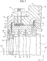
- FIG. 1 is a schematic partial sectional view of the spindle device according to the embodiment.
- the spindle device includes a spindle 1 for supporting a tool 2, and a housing in which the spindle 1 is disposed.
- the housing according to the embodiment includes a spindle head housing 10, a front housing 11, and a front end housing 12.
- the spindle device includes a built-in type rotary machine.
- a stator 7 is disposed on an inner surface of the spindle head housing 10.
- a rotor 6 is disposed on an outer surface of the spindle 1.
- the stator 7 and the rotor 6 constitute the rotary machine.
- the spindle 1 is formed into a cylindrical shape, and rotated in the spindle head housing 10.
- a side on which the tool 2 is fixed is referred to as a front side
- a side which is opposite to the fixed side of the tool 2 is referred to as a rear side.
- the extending direction of the rotational axis 101 of the spindle 1 is referred to as a Z-axis direction.
- An end of the front side of the spindle 1 is supported by the front housing 11 via a bearing, namely a front bearing, and bearing cases 14 and 15 for holding the front bearing.
- the front bearing supports the spindle 1 which is rotatable around the rotational axis 101.
- the front bearing according to the embodiment includes a pair of angular bearings 21 arranged back to back, and a roller bearing 22.
- the roller bearing 22 according to the embodiment includes a cylindrical roller.
- the angular bearing 21 provides, even when a force is applied to the spindle 1 in the extending direction of the rotational axis 101, a force to counter this force.
- the angular bearing 21 has a function of suppressing movement of the spindle 1 in the extending direction of the rotational axis 101.
- the bearing cases 14 and 15 are formed to cover the angular bearings 21 and the roller bearing 22.
- the bearing case 14 is disposed between the front bearing and the front housing 11.
- the bearing case 14 and the bearing case 15 according to the embodiment are fixed to each other.
- the bearing case 14 and the bearing case 15 are formed by separate members. However, it is not limited to the above-described embodiment, and the bearing case 14 and the bearing case 15 may be integrally formed by one member.
- the front bearing and the bearing cases 14 and 15 are arranged in the housing.
- the rear bearing supports the spindle 1 to be rotatable around the rotational axis 101.
- the rear bearing according to the embodiment includes a roller bearing 23.
- the roller bearing 23 according to the embodiment includes a cylindrical roller. An outer ring of the roller bearing 23 is pressed toward the bearing case 17 via a bearing pressing member 18. This roller bearing 23 is supported by the spindle head housing 10 via the bearing case 17.
- a nut 30 is fixed to the end of the rear side of the spindle 1.
- an inner ring of the roller bearing 23 is fixed to the spindle 1 via a sleeve 25 and collars 26 and 27.
- the inner ring of the roller bearing 23 bites into a tapered part of the spindle 1 to apply a preload to the roller bearing 23.
- a draw bar 42 is disposed to extend along the rotational axis 101.
- the draw bar 42 is formed into a bar shape.
- a disc spring 43 is disposed around the draw bar 42.
- a nut 44 is disposed at an end of a rear side of the disc spring 43. The nut 44 is fixed to the draw bar 42.
- the spindle 1 includes a collet 45 engaged with the draw bar 42.
- the draw bar 42 is urged to a rear side indicated by an arrow 111 by the disc spring 43 to be engaged with the collet 45.
- the collet 45 is set in a state where an end of a front side is open.
- the collet 45 is engaged with a tool holder 3 to hold the tool holder 3.
- the collet 45 is formed to be disengaged from the tool holder 3 when the draw bar 42 is pressed toward the front side.
- the spindle device includes a hydraulic cylinder 5 for pressing the draw bar 42 to the front side.
- a hydraulic cylinder 5 for pressing the draw bar 42 to the front side.
- fixing of the tool holder 3 is released.
- the tool 2 is fixed to the tool holder 3.
- the tool 2 can be replaced together with the tool holder 3.
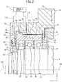
- FIG. 2 is a schematic enlarged sectional view of the front bearing and the bearing case portion.
- the outer rings of the angular bearing 21 and the roller bearing 22 are supported by the bearing cases 14 and 15.
- a collar 36 is disposed between the angular bearing 21 and the roller bearing 22.
- the bearing case 14 includes a cylindrical part 14b formed to be nearly constant in thickness along the rotational axis 101.
- a gap part 35 having a slight gap between a surface of an outer side of the cylindrical part 14b and an inner surface of the front housing 11 is formed.
- Height of the gap part 35 is preferably, for example, about several tens of ⁇ m in a diameter direction of the spindle 1.
- the surface of the outer side of the cylindrical part 14b and the inner surface of the front housing 11 are preferably separated from each other by several tens of ⁇ m.
- the bearing case 14 includes a piston part 14c at the end of the front side.
- the bearing case 14 includes a tapered part 14a formed between the piston part 14c and the cylindrical part 14b.
- the tapered part 14a has its outer diameter gradually reduced toward the rear side.
- the front housing 11 includes a tapered hole part 11a formed in a portion facing the tapered part 14a.
- the tapered hole part 11a has its inner diameter gradually reduced toward the rear side.
- the tapered hole part 11a according to the embodiment is formed to come into surface-contact with the tapered part 14a when the tapered part 14a is pressed, and simultaneously the piston part 14c comes into surface-contact with the front end of the front housing 11.
- the bearing case 14 is bound two sides.
- the ends of the rear sides of the bearing cases 14 and 15 are supported by a diaphragm 31.
- the diaphragm 31 is a plate-like member formed into a plate shape by a metal.
- the diaphragm 31 has its thickness direction which is set nearly parallel to a direction of the rotational axis 101 of the spindle 1.
- the diaphragm 31 has its end of an outer side in a diameter direction fixed to the front housing 11, and its end of an inner side in the diameter direction fixed to the bearing case 15.
- a nut 29 is disposed in front of the roller bearing 22 via a collar 37.
- a sleeve 24 is disposed behind the angular bearing 21.
- the roller bearing 22 is pressed via the collar 37.
- An inner ring of the roller bearing 22 bites into the tapered part of the spindle 1 to apply a preload to the roller bearing 22.
- an inner ring of the angular bearing 21 of the front side is pressed to the rear side via the collar 36.
- This pressing force is transmitted to an outer ring of the angular bearing 21 of the front side, an outer ring of the angular bearing 21 of the rear side, and an inner ring of the angular bearing 21 of the rear side in this order. Accordingly, a preload is also applied to the angular bearing 21.
- a seal member 16 is disposed in front of the nut 29.
- the seal member 16 suppresses flowing-out of lubricating oil supplied to the front bearing, and prevents entry of chips into the spindle device.
- the seal member 16 constitutes, for example, a labyrinth seal having concave and convex patterns formed on its surface.
- the spindle device includes a moving device for moving the bearing cases 14 and 15 in the direction of the rotational axis 101 of the spindle 1 in the housing.
- An oil chamber 63 is formed in front of the piston part 14c of the bearing case 14.
- An oil path 61 is formed in the front end housing 12. The oil path 61 communicates with the oil chamber 63.
- Eight equally distributed oil chambers 64 are formed on a front end surface of the front housing 11 of the rear side of the piston part 14c.
- An oil path 62 is formed in the front housing 11. The oil path 62 communicates with the oil chamber 64.
- the moving device includes a hydraulic device 8 for supplying high-pressure control oil to the oil chambers 63 and 64.
- a hydraulic device 8 for supplying high-pressure control oil to one of the oil chambers 63 and 64 from the hydraulic device 8, the piston part 14c can be moved along the extending direction of the rotational axis 101.
- the moving device can move the beating cases 14 and 15 along the direction of the rotational axis 101 of the spindle 1.
- the spindle device includes a vibration damping device for accelerating damping of vibrations generated in the bearing case 14 and the spindle 1.
- the vibration damping device is provided between the housing and the bearing case 14.
- the vibration damping device includes a friction member 65 fixed to the front end housing 12.
- the friction member 65 is provided in a contact part of the housing and the bearing case 14.
- the friction member 65 is disposed to face an end surface of the front side of the bearing case 14.
- the friction member 65 according to the embodiment is formed into a plate shape.
- the friction member 65 has its thickness direction set nearly parallel to the direction of the rotational axis 101.
- the spindle device includes a rigidity switching device capable of switching, at a plurality of stages, support rigidity for supporting the bearing cases 14 and 15 on the housing.
- the rigidity switching device supports the bearing cases 14 and 15, at two stages, low rigidity and high rigidity higher than the low rigidity.
- the rigidity switching device includes a moving device, and switches rigidity by moving the bearing cases 14 and 15.
- the spindle 1 is supported with high rigidity.
- the hydraulic device 8 supplies high-pressure control oil to the oil chamber 63 as indicated by an arrow 112. From the oil chamber 64, the stored control oil flows out as indicated by an arrow 113.
- the piston part 14c of the bearing case 14 is pressed by hydraulic pressure of the control oil supplied to the oil chamber 63.
- the bearing cases 14 and 15 are pressed to the rear side as indicated by an arrow 114.
- the tapered part 14a of the bearing case 14 closely contacts to the tapered hole part 11a of the front housing 11 and, simultaneously, the rear side of the piston part 14c of the bearing case 14 closely contacts to the front end surface of the front housing 11. Accordingly, the ends of the front sides of the bearing cases 14 and 15 are bound in a diameter direction indicated by an arrow 116 and an axial direction indicated by the arrow 114. The ends of the rear sides of the bearing cases 14 and 15 are bound by the diaphragm 31 in the diameter direction.
- the spindle 1 has the ends of the front sides bound in the diameter direction and in the axial direction in addition to the ends of the rear sides of the bearing cases 14 and 15, and thus the bearing cases 14 and 15 can be supported on the housing with high rigidity.
- FIG. 3 is another schematic enlarged sectional view of the portions of the front bearing and the bearing case of the spindle device according to the embodiment.
- the hydraulic device 8 supplies high-pressure control oil to the oil chamber 64 as indicated by an arrow 112.
- the control oil stored in the oil chamber 63 flows out as indicated by an arrow 113.
- the bearing cases 14 and 15 move along the rotational axis 101 in a direction indicated by an arrow 115. In other words, the bearing cases 14 and 15 move to the front side.
- the tapered part 14a of the bearing case 14 moves away from the tapered hole part 11a of the front housing 11.
- Moving amounts of the bearing cases 14 and 15 in this case are preferably small, about several hundreds of ⁇ m.
- the front end surface of the piston part 14c of the bearing case 14 comes into contact with the friction member 65.
- the gap between the tapered part 14a and the tapered hole part 11a is, for example, several tens of ⁇ m.
- the bearing cases 14 and 15 support the angular bearing 21 and the roller bearing 22, and the angular bearing 21 and the roller bearing 22 support the spindle 1. Accordingly, the movements of the bearing cases 14 and 15 cause the movement of the spindle 1 in the direction indicated by the arrow 115.
- the seal member 16 protrudes from a surface of the front end housing 12. This moving amount pz of the spindle 1 is, for example, about several hundreds of ⁇ m as described above.
- the bearing cases 14 and 15 When the bearing cases 14 and 15 move to the front side, the diaphragm 31 is slightly deformed. The ends of the rear sides of the bearing cases 14 and 15 are bound by the diaphragm 31 in the diameter direction. However, the end of the front side of the bearing case 14 is set in a state of not receiving strong binding. Thus, the bearing cases 14 and 15 can be supported on the housing with low rigidity. In other words, the spindle 1 can be supported on the housing with low rigidity.
- the support rigidity of the spindle 1 can be changed.
- the inner ring slides with respect to the roller of the roller bearing 23 to move the spindle 1.
- a normal state of the spindle device is the state of the high rigidity illustrated in FIG. 2 , and employed for many processing operations.
- the state illustrated in FIG. 2 is suitable when the tool 2 of the large diameter is used, when deeper cutting having a large cutting-in amount is carried out, or the like.
- the high support rigidity can be achieved by pressing the tapered part 14a and the piston part 14c of the bearing case 14 into contact with the front housing 11. As a result, processing can be carried out with high accuracy.
- the spindle device is set in the state of low rigidity illustrated in FIG. 3 .
- the ends of the rear sides of the bearing cases 14 and 15 are strongly bound by the diaphragm 31 in the diameter direction.
- the ends of the front sides of the bearing cases 14 and 15 can vibrate with slight amplitude in the diameter direction indicated by the arrow 116 since the ends are not bound strongly.
- the small vibration of the spindle 1 causes sliding of the end surface of the piston part 14c of the bearing case 14 with the friction member 65. Accordingly, the vibration of the spindle 1 can be damped by friction. As a result, the vibration generated in the tool 2 is suppressed to enable processing with high accuracy.
- the processing can be carried out while suppressing chattering vibration. This processing is suitable when finish processing is carried out by using the tool 2 of the small diameter or the like.
- the vibration damping device according to the embodiment is actuated when the rigidity switching device supports the bearing case 14 with low rigidity.
- the fiction member 65 for suppressing the vibration of the spindle 1 preferably employs a member which smoothly slides with the bearing case 14 even with micro vibration.
- the friction member 65 is preferably made of a material having a small difference between a static friction coefficient and a dynamic friction coefficient.
- the friction member 65 is preferably a low friction sliding member.
- the friction member 65 according to the embodiment is made of a fluorine resin.
- the fluorine resin is a material having a static friction coefficient set larger by about 1.0 to 1.1 times than a dynamic friction coefficient. Accordingly, even with vibration of very small amplitude, the friction member 65 and the bearing case 14 smoothly slide with each other. Vibration energy can be effectively converted into thermal energy. Even when chattering vibration occurs, the vibration can be effectively damped by friction.
- the oil chamber 63 is formed in front of the piston part 14c. Accordingly, the control oil also moves to a surface of the friction member 65, and a viscous damping effect of the control oil can be provided.
- the fiction member 65 according to the embodiment is fixed to the front end housing 12. However, it is not limited to the above-described embodiment, and the friction member 65 can be disposed in a portion where the bearing case slides with respect to the housing. For example, the fiction member may be disposed in the bearing case.
- the diaphragm 31 is preferably formed so that rigidity in the diameter direction can be sufficiently large. In addition, preferably, an elastic force of the diaphragm 31 in the extending direction of the rotational axis 101 is appropriately large.
- a diaphragm 31 can be made of metal.
- FIG. 4 is a diagram illustrating a stability limit line when a tool of a small diameter is fitted to a spindle device according to comparative example to carry out processing simulation.
- the spindle device according to comparative example does not include the rigidity switching device of the embodiment, but always supports a spindle with high support rigidity.
- FIG. 5 is a diagram illustrating a stability limit line when a tool of a small diameter is fitted to the spindle device according to the embodiment to carry out processing simulation.
- FIG. 5 illustrates a state where the rigidity switching device supports the spindle with low support rigidity.
- a horizontal axis indicates a rotational speed of the spindle, while a vertical axis indicates a cutting-in amount of the tool.
- a result when an end mill of a small diameter is used as the tool is illustrated.
- the spindle device according to the embodiment even in a state where tool vibration easily occurs, a cutting-in amount can be increased, and stable processing can be carried out.
- the spindle device according to the embodiment can improve processing accuracy (processed surface quality) and processing performance.
- a reason for this may be that the reduction of the support rigidity of the spindle enables vibration of the spindle in the same vibration mode as that of the tool vibration, and the sliding of the friction member enables damping of the vibration.
- the spindle device according to the embodiment can suppress vibration generated in the tool itself. In particular, vibration generated when a tool having a small diameter, a tool having a long tool-length, a tool in which vibration easily occurs, or the like is used can be effectively damped.
- processing can be carried out with high processing accuracy and processing performance.
- An example of the tool may be a tool which carries out processing while rotating, specifically an end mill.
- An example of a tool diameter in which vibration such as chattering vibration occurs is 10 mm or less.
- the spindle 1 is preferably supported with low support rigidity.
- the spindle 1 is preferably supported with high support rigidity.
- a gap is formed between the seal member 16 and the front end housing 12.
- a displacement sensor 66 is disposed in the front end housing 12.
- the displacement sensor 66 detects displacement of the spindle 1 with respect to the housing in a Z-axis direction.
- a gap is formed between the front end housing 12 and the nut 29.
- a displacement sensor 67 is disposed in the front end housing 12. The displacement sensor 67 detects displacement of the spindle 1 with respect to the housing in a Y-axis direction.
- a displacement sensor for detecting displacement of the spindle 1 with respect to the housing is disposed.
- the displacement sensor for the X-axis direction is disposed at a position rotated by 90° around the rotational axis 101 with respect to the displacement sensor 67 for the Y-axis direction.
- the spindle device includes a plurality of sensors for detecting displacement when the spindle 1 moves with respect to the housing.
- the displacement sensor 66 for detecting displacement in the Z-axis direction can detect, when the bearing cases 14 and 15 have been moved by the hydraulic device 8, whether the bearing cases have moved by desired amounts.
- the moving amounts pz of the bearing cases 14 and 15 can be corrected based on an output from the displacement sensor 66.
- control for stopping the processing of the workpiece can be carried out.
- control for displaying an alarm on an operation panel can be carried out.
- displacement or a vibration state of the spindle 1 during the processing of the workpiece can be detected.
- control for stopping the processing can be carried out.
- an alarm for notifying abnormality can be displayed on the operation panel.
- the end of the side on which the tool is disposed is supported by the rigidity switching device.
- the end of the side opposite to the side on which the tool is disposed is supported by the diaphragm 31.
- the diaphragm 31 is preferably disposed with a predetermined distance from the tapered part 14a. This predetermined distance enables the spindle 1 to be supported at two positions separate from each other in the axial direction. The spindle 1 can be supported more reliably with high support rigidity. In order to effectively vibrate the spindle, the diaphragm 31 is preferably disposed at a position separate from the friction member 65.
- the spindle 1 is moved by a moving amount pz in the Z-axis direction to carry out processing. Accordingly, a processing error of the moving amount pz may occur on the processed surface of the workpiece.
- control carried out by the machine tool for correcting the processing error of the moving amount pz during the processing of the workpiece will be described.
- FIG. 6 is a schematic diagram illustrating a workpiece processing system according to the embodiment.
- the processing system according to the embodiment includes a machine tool 85 of a numerical control type, and a device for generating input numerical data 84 which is input to the machine tool 85.
- a shape of the workpiece is designed by a CAD (computer aided design) device 81.
- the CAD device 81 supplies workpiece shape data 82 to a CAM (computer aided manufacturing) device 83.
- the machine tool 85 includes a control device for controlling processing, movement of the workpiece, or the like.
- the control device includes a NC (Numerical Control) device 86.
- the CAM device 83 generates input numerical data 84 which is input to the NC device 86 based on the shape data 82.
- the input numerical data 84 includes, for example, data indicating a path of a tool tip point when a predetermined tool 2 is used.
- the input numerical data 84 includes, for example, coordinate values of X, Y and Z axes.
- the NC device 86 of the machine tool 85 drives each axis servo motor 87 based on the input numerical data 84.
- Each axis servo motor 87 includes an X-axis servo motor, a Y-axis servo motor, a Z-axis servo motor or the like. Accordingly, the tool 2 can be moved relatively to the workpiece.
- the input numerical data 84 which is input to the NC device 86 includes a tool diameter.
- the NC device 86 determines whether the tool diameter of the tool 2 is less than a predetermined value. When the tool diameter of the used tool 2 is less than the predetermined value, the NC device 86 performs control for supporting the bearing cases 14 and 15 with low rigidity. In other words, when the diameter of the tool 2 fixed to the spindle 1 is less than the predetermined value, the rigidity switching device performs control for moving the bearing cases 14 and 15 to the front side.
- the NC device 86 performs control for supporting the bearing cases 14 and 15 with high rigidity.
- the rigidity switching device performs control for moving the bearing cases 14 and 15 to the rear side.
- the machine tool according to the embodiment can improve processing accuracy by changing the support rigidity for supporting the spindle according to the tool to be fitted.
- the machine tool includes an automatic tool exchanging device for automatically replacing a tool
- fitting of a tool having a tool diameter smaller than the predetermined value is detected, and the rigidity switching device can be controlled so as to support the spindle with low support rigidity.
- Fitting of a tool having a tool diameter equal to or larger than the predetermined value is detected, and the rigidity switching device can be controlled so as to support the spindle with high support rigidity.
- the NC device 86 can perform control for offsetting a Z-axis tool-length of the tool 2 by a value corresponding to the moving amount pz of the bearing case 14. This control enables correction of a processing error generated in the Z-axis direction when the spindle is supported with low support rigidity.
- the NC device 86 can drive each axis servo motor 87 on the corrected tool path.
- the aforementioned rigidity switching device makes the tapered part 14a of the bearing case 14 to closely attach to the tapered hole part 11a of the front housing 11.
- the rigidity switching device is not limited to this as long as the bearing case is supported by moving the bearing case to press the tapered part to the housing.
- the rigidity switching device is not limited to the manner of contacting or separating the tapered part of the bearing case with or from the front housing, but can switch the support rigidity by any configuration.
- FIG. 7 is a schematic enlarged sectional view of portions of a front bearing and a bearing case of another spindle device according to the embodiment.
- FIG. 7 illustrates a state where a spindle 1 is supported with low rigidity by using a tool having a small diameter.
- a rigidity switching device of the other spindle device includes a hydraulic chamber member 71.
- the hydraulic chamber member 71 is hollow inside, forming a hydraulic chamber.
- the hydraulic chamber member 71 is disposed in a region of an inner surface of a front housing 11 opposite to a bearing case 14.
- the hydraulic chamber member 71 is formed, for example, so that the hydraulic chamber can extend along a rotational axis 101.
- a slight gap is formed between an outer surface of the bearing case 14 and the inner surface of the front housing 11. Height of the gap part 35 is, for example, about several tens of ⁇ m.
- An end surface of a front side of the bearing case 14 is in contact with a friction member 65 by an elastic force of a diaphragm 31.
- the spindle 1 is vibrated. In this case, the end surface of the front side of the bearing case 14 slides with the friction member 65 to enable vibration to be damped by friction.
- the hydraulic chamber member 71 includes a thin part 71a opposite to the bearing case 14.
- the thin part 71a is formed to be elastically deformed toward the bearing case 14 as indicated by an arrow 123 when high hydraulic pressure is supplied from a hydraulic device 8.
- the thin part 71a can be made of metal such as spring steel.
- the hydraulic device 8 supplies high-pressure control oil into the hydraulic chamber member 71 through oil paths 73 and 74 as indicated by arrows 121 and 122. Swelling of the thin part 71a enables the bearing case 14 to be pressed to the inside in a radial direction. As a result, the bearing case 14 can be supported with high rigidity. Accordingly, the spindle 1 can be supported with high support rigidity.
- the front bearing includes two angular bearings 21 and one roller bearing 22.
- the front bearing can employ any type of a bearing. Any number of bearings can also be employed.
- the front bearing may include a roller bearing without using any angular bearing.
- the spindle can be supported by any configuration.
- the rigidity switching means according to the embodiment is formed to switch the support rigidity for supporting the spindle at two stages.
- the rigidity switching means may be formed to switch the support rigidity at three stages or more.
- the hydraulic pressure supplied to the hydraulic chamber member 71 from the hydraulic device 8 may be switched at three stages or more.
- the used tool having the diameter smaller than the predetermined value or the tool having the diameter equal to or larger than the predetermined value so as to switch the rigidity.
- an operator of the machine tool may designate a number of an easily vibrated tool in advance without determination based on a tool diameter, and when the NC device 86 determines that the tool with the number is fitted to the spindle by a tool replacing operation, high rigidity may be switched to low rigidity.
- the vibration damping device is formed so that the friction member 65 and the end surface of the front side of the bearing case 14 can slide with each other.
- the vibration damping device may be formed to accelerate damping of the vibration generated in the spindle 1.
- the vibration damping device may include, when the bearing cases 14 and 15 are supported with low rigidity, an elastic member which protrudes from the inside of the housing toward the bearing cases 14 and 15.
- This elastic member can be made of an elastic material such as rubber.
- the elastic member is housed in the housing in the case of high rigidity, and protrudes from the housing in the diameter direction in the case of low rigidity to be able to press the bearing case. Pressing the bearing case by the elastic member enables the vibration of the bearing case and the spindle to be damped.
Landscapes
- Engineering & Computer Science (AREA)
- General Engineering & Computer Science (AREA)
- Mechanical Engineering (AREA)
- Turning (AREA)
- Automatic Control Of Machine Tools (AREA)
- Auxiliary Devices For Machine Tools (AREA)
- Machine Tool Sensing Apparatuses (AREA)
- Numerical Control (AREA)
- Support Of The Bearing (AREA)
- Sliding-Contact Bearings (AREA)
Claims (6)
- Spindelvorrichtung für eine Werkzeugmaschine (85), aufweisend:eine Spindel (1), in welche ein Werkzeug (2) eingesetzt ist;ein Lager zum drehbaren Lagern der Spindel (1);ein Lagergehäuse (14, 15) zum Halten des Lagers;ein Gehäuse, in welchem die Spindel (1), das Lager und das Lagergehäuse (14, 15) angeordnet sind;eine Steifigkeitsschaltvorrichtung, die das Lagergehäuse (14, 15) an dem Gehäuse lagert und dazu in der Lage ist, die Lagersteifigkeit zum Lagern des Lagergehäuses (14, 15) in eine Vielzahl von Steifigkeitsstufen zu schalten, einschließlich einer geringen Steifigkeit und einer hohen Steifigkeit, die größer ist als die geringe Steifigkeit; undeine Vibrationsdämpfungsvorrichtung, die zwischen dem Gehäuse und dem Lagergehäuse (14, 15) angeordnet ist und in Betrieb gesetzt ist, wenn die Steifigkeitsschaltvorrichtung das Lagergehäuse (14, 15) mit der geringen Steifigkeit lagert, wobei die Vibrationsdämpfungsvorrichtung ein Reibelement (65) umfasst, das in einem Berührungsteil des Gehäuses und des Lagergehäuses (14, 15) angeordnet ist,dadurch gekennzeichnet, dass die Steifigkeitsschaltvorrichtung dazu ausgebildet ist, das Lagergehäuse (14, 15) entlang einer Drehachse der Spindel (1) in dem Gehäuse zu bewegen;das Lagergehäuse (14, 15) einen verjüngten Abschnitt umfasst, in welchem ein Durchmesser einer Außenfläche graduell abnimmt; unddie Steifigkeitsschaltvorrichtung das Lagergehäuse (14, 15) mit der hohen Steifigkeit lagert, indem sie das Lagergehäuse (14, 15) bewegt, um den verjüngten Abschnitt an das Gehäuse zu drücken, und das Lagergehäuse (14, 15) mit der geringen Steifigkeit lagert, indem sie den verjüngten Abschnitt mit einem Spalt vorsieht.
- Spindelvorrichtung für die Werkzeugmaschine (85) nach Anspruch 1, ferner aufweisend ein plattenartiges Element, das das Lagergehäuse (14, 15) an dem Gehäuse lagert und eine Dickenrichtung aufweist, die nahezu parallel zu einer Drehachse der Spindel (1) gesetzt ist, wobei
das Lagergehäuse (14, 15) ein Ende einer Seite aufweist, an welchem das Werkzeug (2) angeordnet ist und welches von der Steifigkeitsschaltvorrichtung gelagert ist, und ein Ende einer Seite entgegengesetzt zu der Seite aufweist, an welchem das Werkzeug (2) angeordnet ist und welches von dem plattenartigen Element gelagert ist. - Spindelvorrichtung für die Werkzeugmaschine (85) nach Anspruch 1, ferner aufweisend einen Verschiebungssensor (66, 67) zum Erfassen einer Verschiebung der Spindel (1) bezüglich des Gehäuses.
- Spindelvorrichtung für die Werkzeugmaschine (85) nach Anspruch 1, wobei die Steifigkeitsschaltvorrichtung im Normalzustand das Lagergehäuse (14, 15) mit der hohen Steifigkeit lagert und geschaltet wird, um das Lagergehäuse (14, 15) mit der geringen Steifigkeit zu lagern, wenn ein vorher bestimmtes Werkzeug in die Spindel (1) eingesetzt ist.
- Spindelvorrichtung für die Werkzeugmaschine (85) nach Anspruch 1, wobei die Steifigkeitsschaltvorrichtung das Lagergehäuse (14, 15) mit der geringen Steifigkeit lagert, wenn ein Durchmesser eines in die Spindel (1) eingesetzten Werkzeugs (2) kleiner ist als ein voreingestellter Wert, und das Lagergehäuse (14, 15) mit der hohen Steifigkeit lagert, wenn der Durchmesser des in die Spindel (1) eingesetzten Werkzeugs (2) größer oder gleich dem voreingestellten Wert ist.
- Werkzeugmaschine (85), aufweisend:die Spindelvorrichtung nach Anspruch 1,wobei dann, wenn die Steifigkeitsschaltvorrichtung die Lagersteifigkeit des Lagergehäuses (14, 15) auf die geringe Steifigkeit schaltet, ein Werkzeuglängenversatz einer NC-Vorrichtung (86) nur von einem Wert umschrieben wird, der äquivalent zu einem Bewegungsbetrag des Lagergehäuses (14, 15) entlang der Drehachse der Spindel (1) ist.
Applications Claiming Priority (1)
| Application Number | Priority Date | Filing Date | Title |
|---|---|---|---|
| PCT/JP2013/067916 WO2014207928A1 (ja) | 2013-06-28 | 2013-06-28 | 工作機械の主軸装置および工作機械 |
Publications (3)
| Publication Number | Publication Date |
|---|---|
| EP3015201A1 EP3015201A1 (de) | 2016-05-04 |
| EP3015201A4 EP3015201A4 (de) | 2017-03-08 |
| EP3015201B1 true EP3015201B1 (de) | 2018-10-24 |
Family
ID=52141319
Family Applications (1)
| Application Number | Title | Priority Date | Filing Date |
|---|---|---|---|
| EP13887986.1A Not-in-force EP3015201B1 (de) | 2013-06-28 | 2013-06-28 | Hauptspindelvorrichtung für werkzeugmaschine und werkzeugmaschine |
Country Status (4)
| Country | Link |
|---|---|
| EP (1) | EP3015201B1 (de) |
| JP (1) | JP6000453B2 (de) |
| CN (1) | CN105339115B (de) |
| WO (1) | WO2014207928A1 (de) |
Families Citing this family (7)
| Publication number | Priority date | Publication date | Assignee | Title |
|---|---|---|---|---|
| WO2018047307A1 (ja) * | 2016-09-09 | 2018-03-15 | 株式会社牧野フライス製作所 | 工作機械 |
| KR102584750B1 (ko) * | 2016-10-12 | 2023-10-06 | 주식회사 디엔솔루션즈 | 공구 스핀들 및 이를 포함하는 공작 기계 |
| JP6948928B2 (ja) * | 2017-12-08 | 2021-10-13 | 芝浦機械株式会社 | 主軸装置および工作機械 |
| CZ202015A3 (cs) * | 2020-01-10 | 2021-06-16 | ÄŚeskĂ© vysokĂ© uÄŤenĂ technickĂ© v Praze | Zařízení pro předepínání ložisek přídavných vysokootáčkových vřeten obráběcích strojů |
| CN111843526A (zh) * | 2020-07-22 | 2020-10-30 | 湖南中大创远数控装备有限公司 | 一种主轴机构及机床 |
| JP7843639B2 (ja) * | 2022-04-19 | 2026-04-10 | 株式会社荏原製作所 | ポンプ及び軸受マウント |
| CN121004467B (zh) * | 2025-10-27 | 2026-01-06 | 大连理工大学 | 一种高刚性车铣复合动力刀具主轴结构 |
Family Cites Families (13)
| Publication number | Priority date | Publication date | Assignee | Title |
|---|---|---|---|---|
| US3211060A (en) * | 1963-12-11 | 1965-10-12 | Giddings & Lewis | Spindle bearing preload assembly |
| JP2551160B2 (ja) | 1989-08-17 | 1996-11-06 | 株式会社村田製作所 | カラー偏向ヨーク装置 |
| JPH03111103A (ja) * | 1989-09-27 | 1991-05-10 | Okuma Mach Works Ltd | ハイブリツド軸受付主軸台 |
| JPH0737811B2 (ja) | 1992-03-31 | 1995-04-26 | 株式会社牧野フライス製作所 | 主軸装置 |
| JPH09192904A (ja) * | 1996-01-18 | 1997-07-29 | Toshiba Mach Co Ltd | 空気軸受式工作機械 |
| JPH09269005A (ja) * | 1996-04-01 | 1997-10-14 | Ishikawajima Harima Heavy Ind Co Ltd | 減衰機能を備えたダンピング軸受 |
| JP3949801B2 (ja) * | 1997-12-16 | 2007-07-25 | 東芝機械株式会社 | 工作機械主軸の軸受装置 |
| IL131526A0 (en) * | 1999-08-23 | 2001-01-28 | Leonid Kashchenevsky | Hybrid hydrostatic spindle for wide range of applications |
| JP5560599B2 (ja) * | 2009-07-03 | 2014-07-30 | 株式会社ジェイテクト | 工作機械の主軸装置 |
| JP5560603B2 (ja) * | 2009-07-21 | 2014-07-30 | 株式会社ジェイテクト | 主軸装置 |
| JP5644082B2 (ja) * | 2009-10-06 | 2014-12-24 | 株式会社ジェイテクト | 工作機械の主軸装置 |
| JP2011083864A (ja) * | 2009-10-16 | 2011-04-28 | Disco Abrasive Syst Ltd | 加工装置 |
| CN202506848U (zh) * | 2012-03-26 | 2012-10-31 | 宜昌长机科技有限责任公司 | 用于机床回转主轴的结构 |
-
2013
- 2013-06-28 WO PCT/JP2013/067916 patent/WO2014207928A1/ja not_active Ceased
- 2013-06-28 EP EP13887986.1A patent/EP3015201B1/de not_active Not-in-force
- 2013-06-28 JP JP2015523806A patent/JP6000453B2/ja active Active
- 2013-06-28 CN CN201380077776.7A patent/CN105339115B/zh not_active Expired - Fee Related
Non-Patent Citations (1)
| Title |
|---|
| None * |
Also Published As
| Publication number | Publication date |
|---|---|
| JP6000453B2 (ja) | 2016-09-28 |
| EP3015201A4 (de) | 2017-03-08 |
| CN105339115A (zh) | 2016-02-17 |
| JPWO2014207928A1 (ja) | 2017-02-23 |
| CN105339115B (zh) | 2018-11-27 |
| WO2014207928A1 (ja) | 2014-12-31 |
| EP3015201A1 (de) | 2016-05-04 |
Similar Documents
| Publication | Publication Date | Title |
|---|---|---|
| EP3015201B1 (de) | Hauptspindelvorrichtung für werkzeugmaschine und werkzeugmaschine | |
| KR102518998B1 (ko) | 주축 장치 및 공작 기계 | |
| US8827609B2 (en) | Spindle device for machine tool | |
| JP4786432B2 (ja) | 精密ロール旋盤 | |
| JP5277057B2 (ja) | 工作機械用の主軸駆動装置における回転抵抗付与装置 | |
| JP2011079078A5 (de) | ||
| JP6245984B2 (ja) | 工作機械および加工方法 | |
| JP5602218B2 (ja) | 中ぐり工具および工作機械 | |
| EP3604843A1 (de) | Hauptwellenvorrichtung | |
| JP5082569B2 (ja) | 工作機械における高加速度回転テーブル装置 | |
| US10160075B2 (en) | Main spindle device for machine tool and machine tool | |
| KR101957378B1 (ko) | 공작기계 | |
| KR20130073157A (ko) | 공작기계의 방진구 시스템 | |
| JP5505067B2 (ja) | 工作機械の主軸装置 | |
| JP4064786B2 (ja) | 主軸の支持構造、工作機械 | |
| KR101450361B1 (ko) | 작업기계 | |
| KR20140083102A (ko) | 공작기계용 스핀들 어셈블리 | |
| KR101345946B1 (ko) | 머시닝 센터의 테이블 클램프 장치 | |
| KR20140143871A (ko) | 수치 제어 선반 | |
| JP6075076B2 (ja) | 主軸装置 | |
| JP5589540B2 (ja) | 工作機械の主軸装置 | |
| JP5916929B1 (ja) | 非円形加工装置 | |
| WO2020075701A1 (ja) | 主軸装置 | |
| JP2009050933A (ja) | 高速移動刃物台 | |
| JP2019072809A (ja) | ワークの端面切削加工方法 |
Legal Events
| Date | Code | Title | Description |
|---|---|---|---|
| PUAI | Public reference made under article 153(3) epc to a published international application that has entered the european phase |
Free format text: ORIGINAL CODE: 0009012 |
|
| 17P | Request for examination filed |
Effective date: 20151224 |
|
| AK | Designated contracting states |
Kind code of ref document: A1 Designated state(s): AL AT BE BG CH CY CZ DE DK EE ES FI FR GB GR HR HU IE IS IT LI LT LU LV MC MK MT NL NO PL PT RO RS SE SI SK SM TR |
|
| AX | Request for extension of the european patent |
Extension state: BA ME |
|
| DAX | Request for extension of the european patent (deleted) | ||
| A4 | Supplementary search report drawn up and despatched |
Effective date: 20170202 |
|
| RIC1 | Information provided on ipc code assigned before grant |
Ipc: F16C 25/08 20060101ALI20170127BHEP Ipc: B23B 19/02 20060101AFI20170127BHEP Ipc: F16C 27/04 20060101ALI20170127BHEP |
|
| GRAP | Despatch of communication of intention to grant a patent |
Free format text: ORIGINAL CODE: EPIDOSNIGR1 |
|
| STAA | Information on the status of an ep patent application or granted ep patent |
Free format text: STATUS: GRANT OF PATENT IS INTENDED |
|
| INTG | Intention to grant announced |
Effective date: 20180511 |
|
| GRAS | Grant fee paid |
Free format text: ORIGINAL CODE: EPIDOSNIGR3 |
|
| GRAA | (expected) grant |
Free format text: ORIGINAL CODE: 0009210 |
|
| STAA | Information on the status of an ep patent application or granted ep patent |
Free format text: STATUS: THE PATENT HAS BEEN GRANTED |
|
| AK | Designated contracting states |
Kind code of ref document: B1 Designated state(s): AL AT BE BG CH CY CZ DE DK EE ES FI FR GB GR HR HU IE IS IT LI LT LU LV MC MK MT NL NO PL PT RO RS SE SI SK SM TR |
|
| REG | Reference to a national code |
Ref country code: CH Ref legal event code: EP |
|
| REG | Reference to a national code |
Ref country code: IE Ref legal event code: FG4D |
|
| REG | Reference to a national code |
Ref country code: AT Ref legal event code: REF Ref document number: 1056096 Country of ref document: AT Kind code of ref document: T Effective date: 20181115 |
|
| REG | Reference to a national code |
Ref country code: DE Ref legal event code: R096 Ref document number: 602013045772 Country of ref document: DE |
|
| REG | Reference to a national code |
Ref country code: NL Ref legal event code: MP Effective date: 20181024 |
|
| REG | Reference to a national code |
Ref country code: LT Ref legal event code: MG4D |
|
| REG | Reference to a national code |
Ref country code: AT Ref legal event code: MK05 Ref document number: 1056096 Country of ref document: AT Kind code of ref document: T Effective date: 20181024 |
|
| PG25 | Lapsed in a contracting state [announced via postgrant information from national office to epo] |
Ref country code: NL Free format text: LAPSE BECAUSE OF FAILURE TO SUBMIT A TRANSLATION OF THE DESCRIPTION OR TO PAY THE FEE WITHIN THE PRESCRIBED TIME-LIMIT Effective date: 20181024 |
|
| PG25 | Lapsed in a contracting state [announced via postgrant information from national office to epo] |
Ref country code: HR Free format text: LAPSE BECAUSE OF FAILURE TO SUBMIT A TRANSLATION OF THE DESCRIPTION OR TO PAY THE FEE WITHIN THE PRESCRIBED TIME-LIMIT Effective date: 20181024 Ref country code: AT Free format text: LAPSE BECAUSE OF FAILURE TO SUBMIT A TRANSLATION OF THE DESCRIPTION OR TO PAY THE FEE WITHIN THE PRESCRIBED TIME-LIMIT Effective date: 20181024 Ref country code: PL Free format text: LAPSE BECAUSE OF FAILURE TO SUBMIT A TRANSLATION OF THE DESCRIPTION OR TO PAY THE FEE WITHIN THE PRESCRIBED TIME-LIMIT Effective date: 20181024 Ref country code: LT Free format text: LAPSE BECAUSE OF FAILURE TO SUBMIT A TRANSLATION OF THE DESCRIPTION OR TO PAY THE FEE WITHIN THE PRESCRIBED TIME-LIMIT Effective date: 20181024 Ref country code: FI Free format text: LAPSE BECAUSE OF FAILURE TO SUBMIT A TRANSLATION OF THE DESCRIPTION OR TO PAY THE FEE WITHIN THE PRESCRIBED TIME-LIMIT Effective date: 20181024 Ref country code: BG Free format text: LAPSE BECAUSE OF FAILURE TO SUBMIT A TRANSLATION OF THE DESCRIPTION OR TO PAY THE FEE WITHIN THE PRESCRIBED TIME-LIMIT Effective date: 20190124 Ref country code: LV Free format text: LAPSE BECAUSE OF FAILURE TO SUBMIT A TRANSLATION OF THE DESCRIPTION OR TO PAY THE FEE WITHIN THE PRESCRIBED TIME-LIMIT Effective date: 20181024 Ref country code: ES Free format text: LAPSE BECAUSE OF FAILURE TO SUBMIT A TRANSLATION OF THE DESCRIPTION OR TO PAY THE FEE WITHIN THE PRESCRIBED TIME-LIMIT Effective date: 20181024 Ref country code: IS Free format text: LAPSE BECAUSE OF FAILURE TO SUBMIT A TRANSLATION OF THE DESCRIPTION OR TO PAY THE FEE WITHIN THE PRESCRIBED TIME-LIMIT Effective date: 20190224 Ref country code: NO Free format text: LAPSE BECAUSE OF FAILURE TO SUBMIT A TRANSLATION OF THE DESCRIPTION OR TO PAY THE FEE WITHIN THE PRESCRIBED TIME-LIMIT Effective date: 20190124 |
|
| PG25 | Lapsed in a contracting state [announced via postgrant information from national office to epo] |
Ref country code: RS Free format text: LAPSE BECAUSE OF FAILURE TO SUBMIT A TRANSLATION OF THE DESCRIPTION OR TO PAY THE FEE WITHIN THE PRESCRIBED TIME-LIMIT Effective date: 20181024 Ref country code: GR Free format text: LAPSE BECAUSE OF FAILURE TO SUBMIT A TRANSLATION OF THE DESCRIPTION OR TO PAY THE FEE WITHIN THE PRESCRIBED TIME-LIMIT Effective date: 20190125 Ref country code: PT Free format text: LAPSE BECAUSE OF FAILURE TO SUBMIT A TRANSLATION OF THE DESCRIPTION OR TO PAY THE FEE WITHIN THE PRESCRIBED TIME-LIMIT Effective date: 20190224 Ref country code: AL Free format text: LAPSE BECAUSE OF FAILURE TO SUBMIT A TRANSLATION OF THE DESCRIPTION OR TO PAY THE FEE WITHIN THE PRESCRIBED TIME-LIMIT Effective date: 20181024 Ref country code: SE Free format text: LAPSE BECAUSE OF FAILURE TO SUBMIT A TRANSLATION OF THE DESCRIPTION OR TO PAY THE FEE WITHIN THE PRESCRIBED TIME-LIMIT Effective date: 20181024 |
|
| REG | Reference to a national code |
Ref country code: DE Ref legal event code: R097 Ref document number: 602013045772 Country of ref document: DE |
|
| PG25 | Lapsed in a contracting state [announced via postgrant information from national office to epo] |
Ref country code: DK Free format text: LAPSE BECAUSE OF FAILURE TO SUBMIT A TRANSLATION OF THE DESCRIPTION OR TO PAY THE FEE WITHIN THE PRESCRIBED TIME-LIMIT Effective date: 20181024 Ref country code: CZ Free format text: LAPSE BECAUSE OF FAILURE TO SUBMIT A TRANSLATION OF THE DESCRIPTION OR TO PAY THE FEE WITHIN THE PRESCRIBED TIME-LIMIT Effective date: 20181024 |
|
| PG25 | Lapsed in a contracting state [announced via postgrant information from national office to epo] |
Ref country code: SK Free format text: LAPSE BECAUSE OF FAILURE TO SUBMIT A TRANSLATION OF THE DESCRIPTION OR TO PAY THE FEE WITHIN THE PRESCRIBED TIME-LIMIT Effective date: 20181024 Ref country code: SM Free format text: LAPSE BECAUSE OF FAILURE TO SUBMIT A TRANSLATION OF THE DESCRIPTION OR TO PAY THE FEE WITHIN THE PRESCRIBED TIME-LIMIT Effective date: 20181024 Ref country code: EE Free format text: LAPSE BECAUSE OF FAILURE TO SUBMIT A TRANSLATION OF THE DESCRIPTION OR TO PAY THE FEE WITHIN THE PRESCRIBED TIME-LIMIT Effective date: 20181024 Ref country code: RO Free format text: LAPSE BECAUSE OF FAILURE TO SUBMIT A TRANSLATION OF THE DESCRIPTION OR TO PAY THE FEE WITHIN THE PRESCRIBED TIME-LIMIT Effective date: 20181024 |
|
| PLBE | No opposition filed within time limit |
Free format text: ORIGINAL CODE: 0009261 |
|
| STAA | Information on the status of an ep patent application or granted ep patent |
Free format text: STATUS: NO OPPOSITION FILED WITHIN TIME LIMIT |
|
| 26N | No opposition filed |
Effective date: 20190725 |
|
| PG25 | Lapsed in a contracting state [announced via postgrant information from national office to epo] |
Ref country code: SI Free format text: LAPSE BECAUSE OF FAILURE TO SUBMIT A TRANSLATION OF THE DESCRIPTION OR TO PAY THE FEE WITHIN THE PRESCRIBED TIME-LIMIT Effective date: 20181024 |
|
| PG25 | Lapsed in a contracting state [announced via postgrant information from national office to epo] |
Ref country code: MC Free format text: LAPSE BECAUSE OF FAILURE TO SUBMIT A TRANSLATION OF THE DESCRIPTION OR TO PAY THE FEE WITHIN THE PRESCRIBED TIME-LIMIT Effective date: 20181024 |
|
| REG | Reference to a national code |
Ref country code: CH Ref legal event code: PL |
|
| REG | Reference to a national code |
Ref country code: BE Ref legal event code: MM Effective date: 20190630 |
|
| PG25 | Lapsed in a contracting state [announced via postgrant information from national office to epo] |
Ref country code: TR Free format text: LAPSE BECAUSE OF FAILURE TO SUBMIT A TRANSLATION OF THE DESCRIPTION OR TO PAY THE FEE WITHIN THE PRESCRIBED TIME-LIMIT Effective date: 20181024 |
|
| PG25 | Lapsed in a contracting state [announced via postgrant information from national office to epo] |
Ref country code: IE Free format text: LAPSE BECAUSE OF NON-PAYMENT OF DUE FEES Effective date: 20190628 |
|
| PG25 | Lapsed in a contracting state [announced via postgrant information from national office to epo] |
Ref country code: BE Free format text: LAPSE BECAUSE OF NON-PAYMENT OF DUE FEES Effective date: 20190630 Ref country code: CH Free format text: LAPSE BECAUSE OF NON-PAYMENT OF DUE FEES Effective date: 20190630 Ref country code: LU Free format text: LAPSE BECAUSE OF NON-PAYMENT OF DUE FEES Effective date: 20190628 Ref country code: LI Free format text: LAPSE BECAUSE OF NON-PAYMENT OF DUE FEES Effective date: 20190630 |
|
| PG25 | Lapsed in a contracting state [announced via postgrant information from national office to epo] |
Ref country code: CY Free format text: LAPSE BECAUSE OF FAILURE TO SUBMIT A TRANSLATION OF THE DESCRIPTION OR TO PAY THE FEE WITHIN THE PRESCRIBED TIME-LIMIT Effective date: 20181024 |
|
| PG25 | Lapsed in a contracting state [announced via postgrant information from national office to epo] |
Ref country code: MT Free format text: LAPSE BECAUSE OF FAILURE TO SUBMIT A TRANSLATION OF THE DESCRIPTION OR TO PAY THE FEE WITHIN THE PRESCRIBED TIME-LIMIT Effective date: 20181024 Ref country code: HU Free format text: LAPSE BECAUSE OF FAILURE TO SUBMIT A TRANSLATION OF THE DESCRIPTION OR TO PAY THE FEE WITHIN THE PRESCRIBED TIME-LIMIT; INVALID AB INITIO Effective date: 20130628 |
|
| PG25 | Lapsed in a contracting state [announced via postgrant information from national office to epo] |
Ref country code: MK Free format text: LAPSE BECAUSE OF FAILURE TO SUBMIT A TRANSLATION OF THE DESCRIPTION OR TO PAY THE FEE WITHIN THE PRESCRIBED TIME-LIMIT Effective date: 20181024 |
|
| PGFP | Annual fee paid to national office [announced via postgrant information from national office to epo] |
Ref country code: IT Payment date: 20230609 Year of fee payment: 11 Ref country code: FR Payment date: 20230530 Year of fee payment: 11 Ref country code: DE Payment date: 20230627 Year of fee payment: 11 |
|
| PGFP | Annual fee paid to national office [announced via postgrant information from national office to epo] |
Ref country code: GB Payment date: 20230608 Year of fee payment: 11 |
|
| REG | Reference to a national code |
Ref country code: DE Ref legal event code: R119 Ref document number: 602013045772 Country of ref document: DE |
|
| GBPC | Gb: european patent ceased through non-payment of renewal fee |
Effective date: 20240628 |
|
| PG25 | Lapsed in a contracting state [announced via postgrant information from national office to epo] |
Ref country code: DE Free format text: LAPSE BECAUSE OF NON-PAYMENT OF DUE FEES Effective date: 20250101 |
|
| PG25 | Lapsed in a contracting state [announced via postgrant information from national office to epo] |
Ref country code: FR Free format text: LAPSE BECAUSE OF NON-PAYMENT OF DUE FEES Effective date: 20240630 |
|
| PG25 | Lapsed in a contracting state [announced via postgrant information from national office to epo] |
Ref country code: IT Free format text: LAPSE BECAUSE OF NON-PAYMENT OF DUE FEES Effective date: 20240628 Ref country code: GB Free format text: LAPSE BECAUSE OF NON-PAYMENT OF DUE FEES Effective date: 20240628 |