EP3015238A1 - Drahtüberwachungssystem - Google Patents
Drahtüberwachungssystem Download PDFInfo
- Publication number
- EP3015238A1 EP3015238A1 EP14190928.3A EP14190928A EP3015238A1 EP 3015238 A1 EP3015238 A1 EP 3015238A1 EP 14190928 A EP14190928 A EP 14190928A EP 3015238 A1 EP3015238 A1 EP 3015238A1
- Authority
- EP
- European Patent Office
- Prior art keywords
- wire
- sensor
- saw device
- bow
- web
- Prior art date
- Legal status (The legal status is an assumption and is not a legal conclusion. Google has not performed a legal analysis and makes no representation as to the accuracy of the status listed.)
- Withdrawn
Links
- 238000012544 monitoring process Methods 0.000 title claims abstract description 53
- 230000033001 locomotion Effects 0.000 claims description 32
- 238000000034 method Methods 0.000 claims description 20
- 239000002826 coolant Substances 0.000 claims description 5
- 230000001939 inductive effect Effects 0.000 claims description 4
- 230000003247 decreasing effect Effects 0.000 claims description 3
- 238000005520 cutting process Methods 0.000 description 29
- 235000012431 wafers Nutrition 0.000 description 9
- 238000001514 detection method Methods 0.000 description 7
- 239000000463 material Substances 0.000 description 7
- XUIMIQQOPSSXEZ-UHFFFAOYSA-N Silicon Chemical compound [Si] XUIMIQQOPSSXEZ-UHFFFAOYSA-N 0.000 description 6
- 239000004065 semiconductor Substances 0.000 description 6
- 229910052710 silicon Inorganic materials 0.000 description 6
- 239000010703 silicon Substances 0.000 description 6
- 238000004519 manufacturing process Methods 0.000 description 4
- 238000006243 chemical reaction Methods 0.000 description 3
- 239000010432 diamond Substances 0.000 description 3
- 229910003460 diamond Inorganic materials 0.000 description 3
- 238000005259 measurement Methods 0.000 description 3
- 239000002002 slurry Substances 0.000 description 3
- XEEYBQQBJWHFJM-UHFFFAOYSA-N Iron Chemical group [Fe] XEEYBQQBJWHFJM-UHFFFAOYSA-N 0.000 description 2
- 230000005540 biological transmission Effects 0.000 description 2
- 239000011449 brick Substances 0.000 description 1
- 230000001419 dependent effect Effects 0.000 description 1
- 230000006866 deterioration Effects 0.000 description 1
- -1 e.g. Substances 0.000 description 1
- 229910052742 iron Inorganic materials 0.000 description 1
- 238000012423 maintenance Methods 0.000 description 1
- 230000007257 malfunction Effects 0.000 description 1
- 239000002184 metal Substances 0.000 description 1
- 229910052751 metal Inorganic materials 0.000 description 1
- 238000012986 modification Methods 0.000 description 1
- 230000004048 modification Effects 0.000 description 1
- 239000010453 quartz Substances 0.000 description 1
- 239000010980 sapphire Substances 0.000 description 1
- 229910052594 sapphire Inorganic materials 0.000 description 1
- VYPSYNLAJGMNEJ-UHFFFAOYSA-N silicon dioxide Inorganic materials O=[Si]=O VYPSYNLAJGMNEJ-UHFFFAOYSA-N 0.000 description 1
Images


Classifications
-
- B—PERFORMING OPERATIONS; TRANSPORTING
- B28—WORKING CEMENT, CLAY, OR STONE
- B28D—WORKING STONE OR STONE-LIKE MATERIALS
- B28D5/00—Fine working of gems, jewels, crystals, e.g. of semiconductor material; apparatus or devices therefor
- B28D5/0058—Accessories specially adapted for use with machines for fine working of gems, jewels, crystals, e.g. of semiconductor material
- B28D5/0064—Devices for the automatic drive or the program control of the machines
-
- B—PERFORMING OPERATIONS; TRANSPORTING
- B28—WORKING CEMENT, CLAY, OR STONE
- B28D—WORKING STONE OR STONE-LIKE MATERIALS
- B28D5/00—Fine working of gems, jewels, crystals, e.g. of semiconductor material; apparatus or devices therefor
- B28D5/04—Fine working of gems, jewels, crystals, e.g. of semiconductor material; apparatus or devices therefor by tools other than rotary type, e.g. reciprocating tools
- B28D5/045—Fine working of gems, jewels, crystals, e.g. of semiconductor material; apparatus or devices therefor by tools other than rotary type, e.g. reciprocating tools by cutting with wires or closed-loop blades
Definitions
- Embodiments described herein relate to a wire monitoring system for a wire saw device, a wire saw device and a method for monitoring a wire in a wire saw device.
- the wire saw devices of the present embodiments are particularly adapted for cutting or sawing hard materials such as blocks of silicon or quartz, e.g., for cutting silicon wafers, silicon ingots or the like.
- Wire saw devices are used to cut workpieces or ingots of hard materials, e.g., silicon. Workpieces or ingots are cut or wafered using wire saw devices for cropping, squaring, or slicing. In such wire saw devices a wire is fed from a spool and is guided and tensioned by wire guides. Different types of wire may be used in wire saw devices. As an example, a diamond wire can be used in combination with a coolant.
- the wire is moved rapidly along its length, and the workpiece or ingot is moved comparatively slowly by a workpiece supply plate or table in a cutting direction substantially perpendicular to the direction of the wire.
- a vertical force of the wire on the workpiece is applied along the cutting direction, and the reactive force of the workpiece on the wire causes the wire to be deformed or bowed in the direction opposite to the cutting direction.
- the wire bow increases, at a certain value of the bow it may lead to a breakage of the wire, which means a time consuming exchange of the wire is required. Breakage of the wire and subsequent exchange thereof reduces the overall efficiency of the wire saw device.
- stopping the cutting process in intervals in order for an operator to measure the bow is time consuming and cost intensive. Further, when stopping the cutting process, saw marks can be visible at the stop position, even in case of a short stop.
- a wire monitoring system for a wire saw device includes a sensor arrangement configured to be positioned adjacent to a wire of the wire saw device, wherein the sensor arrangement is adapted to detect a bow of the wire and/or a wire jump, and wherein the sensor arrangement includes at least one sensor configured to be moved during operation of the wire saw device.
- a wire monitoring system for a wire saw device.
- the wire monitoring system includes a sensor arrangement configured to be positioned adjacent to a wire of the wire saw device, wherein the sensor arrangement is adapted to detect a bow of the wire and/or a wire jump, wherein the sensor arrangement includes one single sensor configured to be moved during operation of the wire saw device substantially perpendicular to a moving direction of the wire; and a controller configured to control the movement of the at least one sensor during operation of the wire saw device, wherein the controller is configured to move the at least one sensor periodically between a first position and a second position, wherein at least a part of the wire is positioned in a region between the first position and the second position.
- a wire saw device includes a wire monitoring system as described herein.
- the wire monitoring system includes a sensor arrangement configured to be positioned adjacent to a wire of the wire saw device, wherein the sensor arrangement is adapted to detect a bow of the wire and/or a wire jump, and wherein the sensor arrangement includes at least one sensor configured to be moved during operation of the wire saw device.
- a wire saw device includes a wire monitoring system.
- the wire monitoring system includes a sensor arrangement configured to be positioned adjacent to a wire of the wire saw device, wherein the sensor arrangement is adapted to detect a bow of the wire and/or a wire jump, wherein the sensor arrangement includes one single sensor configured to be moved during operation of the wire saw device substantially perpendicular to a moving direction of the wire; and a controller configured to control the movement of the at least one sensor during operation of the wire saw device, wherein the controller is configured to move the at least one sensor periodically between a first position and a second position, wherein at least a part of the wire is positioned in a region between the first position and the second position.
- a method for monitoring a wire in a wire saw device includes moving a sensor positioned adjacent to a wire of the wire saw device during operation of the wire saw device to detect a bow of the wire and/or a wire jump.
- Embodiments are also directed at apparatuses for carrying out the disclosed methods and include apparatus parts for performing each described method step. These method steps may be performed by way of hardware components, a computer programmed by appropriate software, by any combination of the two or in any other manner. Furthermore, embodiments according to the present disclosure are also directed at methods for operating the described devices and systems. It includes method steps for carrying out every function of the devices and systems.
- the wire saw device may be understood as a wire saw device, wherein a wire of considerable length ("wire length"), such as at least 1 km, particularly at least 10 km, or even at least 100 km, is wound around wire guides, such as wire guide cylinders, and forms a web or wire web.
- wire length refers to the overall length of the wire and not only to the wire that is, at a given time, used for sawing.
- the wire is moved along its length ("moving direction of the wire").
- the piece to be sawed may be moved through the wire web substantially perpendicular to the moving direction of the wire in a contact area of the wire web and the piece.
- the moving speed of the piece to be sawed determines the cutting speed and/or the effective cutting area that can be sawed within a given amount of time.
- cutting is used synonymously with “slicing” or "sawing”.
- Wire sawing is a widely used technology for wafering silicon. Wire sawing is cheap and provides a stable performance.
- the wire bow can be an indicator for a cut quality and/or a wafer quality. If the bow is too high, the cut quality and/or a wafer quality can be reduced. A high bow can for example occur when there are issues or malfunctions in the machine, wires or materials. If these issues are not detected and resolved in time, they can cause wire breakage and may also degrade a cut quality and/or wafer quality.
- Some wire saw devices do not have means for bow detection, rely on operator's observations, which is time consuming, or use an array of multiple inductance sensors. The latter may not be sufficiently accurate, may not respond in time and/or may be too expensive, e.g., for mass production.
- FIG. 1 shows a schematic front view of a wire web 20 on a wire guide cylinder 10 and a wire monitoring system 100 for a wire saw device, in particular a semiconductor wire saw device, according to embodiments described herein.
- a wire 22 is wound around the wire guide cylinder 10 and forms the wire web 20.
- one wire monitoring system 100 is provided per wire guide cylinder 10.
- the wire monitoring system 100 includes a sensor arrangement 110 configured to be positioned adjacent to the wire 22 or wire web 20 of the wire saw device, wherein the sensor arrangement 110 is adapted to detect a bow of the wire 22 or wire web 20, and wherein the sensor arrangement 110 includes at least one sensor configured to be moved during operation of the wire saw device.
- the term "operation” as used herein may refer to a cutting process. In other words, the at least one sensor is configured to be moved during a cutting process.
- Term “operation” as used herein may also refer to a movement of the wire 22 or wire web 20, i.e., to a condition or state of the wire saw device where the wire 22 or wire web 20 is moving, in particular in the moving direction.
- the wire saw device is a semiconductor wire saw device.
- the present disclosure is not limited to semiconductor wire saw devices though.
- Applications may include slurry wire saws, diamond wire sawing, e.g., in solar cell production using silicon, in Squarers to cut bricks from large ingots, and/or in semiconductor industry.
- the wire saw device according to the embodiments described herein can also be used for cutting other materials such as hard and brittle materials, sapphire and metal.
- the wire 22 may be spirally wound about a wire guide, such as wire guide cylinder 10, and may form a layer of parallel wire portions between two or more wire guide cylinders, as it is for example shown in FIG. 2 .
- This layer may be referred to as the wire web 20.
- the wire 22 can be a diamond wire.
- the wire guide cylinder 10 can have one or more wire guide grooves (not shown) provided in a circumferential surface of the wire guide cylinder 10.
- the one or more wire guide grooves can be adapted for guiding a wire portion of the parallel wire portions.
- Two or more wire guide grooves can be arranged in parallel to arrange or guide the wire portions in parallel.
- the number of parallel wire guide grooves can correspond to the number of parallel wire portions or slicing processes.
- the wire 22 may be wound up in such a way that the resulting wire web 20 includes at least 100 parallel wire portions. A workpiece or ingot pushed through this web 20 of 100 wires 22 is sliced into 101 wafer pieces.
- a moving direction of the wire 22 substantially extends along the wire length.
- a workpiece or ingot is moved in a cutting direction substantially perpendicular to the moving direction of the wire.
- a moving speed of the wire 22 or wire web 20 along the moving direction can be at least 5 m/s, at least 25m/s, and can in particular be about 25 m/ss.
- the moving speed of the wire 22 or wire web 20 during operation is between 10 m/s and 15 m/s whereas the speed may be smaller during start and stop.
- the wire 22 or wire web 20 is decelerated from time to time in order to accelerate it in the opposite direction.
- substantially perpendicular and substantially parallel relate to a substantially perpendicular or substantially parallel orientation e.g. of one direction and another direction, wherein a deviation of a few degrees, e.g. up to 10° or even up to 15°, from an exact perpendicular or parallel orientation is still considered as “substantially perpendicular” and “substantially parallel”, respectively.
- the at least one sensor is configured to be moved substantially perpendicular to the moving direction of the wire 22 or wire web 20.
- the moving direction of the wire 20 or wire web 20 can be substantially perpendicular to a cylinder axis 12 of the wire guide cylinder 10.
- the moving direction of the at least one sensor can be substantially parallel to the cylinder axis 12 of the wire guide cylinder 10.
- the at least one sensor is configured to be moveable along at least a part of a width of the wire web 20, and in particular along a full width of the wire web 20.
- the wire web 20 can be monitored in its entirety, and a bow can be detected with high precision.
- the at least one sensor can be moved periodically (i.e., back and forth) along at least a part of the width of the wire web 20, e.g., between a first position and a second position. The first positon and the second position can correspond to edge or end portions of the wire web 20, respectively.
- a moving speed of the at least one sensor in its moving direction is in the range of 0.005 to 1 m/s, specifically in the range of 0.01 to 0.5 m/s, and more specifically about 0.01 m/s.
- the moving speed of the at least one sensor can be less than 0.1 m/s.
- the moving speed of the at least one sensor can be about 0.1 m/s or even less.
- a frequency of the periodical movement is in the range of 0.25 to 2 cycles per minutes, and specifically 0.3 to 0.5 cycles per minutes. As an example, the frequency can correspond to one cycle every 2 or 3 minutes.
- One cycle can be defined as one back movement and one forth movement of the at least one sensor.
- one cycle can be defined as a movement from the first position to the second position and back to the first position.
- the frequency can depend on at least one of a table speed, a material to be cut and a critical bow before wire breaking.
- the frequency can be adjustable.
- the frequency can correspond to one cycle every 2 or 3 minutes if no issues are detected, and could be increased if an issue such as a high wire bow is detected.
- the wire monitoring system 100 includes a holding device 120 configured for holding the at least one sensor.
- the at least one sensor is moveably mounted on the holding device 120.
- the at least one sensor can be moveably mounted on the holding device 120 to be moveable substantially perpendicular to the moving direction of the wire 22 or wire web 20, as described above.
- the holding device 120 includes, or is, a rail or track.
- the holding device 120 extends substantially perpendicular to the moving direction of the wire 22 or wire web 20.
- the at least one holding device 120 extends substantially perpendicular to the moving direction of the wire 22 or wire web 20.
- the holding device 120 can extend substantially parallel to the cylinder axis 12 of the wire guide cylinder 10.
- the wire monitoring system 100 includes an actuator 130 configured to move the at least one sensor, in particular during operation of the wire saw device, such as a cutting process.
- the actuator 130 is configured to move the at least one sensor periodically back and further along the moving direction of the at least one sensor, e.g., between a first position and a second position. The first positon and the second position can correspond to edge or end portions of the wire web 20, respectively.
- the actuator 130 is configured to move the at least one sensor substantially perpendicular to the moving direction of the wire 22 or wire web 20 and/or along the holding device 120 as described above.
- the holding device 120 may define the moving direction of the at least one sensor.
- the actuator 130 is configured to move the at least one sensor (or sensor location) laterally along the wire 20 or wire web 20, e.g., periodically.
- the actuator 130 can include a motor, such as at least one of an electric motor, a pneumatic motor and a stepper motor.
- the wire monitoring system 100 can include a transmission device (not shown) configured to transmit or convert a movement of the actuator 130 in a movement of the at least one sensor.
- the transmission device can connect the actuator 130 and the at least one sensor.
- the actuator 130 is provided at the holding device 120.
- the actuator 130 can be integrated in the holding device 120 or can be attached to the holding device 120.
- the actuator 130 is attached to one end or side portion of the holding device 120.
- the actuator 130 includes an encoder configured for positioning the at least one sensor with respect to the wire 22 or wire web 20.
- the encoder allows a precise positioning of the at least one sensor with respect to the wire 22 or wire web 20 and also a precise detection of the wire bow.
- the encoder can be a rotary encoder.
- the encoder can be an electro-mechanical device that converts an angular position or motion of a shaft or axle of the actuator 130 to an analog or digital code. From the angular position or motion of the shaft or axle, the position of the at least one sensor with respect to the wire 22 or wire web 20 can be determined.
- the sensor arrangement 100 includes only one single sensor, and in particular only one single sensor configured to be moved during operation of the wire saw device.
- the one single sensor can also be referred to as "bow detection sensor”.
- One single sensor can be sufficient because the sensor is moving.
- the wire monitoring system 100 having the moving sensor can be manufactured with reduced effort and costs while providing monitoring of a bow of a wire with improved precision.
- the at least one sensor is configured to detect a position of the wire 22 or wire web 20, e.g., with respect to the at least one sensor, and/or a distance between the at least one sensor and the wire 22 or wire web 20.
- the at least one sensor includes, or is, at least one of an inductive sensor, a capacitive sensor and a contact sensor.
- the inductive sensor and the capacitive sensor can be adapted to sense the vicinity of the wire 22, e.g., if it is iron based.
- the at least one sensor may be digital or analog.
- the measurement outcome, also called “measurement result” or “measurement”, of the at least one inductive or capacitive sensor may be continuous (in the case of the analog sensor) or digital (in the case of a digital sensor). If the outcome is continuous, this can be an indication for the absolute distance between the at least one sensor and the wire 22 or wire web 20.
- the at least one sensor may respond with, for instance, 0 if the distance between the at least one sensor and the wire 22 is below a threshold distance, and the at least one sensor may respond with 1 if the distance is above the threshold value.
- the threshold distance also called “threshold value”
- the threshold value may be pre-set, for instance by an operator during or before the cutting process, or it may correspond to the sensing distance of the at least one sensor, i.e., the at least one sensor is capable to detect the presence of the wire 22 or wire web 20 only up to the sensing distance.
- the threshold value may be between 0.1 mm and 1.0 mm, particularly between 0.2 mm and 0.6 mm.
- the present disclosure provides a wire monitoring system 100 to monitor a cutting progress of the wire saw device, in particular a wire saw device for semiconductors and/or solar wafers.
- the wire monitoring system 100 allows for monitoring of a bow of a wire 22 or wire web 20 with improved precision.
- the wire monitoring system 100 can have a moving sensor and can be manufactured with reduced effort and costs.
- the wire monitoring system can be configured for wire jump detection.
- the term "wire jump" may refer to a situation where a wire that is supposed to be arranged and guided in a first wire guide groove jumps into a second or adjacent wire guide groove, so that two wires are present or overlaying in the second wire guide groove.
- a wire jump can for example happen when a wire guide groove is contaminated by kerf and/or when a wire guiding system is running unstable and/or is vibrating. If a wire jump occurs, the overlaying wires can break wafers, and a production yield is decreased and/or a cut quality is reduced.
- the wire monitoring system 100 can detect the occurrence of a wire jump, and the wire jump can be corrected, e.g., by an operator.
- FIG. 2 shows a schematic cross-sectional side view of a wire saw device having a wire monitoring system 100 according to embodiments described herein.
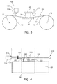
- FIG. 3 shows a schematic cross-sectional side view of the wire saw device of FIG. 2 , wherein the wire web 20 of the wire saw device is bowed.
- the wire saw device is exemplarily shown as including the wire 22 or wire web 20, which is guided by two wire guide cylinders 10 (also called “wire guides” or “pulleys”) along the wire length.
- the wire length may extend substantially parallel to the moving direction of the wire 22 or wire web 20 (indicated with arrow 24). Portions of the wire 22 may be arranged in parallel, forming the wire web 20.
- the wire 22 provided forms the wire web 20 in particular in the cutting area of the wire saw device.
- the term "wire web” can relate to the wire web 20 formed by the wire 22 between two wire guide cylinders 10. It should be understood that the wire 22 may form more than one wire web 20 which is defined as an area in which a sawing process is performed.
- the wire 22 may form multiple wire webs, for instance two wire webs both adapted for cutting a workpiece or ingot 30.
- the workpiece or ingot 30 is mounted to a table 40 configured to move against the wire 22 or wire web 20 in order to cut the ingot 30.
- the wire guide cylinders 10 are adapted to rotate in order to transport the wire 22 or wire web 20.
- the wire guide cylinders 10 can be configured to rotate at a circumferential speed (i.e., the speed at the outer circumference) of at least 5 m/s or even 10 m/s.
- the wire saw device is operated between 5 m/s and 30 m/s during operation whereas the speed may be smaller during start and stop.
- the wire saw device can in particular be operated with at least 25m/s, and can in particular be operated with about 25 m/s.
- the wire 22 or wire web 20 is decelerated from time to time in order to accelerate it in the opposite direction.
- the wire 22 or wire web 20 moves substantially along the wire length which can be a longitudinal length of the wire 22.
- the term "substantially” shall particularly embrace vibrations or the like.
- the movement can be relatively rapid in comparison to the perpendicular motion of the workpiece or ingot 30, such as a semiconductor ingot.
- the movement of the wire 22 or wire web 20 is only unidirectional, i.e., always in the forward direction.
- the movement of the wire 22 or wire web 20 may include a movement in the backward direction, in particular, the movement can be a back-and-forth movement of the wire 22 or wire web 20 in which the movement direction of the wire 22 or wire web 20 is amended repeatedly.
- the wire 22 or wire web 20 is brought into contact with the ingot 30 to cut the ingot 30, for instance, into a plurality of wafers.
- the wire 22 or wires forming the wire web 20 can be moved relative to the ingot 30, the ingot 30 can be moved relative to the wire 22 or wire web 20, or the wire 22 or wire web 20 and the ingot 30 can both be moved relative to each other.
- the ingot 30 and the wire 22 (such as the wire web 20) are pressed relatively against each other, the resulting force exerted by the ingot 30 on the wire 22 or wire web 20 causes the wire 22 or wire web 20 to become bowed.
- the orientation of the wire bow coincides with the cutting direction, and can be substantially perpendicular to the moving direction of the wire 22 or wire web 20.
- a bow height can be defined as a difference or distance along the cutting direction between a bowed state and an unbowed state of the wire 22 or wire web 20.
- the wire 22 or wire web 20 undergoes a bow due to the ingot 30 being pressed in the cutting direction. When the wire bow increases too much, it may lead to a breakage of the wire 22.
- embodiments described herein allow for the detection of a wire bow before it becomes too large, and furthermore, allow for triggering an adequate reaction in order to avoid a breakage of the wire 22.
- a reaction could be, for instance, the reduction of the speed of the ingot 30 against the wire 22 and/or an increase in the wire speed.
- Further reactions could encompass an amendment in the amount of provided slurry or the slurry composition etc.
- the wire monitoring system 100 includes a controller 140 configured to control the movement of the at least one sensor during operation of the wire saw device.
- the controller 140 is configured to move the at least one sensor periodically between a first position and a second position, wherein at least a part of the wire is positioned in a region between the first position and the second position.
- the region between the first position and the second position can include at least a part of the width of the wire web 20, and can in particular include the full width of the wire web 20.
- the distance between the first position and the second position may be equal to the width of the wire web 20, and can in particular be larger than the width of the wire web 20.
- the first positon and the second position can correspond to edge or end portions of the wire web 20, respectively.
- the moving speed of the at least one sensor is in the range of 0.005 to 1 m/s, specifically in the range of 0.01 to 0.5 m/s, and more specifically about 0.01 m/s. In some embodiments, the moving speed of the at least one sensor can be less than 0.1 m/s. As an example, between two specific points such as the first position and the second position, the moving speed of the at least one sensor can be about 0.1 m/s or even less. In some implementations, a frequency of the periodical movement between the first position and the second position is is in the range of 0.25 to 2 cycles per minutes, and specifically 0.3 to 0.5 cycles per minutes.
- the frequency can correspond to one cycle every 2 or 3 minutes.
- One cycle can be defined as one back movement and one forth movement of the at least one sensor.
- one cycle can be defined as a movement from the first position to the second position and back to the first position.
- the frequency can depend on at least one of a table speed, a material to be cut and a critical bow before wire breaking.
- the frequency can be adjustable.
- the frequency can correspond to one cycle every 2 or 3 minutes if no issues are detected, and could be increased if an issue such as a high wire bow is detected.
- the data measured and collected by the at least one sensor can be forwarded to the controller 140 where it may be further processed, such as evaluated. For instance, logic levels (i.e., 0 or 1 outcomes) of the at least one sensor may be used to monitor a progression of the wire bow.
- the controller 140 can be configured to determine whether the bow exceeds a bow threshold value. When it is determined that the bow exceeds a bow threshold value, the controller 140 can stop the operation of the wire saw device, or can increase the moving speed of the wire. Optionally or additionally, the controller 140 can reduce the speed of the workpiece against the wire or wire web.
- the bow threshold value may correspond to a predetermined value of the bow height.
- the bow threshold value may be a value that defines when the bow gets too high.
- the bow height can be defined as a difference or distance along the cutting direction between a bowed state and an unbowed state of the wire or wire web.
- FIG. 4 shows a schematic front view of a wire web 20 on a wire guide cylinder 10 and a wire monitoring system 200 according to further embodiments described herein.
- a wire monitoring system for a wire saw device includes a sensor arrangement 110 configured to be positioned adjacent to a wire or wire web 20 of the wire saw device, wherein the sensor arrangement 110 is adapted to detect a bow of the wire or wire web 20, wherein the sensor arrangement 110 includes one single sensor configured to be moved during operation of the wire saw device substantially perpendicular to a moving direction of the wire or wire web 20; and a controller configured to control the movement of the at least one sensor during operation of the wire saw device, wherein the controller is configured to move the at least one sensor periodically between a first position and a second position, wherein at least a part of the wire or wire web 20 is positioned in a region between the first position and the second position.
- a single sensor (also referred to as "bow sensor”) of the sensor arrangement 110 is moving along the holding device 120, which can be a beam frame or lateral beam frame.
- the wire monitoring system 200 includes an actuator 130 (also referred to as “motorization”) and an encoder 132 for precise positioning of the at least one sensor with respect to the wire or wire web 20.
- a reference point 210 is provided at or near the actuator 130, e.g., at a stop position.
- the reference point 210 can be a 0mm position of the at least one sensor device, e.g., with respect to the actuator 130 and/or a scale defined by the holding device 120.
- the actuator 130 and/or the encoder 132 could be configured similar to a "trancanner".
- a trancanner can for example be configured to guide the wire (e.g., unwind and rewind wire from a wire spool). It can move move forth and back e.g. along two determined positions of wire spool flanges. Here the movement can be continuous. The device can also have two determined extreme positions between which it is moving forth and back.
- the at least one sensor can be configured to detect at least one wire web position 220, and in particular a starting position ("IN”) and/or an end position ("OUT") of the wire web 20.
- the at least one sensor can be configured to automatically detect the at least one wire web position 220.
- the at least one sensor is moved back and forth (e.g., periodically) between the starting position ("IN") and the end position ("OUT") of the wire web 20.
- the starting position can be the wire web position 220 that the at least one sensor reaches first during a movement in a particular moving direction
- the end position can be the wire web position 220 that the at least one sensor reaches second or last during a movement in the particular moving direction.
- the detected wire web position can be used to stop the wire web 20 when the desired length is reached.
- the starting position ("IN") and/or the end position ("OUT") of the wire web 20 can be auto-calibrated to provide and/or convert data without time loss to modify a sensor position (e.g., if a diameter of a wire guide cylinder 10 is smaller or bigger: The diameter of the wire guide cylinder 10 can be determined when the wire guide cylinder 10 is changed).
- a specific position of the wire or wire web is reached when the sensor detects e.g. a presence of the wire or wire web. The length of the wire web is reached at this moment and the wire saw device could stop automatically.
- the situation can be similar for the wire guides: If there is a new one, the diameter is bigger.
- the used wire guide which can for example be re-grooved, are smaller.
- the sensor can be configured to measure a distance to the wire or wire web (there is no bow when the wire web is built).
- the wire monitoring system 200 can be configured for wire jump detection.
- the wire monitoring system 200 and in particular the at least one sensor, can be configured for detection of a wire jump position 240 at the wire web 20.
- the at least one sensor can move two or more times at, or above, the wire jump position 240.
- the at least one sensor can collect data related to the wire jump position 240 (e.g., each time the encoder reaches or indicates the wire jump position 240).
- the wire monitoring system 200 can provide a graph (software development) of a wire jump evolution and/or a 3D shape of the wire web 20, e.g., over time.
- the wire monitoring system 200 according to embodiments described can in particular be configured to detect wire jumps and their evolution, providing improved monitoring performance.
- a wire saw device includes a wire monitoring system.
- the wire monitoring system can be configured according to the embodiments described herein.
- FIG. 5 shows a flow chart of a method 300 for monitoring a wire in a wire saw device according to embodiments described herein.
- the method 300 includes moving at least one sensor positioned adjacent to a wire or wire web of the wire saw device during operation of the wire saw device to detect a bow of the wire and/or a wire jump (block 310).
- the method 300 determines a bow or bow height of the wire and/or whether a wire jump exists. When it is determined that the bow or bow height is below a threshold and/or that no wire jump exists, the cutting process proceeds. When it is determined that the bow or bow height is above the threshold and/or that a wire jump exists, the cutting process is stopped and/or an operator is notified.
- the moving of the sensor includes moving the sensor periodically between a first position and a second position, wherein at least a part of the wire is positioned in a region between the first position and the second position.
- the first positon and the second position can correspond to edge or end portions of the wire web, respectively.
- the method includes determining whether the bow exceeds a bow threshold value and/or whether a wire jump exists.
- the operation of the wire saw device is stopped, the moving speed of the wire is increased; a table speed is decreased; a moving table profile (e.g., the speed of the workpiece against the wire or wire web or table speed) is modified or changed, a wire cycle is modified or changed, a wire tension is modified or changed, a coolant flow is modified or changed, and a coolant pressure is modified or changed.
- the bow threshold value may correspond to a predetermined value of the bow height.
- the bow threshold value may be a value that defines when the bow gets too high.
- the bow height can be defined as a difference or distance along the cutting direction between a bowed state and an unbowed state of the wire or wire web.
- the embodiments of the present disclosure can detect a wire bow and can prevent a wire breakage due to the wire bow becoming too high. A deterioration of the cut quality and/or wafer quality can be reduced or even prevented.
- the embodiments of the present disclosure can also detect a wire jump on the web.
- the present disclosure can provide extensive information of the whole web or web bows, which cannot be obtained when using fixed sensors. By using a moving sensor, costs related to the wire monitoring system can be reduced (e.g., production costs and/or maintenance costs).
Landscapes
- Engineering & Computer Science (AREA)
- Mechanical Engineering (AREA)
- Processing Of Stones Or Stones Resemblance Materials (AREA)
- Finish Polishing, Edge Sharpening, And Grinding By Specific Grinding Devices (AREA)
Priority Applications (2)
| Application Number | Priority Date | Filing Date | Title |
|---|---|---|---|
| EP14190928.3A EP3015238A1 (de) | 2014-10-29 | 2014-10-29 | Drahtüberwachungssystem |
| CN201510090766.8A CN105984042A (zh) | 2014-10-29 | 2015-02-28 | 线监测系统、线锯装置以及用于监测线的方法 |
Applications Claiming Priority (1)
| Application Number | Priority Date | Filing Date | Title |
|---|---|---|---|
| EP14190928.3A EP3015238A1 (de) | 2014-10-29 | 2014-10-29 | Drahtüberwachungssystem |
Publications (1)
| Publication Number | Publication Date |
|---|---|
| EP3015238A1 true EP3015238A1 (de) | 2016-05-04 |
Family
ID=51870848
Family Applications (1)
| Application Number | Title | Priority Date | Filing Date |
|---|---|---|---|
| EP14190928.3A Withdrawn EP3015238A1 (de) | 2014-10-29 | 2014-10-29 | Drahtüberwachungssystem |
Country Status (2)
| Country | Link |
|---|---|
| EP (1) | EP3015238A1 (de) |
| CN (1) | CN105984042A (de) |
Cited By (4)
| Publication number | Priority date | Publication date | Assignee | Title |
|---|---|---|---|---|
| CN107866918A (zh) * | 2016-09-27 | 2018-04-03 | 松下电器产业株式会社 | 锭料的切断装置及锭料的切断装置使用的载荷检测装置 |
| CN108407116A (zh) * | 2018-03-30 | 2018-08-17 | 青岛高测科技股份有限公司 | 并线检测装置、方法及包括该并线检测装置的金刚线切片机 |
| CN113275658A (zh) * | 2020-02-19 | 2021-08-20 | 小松Ntc株式会社 | 线锯 |
| US20250033246A1 (en) * | 2022-08-31 | 2025-01-30 | Tcl Zhonghuan Renewable Energy Technology Co., Ltd. | Intelligent monitoring system and method for wire net wafering |
Families Citing this family (8)
| Publication number | Priority date | Publication date | Assignee | Title |
|---|---|---|---|---|
| CN106891451A (zh) * | 2017-02-22 | 2017-06-27 | 平凉中电科新能源技术有限公司 | 一种金刚线多线切割机断线检测方法 |
| CN106926375B (zh) * | 2017-04-25 | 2018-12-25 | 镇江仁德新能源科技有限公司 | 一种金刚石线锯在线检测装置 |
| CN107379280A (zh) * | 2017-07-03 | 2017-11-24 | 中国地质大学(北京) | 一种褐煤柱状样品的制样装置 |
| CN109557146B (zh) * | 2019-01-11 | 2024-02-13 | 南京工程学院 | 一种金刚线断线检测装置及其断线预测方法 |
| CN110550496B (zh) * | 2019-07-19 | 2021-01-12 | 许昌经纬实业有限公司 | 一种用于纺织机的进线软夹持装置 |
| CN112248247A (zh) * | 2020-10-16 | 2021-01-22 | 易忠萍 | 一种进给量自调节线锯 |
| CN117656268A (zh) * | 2022-08-31 | 2024-03-08 | 天津市环智新能源技术有限公司 | 一种监测机构及其应用、设有该监测机构的切片机 |
| CN116330504A (zh) * | 2023-02-17 | 2023-06-27 | 浙江晶盛机电股份有限公司 | 线网检测方法、线网检测装置及多线切片机 |
Citations (5)
| Publication number | Priority date | Publication date | Assignee | Title |
|---|---|---|---|---|
| WO2000047383A1 (en) * | 1999-02-12 | 2000-08-17 | Shin-Etsu Handotai Europe Limited | Apparatus and process for the slicing of monocrystalline silicon ingots |
| DE10232768A1 (de) * | 2002-07-18 | 2004-02-05 | Scanwafer Gmbh | Verfahren und Vorrichtung zur Vorschubregelung an einer Drahtsäge |
| US20100006082A1 (en) * | 2008-07-11 | 2010-01-14 | Saint-Gobain Abrasives, Inc. | Wire slicing system |
| EP2708342A1 (de) * | 2012-09-14 | 2014-03-19 | Applied Materials Switzerland Sàrl | Drahtbogenüberwachungssystem für eine Drahtsäge |
| WO2014167392A1 (en) * | 2013-04-09 | 2014-10-16 | Meyer Burger Ag | Monitoring device and method for wire web monitoring and wire saw |
Family Cites Families (2)
| Publication number | Priority date | Publication date | Assignee | Title |
|---|---|---|---|---|
| MY153330A (en) * | 2008-12-20 | 2015-01-29 | Cabot Microelectronics Corp | Wiresaw cutting method |
| CN102744796A (zh) * | 2012-06-20 | 2012-10-24 | 常州天合光能有限公司 | 硅锭切片质量监控系统及监测方法 |
-
2014
- 2014-10-29 EP EP14190928.3A patent/EP3015238A1/de not_active Withdrawn
-
2015
- 2015-02-28 CN CN201510090766.8A patent/CN105984042A/zh active Pending
Patent Citations (5)
| Publication number | Priority date | Publication date | Assignee | Title |
|---|---|---|---|---|
| WO2000047383A1 (en) * | 1999-02-12 | 2000-08-17 | Shin-Etsu Handotai Europe Limited | Apparatus and process for the slicing of monocrystalline silicon ingots |
| DE10232768A1 (de) * | 2002-07-18 | 2004-02-05 | Scanwafer Gmbh | Verfahren und Vorrichtung zur Vorschubregelung an einer Drahtsäge |
| US20100006082A1 (en) * | 2008-07-11 | 2010-01-14 | Saint-Gobain Abrasives, Inc. | Wire slicing system |
| EP2708342A1 (de) * | 2012-09-14 | 2014-03-19 | Applied Materials Switzerland Sàrl | Drahtbogenüberwachungssystem für eine Drahtsäge |
| WO2014167392A1 (en) * | 2013-04-09 | 2014-10-16 | Meyer Burger Ag | Monitoring device and method for wire web monitoring and wire saw |
Cited By (4)
| Publication number | Priority date | Publication date | Assignee | Title |
|---|---|---|---|---|
| CN107866918A (zh) * | 2016-09-27 | 2018-04-03 | 松下电器产业株式会社 | 锭料的切断装置及锭料的切断装置使用的载荷检测装置 |
| CN108407116A (zh) * | 2018-03-30 | 2018-08-17 | 青岛高测科技股份有限公司 | 并线检测装置、方法及包括该并线检测装置的金刚线切片机 |
| CN113275658A (zh) * | 2020-02-19 | 2021-08-20 | 小松Ntc株式会社 | 线锯 |
| US20250033246A1 (en) * | 2022-08-31 | 2025-01-30 | Tcl Zhonghuan Renewable Energy Technology Co., Ltd. | Intelligent monitoring system and method for wire net wafering |
Also Published As
| Publication number | Publication date |
|---|---|
| CN105984042A (zh) | 2016-10-05 |
Similar Documents
| Publication | Publication Date | Title |
|---|---|---|
| EP2708342B1 (de) | Drahtbogenüberwachungssystem für eine Drahtsäge | |
| EP2218532B1 (de) | Drahtsäge und Bedienungsverfahren dafür | |
| EP2954965A1 (de) | Verfahren und System zum Sägen eines Blocks | |
| CN105984042A (zh) | 线监测系统、线锯装置以及用于监测线的方法 | |
| EP3015237A1 (de) | Drahtüberwachungssystem | |
| EP2586582A1 (de) | Drahtsägensteuerungssystem und Drahtsäge | |
| US9969017B2 (en) | Wire saw apparatus and cut-machining method | |
| EP2777903B1 (de) | System zum blockzuführung und Verfahren dafür | |
| US10940601B2 (en) | Sample preparation saw | |
| WO2014167392A1 (en) | Monitoring device and method for wire web monitoring and wire saw | |
| JP5072204B2 (ja) | ウエーハの表面のナノトポグラフィを改善する方法及びワイヤソー装置 | |
| EP2815834A1 (de) | Drahtüberwachungssystem für eine Drahtsäge und Verfahren zur Überwachung einer Drahtsäge | |
| JP6430178B2 (ja) | ワイヤソー装置 | |
| CN105835244B (zh) | 线锯以及防止锯线脱槽的运转方法 | |
| WO2011032600A1 (en) | Method for operating a wire saw device | |
| CN203266962U (zh) | 用于切割半导体工件的线锯 | |
| CN204036679U (zh) | 丝线导向器监视装置和丝锯 | |
| EP2647458A1 (de) | Draht für Halbleiterdrahtsäge und Drahtsäge | |
| WO2012089243A1 (en) | Wire saw device, method of operating thereof | |
| EP2839912B1 (de) | Drahtsägenvorrichtung mit Sensoranordnung und Verfahren zur Überwachung des Betriebs der Drahtsägenvorrichtung | |
| KR101519245B1 (ko) | 와이어 쏘우의 절삭력 제어를 이용한 와이어 쏘잉 장치 | |
| JP5250376B2 (ja) | ワイヤ巻取り装置およびワイヤソー | |
| CN108568740B (zh) | 线状锯及线状锯的工件切断加工方法 | |
| KR20150062148A (ko) | 와이어 쏘우의 절삭력 제어 방법 및 이를 이용한 와이어 쏘잉 장치 |
Legal Events
| Date | Code | Title | Description |
|---|---|---|---|
| PUAI | Public reference made under article 153(3) epc to a published international application that has entered the european phase |
Free format text: ORIGINAL CODE: 0009012 |
|
| AK | Designated contracting states |
Kind code of ref document: A1 Designated state(s): AL AT BE BG CH CY CZ DE DK EE ES FI FR GB GR HR HU IE IS IT LI LT LU LV MC MK MT NL NO PL PT RO RS SE SI SK SM TR |
|
| AX | Request for extension of the european patent |
Extension state: BA ME |
|
| STAA | Information on the status of an ep patent application or granted ep patent |
Free format text: STATUS: THE APPLICATION IS DEEMED TO BE WITHDRAWN |
|
| 18D | Application deemed to be withdrawn |
Effective date: 20161105 |