EP3015320B1 - Rückhaltebügel zur Sicherung einer Person in einem Sitz eines Vergnügungsgeräts - Google Patents
Rückhaltebügel zur Sicherung einer Person in einem Sitz eines Vergnügungsgeräts Download PDFInfo
- Publication number
- EP3015320B1 EP3015320B1 EP14190959.8A EP14190959A EP3015320B1 EP 3015320 B1 EP3015320 B1 EP 3015320B1 EP 14190959 A EP14190959 A EP 14190959A EP 3015320 B1 EP3015320 B1 EP 3015320B1
- Authority
- EP
- European Patent Office
- Prior art keywords
- strips
- restraint bar
- skirt
- crossbar
- bar according
- Prior art date
- Legal status (The legal status is an assumption and is not a legal conclusion. Google has not performed a legal analysis and makes no representation as to the accuracy of the status listed.)
- Not-in-force
Links
- 239000000463 material Substances 0.000 claims description 12
- 210000000689 upper leg Anatomy 0.000 claims description 10
- 229920001971 elastomer Polymers 0.000 claims description 3
- 239000004033 plastic Substances 0.000 claims description 2
- 229920003023 plastic Polymers 0.000 claims description 2
- 230000003014 reinforcing effect Effects 0.000 claims description 2
- 230000003019 stabilising effect Effects 0.000 claims 3
- 239000007787 solid Substances 0.000 claims 1
- 210000002414 leg Anatomy 0.000 description 9
- 230000006378 damage Effects 0.000 description 8
- 208000027418 Wounds and injury Diseases 0.000 description 4
- 208000014674 injury Diseases 0.000 description 4
- 230000002787 reinforcement Effects 0.000 description 3
- 230000014759 maintenance of location Effects 0.000 description 2
- 210000002784 stomach Anatomy 0.000 description 2
- 229910000639 Spring steel Inorganic materials 0.000 description 1
- 230000003187 abdominal effect Effects 0.000 description 1
- 230000015572 biosynthetic process Effects 0.000 description 1
- 238000010276 construction Methods 0.000 description 1
- 238000011161 development Methods 0.000 description 1
- 230000018109 developmental process Effects 0.000 description 1
- 239000004744 fabric Substances 0.000 description 1
- 229920001821 foam rubber Polymers 0.000 description 1
- 238000005755 formation reaction Methods 0.000 description 1
- 238000003780 insertion Methods 0.000 description 1
- 230000037431 insertion Effects 0.000 description 1
- 210000003127 knee Anatomy 0.000 description 1
- 239000002184 metal Substances 0.000 description 1
- 238000000034 method Methods 0.000 description 1
- 238000007493 shaping process Methods 0.000 description 1
- 230000000087 stabilizing effect Effects 0.000 description 1
Images
Classifications
-
- B—PERFORMING OPERATIONS; TRANSPORTING
- B60—VEHICLES IN GENERAL
- B60R—VEHICLES, VEHICLE FITTINGS, OR VEHICLE PARTS, NOT OTHERWISE PROVIDED FOR
- B60R21/00—Arrangements or fittings on vehicles for protecting or preventing injuries to occupants or pedestrians in case of accidents or other traffic risks
-
- B—PERFORMING OPERATIONS; TRANSPORTING
- B60—VEHICLES IN GENERAL
- B60R—VEHICLES, VEHICLE FITTINGS, OR VEHICLE PARTS, NOT OTHERWISE PROVIDED FOR
- B60R21/00—Arrangements or fittings on vehicles for protecting or preventing injuries to occupants or pedestrians in case of accidents or other traffic risks
- B60R2021/0065—Type of vehicles
- B60R2021/0097—Amusement vehicles
Definitions
- the invention relates to a restraint bar for securing a person, in particular a child, in a seat of an amusement device or a leisure track according to the preamble of claim 1.
- the seats must have safety devices to secure people in the seats while driving.
- the safety seats in use today usually use restraint stirrups, which can be used as a stirrup over a bearing at the head end of the seat between a raised position in which the seat can be occupied or abandoned, and a lowered position in which the person in the hip area a cross bar of the restraint bar is fixed in the seat, is pivotable.
- these restraints may also include additional foot brackets that prevent the upper legs from pivoting up and down.
- Alternative security devices consist of retaining straps, which are articulated on the foot side and are tilted from the front against the person to be secured. If the restraint bar is required only as a stirrup, this can also be pivoted from the side in front of the person to be secured and then locked.
- DE 100 16 213 C1 discloses a restraint bar according to the preamble of claim 1.
- the invention has for its object to provide an improved restraint bar for securing a person, in particular a child, indicate that further complicates the disembarkation of the person from the seat with a fixed restraint bar or completely prevented.
- the invention relates to a restraint bar for securing a person, in particular a child, in a seat of an amusement device, in which the restraint bar as a tilt or swivel bar on a storage in a first position in which the seat can be occupied or abandoned, and a second position in which the person is fixed in the hip area by a cross bar of the holding bracket or a stomach strap in the seat, is pivotable.
- the transverse or abdominal bow has at least one multi-part flexible apron fastened thereto, which in the lowered position of the restraint strap can rest on the thighs of the person.
- the apron according to the invention prevents a child from being able to pull back his legs and get out of the back of such a secure seat. When the legs are pulled back, the feet would hit the apron and prevent the legs from retracting further.
- the skirt is formed of a plurality of parallel strips, which are fastened side by side on the crossbar. This prevents a child from freeing up their legs by simply lifting the free end of the skirt. For example, if more than two stripes are arranged across the legs, it is not possible for a child to lift all the stripes at the same time.
- the skirt or strips are preferably fastened to the transverse straps in the radial direction.
- the attachment can be effected in that the fastening-side ends of the skirt or the strip are inserted into a U-shaped rail which is fixed to the core or the surface of the roller-shaped cross bar.
- the mounting rail extends within a flexible sheath, z. B. of soft rubber or foam rubber, the cross bar. This will prevent the attachment of the apron or The strip may present a risk of injury or damage the clothing of the person to be secured.
- the strips or the apron may also be received in an oblique direction in a gap of the cross bar or be attached to the surface of the cross bar.
- the apron or strips are preferably each provided at their free ends with a weight plate or stabilizing plate which firmly presses on the one hand the strips or apron on the thighs of the person to be secured, and on the other hand stiffen the free ends of the skirt or strips.
- These plates may be bolted to the strip or skirt.
- the panels may also be embedded in the material of the skirt or strips to avoid damage to the person's clothing or injury from the fastening material.
- special weight plates may also be provided to stiffen the end-side free ends of the skirt or the strip by an increased thickness and / or to reinforce by weight.
- the skirt or strips are preferably made of rubbery plastic material, which may also be provided with a fabric reinforcement. This is z. B. used in conveyor belts reinforced belt material.
- the rail or strips may also consist of metal, in particular spring steel.
- the free end of the skirt or the strip on the front side can still be provided with a reinforcing element of flexible material, the front side is serrated profiled, which is the retraction of the Legs further complicated.
- preferably 3-10 parallel strips are used.
- brush rows running parallel to one another may also be used, in which the bristles are located in a flexible holding band and are directed downwards onto the thighs of the person to be secured.
- the straps are attached to the crossbar in the same way as the straps.
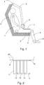
- FIG. 1 shown sketch shows a supervisory form of a passenger seat in an amusement device with a seat 2 and a back shell 3, at the upper end of a hinge 4 is arranged to pivot a restraint bar 5 pivotally between a first upper raised position and a second lower position shown.
- the restraint bar consists of a bearing in the bearing 4 retaining bar 5 with two parallel rods, between which at the lower free end a cross bar 6, which may also be formed alone as a stirrup, is fixed or pivotally mounted.
- a cross bar 6 At the bottom of the cross bar 6 is an apron or a plurality of aprons forming parallel strips 7 are attached.
- the person 1 to be secured is secured to the seat in such a way that the transverse bar 6 extends above the thighs in the lowered region of the restraint bar and is fixed in this position.
- the strips 7 are in this position on the Thighs 8 of the person up. In children, the strips 7 can also reach over the knee down to the lower leg 9 and almost to the feet 10.
- the strips 7 prevent the person to be secured can slip out of the seat to the rear and top. In the process, the strips 7 will jam when attempting to slip out between the thighs of the person and the crossbar 6 and thus prevent further retraction of the thighs. This is especially true when the cross bar 6 is an angular pivoting to z. B. 90 ° allowed.
- Fig. 2 shows a plan view of the cross bar 6 with attached strips 11 - 15. These are arranged parallel to each other, and have a small to medium distance of 1-5 cm to each other. Preferably 5 5 - 10 individual strips are distributed over the width of the cross bar. They have a length which corresponds approximately to the length of the thighs of a person to be secured or, in children, may be longer. The length and arrangement of the strips can vary with each other, so that their shape can be adapted to ergonomic requirements.
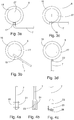
- FIGS. 3a-d Various types of attachment for attaching the strips 7 are shown on the cross bar 6.
- Fig. 3a shows an attachment of a strip 7 in a U-shaped rail 17 which is fixed axially parallel to the core 27 of the cross bar 6, wherein the fastening is effected by means of screws and the rail 17 is welded to the core 27.
- the cross bar 6 has an outer sheath 16 of, for example, soft or sponge rubber, which on the one hand represents a padding and on the other hand, the rail 17 includes, so that it can not cause injury or damage. But the legs of the rail 17 can also protrude slightly from the surface of the cross bar.
- Fig. 3b shows an attachment of the strips 7 in an oblique direction by insertion into a corresponding gap 18 of the cross bar 6.
- the cross bar 6 may be padded by a sheath 16.
- Fig. 3c shows an embodiment in which the strip 7 projects tangentially from the cross bar 6, wherein the strip by a screw 19 on the surface of the core 27 of the Cross bar 6 is attached.
- the sheath 16 is recessed at the location of the attachment 19 accordingly.
- Fig. 3d shows an attachment of the strip 7 via a hinge 20 on the surface of the cross bar 6.
- this embodiment has the same properties as the execution of Fig. 3c on.
- FIGS. 4a-c show various embodiments of the free ends of the strips 7. To increase the weight or stabilize the free ends of the strips 7 are according to Fig. 4a Weight plates 21, 22 screwed to the free ends of the strips 7.
- a corresponding weight plate 23 is embedded in the reinforced material 24 of the strip 7, so that the risk of injury or damage is reduced by fastening material in this embodiment.
- Fig. 4c shows an embodiment in which the free end-side and underside end of the strip 7 is provided with a serrated profile 26, which additionally prevents the person to be secured can move out of the seat.
- the end material 24 of the strip may be reinforced, or provided with and without weight plates 23. With sufficient strength of the material of the strip 7 at the front end can be dispensed with an increase in weight by inserted or patch weight plates.
- the serrated profiling can be formed either by appropriate shaping of the free end of the strip or screwed as an additional part to the free end of the strip.
- the profiling may also be limited to the face of the strip or the underside.
- the invention can be used not only in the upper side hinged retention straps, but in the same way hinged at the bottom retaining straps.
- the restraint bar can also be attached laterally to the seat and swiveled as a stomach bar in front of the person.
Landscapes
- Engineering & Computer Science (AREA)
- Mechanical Engineering (AREA)
- Seats For Vehicles (AREA)
Description
- Die Erfindung betrifft einen Rückhaltebügel zur Sicherung einer Person, insbesondere eines Kindes, in einem Sitz eines Vergnügungsgeräts oder einer Freizeitbahn nach dem Oberbegriff des Anspruchs 1.
- Auf Jahrmärkten und in Freizeitparks kommen vielfach Freizeitanlagen, insbesondere Vergnügungsbahnen oder sich drehende Einrichtungen zum Einsatz, bei denen sich die Personen während der Fahrt in Sitzen befinden. Die Sitze müssen Sicherungseinrichtungen aufweisen, um die Personen während der Fahrt fest in den Sitzen zu sichern. Die heutzutage zum Einsatz kommenden Sicherheitssitze verwenden in der Regel Rückhaltebügel, die als Kippbügel über eine Lagerung am kopfseitigen Ende des Sitzes zwischen einer angehobenen Stellung, in der der Sitz besetzt oder verlassen werden kann, und einer abgesenkten Stellung, in der die Person im Hüftbereich durch einen Querbügel des Rückhaltebügels im Sitz fixiert wird, verschwenkbar ist. Um zu verhindern, dass Personen, insbesondere Kinder, ihre Unterschenkel während der Fahrt anheben oder auf der Sitzfläche anwinkeln, können diese Rückhaltebügel auch zusätzliche Fußstützbügel enthalten, die das Nach-Vorne/- Obenschwenken der Unterschenkel verhindern. Alternative Sicherungseinrichtungen bestehen aus Rückhaltebügeln, die fußseitig angelenkt sind und von vorne gegen die zu sichernde Person gekippt werden. Wenn der Rückhaltebügel nur als Bauchbügel erforderlich ist, kann dieser auch von der Seite vor die zu sichernde Person geschwenkt und dann verriegelt werden.
- Obgleich derartige Rückhaltesysteme eine sichere Fixierung von Erwachsenen ermöglichen, besteht bei Kindern je nach ihrer Größe gleichwohl das Problem, dass sie sich aus dem Sicherungssystem lösen und während der Fahrt aus dem Sitz aussteigen können.
-
DE 100 16 213 C1 (D2) offenbart einen Rückhaltebügel gemäß dem Oberbegriff des Anspruchs 1. - Der Erfindung liegt die Aufgabe zugrunde, einen verbesserten Rückhaltebügel zur Sicherung einer Person, insbesondere eines Kindes, anzugeben, der das Aussteigen der Person aus dem Sitz bei fixiertem Rückhaltebügel weiter erschwert oder gänzlich verhindert.
- Diese Aufgabe wird durch die im Anspruch 1 angegebene Erfindung gelöst. Vorteilhafte Weiterbildungen der Erfindung sind in Unteransprüchen angegeben.
- Die Erfindung geht aus von einem Rückhaltebügel zur Sicherung einer Person, insbesondere eines Kindes, in einem Sitz eines Vergnügungsgeräts, bei dem der Rückhaltebügel als Kipp- oder Schwenkbügel über eine Lagerung in einer ersten Stellung, in der der Sitz besetzt oder verlassen werden kann, und einer zweiten Stellung, in der die Person im Hüftbereich durch einen Querbügel des Haltebügels oder eines Bauchbügels im Sitz fixiert wird, verschwenkbar ist.
- Erfindungsgemäß weist der Quer- oder Bauchbügel wenigstens eine daran befestigte mehrteilige flexible Schürze auf, welche in abgesenkter Stellung des Rückhaltebügels auf den Oberschenkeln der Person aufliegen kann.
- Die erfindungsgemäße Schürze verhindert, dass ein Kind seine Beine zurückziehen kann und nach hinten oben aus einem derart gesicherten Sitz aussteigen kann. Beim Zurückziehen der Beine würden die Füße gegen die Schürze stoßen und damit das weitere Zurückziehen der Beine verhindern.
- Vorzugsweise ist die Schürze aus mehreren parallel verlaufenden Streifen gebildet, die nebeneinander an dem Querbügel befestigt sind. Damit wird verhindert, dass ein Kind durch einfaches Anheben des freien Endes der Schürze einen Freiraum schafft, um die Beine zurückziehen zu können. Wenn beispielsweise quer über die Beine mehr als zwei Streifen verteilt angeordnet sind, ist es einem Kind nicht möglich, alle Streifen gleichzeitig anzuheben.
- Die Schürze bzw. Streifen sind an den Querbügeln vorzugsweise in Radialrichtung befestigt. Die Befestigung kann dadurch erfolgen, dass die befestigungsseitigen Enden der Schürze bzw. der Streifen in eine U-förmige Schiene eingesetzt sind, die an dem Kern oder der Oberfläche des walzenförmig ausgebildeten Querbügels befestigt ist. Vorzugsweise verläuft die Befestigungsschiene innerhalb einer flexiblen Ummantelung, z. B. aus Softgummi oder Moosgummi, des Querbügels. Damit wird verhindert, dass die Befestigung der Schürze oder der Streifen ein Verletzungsrisiko darstellt oder Bekleidung der zu sichernden Person beschädigen kann. Anstelle einer radialen Befestigung können die Streifen oder die Schürze auch in Schrägrichtung in einem Spalt des Querbügels aufgenommen sein oder auch an der Oberfläche des Querbügels befestigt sein.
- Es ist auch möglich, die befestigungsseitigen Enden der Streifen oder der Schürze über ein Drehgelenk an der Oberfläche des Querbügels zu befestigen. Dies erleichtert den Aufbau des Querbügels, wobei die Gelenkbefestigung zur Vermeidung einer Druckbelastung einer Person vorzugsweise an der Oberseite des Querbügels angeordnet sein sollte. Die Streifen oder Schürze verlaufen damit etwa über eine halbe Umfangslänge des Querbügels.
- Die Schürze oder die Streifen sind an ihren freien Enden vorzugsweise jeweils mit einer Gewichtsplatte oder Stabilisierungsplatte versehen, die einerseits die Streifen oder die Schürze fest auf die Oberschenkel der zu sichernden Person drücken, und andererseits die freien Enden der Schürze oder der Streifen versteifen. Diese Platten können an den Streifen oder der Schürze verschraubt sein. Die Platten können auch in das Material der Schürze oder der Streifen eingebettet sein, um Beschädigungen der Bekleidung der Person oder Verletzungen durch das Befestigungsmaterial zu vermeiden. Anstelle von speziellen Gewichtsplatten kann auch vorgesehen sein, die endseitigen freien Enden der Schürze oder der Streifen durch eine vergrößerte Dicke zu versteifen und/oder gewichtsmäßig zu verstärken.
- Die Schürze oder die Streifen bestehen vorzugsweise aus gummiartigem Kunststoffmaterial, welches auch mit einer Gewebeverstärkung versehen sein kann. Hierzu eignet sich z. B. ein bei Förderbändern verwendetes armiertes Gurtmaterial. Die Schiene oder die Streifen können auch aus Metall, insbesondere Federstahl, bestehen.
- Zur weiteren Erhöhung der Sicherheit gegen Herausschlüpfen einer Person, insbesondere eines Kindes, aus dem Sitz kann das freie Ende der Schürze oder der Streifen an der Stirnseite jeweils noch mit einem Verstärkungselement aus flexiblem Material versehen sein, das vorderseitig zackenartig profiliert ist, welches das Zurückziehen der Beine weiter erschwert.
- Bei der Erfindung werden vorzugsweise 3 - 10 parallele Streifen verwendet. Alternativ können auch parallel zueinander verlaufende Bürstenreihen verwendet werden, bei denen sich die Borsten in einem flexiblen Halteband befinden und nach unten auf die Oberschenkel der zu sichernden Person gerichtet sind. Die Haltebänder sind in gleicher Weise wie die Streifen an dem Querbügel befestigt.
- Die Erfindung wird nachstehend anhand eines Ausführungsbeispiels näher erläutert. Es zeigen:
- Fig. 1
- eine schematische Seitenansicht eines Sitzes einer Ausführungsform eines Vergnügungsgeräts nach der Erfindung,
- Fig. 2
- eine Aufsicht auf einen Querbügel mit angesetzten Streifen,
- Fig. 3 a-d
- Befestigungsarten zur Befestigung von Streifen an dem Querbügel, und
- Fig. 4 a-c
- Ausbildungen der freien Enden der Streifen.
- Die in
Fig. 1 gezeigte Skizze zeigt eine Aufsichtsform eines Personensitzes in einem Vergnügungsgerät mit einer Sitzschale 2 und einer Rückenschale 3, an deren oberem Ende ein Gelenk 4 angeordnet ist, um einen Rückhaltebügel 5 schwenkbar zwischen einer ersten oberen angehobenen Stellung und einer zweiten unteren dargestellten Stellung verschwenken zu können. Der Rückhaltebügel besteht aus einem im Lager 4 gelagerten Rückhaltebügel 5 mit zwei parallelen Stangen, zwischen denen am unteren freien Ende ein Querbügel 6, der auch allein als Bauchbügel ausgebildet sein kann, fest oder schwenkbar befestigt ist. An der Unterseite des Querbügels 6 ist eine Schürze bzw. es sind mehrere eine Schürze bildende parallele Streifen 7 befestigt. - Die zu sichernde Person 1 ist auf dem Sitz derart gesichert, dass der Querbügel 6 in abgesenkter Stellung des Rückhaltebügels im Hüftbereich oberhalb der Oberschenkel verläuft und in dieser Stellung fixiert ist. Die Streifen 7 liegen in dieser Stellung auf den Oberschenkeln 8 der Person auf. Bei Kindern können die Streifen 7 auch noch über die Knie bis auf die Unterschenkel 9 und fast bis zu den Füßen 10 heranreichen.
- Die Streifen 7 verhindern, dass die zu sichernde Person nach hinten und oben aus dem Sitz herausschlüpfen kann. Dabei werden sich die Streifen 7 beim Versuch des Herausschlüpfens zwischen den Oberschenkeln der Person und dem Querbügel 6 verklemmen und damit das weitere Zurückziehen der Oberschenkel verhindern. Dies gilt insbesondere auch dann, wenn der Querbügel 6 eine winkelmäßige Verschwenkung um z. B. 90° erlaubt.
-
Fig. 2 zeigt eine Aufsicht auf den Querbügel 6 mit daran befestigten Streifen 11 - 15. Diese sind parallel zueinander angeordnet, und weisen einen kleinen bis mittleren Abstand von 1-5 cm zueinander auf. Vorzugsweise sind über die Breite des Querbügels 6 5 - 10 einzelne Streifen verteilt angeordnet. Sie weisen eine Länge auf, die etwa der Länge der Oberschenkel einer zu sichernden Person entspricht oder auch, bei Kindern, länger sein kann. Die Länge und Anordnung der Streifen kann untereinander variieren, so dass ihre Form ergonomischen Vorgaben angepasst werden kann. - In den
Figuren 3a - d sind verschiedene Befestigungsarten zur Befestigung der Streifen 7 an dem Querbügel 6 dargestellt.Fig. 3a zeigt eine Befestigung eines Streifens 7 in einer U-förmigen Schiene 17, die achsparallel am Kern 27 des Querbügels 6 befestigt ist, wobei die Befestigung mittels Schrauben erfolgt und die Schiene 17 am Kern 27 verschweißt ist. Der Querbügel 6 weist eine außenseitige Ummantelung 16 aus beispielsweise Soft- oder Moosgummi auf, die einerseits eine Polsterung darstellt und andererseits die Schiene 17 einschließt, so dass diese keine Verletzungen oder Schäden verursachen kann. Die Schenkel der Schiene 17 können aber auch etwas von der Oberfläche des Querbügels vorstehen. -
Fig. 3b zeigt eine Befestigung der Streifen 7 in Schrägrichtung durch Einsetzen in einen entsprechenden Spalt 18 des Querbügels 6. Auch hier kann der Querbügel 6 durch eine Ummantelung 16 abgepolstert sein. -
Fig. 3c zeigt eine Ausbildung, bei der der Streifen 7 tangential von dem Querbügel 6 absteht, wobei der Streifen durch eine Schraubverbindung 19 an der Oberfläche des Kerns 27 des Querbügels 6 befestigt ist. Die Ummantelung 16 ist an der Stelle der Befestigung 19 entsprechend ausgespart. -
Fig. 3d zeigt eine Befestigung des Streifens 7 über ein Gelenk 20 an der Oberfläche des Querbügels 6. Beim Verschwenken der Streifen 7 bis in die Tangentiale zur Oberfläche des Querbügels 6 weist diese Ausführung die gleichen Eigenschaften wie die Ausführung vonFig. 3c auf. - Die
Figuren 4a - c zeigen verschiedene Ausbildungen der freien Enden der Streifen 7. Zur Gewichtserhöhung oder Stabilisierung der freien Enden der Streifen 7 sind gemäßFig. 4a Gewichtsplatten 21, 22 an die freien Enden der Streifen 7 angeschraubt. - Gemäß
Fig. 4b ist alternativ eine entsprechende Gewichtsplatte 23 in das verstärkte Material 24 des Streifens 7 eingebettet, so dass die Verletzungs- oder Beschädigungsgefahr durch Befestigungsmaterial bei dieser Ausführung verringert ist. -
Fig. 4c zeigt eine Ausbildungsform, bei der das freie stirnseitige und unterseitige Ende des Streifens 7 mit einer zackenförmigen Profilierung 26 versehen ist, die es zusätzlich verhindert, dass die zu sichernde Person sich aus dem Sitz herausbewegen kann. Das endseitige Material 24 des Streifens kann verstärkt, oder mit und ohne Gewichtsplatten 23 versehen sein. Bei ausreichender Stärke des Materials der Streifen 7 am stirnseitigen Ende kann auf eine Gewichtserhöhung durch eingelegte oder aufgesetzte Gewichtsplatten verzichtet werden. - Die zackenartige Profilierung kann entweder durch entsprechende Ausformung des freien Endes der Streifen gebildet sein oder als zusätzliches Teil an das freie Ende der Streifen angeschraubt sein. Die Profilierung kann sich auch auf die Stirnseite des Streifens oder die Unterseite beschränken.
- Die Erfindung lässt sich nicht nur bei oberseitig angelenkten Rückhaltebügeln verwenden, sondern in gleicher Weise bei unterseitig angelenkten Rückhaltebügeln.
- Ferner kann der Rückhaltebügel auch seitlich am Sitz befestigt sein und als Bauchbügel vor die Person geschwenkt werden.
-
- 1
- Person
- 2
- Sitzschale
- 3
- Rückenschale
- 4
- Gelenk
- 5
- Rückhaltebügel
- 6
- Querbügel
- 7
- Streifen, Schürze
- 8
- Oberschenkel
- 9
- Unterschenkel
- 10
- Füße
- 11-15
- Streifen
- 16
- Ummantelung
- 17
- Schiene
- 18
- Spalt
- 19
- Schraubbefestigung
- 20
- Gelenk
- 21, 22
- Gewichtsplatten
- 23
- Gewichtsplatte
- 24
- Verstärkung
- 25
- Verstärkung
- 26
- Profilierung
- 27
- Kern
Claims (12)
- Rückhaltebügel zur Sicherung einer Person (1), insbesondere eines Kindes, in einem Sitz eines Vergnügungsgerätes, bei dem der Rückhaltebügel (5) über ein an dem Sitz befestigten Gelenk (4) zwischen einer ersten Stellung, in der der Sitz besetzt oder verlassen werden kann, und einer zweiten Stellung, in der die Person (1) im Hüftbereich durch einen Querbügel (6) des Rückhaltebügels im Sitz fixiert wird, verschwenkbar ist, dadurch gekennzeichnet, dass der Querbügel (6) wenigstens eine daran befestigte mehrteilige flexible Schürze (7) aufweist, welche in der zweiten Stellung des Rückhaltebügels (5) auf den Oberschenkeln (8) der Person (1) aufliegen kann.
- Rückhaltebügel nach Anspruch 1, dadurch gekennzeichnet, dass die Schürze (7) aus einer Reihe parallel verlaufender voneinander getrennter Streifen gebildet ist, die nebeneinander an dem Querbügel (6) befestigt sind.
- Rückhaltebügel nach Anspruch 2, dadurch gekennzeichnet, dass die Streifen (7) in Radial-, Schräg- oder Tangentialrichtung von der Oberfläche des Querbügels abstehend verlaufen, wobei die befestigungsseitigen Enden der Streifen an dem Querbügel (6) befestigt sind.
- Rückhaltebügel nach Anspruch 2, dadurch gekennzeichnet, dass die befestigungsseitigen Enden der Streifen oder die Schürze an dem Querbügel gelenkig (20) befestigt sind.
- Rückhaltebügel nach einem oder mehreren der vorhergehenden Ansprüche, dadurch gekennzeichnet, dass der Querbügel (6) walzenförmig mit einem festen Kern (27) und einer flexiblen Ummantelung (16) ausgebildet ist.
- Rückhaltebügel nach Anspruch 5, dadurch gekennzeichnet, dass die Schürze oder die Streifen (7) in einer U-förmigen Schiene (17) aufgenommen sind, welche in Achsialrichtung am Kern des Querbügels (6) innerhalb der flexiblen Ummantelung (16) befestigt ist.
- Rückhaltebügel nach Anspruch 1 oder 2, dadurch gekennzeichnet, dass die Schürze oder die Streifen (7) an ihren freien Enden mit einer Gewichts- oder Stabilisierungsplatte (21- 23) versehen ist oder sind.
- Rückhaltebügel nach Anspruch 7, dadurch gekennzeichnet, dass die Gewichts- oder Stabilisierungsplatte (21 - 23) eine Länge von 1/3 bis 2/3 der Gesamtlänge der Schürze oder der Streifen (7) aufweist.
- Rückhaltebügel nach Anspruch 7, dadurch gekennzeichnet, dass die Gewichts- oder Stabilisierungsplatte (23) in das Material der Schürze oder der Streifen (7) eingebettet ist.
- Rückhaltbügel nach einem oder mehreren der vorhergehenden Ansprüche, dadurch gekennzeichnet, dass die Schürze oder die Streifen (7) aus Gummi oder gummiartigem Kunststoffmaterial besteht.
- Rückhaltebügel nach Anspruch 1 oder 2, dadurch gekennzeichnet, dass die Schürze oder die Streifen am freien Ende ein vorder- und/oder unterseitig profiliertes Verstärkungselement (26) aus flexiblem Material aufweisen.
- Rückhaltebügel nach Anspruch 1, dadurch gekennzeichnet, dass der Querbügel um seine Achse verschwenkbar ist.
Priority Applications (2)
| Application Number | Priority Date | Filing Date | Title |
|---|---|---|---|
| EP14190959.8A EP3015320B1 (de) | 2014-10-29 | 2014-10-29 | Rückhaltebügel zur Sicherung einer Person in einem Sitz eines Vergnügungsgeräts |
| PCT/EP2015/074836 WO2016066627A1 (de) | 2014-10-29 | 2015-10-27 | Rückhaltebügel zur sicherung einer person in einem sitz eines vergnügungsgeräts |
Applications Claiming Priority (1)
| Application Number | Priority Date | Filing Date | Title |
|---|---|---|---|
| EP14190959.8A EP3015320B1 (de) | 2014-10-29 | 2014-10-29 | Rückhaltebügel zur Sicherung einer Person in einem Sitz eines Vergnügungsgeräts |
Publications (2)
| Publication Number | Publication Date |
|---|---|
| EP3015320A1 EP3015320A1 (de) | 2016-05-04 |
| EP3015320B1 true EP3015320B1 (de) | 2017-08-09 |
Family
ID=51844555
Family Applications (1)
| Application Number | Title | Priority Date | Filing Date |
|---|---|---|---|
| EP14190959.8A Not-in-force EP3015320B1 (de) | 2014-10-29 | 2014-10-29 | Rückhaltebügel zur Sicherung einer Person in einem Sitz eines Vergnügungsgeräts |
Country Status (2)
| Country | Link |
|---|---|
| EP (1) | EP3015320B1 (de) |
| WO (1) | WO2016066627A1 (de) |
Citations (1)
| Publication number | Priority date | Publication date | Assignee | Title |
|---|---|---|---|---|
| DE10016213C1 (de) * | 2000-03-31 | 2001-10-25 | Fab S A R L Freizeit Anlagen B | Rückhaltebügel zur Sicherung einer Person in Fahrzeugen, insbesondere für Vergnügungsbahnen |
Family Cites Families (1)
| Publication number | Priority date | Publication date | Assignee | Title |
|---|---|---|---|---|
| US7654613B2 (en) * | 2008-01-14 | 2010-02-02 | Eric Bass | Head and body protection system for a child safety seat |
-
2014
- 2014-10-29 EP EP14190959.8A patent/EP3015320B1/de not_active Not-in-force
-
2015
- 2015-10-27 WO PCT/EP2015/074836 patent/WO2016066627A1/de not_active Ceased
Patent Citations (1)
| Publication number | Priority date | Publication date | Assignee | Title |
|---|---|---|---|---|
| DE10016213C1 (de) * | 2000-03-31 | 2001-10-25 | Fab S A R L Freizeit Anlagen B | Rückhaltebügel zur Sicherung einer Person in Fahrzeugen, insbesondere für Vergnügungsbahnen |
Also Published As
| Publication number | Publication date |
|---|---|
| EP3015320A1 (de) | 2016-05-04 |
| WO2016066627A1 (de) | 2016-05-06 |
Similar Documents
| Publication | Publication Date | Title |
|---|---|---|
| EP0043983B1 (de) | Krankentrage | |
| DE2212811C3 (de) | Transportvorrichtung für human- oder tiermedizinische Zwecke | |
| EP2174852B1 (de) | Sessel fur Sessellift | |
| DE19960517A1 (de) | Massagevorrichtung | |
| DE3315929A1 (de) | Schwerkraftstreckapparat | |
| DE60033041T2 (de) | Stütz- und Haltestruktur für die Fahrgäste eines öffentlichen Transportfahrzeugs | |
| EP0151221A2 (de) | Behinderten-Ski | |
| EP2114325B1 (de) | Vorrichtung zum entlasten und therapieren der cervicalen wirbelsäule | |
| EP0002188B1 (de) | Laufbandvorrichtung für Therapie und Rehabilitation von Gehbehinderten | |
| DE102013215063B4 (de) | Innenausstattungsgegenstand zur Anordnung in Fahrzeugen des öffentlichen Verkehrs | |
| EP0073272A2 (de) | Krankentrage mit Sicherheitsgurt-System | |
| EP1721801B1 (de) | Einrichtung zum Schutz der Fahrgäste auf dem Sessel eines Sesselliftes | |
| EP3015320B1 (de) | Rückhaltebügel zur Sicherung einer Person in einem Sitz eines Vergnügungsgeräts | |
| DE69721571T2 (de) | Verbesserungen für einen stuhl | |
| EP3875068B1 (de) | Bergungsvorrichtung | |
| DE20213310U1 (de) | Rückhaltesystem | |
| DE20016319U1 (de) | Krankentrage mit Patienten-Rückhaltesystem für liegende Personen | |
| DE202013104491U1 (de) | Trainer mit einem suspendierten Sattel | |
| DE102007023371B4 (de) | Fahrzeugsitz mit verschiebbaren Querstreben und Kraftfahrzeug mit einem solchen Fahrzeugsitz | |
| DE20023065U1 (de) | Rettungstuch zur schnellen Evakuierung von bettlägerigen Personen | |
| DE20106036U1 (de) | Rückhaltesystem in Behindertentransportkraftwagen | |
| DE9311021U1 (de) | Vorrichtung zum Halten des Rollstuhls von behinderten Personen in Kraftfahrzeugen | |
| DE102006008256B9 (de) | Schleppbügel für einen Schlepplift | |
| DE102011109859A1 (de) | Spineboard | |
| DE102009038838B4 (de) | Crashrettungsvorrichtung zur Anbringung an einer Schleiftrage |
Legal Events
| Date | Code | Title | Description |
|---|---|---|---|
| PUAI | Public reference made under article 153(3) epc to a published international application that has entered the european phase |
Free format text: ORIGINAL CODE: 0009012 |
|
| AK | Designated contracting states |
Kind code of ref document: A1 Designated state(s): AL AT BE BG CH CY CZ DE DK EE ES FI FR GB GR HR HU IE IS IT LI LT LU LV MC MK MT NL NO PL PT RO RS SE SI SK SM TR |
|
| AX | Request for extension of the european patent |
Extension state: BA ME |
|
| 17P | Request for examination filed |
Effective date: 20160614 |
|
| RBV | Designated contracting states (corrected) |
Designated state(s): AL AT BE BG CH CY CZ DE DK EE ES FI FR GB GR HR HU IE IS IT LI LT LU LV MC MK MT NL NO PL PT RO RS SE SI SK SM TR |
|
| GRAP | Despatch of communication of intention to grant a patent |
Free format text: ORIGINAL CODE: EPIDOSNIGR1 |
|
| INTG | Intention to grant announced |
Effective date: 20170321 |
|
| GRAS | Grant fee paid |
Free format text: ORIGINAL CODE: EPIDOSNIGR3 |
|
| GRAA | (expected) grant |
Free format text: ORIGINAL CODE: 0009210 |
|
| AK | Designated contracting states |
Kind code of ref document: B1 Designated state(s): AL AT BE BG CH CY CZ DE DK EE ES FI FR GB GR HR HU IE IS IT LI LT LU LV MC MK MT NL NO PL PT RO RS SE SI SK SM TR |
|
| REG | Reference to a national code |
Ref country code: GB Ref legal event code: FG4D Free format text: NOT ENGLISH |
|
| REG | Reference to a national code |
Ref country code: CH Ref legal event code: EP Ref country code: AT Ref legal event code: REF Ref document number: 916430 Country of ref document: AT Kind code of ref document: T Effective date: 20170815 |
|
| REG | Reference to a national code |
Ref country code: IE Ref legal event code: FG4D Free format text: LANGUAGE OF EP DOCUMENT: GERMAN |
|
| REG | Reference to a national code |
Ref country code: DE Ref legal event code: R096 Ref document number: 502014004905 Country of ref document: DE |
|
| REG | Reference to a national code |
Ref country code: FR Ref legal event code: PLFP Year of fee payment: 4 |
|
| REG | Reference to a national code |
Ref country code: NL Ref legal event code: MP Effective date: 20170809 |
|
| REG | Reference to a national code |
Ref country code: LT Ref legal event code: MG4D |
|
| PG25 | Lapsed in a contracting state [announced via postgrant information from national office to epo] |
Ref country code: FI Free format text: LAPSE BECAUSE OF FAILURE TO SUBMIT A TRANSLATION OF THE DESCRIPTION OR TO PAY THE FEE WITHIN THE PRESCRIBED TIME-LIMIT Effective date: 20170809 Ref country code: SE Free format text: LAPSE BECAUSE OF FAILURE TO SUBMIT A TRANSLATION OF THE DESCRIPTION OR TO PAY THE FEE WITHIN THE PRESCRIBED TIME-LIMIT Effective date: 20170809 Ref country code: HR Free format text: LAPSE BECAUSE OF FAILURE TO SUBMIT A TRANSLATION OF THE DESCRIPTION OR TO PAY THE FEE WITHIN THE PRESCRIBED TIME-LIMIT Effective date: 20170809 Ref country code: LT Free format text: LAPSE BECAUSE OF FAILURE TO SUBMIT A TRANSLATION OF THE DESCRIPTION OR TO PAY THE FEE WITHIN THE PRESCRIBED TIME-LIMIT Effective date: 20170809 Ref country code: NO Free format text: LAPSE BECAUSE OF FAILURE TO SUBMIT A TRANSLATION OF THE DESCRIPTION OR TO PAY THE FEE WITHIN THE PRESCRIBED TIME-LIMIT Effective date: 20171109 Ref country code: NL Free format text: LAPSE BECAUSE OF FAILURE TO SUBMIT A TRANSLATION OF THE DESCRIPTION OR TO PAY THE FEE WITHIN THE PRESCRIBED TIME-LIMIT Effective date: 20170809 |
|
| PGFP | Annual fee paid to national office [announced via postgrant information from national office to epo] |
Ref country code: DE Payment date: 20171130 Year of fee payment: 4 |
|
| PG25 | Lapsed in a contracting state [announced via postgrant information from national office to epo] |
Ref country code: LV Free format text: LAPSE BECAUSE OF FAILURE TO SUBMIT A TRANSLATION OF THE DESCRIPTION OR TO PAY THE FEE WITHIN THE PRESCRIBED TIME-LIMIT Effective date: 20170809 Ref country code: PL Free format text: LAPSE BECAUSE OF FAILURE TO SUBMIT A TRANSLATION OF THE DESCRIPTION OR TO PAY THE FEE WITHIN THE PRESCRIBED TIME-LIMIT Effective date: 20170809 Ref country code: IS Free format text: LAPSE BECAUSE OF FAILURE TO SUBMIT A TRANSLATION OF THE DESCRIPTION OR TO PAY THE FEE WITHIN THE PRESCRIBED TIME-LIMIT Effective date: 20171209 Ref country code: RS Free format text: LAPSE BECAUSE OF FAILURE TO SUBMIT A TRANSLATION OF THE DESCRIPTION OR TO PAY THE FEE WITHIN THE PRESCRIBED TIME-LIMIT Effective date: 20170809 Ref country code: GR Free format text: LAPSE BECAUSE OF FAILURE TO SUBMIT A TRANSLATION OF THE DESCRIPTION OR TO PAY THE FEE WITHIN THE PRESCRIBED TIME-LIMIT Effective date: 20171110 Ref country code: BG Free format text: LAPSE BECAUSE OF FAILURE TO SUBMIT A TRANSLATION OF THE DESCRIPTION OR TO PAY THE FEE WITHIN THE PRESCRIBED TIME-LIMIT Effective date: 20171109 Ref country code: ES Free format text: LAPSE BECAUSE OF FAILURE TO SUBMIT A TRANSLATION OF THE DESCRIPTION OR TO PAY THE FEE WITHIN THE PRESCRIBED TIME-LIMIT Effective date: 20170809 |
|
| PG25 | Lapsed in a contracting state [announced via postgrant information from national office to epo] |
Ref country code: DK Free format text: LAPSE BECAUSE OF FAILURE TO SUBMIT A TRANSLATION OF THE DESCRIPTION OR TO PAY THE FEE WITHIN THE PRESCRIBED TIME-LIMIT Effective date: 20170809 Ref country code: CZ Free format text: LAPSE BECAUSE OF FAILURE TO SUBMIT A TRANSLATION OF THE DESCRIPTION OR TO PAY THE FEE WITHIN THE PRESCRIBED TIME-LIMIT Effective date: 20170809 Ref country code: RO Free format text: LAPSE BECAUSE OF FAILURE TO SUBMIT A TRANSLATION OF THE DESCRIPTION OR TO PAY THE FEE WITHIN THE PRESCRIBED TIME-LIMIT Effective date: 20170809 |
|
| REG | Reference to a national code |
Ref country code: DE Ref legal event code: R097 Ref document number: 502014004905 Country of ref document: DE |
|
| PG25 | Lapsed in a contracting state [announced via postgrant information from national office to epo] |
Ref country code: SK Free format text: LAPSE BECAUSE OF FAILURE TO SUBMIT A TRANSLATION OF THE DESCRIPTION OR TO PAY THE FEE WITHIN THE PRESCRIBED TIME-LIMIT Effective date: 20170809 Ref country code: MC Free format text: LAPSE BECAUSE OF FAILURE TO SUBMIT A TRANSLATION OF THE DESCRIPTION OR TO PAY THE FEE WITHIN THE PRESCRIBED TIME-LIMIT Effective date: 20170809 Ref country code: EE Free format text: LAPSE BECAUSE OF FAILURE TO SUBMIT A TRANSLATION OF THE DESCRIPTION OR TO PAY THE FEE WITHIN THE PRESCRIBED TIME-LIMIT Effective date: 20170809 Ref country code: SM Free format text: LAPSE BECAUSE OF FAILURE TO SUBMIT A TRANSLATION OF THE DESCRIPTION OR TO PAY THE FEE WITHIN THE PRESCRIBED TIME-LIMIT Effective date: 20170809 Ref country code: IT Free format text: LAPSE BECAUSE OF FAILURE TO SUBMIT A TRANSLATION OF THE DESCRIPTION OR TO PAY THE FEE WITHIN THE PRESCRIBED TIME-LIMIT Effective date: 20170809 |
|
| PLBE | No opposition filed within time limit |
Free format text: ORIGINAL CODE: 0009261 |
|
| STAA | Information on the status of an ep patent application or granted ep patent |
Free format text: STATUS: NO OPPOSITION FILED WITHIN TIME LIMIT |
|
| 26N | No opposition filed |
Effective date: 20180511 |
|
| REG | Reference to a national code |
Ref country code: IE Ref legal event code: MM4A |
|
| PG25 | Lapsed in a contracting state [announced via postgrant information from national office to epo] |
Ref country code: LU Free format text: LAPSE BECAUSE OF NON-PAYMENT OF DUE FEES Effective date: 20171029 |
|
| REG | Reference to a national code |
Ref country code: BE Ref legal event code: MM Effective date: 20171031 |
|
| PG25 | Lapsed in a contracting state [announced via postgrant information from national office to epo] |
Ref country code: SI Free format text: LAPSE BECAUSE OF FAILURE TO SUBMIT A TRANSLATION OF THE DESCRIPTION OR TO PAY THE FEE WITHIN THE PRESCRIBED TIME-LIMIT Effective date: 20170809 Ref country code: BE Free format text: LAPSE BECAUSE OF NON-PAYMENT OF DUE FEES Effective date: 20171031 |
|
| PG25 | Lapsed in a contracting state [announced via postgrant information from national office to epo] |
Ref country code: MT Free format text: LAPSE BECAUSE OF FAILURE TO SUBMIT A TRANSLATION OF THE DESCRIPTION OR TO PAY THE FEE WITHIN THE PRESCRIBED TIME-LIMIT Effective date: 20170809 |
|
| REG | Reference to a national code |
Ref country code: FR Ref legal event code: PLFP Year of fee payment: 5 |
|
| PG25 | Lapsed in a contracting state [announced via postgrant information from national office to epo] |
Ref country code: IE Free format text: LAPSE BECAUSE OF NON-PAYMENT OF DUE FEES Effective date: 20171029 |
|
| PGFP | Annual fee paid to national office [announced via postgrant information from national office to epo] |
Ref country code: FR Payment date: 20181023 Year of fee payment: 5 Ref country code: CH Payment date: 20181019 Year of fee payment: 5 |
|
| REG | Reference to a national code |
Ref country code: DE Ref legal event code: R119 Ref document number: 502014004905 Country of ref document: DE |
|
| GBPC | Gb: european patent ceased through non-payment of renewal fee |
Effective date: 20181029 |
|
| PG25 | Lapsed in a contracting state [announced via postgrant information from national office to epo] |
Ref country code: HU Free format text: LAPSE BECAUSE OF FAILURE TO SUBMIT A TRANSLATION OF THE DESCRIPTION OR TO PAY THE FEE WITHIN THE PRESCRIBED TIME-LIMIT; INVALID AB INITIO Effective date: 20141029 |
|
| PG25 | Lapsed in a contracting state [announced via postgrant information from national office to epo] |
Ref country code: DE Free format text: LAPSE BECAUSE OF NON-PAYMENT OF DUE FEES Effective date: 20190501 |
|
| PG25 | Lapsed in a contracting state [announced via postgrant information from national office to epo] |
Ref country code: GB Free format text: LAPSE BECAUSE OF NON-PAYMENT OF DUE FEES Effective date: 20181029 Ref country code: CY Free format text: LAPSE BECAUSE OF FAILURE TO SUBMIT A TRANSLATION OF THE DESCRIPTION OR TO PAY THE FEE WITHIN THE PRESCRIBED TIME-LIMIT Effective date: 20170809 |
|
| PG25 | Lapsed in a contracting state [announced via postgrant information from national office to epo] |
Ref country code: MK Free format text: LAPSE BECAUSE OF FAILURE TO SUBMIT A TRANSLATION OF THE DESCRIPTION OR TO PAY THE FEE WITHIN THE PRESCRIBED TIME-LIMIT Effective date: 20170809 |
|
| PG25 | Lapsed in a contracting state [announced via postgrant information from national office to epo] |
Ref country code: TR Free format text: LAPSE BECAUSE OF FAILURE TO SUBMIT A TRANSLATION OF THE DESCRIPTION OR TO PAY THE FEE WITHIN THE PRESCRIBED TIME-LIMIT Effective date: 20170809 |
|
| PG25 | Lapsed in a contracting state [announced via postgrant information from national office to epo] |
Ref country code: PT Free format text: LAPSE BECAUSE OF FAILURE TO SUBMIT A TRANSLATION OF THE DESCRIPTION OR TO PAY THE FEE WITHIN THE PRESCRIBED TIME-LIMIT Effective date: 20170809 |
|
| REG | Reference to a national code |
Ref country code: CH Ref legal event code: PL |
|
| PG25 | Lapsed in a contracting state [announced via postgrant information from national office to epo] |
Ref country code: LI Free format text: LAPSE BECAUSE OF NON-PAYMENT OF DUE FEES Effective date: 20191031 Ref country code: AL Free format text: LAPSE BECAUSE OF FAILURE TO SUBMIT A TRANSLATION OF THE DESCRIPTION OR TO PAY THE FEE WITHIN THE PRESCRIBED TIME-LIMIT Effective date: 20170809 Ref country code: CH Free format text: LAPSE BECAUSE OF NON-PAYMENT OF DUE FEES Effective date: 20191031 |
|
| PG25 | Lapsed in a contracting state [announced via postgrant information from national office to epo] |
Ref country code: FR Free format text: LAPSE BECAUSE OF NON-PAYMENT OF DUE FEES Effective date: 20191031 |
|
| REG | Reference to a national code |
Ref country code: AT Ref legal event code: MM01 Ref document number: 916430 Country of ref document: AT Kind code of ref document: T Effective date: 20191029 |
|
| PG25 | Lapsed in a contracting state [announced via postgrant information from national office to epo] |
Ref country code: AT Free format text: LAPSE BECAUSE OF NON-PAYMENT OF DUE FEES Effective date: 20191029 |