EP3015401B1 - Entrepôt automatique et son procédé de fonctionnement - Google Patents
Entrepôt automatique et son procédé de fonctionnement Download PDFInfo
- Publication number
- EP3015401B1 EP3015401B1 EP14818090.4A EP14818090A EP3015401B1 EP 3015401 B1 EP3015401 B1 EP 3015401B1 EP 14818090 A EP14818090 A EP 14818090A EP 3015401 B1 EP3015401 B1 EP 3015401B1
- Authority
- EP
- European Patent Office
- Prior art keywords
- traveling
- stacker crane
- mast
- drive wheel
- unit
- Prior art date
- Legal status (The legal status is an assumption and is not a legal conclusion. Google has not performed a legal analysis and makes no representation as to the accuracy of the status listed.)
- Active
Links
Images




Classifications
-
- B—PERFORMING OPERATIONS; TRANSPORTING
- B65—CONVEYING; PACKING; STORING; HANDLING THIN OR FILAMENTARY MATERIAL
- B65G—TRANSPORT OR STORAGE DEVICES, e.g. CONVEYORS FOR LOADING OR TIPPING, SHOP CONVEYOR SYSTEMS OR PNEUMATIC TUBE CONVEYORS
- B65G1/00—Storing articles, individually or in orderly arrangement, in warehouses or magazines
- B65G1/02—Storage devices
- B65G1/04—Storage devices mechanical
- B65G1/0407—Storage devices mechanical using stacker cranes
-
- B—PERFORMING OPERATIONS; TRANSPORTING
- B66—HOISTING; LIFTING; HAULING
- B66F—HOISTING, LIFTING, HAULING OR PUSHING, NOT OTHERWISE PROVIDED FOR, e.g. DEVICES WHICH APPLY A LIFTING OR PUSHING FORCE DIRECTLY TO THE SURFACE OF A LOAD
- B66F9/00—Devices for lifting or lowering bulky or heavy goods for loading or unloading purposes
- B66F9/06—Devices for lifting or lowering bulky or heavy goods for loading or unloading purposes movable, with their loads, on wheels or the like, e.g. fork-lift trucks
- B66F9/07—Floor-to-roof stacking devices, e.g. "stacker cranes", "retrievers"
- B66F9/072—Travelling gear therefor
Definitions
- the present invention relates to an automated warehouse for storing articles and an operation method for the same.
- an automated warehouse including a stacker crane configured to convey articles has been known (see Patent Literature 1, for example).
- a stacker crane travels along a plurality of shelves and conveys articles between a loading-and-unloading port and the shelves.
- Patent Literature 1 Japanese Patent Application Laid-Open Publication No. 2010-143757 .
- the present invention has been made to solve such a problem, and aims to provide an automated warehouse that enables reduction in its installation area and an operation method therefor.
- An automated warehouse comprises all features of claim 1, wherein it includes: a plurality of shelves each configured to accommodate an article; a loading-and-unloading port where the article is loaded and unloaded; a first stacker crane configured to convey the article between the shelves and the loading-and-unloading port; and a traveling path on which the first stacker crane travels.
- the first stacker crane includes a first traveling unit including a first traveling drive wheel configured to roll along the traveling path, a first mast vertically provided on the first traveling unit so as to overlap the first traveling drive wheel when viewed from a vertical direction, a first lifting platform arranged on one side in a travel direction with respect to the first mast and configured to ascend and descend along the first mast, and a first transferring device provided to the first lifting platform.
- the first lifting platform of the first stacker crane is arranged on one side in the travel direction with respect to the first mast, when an article is transferred onto a shelf at the end on the other side in the travel direction, the first mast juts out from the shelf to the other side in the travel direction. Accordingly, an area for retracting the first mast needs to be provided in the automated warehouse.
- the first traveling drive wheel and the first mast are provided so as to overlap when viewed from the vertical direction. Consequently, when an article is transferred onto a shelf at the end on the other side in the travel direction, a portion jutting out from the shelf other than the first mast in the first stacker crane is reduced, whereby a useless area can be reduced.
- the installation area can be reduced.
- the first traveling unit may include a first guide wheel arranged on the one side in the travel direction with respect to the first traveling drive wheel and configured to roll along the traveling path and a first supporting unit arranged on the one side in the travel direction with respect to the first traveling drive wheel and supporting the first guide wheel.
- the first supporting unit may have a space that at least part of the first lifting platform is allowed to enter.
- the first lifting platform can be lowered down to a relatively low position.
- the first lifting platform can be lowered down to a relatively low position.
- the automated warehouse may further include an auxiliary path provided above the traveling path so as to oppose the traveling path and configured to assist traveling of the first stacker crane.
- the first stacker crane may further include a first auxiliary traveling unit attached to an upper portion of the first mast and including a first auxiliary drive wheel configured to roll along the auxiliary path.
- the automated warehouse may further include a second stacker crane arranged on the one side in the travel direction with respect to the first stacker crane and configured to convey the article between the shelves and the loading-and-unloading port.
- the second stacker crane may include a second traveling unit including a second traveling drive wheel configured to roll along the traveling path, a second mast vertically provided on the second traveling unit so as to overlap the second traveling drive wheel when viewed from the vertical direction, a second lifting platform arranged on the other side in the travel direction with respect to the second mast and configured to ascend and descend along the second mast, and a second transferring device provided to the second lifting platform.
- the second lifting platform of the second stacker crane is arranged on the other side in the travel direction with respect to the second mast, when an article is transferred onto a shelf at the end on the one side in the travel direction, the second mast juts out from the shelf to the one side in the travel direction. Accordingly, an area for retracting the second mast needs to be provided in the automated warehouse.
- the second traveling drive wheel and the second mast are provided so as to overlap when viewed from the vertical direction. Consequently, when an article is transferred onto a shelf at the end on the one side in the travel direction, a portion jutting out from the shelf other than the second mast in the second stacker crane can be reduced, whereby a useless area can be reduced.
- the installation area can be reduced.
- An operation method for an automated warehouse is an operation method for the above-described automated warehouse, and includes: a first step of disposing the first transferring device and the second transferring device at different positions in the vertical direction; and a second step of, after the first step, disposing the first stacker crane and the second stacker crane so that the first transferring device and the second transferring device face shelves at a same position in the horizontal direction.
- articles can be transferred onto two shelves at the same position in the horizontal direction.
- a plurality of articles can be quickly conveyed.
- An operation method for an automated warehouse is an operation method for the above-described automated warehouse, and includes: when the first stacker crane has failed, a first step of disposing the first stacker crane so that the first transferring device faces the shelf at the end on the other side in the travel direction; and a second step of causing the second stacker crane to convey the article.
- the first stacker crane In the operation method for an automated warehouse, if the first stacker crane has failed, the first stacker crane is disposed so that the first transferring device faces the shelf at the end on the other side in the travel direction. If the first stacker crane has failed, when the first stacker crane is disposed at a predetermined position in the traveling path to be retracted, the first stacker crane may block a shelf, so that the second stacker crane may be unable to transfer an article onto the shelf blocked by the first stacker crane. Furthermore, in order to surely prevent the interference between the first stacker crane and the second stacker crane, the second stacker crane may be unable to transfer an article onto a shelf around the shelf blocked by the first stacker crane.
- the first stacker crane is disposed so that the first transferring device faces the shelf at the end on the other side in the travel direction, there is no shelf onto which the second stacker crane cannot transfer an article, on the other side in the travel direction with respect to the first transferring device.
- the second stacker crane it is possible to continue conveyance of articles with the second stacker crane while reducing the number of shelves onto or from which the second stacker crane cannot transfer articles due to obstruction by the first stacker crane.
- restraint of the first lifting platform on the first mast may be released in the first stacker crane.
- an automated warehouse 1 is provided in a building 100.
- the automated warehouse 1 stores therein articles H conveyed by, for example, a conveyance device.
- the automated warehouse 1 includes a stocker body 2, racks 3A and 3B, loading-and-unloading ports 4 and 4, a traveling path 5, an auxiliary path 6, and a stacker crane (first stacker crane) 7A and a stacker crane (second stacker crane) 7B.
- the stocker body 2 has a shape of a case surrounding a certain space (e.g., shape of a hollow cuboid).
- the stocker body 2 has a first opening 21 and a second opening 22 through which the stacker crane 7A and the stacker crane 7B can be taken out of the stocker body 2.
- the first opening 21 and the second opening 22 are formed so as to oppose each other in the horizontal direction.
- the first opening 21 and the second opening 22 each are provided with a door.
- the racks 3A and 3B each are installed upright in the stocker body 2.
- the rack 3A and the racks 3B are provided so as to oppose each other.
- the rack 3A is provided along a side wall on one side (upper side in FIG 2 ) out of two side walls opposing each other in the stocker body 2.
- the rack 3A is provided at a portion of the side wall on the one side except both end portions in the horizontal direction.
- Each rack 3B is provided along the side wall on the other side out of the two side walls opposing each other in the stocker body 2.
- the racks 3B and 3B are provided at a portion of the side wall on the other side except both end portions and a central portion in the horizontal direction.
- the loading-and-unloading ports 4 and 4 are formed. At both sides of the loading-and-unloading ports 4 and 4, the respective racks 3B are provided. At each loading-and-unloading port 4, loading and unloading of articles H into or from the automated warehouse 1 are performed.
- the racks 3A and 3B each are provided with a plurality of shelves 31 each configured to accommodate an article H.
- the shelves 31 are provided in a plurality of rows along the horizontal direction, and also provided in a plurality of levels along the vertical direction.
- the traveling path 5 and the auxiliary path 6 each are provided between the first opening 21 and the second opening 22 in the stocker body 2.
- the traveling path 5 is provided on a floor along a plurality of rows of the shelves 31.
- a traveling rail 51 is laid on the traveling path 5.
- the auxiliary path 6 is provided substantially right above the traveling path 5 along the rows of the shelves 31 so as to oppose the traveling path 5.
- an auxiliary rail 61 is laid on the auxiliary rail 61.
- the stacker crane 7A and the stacker crane 7B each travel on the traveling path 5 to convey an article H between a shelf 31 and a loading-and-unloading port 4, and transfer the article H onto or from the shelf 31 (perform loading and unloading).
- the stacker crane 7B is disposed on one side in the travel direction along the traveling path 5 and the auxiliary path 6 with respect to the stacker crane 7A (on the right side in FIGS. 1 and 2 , on the second opening 22 side with respect to stacker crane 7A).
- an area A1 is provided into which the stacker crane 7A is disposed when the stacker crane 7A transfers an article H onto a shelf 31 on a row at the end on the other side in the travel direction.
- a transferring device (first transferring device) 74a (described later) of the stacker crane 7A faces the shelf 31 on the row at the end on the other side in the travel direction
- the area A1 includes an area into which a mast (first mast) 72a (described later) of the stacker crane 7A is retracted.
- an area A2 is provided into which the stacker crane 7B is disposed when the stacker crane 7B transfers an article H onto a shelf 31 on a row at the end on the one side in the travel direction.
- a transferring device (second transferring device) 74b (described later) of the stacker crane 7B faces the shelf 31 on the row at the end on the one side in the travel direction.
- the area A2 includes an area into which a mast (second mast) 72b (described later) of the stacker crane 7B is retracted.
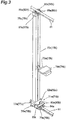
- the stacker crane 7A includes a traveling unit (first traveling unit) 71a, the mast 72a, a lifting platform (first lifting platform) 73a, the transferring device 74a, and an auxiliary traveling unit (first auxiliary traveling unit) 75a.
- the traveling unit 71a travels along the traveling path 5.
- the mast 72a is vertically provided on the traveling unit 71a.
- the lifting platform 73a is arranged so as to protrude from the mast 72a in the travel direction, and ascends and descends along the mast 72a.
- the transferring device 74a is provided to an upper portion of the lifting platform 73a.
- the transferring device 74a transfers an article H onto or from shelves 31, and also transfers the article H onto or from each loading-and-unloading port 4.
- the auxiliary traveling unit 75a travels along the auxiliary path 6.
- the traveling unit 71a includes a traveling drive wheel (first traveling drive wheel) 76a, a housing 77a, a traveling motor 78a, a pair of lifting-platform-side traveling guide wheels (first guide wheels) 79a and 79a, a supporting unit (first supporting unit) 80a, and a pair of mast-side traveling guide wheels 81a and 81a.
- the traveling drive wheel 76a rolls along the upper surface of the traveling rail 51.
- the traveling drive wheel 76a is arranged so as to overlap the mast 72a when viewed from the vertical direction.
- the housing 77a rotatably supports the traveling drive wheel 76a.
- the housing 77a is fixed to the lower end of the mast 72a.
- the traveling motor 78a is fixed to the housing 77a so as to protrude on the side of shelves 31 of the racks 3B.
- the traveling motor 78a is a driving source of the traveling drive wheel 76a.
- a lifting motor 82a that is a driving source of the lifting platform 73a is attached so as to protrude on the side of shelves 31 of the rack 3A.
- Each lifting-platform-side traveling guide wheel 79a rolls along a side surface of the traveling rail 51.
- Each lifting-platform-side traveling guide wheel 79a is arranged on the one side in the travel direction with respect to the traveling drive wheel 76a.
- the pair of the lifting-platform-side traveling guide wheels 79a and 79a hold the traveling rail 51 in the horizontal direction.
- the supporting unit 80a rotatably supports the pair of the lifting-platform-side traveling guide wheels 79a and 79a.
- the supporting unit 80a is arranged on the one side in the travel direction with respect to the traveling drive wheel 76a.
- the supporting unit 80a has a pair of portions arranged on both sides with respect to the traveling rail 51, and each of the portions supports each lifting-platform-side traveling guide wheel 79a.
- the lifting platform 73a can enter a space formed between the pair of the portions of the supporting unit 80a.
- the pair of the portions of the supporting unit 80a each include a protruded member protruded from the housing 77a and a supporting member protruded from the lower surface of the protruded member and rotatably supporting each lifting-platform-side traveling guide wheel 79a.
- Each mast-side traveling guide wheel 81a rolls along a side surface of the traveling rail 51.
- Each mast-side traveling guide wheel 81a is arranged so as to overlap the mast 72a when viewed from the vertical direction.
- the pair of the mast-side traveling guide wheels 81a and 81a hold the traveling rail 51 in the horizontal direction.
- Each mast-side traveling guide wheel 81a is rotatably attached to a lower portion of the housing 77a.
- a driven-wheel unit 83a is attached to the traveling unit 71a.
- the driven-wheel unit 83a is laid over between tips of the pair of the protruded members protruded from the housing 77a in the supporting unit 80a.
- the driven-wheel unit 83a includes a driven wheel 84a that can roll along the upper surface of the traveling rail 51.
- the driven-wheel unit 83a is removed from the traveling unit 71a after the stacker crane 7A is installed on the traveling rail 51 (see FIG. 1 ).
- the lifting platform 73a can enter the above-described space that the supporting unit 80a has.
- the auxiliary traveling unit 75a includes a pair of auxiliary drive wheels (first auxiliary drive wheels) 85a and 85a, a pair of auxiliary guide wheels 86a and 86a, and a housing 87a.
- Each auxiliary drive wheel 85a rolls along the auxiliary rail 61.
- the pair of the auxiliary drive wheels 85a and 85a hold the auxiliary rail 61 in the horizontal direction.
- Each auxiliary guide wheel 86a rolls along the auxiliary rail 61.
- the pair of the auxiliary guide wheels 86a and 86a hold the auxiliary rail 61 in the horizontal direction.
- the housing 87a is fixed to the upper end of the mast 72a.
- members that rotatably support the auxiliary drive wheels 85a and the auxiliary guide wheels 86a are attached to the housing 87a.
- an auxiliary motor (not depicted) that is a driving source of the auxiliary drive wheels 85a is attached.
- the traveling drive wheel 76a and the auxiliary drive wheels 85a and 85a are driven in a synchronized manner, whereby the attitude of the mast 72a is stabilized so that the mast 72a is kept substantially upright even when the above-described driven-wheel unit 83 a is removed.
- the stacker crane 7B has a configuration similar to that of the stacker crane 7A, and includes a traveling unit (second traveling unit) 71b, a mast 72b, a lifting platform (second lifting platform) 73b, a transferring device 74b, an auxiliary traveling unit 75b, and a lifting motor 82b.
- the traveling unit 71b has a configuration similar to that of the traveling unit 71a, and includes a traveling drive wheel (second traveling drive wheel) 76b, a housing 77b, a traveling motor 78b, a pair of lifting-platform-side traveling guide wheels 79b and 79b, a supporting unit 80b, and a pair of mast-side traveling guide wheels 81b and 81b.
- the auxiliary traveling unit 75b has a configuration similar to that of the auxiliary traveling unit 75a, and includes a pair of auxiliary drive wheels 85b and 85b, a pair of auxiliary guide wheels 86b and 86b, and a housing 87b.
- the lifting platform 73a protrudes on the one side (the stacker crane 7B side) in the travel direction with respect to the mast 72a.
- the lifting platform 73b protrudes on the other side (the stacker crane 7A side) in the travel direction with respect to the mast 72b.
- the transferring device 74a of the stacker crane 7A and the transferring device 74b of the stacker crane 7B can respectively face shelves 31 and 31 that are in the same position (row) in the horizontal direction by being disposed in different positions in the vertical direction.
- the stacker crane 7A and the stacker crane 7B travel along the traveling path 5, convey articles H between shelves 31 and the loading-and-unloading ports 4, and transfer the articles H onto or from the shelves 31 and the loading-and-unloading ports 4.
- the transferring device 74a of the stacker crane 7A and the transferring device 74b of the stacker crane 7B are disposed first in different positions in the vertical direction. Subsequently, the stacker crane 7A. and the stacker crane 7B are disposed so that the transferring device 74a of the stacker crane 7A and the transferring device 74b of the stacker crane 7B respectively face the shelves 31 and 31 that are in the same position in the horizontal direction.
- the articles H are transferred onto or from the shelves 31 that respectively face the stacker crane 7A and the stacker crane 7B.
- the article H may be transferred onto only either one of the stacker crane 7A and the stacker crane 7B.
- the stacker crane 7A If the stacker crane 7A has failed, for example, conveyance of articles H is continued by the stacker crane 7B. In this case, as depicted in FIG. 7 , the stacker crane 7A is disposed into the area A1 first. At this time, in the stacker crane 7A, restraint of the lifting platform 73a on the mast 72a is released and the lifting platform 73a is disposed in the lowermost position.
- shelves 31 that the transferring device 74b of the stacker crane 7B cannot face are three shelves 31 that are a shelf 31 at the lowermost level and a shelf 31 at a level next to the lowermost level in the row at the end on the other side and a shelf 31 at the lowermost level in the row next to the row at the end on the other side.
- the stacker crane 7B is caused to convey articles H.
- retraction of the stacker crane 7A may be performed by the driving force of the driving source or may be performed by man power of an operator.
- the transferring device 74b of the stacker crane 7B is disposed at the height of a desired shelf 31, and the stacker crane 7B is moved so that the transferring device 74b faces the desired shelf 31.
- the operator causes the lifting platform 73a of the stacker crane 7A to move to a position higher than the level next to the lowermost level, and causes the stacker crane 7B to move so that the transferring device 74b faces the desired shelf 31.
- a fence for example, that covers the retracted stacker crane 7A and the surroundings may be placed to secure the safety of the operator.
- stacker crane 7B is moved in such a manner that the stacker crane 7B does not interfere with the fence.
- conveyance of articles H can be continued by the stacker crane 7A.
- the lifting platform 73a of the stacker crane 7A is arranged on the one side in the travel direction with respect to the mast 72a, when an article H is transferred onto a shelf 31 at the end on the other side in the travel direction, the mast 72a juts out from the shelf 31 to the other side in the travel direction. Accordingly, an area for retracting the mast 72a needs to be provided in the automated warehouse 1.
- the traveling drive wheel 76a and the mast 72a are provided so as to overlap when viewed from the vertical direction.
- the traveling unit 71a includes the lifting-platform-side traveling guide wheels 79a and 79a arranged on the one side in the travel direction with respect to the traveling drive wheel 76a and configured to roll along the traveling path 5 and the supporting unit 80a arranged on the one side in the travel direction with respect to the traveling drive wheel 76a and supporting the lifting-platform-side traveling guide wheels 79a and 79a.
- the supporting unit 80a has a space that at least part of the lifting platform 73a can enter. Accordingly, the lifting-platform-side traveling guide wheels 79a and 79a and the supporting unit 80a are arranged on the same side as the lifting platform 73a with respect to the mast 72a.
- the installation area can be reduced. Furthermore, because at least part of the lifting platform 73a can enter the space that the supporting unit 80a has, the lifting platform 73a can be lowered down to a relatively low position. Thus, it is possible, for example, to increase the number of shelves 31 or to arrange a shelf 31 in a lower position. The same applies to the traveling unit 71b of the stacker crane 7B.
- the automated warehouse 1 further includes the auxiliary path 6 provided above the traveling path 5 so as to oppose the traveling path 5 and configured to assist the traveling of the stacker crane 7A.
- the stacker crane 7A further includes the auxiliary traveling unit 75a attached to the upper portion of the mast 72a and including the auxiliary drive wheel 85a configured to roll along the auxiliary path 6. Consequently, the traveling drive wheel 76a and the auxiliary drive wheels 85a and 85a are driven in a synchronized manner, whereby the attitude of the mast 72a can be stabilized.
- the automated warehouse 1 further includes the stacker crane 7B arranged on the one side in the travel direction with respect to the stacker crane 7A and configured to convey the articles H between shelves 31 and the loading-and-unloading ports 4.
- the stacker crane 7B includes the traveling unit 71b including the traveling drive wheel 76b configured to roll along the traveling path 5, the mast 72b that is vertically provided on the traveling unit 71b so as to overlap the traveling drive wheel 76b when viewed from the vertical direction, the lifting platform 73b arranged on the other side in the travel direction with respect to the mast 72b and configured to ascend and descend along the mast 72b, and the transferring device 74b provided to the lifting platform 73b.
- the lifting platform 73b of the stacker crane 7B is arranged on the other side in the travel direction with respect to the mast 72b, when an article H is transferred onto a shelf 31 at the end on the one side in the travel direction, the mast 72b juts out from the shelf 31 to the one side in the travel direction. Accordingly, an area for retracting the mast 72b needs to be provided in the automated warehouse 1.
- the traveling drive wheels 76b and the mast 72b are provided so as to overlap when viewed from the vertical direction.
- An operation method for the automated warehouse 1 of one example of the present embodiment includes: a first step of disposing the transferring device 74a of the stacker crane 7A and the transferring device 74b of the stacker crane 7B at different positions in the vertical direction; and a second step of, after the first step, disposing the stacker crane 7A and the stacker crane 7B so that the transferring device 74a of the stacker crane 7A and the transferring device 74b of the stacker crane 7B face shelves 31 at the same position in the horizontal direction.
- articles H can be transferred onto two shelves 31 at the same position in the horizontal direction, thus a plurality of articles H can be quickly conveyed.
- An operation method for the automated warehouse 1 of another example of the present embodiment includes, when the stacker crane 7A has failed, a first step of disposing the stacker crane 7A so that the transferring device 74a of the stacker crane 7A faces a shelf 31 at the end on the other side in the travel direction and a second step of causing the stacker crane 7B to convey articles H.
- the stacker crane 7A if the stacker crane 7A has failed, the stacker crane 7A is disposed so that the transferring device 74a faces the shelf 31 at the end on the other side in the travel direction.
- the stacker crane 7A may block a shelf 31, so that the stacker crane 7B may be unable to transfer an article H onto the shelf 31 blocked by the stacker crane 7A. Furthermore, in order to surely prevent the interference between the stacker crane 7A and the stacker crane 7B, the stacker crane 7B may be unable to transfer an article H onto a shelf 31 around the shelf 31 blocked by the stacker crane 7A.
Landscapes
- Engineering & Computer Science (AREA)
- Mechanical Engineering (AREA)
- Transportation (AREA)
- Structural Engineering (AREA)
- Civil Engineering (AREA)
- Life Sciences & Earth Sciences (AREA)
- Geology (AREA)
- Warehouses Or Storage Devices (AREA)
Claims (7)
- Un entrepôt automatisé (1), comprenant :une pluralité de rayons (31), chacun configuré pour accommoder un article (H);un port de chargement et de déchargement (4) où l'article (H) es chargé et déchargé ;un premier transstockeur (7A) configuré pour transporter l'article (H) entre les rayons (31) et le port de chargement et de déchargement (4) ; etune voie de déplacement (5) où le transstockeur (7A) se déplace, où le premier transstockeur (7A) comprendune première unité de déplacement (71a) comprenant une première roue d'entraînement de déplacement (76a) configurée pour rouler le long de la voie de déplacement (5),un premier mât (72a) prévu verticalement sur la première unité de déplacement (71a) pour chevaucher la première roue d'entraînement de déplacement (76a) vu d'un sens vertical,une première plateforme élévatrice (73a) arrangé sur un côté dans un sens de déplacement par rapport au premier mât (72a) et configuré pour monter et descendre le long du premier mât (72a),un premier dispositif de transfert (74a) prévu à la première plateforme élévatrice (73a),un premier moteur de déplacement (78a) configuré pour entraîner la première roue d'entraînement de déplacement (76a) ; etun premier moteur de déplacement (82a) configuré pour entraîner la première plateforme élévatrice (73a), oùun boîtier (77a) est attaché à l'extrémité inférieure du mât (72a) et supporté de manière rotative la roue d'entraînement de déplacement (76a) ;le premier moteur de déplacement (78a) est attaché au boîtier (77a) de sorte qu'il est en saillie sur le côté des rayons (31) des portants (3B) et le premier moteur élévateur (82a) est attaché au boîtier (77a) de sorte qu'il est en saillie sur le côté des rayons (31) des portants (3A), où le portant 3A et le portant 3B sont prévus de manière opposée,caractérisé en ce quel'unité de déplacement 71a comprend un pair de roues de guidage de déplacement du côté du mât 81a et 81a et en ce que- chaque roue de guidage de déplacement du côté du mât 81a roule le long d'une surface latérale du rail de déplacement 51, chaque roue de guidage de déplacement du côté du mât 81a est arrangée de sorte qu'elle chevauche le mât 72a, vue du sens vertical, le pair de roues de guidage de déplacement du côté du mât 81a et 81a supporte le rail de déplacement 51 dans le sens horizontal et chaque roue de guidage de déplacement du côté du mât 81a est attachée de manière rotative à une partie inférieure du boîtier 77a.
- L'entrepôt automatisé (1) selon la revendication 1,
caractérisé en ce que
la première unité de déplacement (71a) comprend une première roue de guidage (79a) arrangée sur un côté dans le sens de déplacement par rapport à la première roue d'entraînement de déplacement (76a) et configurée pour rouler le long de la voie de déplacement (5), et une première unité de support (80a) arrangée sur un côté dans le sens de déplacement par rapport à la première roue d'entraînement de déplacement (76a) et supportant la première roue de guidage (79a), et
la première unité de support (80a) comprend un espace où au moins une partie de la première plateforme élévatrice (73a) est autorisée d'entrer. - L'entrepôt automatisé (1) selon la revendication 2,
caractérisé en outre par une voie auxiliaire (6) prévue au-dessus de la voie de déplacement (5) pour être opposée à la voie de déplacement (5) et configurée pour assister le déplacement du premier transstockeur (7A), où le premier transstockeur (7A) comprend en outre une première unité de déplacement auxiliaire (75a) attachée à une partie supérieure du premier mât (72a) et comprenant une première roue d'entraînement auxiliaire (85a) configurée pour rouler le long de la voie auxiliaire (6). - L'entrepôt automatisé (1) selon une des revendications 1 à 3, caractérisé en outre par un deuxième transstockeur (7B) positionné sur un côté dans le sens de déplacement par rapport au premier transstockeur (7A) et configuré pour transporter l'article (H) entre les rayons (31) et le port de chargement et de déchargement (4), où
le deuxième transstockeur (7B) comprendune deuxième unité de déplacement (71b) comprenant une deuxième roue d'entraînement de déplacement (76b) configurée pour rouler le long de la voie de déplacement (5),un deuxième mât (72b) prévu verticalement sur la deuxième unité de déplacement (71b) pour chevaucher la deuxième roue d'entraînement de déplacement (76b) vu d'un sens vertical,une deuxième plateforme élévatrice (73b) arrangée sur l'autre côté dans le sens de déplacement par rapport au deuxième mât (72b) et configurée pour monter et descendre le long du deuxième mât (72b),un deuxième dispositif de transfert (74b) prévu à la deuxième plateforme élévatrice (73b),deuxième moteur de déplacement (78b) configuré pour entraîner la deuxième roue d'entraînement de déplacement (76b), etun deuxième moteur de déplacement (82b) configuré pour entraîner la deuxième plateforme élévatrice (73b),la deuxième unité de déplacement (71b), le deuxième moteur de déplacement (78b) et le deuxième moteur de déplacement (82b) sont arrangés, dans le sens de déplacement, sur l'autre côté par rapport à une extrémité du deuxième mât (72b) sur un côté,le deuxième moteur de déplacement (78b) est arrangé en saillie de la deuxième unité de déplacement (71b) vers un côté dans un sens croisant un sens d'extension du deuxième mât (72b) et le sens d'extension de la voie de déplacement (5), etle deuxième moteur de déplacement (82b) est arrangé en saillie de la deuxième unité de déplacement (71b) vers l'autre côté dans un sens croisant le sens d'extension du deuxième mât (72b) et le sens d'extension de la voie de déplacement (5). - Un procédé d'opération pour un entrepôt automatisé (1) selon la revendication 4, caractérisé par :une première étape qui consiste à déposer le premier dispositif de transfert (74a) et le deuxième dispositif de transfert (74b) dans des positions différentes dans le sens vertical ; etune deuxième étape qui consiste, après la première étape à déposer le premier transstockeur (7A) et le deuxième transstockeur (7B) de sorte que le premier dispositif de transfert (74a) et le deuxième dispositif de transfert (74b) font face à des rayons à une même position dans le sens horizontal.
- Un procédé d'opération pour un entrepôt automatisé (1) selon la revendication 4, caractérisé par :quand le premier transstockeur (7A) a échoué, une première étape qui consiste à déposer le premier transstockeur (7A) de sorte que le premier dispositif de transfert (74a) fait face au rayon à l'extrémité sur l'autre côté dans le sens de déplacement ;etune deuxième étape faisant que le deuxième transstockeur (7B) transporte l'article (H).
- Le procédé d'opération pour un entrepôt automatisé (1) selon la revendication 6, caractérisé en ce que pendant la deuxième étape, une restriction de la première plateforme élévatrice (73a) au premier mât (72a) est libérée au premier transstockeur (7A).
Applications Claiming Priority (2)
| Application Number | Priority Date | Filing Date | Title |
|---|---|---|---|
| JP2013136864 | 2013-06-28 | ||
| PCT/JP2014/063216 WO2014208217A1 (fr) | 2013-06-28 | 2014-05-19 | Entrepôt automatique et son procédé de fonctionnement |
Publications (3)
| Publication Number | Publication Date |
|---|---|
| EP3015401A1 EP3015401A1 (fr) | 2016-05-04 |
| EP3015401A4 EP3015401A4 (fr) | 2017-03-01 |
| EP3015401B1 true EP3015401B1 (fr) | 2018-07-04 |
Family
ID=52141569
Family Applications (1)
| Application Number | Title | Priority Date | Filing Date |
|---|---|---|---|
| EP14818090.4A Active EP3015401B1 (fr) | 2013-06-28 | 2014-05-19 | Entrepôt automatique et son procédé de fonctionnement |
Country Status (5)
| Country | Link |
|---|---|
| US (1) | US9764898B2 (fr) |
| EP (1) | EP3015401B1 (fr) |
| JP (1) | JP6137312B2 (fr) |
| TW (1) | TWI565640B (fr) |
| WO (1) | WO2014208217A1 (fr) |
Families Citing this family (3)
| Publication number | Priority date | Publication date | Assignee | Title |
|---|---|---|---|---|
| DE102016009000A1 (de) * | 2016-07-21 | 2018-01-25 | Liebherr-Verzahntechnik Gmbh | Regalbediengerät für ein Palettenspeichersystem |
| JP7367851B2 (ja) * | 2020-03-26 | 2023-10-24 | 村田機械株式会社 | 走行車システム |
| CN117799994A (zh) * | 2023-12-29 | 2024-04-02 | 江苏省特种设备安全监督检验研究院 | 用于钢板库巷道专用起重机 |
Family Cites Families (18)
| Publication number | Priority date | Publication date | Assignee | Title |
|---|---|---|---|---|
| US4417838A (en) * | 1980-12-23 | 1983-11-29 | Si Handling Systems, Inc. | Apparatus for loading articles into lanes on horizontal shelves |
| JPH083367Y2 (ja) | 1990-05-07 | 1996-01-31 | 石川島播磨重工業株式会社 | 立体自動倉庫 |
| CA2096703A1 (fr) * | 1993-04-02 | 1994-10-03 | Kurt M. Lloyd | Transtockeur automatique |
| JP2001019119A (ja) | 1999-07-01 | 2001-01-23 | Kito Corp | スタッカークレーン |
| AT500378B1 (de) * | 2001-06-13 | 2006-12-15 | Tgw Transportgeraete Gmbh | Regalbediengerät |
| JP3835377B2 (ja) | 2001-11-28 | 2006-10-18 | 村田機械株式会社 | スタッカークレーン |
| JP2004091136A (ja) | 2002-08-30 | 2004-03-25 | Murata Mach Ltd | 搬送装置 |
| JP2004277167A (ja) * | 2003-03-19 | 2004-10-07 | Hitachi Kiden Kogyo Ltd | 自動倉庫における複数台運用のスタッカクレーンのバックアップ方法 |
| JP4586990B2 (ja) * | 2005-05-27 | 2010-11-24 | 株式会社ダイフク | 物品収納設備 |
| EP1728738B1 (fr) * | 2005-05-31 | 2008-09-17 | Daifuku Co., Ltd. | Système de transport d'articles et procédé d'utilisation du sytème |
| TWI382949B (zh) * | 2005-06-15 | 2013-01-21 | Daifuku Kk | Item handling device |
| JP4689372B2 (ja) | 2005-07-04 | 2011-05-25 | 株式会社日立プラントテクノロジー | スタッカクレーンの走行駆動制御方法 |
| JP4666213B2 (ja) * | 2005-07-05 | 2011-04-06 | 株式会社ダイフク | 物品収納設備 |
| JP4228397B2 (ja) | 2006-08-29 | 2009-02-25 | 村田機械株式会社 | 自動倉庫 |
| US9221604B2 (en) * | 2008-09-05 | 2015-12-29 | Daifuku Co., Ltd. | Article storage facility and method of operation therefor |
| JP5136391B2 (ja) | 2008-12-22 | 2013-02-06 | 村田機械株式会社 | 自動倉庫 |
| ES2351333B1 (es) | 2010-09-06 | 2011-09-15 | Mecalux S.A. | Transelevador para el transporte de cargas. |
| JP2013006632A (ja) * | 2011-06-22 | 2013-01-10 | Renesas Electronics Corp | ストッカ |
-
2014
- 2014-05-19 EP EP14818090.4A patent/EP3015401B1/fr active Active
- 2014-05-19 WO PCT/JP2014/063216 patent/WO2014208217A1/fr not_active Ceased
- 2014-05-19 US US14/897,587 patent/US9764898B2/en active Active
- 2014-05-19 JP JP2015523919A patent/JP6137312B2/ja active Active
- 2014-06-27 TW TW103122243A patent/TWI565640B/zh active
Non-Patent Citations (1)
| Title |
|---|
| None * |
Also Published As
| Publication number | Publication date |
|---|---|
| US9764898B2 (en) | 2017-09-19 |
| JPWO2014208217A1 (ja) | 2017-02-23 |
| EP3015401A4 (fr) | 2017-03-01 |
| TW201515961A (zh) | 2015-05-01 |
| EP3015401A1 (fr) | 2016-05-04 |
| WO2014208217A1 (fr) | 2014-12-31 |
| TWI565640B (zh) | 2017-01-11 |
| JP6137312B2 (ja) | 2017-05-31 |
| US20160137414A1 (en) | 2016-05-19 |
Similar Documents
| Publication | Publication Date | Title |
|---|---|---|
| US11767204B2 (en) | Transport vehicle and transport facility | |
| JP6201977B2 (ja) | 自動倉庫及びその運転方法 | |
| EP2860136B1 (fr) | Système de transport et procédé de stockage temporaire d'articles dans un système de transport | |
| JP6314713B2 (ja) | 階間搬送設備 | |
| US10625938B2 (en) | Article transport facility | |
| EP4480861A2 (fr) | Véhicule de manipulation de conteneurs doté de première et seconde sections et ensemble de moteurs dans la seconde section pour entraîner au moins une roue de chacun des ensembles de roues | |
| CN104891081B (zh) | 物品支撑装置 | |
| EP3187437B1 (fr) | Entrepôt automatisé et procédé de commande d'entrepôt automatisé | |
| US8961095B2 (en) | Article storage system and maintenance method in article storage system | |
| CN109969667B (zh) | 自动仓库系统 | |
| EP2957527B1 (fr) | Installation de transport et entrepôt automatisé | |
| JP4844824B2 (ja) | 物品保管設備 | |
| WO2015060050A1 (fr) | Entrepôt automatisé et méthode d'exploitation de celui-ci | |
| JP2020152555A (ja) | 自動倉庫システム | |
| JP2021527013A (ja) | 遠隔操作車両をロックするためのロックデバイスを備えた容器アクセスステーションを備えた格納グリッド | |
| JP2021528332A (ja) | レールシステム上にある不具合のある車両を取り扱うための方法、および当該方法を利用する倉庫システム | |
| CN107055013A (zh) | 物品输送设备 | |
| US9764898B2 (en) | Automated warehouse and operation method for same | |
| JP4618513B2 (ja) | ピッキング式の物品収納設備 | |
| JP2001019113A (ja) | 自動倉庫 |
Legal Events
| Date | Code | Title | Description |
|---|---|---|---|
| PUAI | Public reference made under article 153(3) epc to a published international application that has entered the european phase |
Free format text: ORIGINAL CODE: 0009012 |
|
| 17P | Request for examination filed |
Effective date: 20151120 |
|
| AK | Designated contracting states |
Kind code of ref document: A1 Designated state(s): AL AT BE BG CH CY CZ DE DK EE ES FI FR GB GR HR HU IE IS IT LI LT LU LV MC MK MT NL NO PL PT RO RS SE SI SK SM TR |
|
| AX | Request for extension of the european patent |
Extension state: BA ME |
|
| DAX | Request for extension of the european patent (deleted) | ||
| A4 | Supplementary search report drawn up and despatched |
Effective date: 20170131 |
|
| RIC1 | Information provided on ipc code assigned before grant |
Ipc: B66F 9/07 20060101ALI20170125BHEP Ipc: B65G 1/04 20060101AFI20170125BHEP |
|
| STAA | Information on the status of an ep patent application or granted ep patent |
Free format text: STATUS: EXAMINATION IS IN PROGRESS |
|
| 17Q | First examination report despatched |
Effective date: 20171205 |
|
| GRAP | Despatch of communication of intention to grant a patent |
Free format text: ORIGINAL CODE: EPIDOSNIGR1 |
|
| STAA | Information on the status of an ep patent application or granted ep patent |
Free format text: STATUS: GRANT OF PATENT IS INTENDED |
|
| INTG | Intention to grant announced |
Effective date: 20180321 |
|
| GRAS | Grant fee paid |
Free format text: ORIGINAL CODE: EPIDOSNIGR3 |
|
| GRAA | (expected) grant |
Free format text: ORIGINAL CODE: 0009210 |
|
| STAA | Information on the status of an ep patent application or granted ep patent |
Free format text: STATUS: THE PATENT HAS BEEN GRANTED |
|
| AK | Designated contracting states |
Kind code of ref document: B1 Designated state(s): AL AT BE BG CH CY CZ DE DK EE ES FI FR GB GR HR HU IE IS IT LI LT LU LV MC MK MT NL NO PL PT RO RS SE SI SK SM TR |
|
| REG | Reference to a national code |
Ref country code: GB Ref legal event code: FG4D |
|
| REG | Reference to a national code |
Ref country code: CH Ref legal event code: EP |
|
| REG | Reference to a national code |
Ref country code: AT Ref legal event code: REF Ref document number: 1014262 Country of ref document: AT Kind code of ref document: T Effective date: 20180715 |
|
| REG | Reference to a national code |
Ref country code: IE Ref legal event code: FG4D |
|
| REG | Reference to a national code |
Ref country code: DE Ref legal event code: R096 Ref document number: 602014028021 Country of ref document: DE |
|
| REG | Reference to a national code |
Ref country code: NL Ref legal event code: MP Effective date: 20180704 |
|
| REG | Reference to a national code |
Ref country code: LT Ref legal event code: MG4D |
|
| REG | Reference to a national code |
Ref country code: AT Ref legal event code: MK05 Ref document number: 1014262 Country of ref document: AT Kind code of ref document: T Effective date: 20180704 |
|
| PG25 | Lapsed in a contracting state [announced via postgrant information from national office to epo] |
Ref country code: NL Free format text: LAPSE BECAUSE OF FAILURE TO SUBMIT A TRANSLATION OF THE DESCRIPTION OR TO PAY THE FEE WITHIN THE PRESCRIBED TIME-LIMIT Effective date: 20180704 |
|
| PG25 | Lapsed in a contracting state [announced via postgrant information from national office to epo] |
Ref country code: GR Free format text: LAPSE BECAUSE OF FAILURE TO SUBMIT A TRANSLATION OF THE DESCRIPTION OR TO PAY THE FEE WITHIN THE PRESCRIBED TIME-LIMIT Effective date: 20181005 Ref country code: NO Free format text: LAPSE BECAUSE OF FAILURE TO SUBMIT A TRANSLATION OF THE DESCRIPTION OR TO PAY THE FEE WITHIN THE PRESCRIBED TIME-LIMIT Effective date: 20181004 Ref country code: FI Free format text: LAPSE BECAUSE OF FAILURE TO SUBMIT A TRANSLATION OF THE DESCRIPTION OR TO PAY THE FEE WITHIN THE PRESCRIBED TIME-LIMIT Effective date: 20180704 Ref country code: SE Free format text: LAPSE BECAUSE OF FAILURE TO SUBMIT A TRANSLATION OF THE DESCRIPTION OR TO PAY THE FEE WITHIN THE PRESCRIBED TIME-LIMIT Effective date: 20180704 Ref country code: LT Free format text: LAPSE BECAUSE OF FAILURE TO SUBMIT A TRANSLATION OF THE DESCRIPTION OR TO PAY THE FEE WITHIN THE PRESCRIBED TIME-LIMIT Effective date: 20180704 Ref country code: RS Free format text: LAPSE BECAUSE OF FAILURE TO SUBMIT A TRANSLATION OF THE DESCRIPTION OR TO PAY THE FEE WITHIN THE PRESCRIBED TIME-LIMIT Effective date: 20180704 Ref country code: IS Free format text: LAPSE BECAUSE OF FAILURE TO SUBMIT A TRANSLATION OF THE DESCRIPTION OR TO PAY THE FEE WITHIN THE PRESCRIBED TIME-LIMIT Effective date: 20181104 Ref country code: PL Free format text: LAPSE BECAUSE OF FAILURE TO SUBMIT A TRANSLATION OF THE DESCRIPTION OR TO PAY THE FEE WITHIN THE PRESCRIBED TIME-LIMIT Effective date: 20180704 Ref country code: BG Free format text: LAPSE BECAUSE OF FAILURE TO SUBMIT A TRANSLATION OF THE DESCRIPTION OR TO PAY THE FEE WITHIN THE PRESCRIBED TIME-LIMIT Effective date: 20181004 Ref country code: AT Free format text: LAPSE BECAUSE OF FAILURE TO SUBMIT A TRANSLATION OF THE DESCRIPTION OR TO PAY THE FEE WITHIN THE PRESCRIBED TIME-LIMIT Effective date: 20180704 Ref country code: CZ Free format text: LAPSE BECAUSE OF FAILURE TO SUBMIT A TRANSLATION OF THE DESCRIPTION OR TO PAY THE FEE WITHIN THE PRESCRIBED TIME-LIMIT Effective date: 20180704 |
|
| PG25 | Lapsed in a contracting state [announced via postgrant information from national office to epo] |
Ref country code: AL Free format text: LAPSE BECAUSE OF FAILURE TO SUBMIT A TRANSLATION OF THE DESCRIPTION OR TO PAY THE FEE WITHIN THE PRESCRIBED TIME-LIMIT Effective date: 20180704 Ref country code: LV Free format text: LAPSE BECAUSE OF FAILURE TO SUBMIT A TRANSLATION OF THE DESCRIPTION OR TO PAY THE FEE WITHIN THE PRESCRIBED TIME-LIMIT Effective date: 20180704 Ref country code: ES Free format text: LAPSE BECAUSE OF FAILURE TO SUBMIT A TRANSLATION OF THE DESCRIPTION OR TO PAY THE FEE WITHIN THE PRESCRIBED TIME-LIMIT Effective date: 20180704 Ref country code: HR Free format text: LAPSE BECAUSE OF FAILURE TO SUBMIT A TRANSLATION OF THE DESCRIPTION OR TO PAY THE FEE WITHIN THE PRESCRIBED TIME-LIMIT Effective date: 20180704 |
|
| REG | Reference to a national code |
Ref country code: DE Ref legal event code: R097 Ref document number: 602014028021 Country of ref document: DE |
|
| PG25 | Lapsed in a contracting state [announced via postgrant information from national office to epo] |
Ref country code: EE Free format text: LAPSE BECAUSE OF FAILURE TO SUBMIT A TRANSLATION OF THE DESCRIPTION OR TO PAY THE FEE WITHIN THE PRESCRIBED TIME-LIMIT Effective date: 20180704 Ref country code: RO Free format text: LAPSE BECAUSE OF FAILURE TO SUBMIT A TRANSLATION OF THE DESCRIPTION OR TO PAY THE FEE WITHIN THE PRESCRIBED TIME-LIMIT Effective date: 20180704 Ref country code: IT Free format text: LAPSE BECAUSE OF FAILURE TO SUBMIT A TRANSLATION OF THE DESCRIPTION OR TO PAY THE FEE WITHIN THE PRESCRIBED TIME-LIMIT Effective date: 20180704 |
|
| PLBE | No opposition filed within time limit |
Free format text: ORIGINAL CODE: 0009261 |
|
| STAA | Information on the status of an ep patent application or granted ep patent |
Free format text: STATUS: NO OPPOSITION FILED WITHIN TIME LIMIT |
|
| PG25 | Lapsed in a contracting state [announced via postgrant information from national office to epo] |
Ref country code: SM Free format text: LAPSE BECAUSE OF FAILURE TO SUBMIT A TRANSLATION OF THE DESCRIPTION OR TO PAY THE FEE WITHIN THE PRESCRIBED TIME-LIMIT Effective date: 20180704 Ref country code: DK Free format text: LAPSE BECAUSE OF FAILURE TO SUBMIT A TRANSLATION OF THE DESCRIPTION OR TO PAY THE FEE WITHIN THE PRESCRIBED TIME-LIMIT Effective date: 20180704 Ref country code: SK Free format text: LAPSE BECAUSE OF FAILURE TO SUBMIT A TRANSLATION OF THE DESCRIPTION OR TO PAY THE FEE WITHIN THE PRESCRIBED TIME-LIMIT Effective date: 20180704 |
|
| 26N | No opposition filed |
Effective date: 20190405 |
|
| PG25 | Lapsed in a contracting state [announced via postgrant information from national office to epo] |
Ref country code: SI Free format text: LAPSE BECAUSE OF FAILURE TO SUBMIT A TRANSLATION OF THE DESCRIPTION OR TO PAY THE FEE WITHIN THE PRESCRIBED TIME-LIMIT Effective date: 20180704 |
|
| REG | Reference to a national code |
Ref country code: CH Ref legal event code: PL |
|
| GBPC | Gb: european patent ceased through non-payment of renewal fee |
Effective date: 20190519 |
|
| PG25 | Lapsed in a contracting state [announced via postgrant information from national office to epo] |
Ref country code: LI Free format text: LAPSE BECAUSE OF NON-PAYMENT OF DUE FEES Effective date: 20190531 Ref country code: CH Free format text: LAPSE BECAUSE OF NON-PAYMENT OF DUE FEES Effective date: 20190531 Ref country code: MC Free format text: LAPSE BECAUSE OF FAILURE TO SUBMIT A TRANSLATION OF THE DESCRIPTION OR TO PAY THE FEE WITHIN THE PRESCRIBED TIME-LIMIT Effective date: 20180704 |
|
| REG | Reference to a national code |
Ref country code: BE Ref legal event code: MM Effective date: 20190531 |
|
| PG25 | Lapsed in a contracting state [announced via postgrant information from national office to epo] |
Ref country code: LU Free format text: LAPSE BECAUSE OF NON-PAYMENT OF DUE FEES Effective date: 20190519 |
|
| PG25 | Lapsed in a contracting state [announced via postgrant information from national office to epo] |
Ref country code: TR Free format text: LAPSE BECAUSE OF FAILURE TO SUBMIT A TRANSLATION OF THE DESCRIPTION OR TO PAY THE FEE WITHIN THE PRESCRIBED TIME-LIMIT Effective date: 20180704 |
|
| PG25 | Lapsed in a contracting state [announced via postgrant information from national office to epo] |
Ref country code: GB Free format text: LAPSE BECAUSE OF NON-PAYMENT OF DUE FEES Effective date: 20190519 |
|
| PG25 | Lapsed in a contracting state [announced via postgrant information from national office to epo] |
Ref country code: BE Free format text: LAPSE BECAUSE OF NON-PAYMENT OF DUE FEES Effective date: 20190531 |
|
| PG25 | Lapsed in a contracting state [announced via postgrant information from national office to epo] |
Ref country code: FR Free format text: LAPSE BECAUSE OF NON-PAYMENT OF DUE FEES Effective date: 20190531 Ref country code: PT Free format text: LAPSE BECAUSE OF FAILURE TO SUBMIT A TRANSLATION OF THE DESCRIPTION OR TO PAY THE FEE WITHIN THE PRESCRIBED TIME-LIMIT Effective date: 20181104 |
|
| PG25 | Lapsed in a contracting state [announced via postgrant information from national office to epo] |
Ref country code: CY Free format text: LAPSE BECAUSE OF FAILURE TO SUBMIT A TRANSLATION OF THE DESCRIPTION OR TO PAY THE FEE WITHIN THE PRESCRIBED TIME-LIMIT Effective date: 20180704 |
|
| PG25 | Lapsed in a contracting state [announced via postgrant information from national office to epo] |
Ref country code: MT Free format text: LAPSE BECAUSE OF FAILURE TO SUBMIT A TRANSLATION OF THE DESCRIPTION OR TO PAY THE FEE WITHIN THE PRESCRIBED TIME-LIMIT Effective date: 20180704 Ref country code: HU Free format text: LAPSE BECAUSE OF FAILURE TO SUBMIT A TRANSLATION OF THE DESCRIPTION OR TO PAY THE FEE WITHIN THE PRESCRIBED TIME-LIMIT; INVALID AB INITIO Effective date: 20140519 |
|
| PG25 | Lapsed in a contracting state [announced via postgrant information from national office to epo] |
Ref country code: MK Free format text: LAPSE BECAUSE OF FAILURE TO SUBMIT A TRANSLATION OF THE DESCRIPTION OR TO PAY THE FEE WITHIN THE PRESCRIBED TIME-LIMIT Effective date: 20180704 |
|
| PGFP | Annual fee paid to national office [announced via postgrant information from national office to epo] |
Ref country code: DE Payment date: 20250423 Year of fee payment: 12 |
|
| PGFP | Annual fee paid to national office [announced via postgrant information from national office to epo] |
Ref country code: IE Payment date: 20250424 Year of fee payment: 12 |