EP3015629A1 - Système de poignée de porte de véhicule avec dispositif de prévention d'accident - Google Patents
Système de poignée de porte de véhicule avec dispositif de prévention d'accident Download PDFInfo
- Publication number
- EP3015629A1 EP3015629A1 EP15002507.0A EP15002507A EP3015629A1 EP 3015629 A1 EP3015629 A1 EP 3015629A1 EP 15002507 A EP15002507 A EP 15002507A EP 3015629 A1 EP3015629 A1 EP 3015629A1
- Authority
- EP
- European Patent Office
- Prior art keywords
- motor vehicle
- vehicle door
- handle assembly
- door handle
- lever
- Prior art date
- Legal status (The legal status is an assumption and is not a legal conclusion. Google has not performed a legal analysis and makes no representation as to the accuracy of the status listed.)
- Granted
Links
- 230000000694 effects Effects 0.000 claims abstract description 4
- 238000006073 displacement reaction Methods 0.000 claims description 10
- 230000002093 peripheral effect Effects 0.000 claims description 2
- 230000004888 barrier function Effects 0.000 description 11
- 230000000903 blocking effect Effects 0.000 description 8
- 230000003993 interaction Effects 0.000 description 4
- 230000008878 coupling Effects 0.000 description 2
- 238000010168 coupling process Methods 0.000 description 2
- 238000005859 coupling reaction Methods 0.000 description 2
- 230000000284 resting effect Effects 0.000 description 2
- 230000001960 triggered effect Effects 0.000 description 2
- 208000027418 Wounds and injury Diseases 0.000 description 1
- 230000001133 acceleration Effects 0.000 description 1
- 230000000712 assembly Effects 0.000 description 1
- 238000000429 assembly Methods 0.000 description 1
- 230000006378 damage Effects 0.000 description 1
- 238000011161 development Methods 0.000 description 1
- 230000018109 developmental process Effects 0.000 description 1
- 230000005484 gravity Effects 0.000 description 1
- 208000014674 injury Diseases 0.000 description 1
- 238000009434 installation Methods 0.000 description 1
Images


Classifications
-
- E—FIXED CONSTRUCTIONS
- E05—LOCKS; KEYS; WINDOW OR DOOR FITTINGS; SAFES
- E05B—LOCKS; ACCESSORIES THEREFOR; HANDCUFFS
- E05B85/00—Details of vehicle locks not provided for in groups E05B77/00 - E05B83/00
- E05B85/10—Handles
-
- E—FIXED CONSTRUCTIONS
- E05—LOCKS; KEYS; WINDOW OR DOOR FITTINGS; SAFES
- E05B—LOCKS; ACCESSORIES THEREFOR; HANDCUFFS
- E05B77/00—Vehicle locks characterised by special functions or purposes
- E05B77/02—Vehicle locks characterised by special functions or purposes for accident situations
- E05B77/04—Preventing unwanted lock actuation, e.g. unlatching, at the moment of collision
- E05B77/06—Preventing unwanted lock actuation, e.g. unlatching, at the moment of collision by means of inertial forces
Definitions
- the invention relates to a motor vehicle door handle assembly for actuating a motor vehicle door, with a reversing lever which is rotatably mounted about an axis and which acts on a motor vehicle door lock directly or indirectly on a motor vehicle door lock during rotation about the axis from a rest position to an actuation position to effect release of the lock and to allow an opening of the vehicle door.
- Such motor vehicle door handle assemblies for actuating a motor vehicle door are known.
- the problem with the known arrangements is that in case of an accident due to the forces acting on and the inertia of individual components can inadvertently get from the rest position to the operating position, so that it can happen in an accident that unlocks the door lock and open the door becomes. As a result, there is a significant risk of injury to the vehicle occupants.
- the object of the invention is therefore to develop a motor vehicle door handle assembly for actuating a motor vehicle door such that it has improved safety in the event of an accident of the motor vehicle.
- a motor vehicle door handle assembly according to claim 1.
- Advantageous developments of the invention are specified in the subclaims.
- the motor vehicle door handle assembly for actuating a motor vehicle door, with a reversing lever which is rotatably mounted about an axis and which acts on a rotation about the axis of a rest position in an operating position directly or indirectly on a motor vehicle door lock to effect a release of the lock and to allow an opening of the motor vehicle door, it is that the motor vehicle door handle assembly comprises an abutment which blocks the reversing lever after a plastic deformation of the motor vehicle door handle assembly.
- blockage of the reversing lever is meant that the arrangement of the abutment after a plastic deformation of the motor vehicle door handle assembly, for example, as a result of an accident of the motor vehicle, a rotation of the reversing lever is prevented about its axis from the rest position to the operating position.
- the abutment is formed by a body part and / or a disc, in particular side window of a motor vehicle and or a handle housing of the motor vehicle door handle assembly.
- the motor vehicle door handle assembly can thus be designed such that after installation in a motor vehicle door itself has an abutment example by the handle housing of the motor vehicle door handle assembly and or positioned so that in the case of plastic deformation of the motor vehicle door handle assembly, the abutment by a body part of the motor vehicle, in which the Vehicle door handle assembly is installed, engages and acts as a blocking element and blocks the lever.
- the abutment may be formed by a disk, in particular side window of the motor vehicle, in which the motor vehicle door handle assembly is installed.
- the motor vehicle door handle assembly is installed.
- motor vehicle doors on a particular retractable side window.
- this can be positioned so that the side window and or a body part of the motor vehicle door forms the abutment, which is effective after a plastic deformation of the motor vehicle door handle assembly as a blocking element and blocks the lever.
- the term of the motor vehicle door handle assembly is not limited to, for example, a motor vehicle door handle housing, but rather this term means the overall arrangement of the motor vehicle door handle in the motor vehicle door, which in particular serves as an abutment body part of the vehicle door and / or serving as an abutment disc, in particular a retractable disc of the motor vehicle, comprising.
- the abutment blocks after a plastic deformation of the reversing lever such that a rotation of the reversing lever about its axis of rotation in the operating position is impossible.
- the lever on its circumference at least one cam and / or at least one recess which cooperates with the abutment after a plastic deformation of the motor vehicle door handle assembly.
- the reversing lever may have on its circumference at least one cam, which is formed by at least one peripheral portion on the circumference of the reversing lever with an enlarged radius.
- the reversing lever may be configured such that, in the case of an undamaged motor vehicle door handle assembly, such a cam pivots past the abutment about the axis of rotation of the reversing lever during rotation of the reversing lever, thereby reducing the distance of the rotational axis of the reversing lever to the abutment due to plastic deformation and thereby a blockage of the reversing lever is effected in that the cam runs on the circumference of the reversing lever at a reduced distance from the axis of rotation to the abutment against the abutment and is blocked by this.
- the reversing lever may have a cam which is formed by at least one elevation on the reversing lever, which extends parallel to the axis of rotation of the reversing lever.
- a cam extending on the unlatching lever in a direction parallel to the axis of rotation of the reversing lever can then be engaged with a corresponding abutment after plastic deformation of the motor vehicle door handle assembly by running the cam against the abutment and thereby blocking rotation of the reversing lever.
- the motor vehicle door handle assembly comprises a handle which is displaceable from a rest position to an open position, wherein a arranged on the back of the handle handle hook is kinematically coupled to the lever and causes displacement of the handle in the open position, a rotation of the reversing lever in its operating position.
- the handle when the motor vehicle door lock is unlocked, the handle is gripped by the user and is moved from a rest position into an open position for opening the motor vehicle door.
- the handle has on its back on a handle hook, which is kinematically coupled directly or indirectly with the lever.
- a rotation of the reversing lever about its axis of rotation from the rest position in the Actuating position of the reversing lever causes, so that when the vehicle door lock unlocked an opening of the vehicle door is possible.
- the reversing lever and / or a handle which is coupled to the reversing lever, spring-loaded in the direction of the rest position.
- the reversing lever is coupled via a push rod and / or a pull rod and / or a cable to the motor vehicle door lock, whereby the opening of the motor vehicle door lock is effected in an unlocked motor vehicle door lock during rotation of the reversing lever in its operating position.
- the reversing lever has at least one locking element which engages with an accidental lock on occurrence of an external pulse as a result of a side impact and blocks a displacement of the reversing lever and the handle from the rest position to its actuated position.
- the movable masses, any spring constants when a spring load and the ease of the joints of the motor vehicle door handle assembly and in particular the crash barrier are chosen so that when a pulse occurs, for example as a result of an accident, the crash barrier is so smooth and has a corresponding inertia that First, the crash barrier with the locking element on the bellcrank comes into engagement and thereby blocks the bellcrank, before the handle and the lever could be displaced out of the rest position due to the pulse. This accident protection reliable opening of the door due to an impact or other events is prevented.
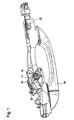
- FIGS. 1 and 2 a perspective view of a portion of a motor vehicle door handle assembly for actuating a motor vehicle door.
- Fig. 1 shows the arrangement in the rest position during Fig. 2 the arrangement in the operating position shows, in which the lever 10 from the rest position according to Fig. 1 in the operating position according to Fig. 2 is displaced by rotation about its axis of rotation 11.
- the handle 20, which is kinematically coupled to the reversing lever 10 also in Fig. 1 in the rest position while the handle 20 in Fig. 2 is displaced by a rotation about its axis of rotation 23 in the actuation position to the opening of the motor vehicle door, not shown.
- the lever 10 is kinematically coupled by the engaging in corresponding receptacles on the lever 10 axle stub 22 with the end of the mandrel 21 on the handle 20. This means that by a displacement of the handle 20 from the rest position according to Fig. 1 in the Actuation position according to Fig. 2 on the kinematic coupling at the same time the lever 10 about its axis of rotation 11 around from the rest position according to Fig. 1 in the operating position according to Fig. 2 is relocated.
- the reversing lever 10 is connected via a Bowden cable, not shown, with a door lock, not shown, of a motor vehicle door. In the displacement of the reversing lever 10 by rotation about its axis of rotation 11 in the operating position according to Fig. 2 If the door lock is not completed, the lock is released and the opening of the motor vehicle door, not shown, is made possible.
- the handle 20 is in turn rotatably mounted about its axis of rotation 23 in a handle housing, not shown.
- FIGS. 1 and 2 Clearly recognizable in the FIGS. 1 and 2 is a cam 12 on the lever 10, whose interaction with an abutment on the basis of Figures 3 and 4 is explained.
- Fig. 3 shows a side view of the area of the reversing lever in an enlarged view in the rest position of the reversing lever 10th
- FIG. 3 plotted a portion of the abutment 30.
- the motor vehicle door handle assembly is not plastically deformed as a result of an accident, so that the cam 12 of the reversing lever 10 at a rotation of the reversing lever 10 about its axis of rotation 11 in the operating position as indicated by the arrow 31 can swing past the abutment 30.
- Fig. 4 The mode of action of the abutment 30 becomes clear in Fig. 4 in which an enlarged section of the region of the reversing lever 10 is shown after a plastic deformation of the motor vehicle door handle assembly as a result of a Unfah mechanisms.
- the abutment 30 serves as a blocking element with respect to the cam 12 of the reversing lever 10, so that rotation of the reversing lever 10 in the operating position about the rotation axis 11 due to the interaction of abutment 30 and cam 12 of the reversing lever 10 is no longer possible.
- the cam 12 on the reversing lever 10 no longer swing past the abutment 30, so that the lever 10 thereby in accordance with its rest position Fig. 1 is blocked.
- a retractable side window of the motor vehicle in the motor vehicle door, in which the motor vehicle door handle assembly is installed serves as an abutment 30.
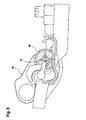
- Fig. 5 shows a perspective view of the rear view of the vehicle door handle assembly with the handle 20 and the lever 10th
- a second crash barrier 40 which is formed by a circular disc 40 having two recesses, whose operation is explained with reference to the other figures.
- a locking lug 13 can be seen, which cooperates with the circular disk 40 and whose operation will be explained below.
- Fig. 6 shows an enlarged section of a perspective view with the arranged on the lever 10 locking lug 13 and the recess having a circular disk 40, which serves as a further crash barrier.
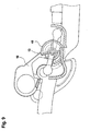
- FIGS. 7 . 8th and 9 the arrangement is shown in an enlarged side view. It can be seen how the lever 10 with the locking lug 13 disposed thereon from the rest position according to Fig. 7 via an intermediate position according to Fig. 8 in the operating position according to Fig. 9 is displaced while the locking lug 13 of the reversing lever 10 slides into a corresponding recess on serving as an accidental disc 40 inside.
- the recess on the circular disc 40 is positioned accordingly that the latch 13 can slide freely in a shift from the rest position according to Fig. 7 about the in Fig. 8 shown intermediate position in the operating position of the reversing lever 10 according to Fig. 9 to open the door lock.
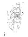
- FIG. 10 and 11 the operation of serving as a further crash barrier disc 40 which is coupled to respective inertial masses 41, 42.
- the circular disk 40 has two diametrically opposite recesses and thus a symmetrical design, so that the arrangement can be used on both sides of a motor vehicle.
- inertial masses 41, 42 There are two inertial masses 41, 42 arranged, which are arranged on levers.
- the levers of the inertial masses 41, 42 are rotatably mounted on the same axis about which the circular disk 40 is rotatable.
- the inertial masses 41, 42 supporting levers are freely rotatable relative to the circular disk 40, so that they are deflected by any external impulses, as they occur in an accident, ie, are rotatable about the common axis 45 with the circular disk 40.
- the disk 40 is disc-shaped as explained and has two diametrically opposite recesses.
- the recess is arranged radially outwardly extending in the circular disk 40 and positioned so that the locking lug 13 can pivot into the recess in the circular disk 40 in the rest position of the circular disk 40 and thus a movement of the reversing lever 10 for opening the vehicle door is possible.
- the arrangement of two diametrically opposite recesses on the circumference of the circular disk 40 serves the usability of the crash barrier on both sides of the vehicle.
- a rotation of the circular disk 40 from the rest position according to FIGS. 5 to 9 out causes a blocking of the locking lug 13 and thus blocking the reversing lever 10th
- the crash barrier further includes a first inertial mass 41 and a second inertial mass 42.
- These inertial masses 41, 42 are each arranged on a lever arm, which are mounted rotatably on the axis of rotation 45 and are rotatable relative to the circular disk 40.
- the lever-shaped inertia masses 41, 42 each have a center of gravity, which is arranged offset to the axis of rotation 45, so that the inertial masses 41, 42 under action of an acceleration force (for example, as a result of a side impact in the direction of the vehicle interior) from its basic position, in the FIGS. 5 to 9 is shown, can move out in a deflection direction.
- an acceleration force for example, as a result of a side impact in the direction of the vehicle interior
- the lever-shaped inertial masses 41, 42 cooperate with the circular disk 40.
- the circular disc 40 on each of the two side surfaces in each case a projection 43, 44 which is parallel to the Rotation axis 45 of the circular disc 40 extends from the side surface of the circular disc 40 and thus serves as a driver.
- the projections 43, 44 are arranged diametrically on the circular disk 40 and are located on different side surfaces of the circular disk 40, as shown in particular in FIG FIG. 10 is recognizable.
- the circular disk 40 is disposed between the two inertial masses 41, 42 on the rotation axis 45, wherein the inertial masses 41, 42 are rotatable relative to the circular disk 40 about the rotation axis 45 around.
- the first inertial mass 41 is assigned and acts in the case of a deflection of the first inertial mass 41 from its rest position with this together.
- the second inertial mass 42 is assigned and acts in the case of a deflection of the second inertial mass 42 from its rest position with this together.
- Fig. 10 shows the operation of the circular disk 40 at a pulse from the outside shown by the arrow 50.
- the inertia of the inertial mass 41 the circular disk 40 is rotated counterclockwise. Accordingly, the recess on the circular disc 40 is also displaced and the latching lug 13 on the reversing lever is blocked, so that the reversing lever 10 does not pivot into its actuated position can.
- the rotation of the circular disk 40 takes place as a result of the interaction of the first inertial mass 41 with the first protrusion 43 serving as a driver on the front side of the circular disk 40 as shown FIG. 10 ,
- Fig. 11 shows the opposite case with a pulse from the inside according to the arrow 51.
- the second inertial mass 42 is effective and rotates the disk 40 such that in turn the locking lug 13 is blocked by the circular disk 40 and a rotation of the reversing lever 10 in the operating position is prevented.
- the rotation of the circular disk 40 takes place in this case according to FIG. 11 due to the interaction of the second inertial mass 42 with the serving as a driver second projection 44 on the back of the circular disk 40 as shown FIG. 11 ,
- the circular disc 40 also acts as an accidental lock, so that the reversing lever 10 is blocked even in the event that no plastic deformation occurs and the reversing lever 10 would not yet blocked by a plastic deformation by the abutment 30 as explained above.
- the circular disk 40 which is effective as a further crash barrier becomes correspondingly effective both in the case of an impulse from the outside, as in FIG Fig. 10 is shown, as well as a pulse from the inside, as shown in Fig. 11 is shown and the lever 10 is blocked in each case in its rest position, so that accidental opening of the vehicle door in the event of an accident is reliably prevented.
Landscapes
- Lock And Its Accessories (AREA)
Applications Claiming Priority (1)
| Application Number | Priority Date | Filing Date | Title |
|---|---|---|---|
| DE102014015949.3A DE102014015949A1 (de) | 2014-10-30 | 2014-10-30 | Kraftfahrzeugtürgriffanordnung mit Unfallsicherung |
Publications (2)
| Publication Number | Publication Date |
|---|---|
| EP3015629A1 true EP3015629A1 (fr) | 2016-05-04 |
| EP3015629B1 EP3015629B1 (fr) | 2020-06-03 |
Family
ID=54011487
Family Applications (1)
| Application Number | Title | Priority Date | Filing Date |
|---|---|---|---|
| EP15002507.0A Active EP3015629B1 (fr) | 2014-10-30 | 2015-08-24 | Système de poignée de porte de véhicule avec dispositif de prévention d'accident |
Country Status (3)
| Country | Link |
|---|---|
| EP (1) | EP3015629B1 (fr) |
| CN (1) | CN105569468B (fr) |
| DE (1) | DE102014015949A1 (fr) |
Cited By (3)
| Publication number | Priority date | Publication date | Assignee | Title |
|---|---|---|---|---|
| DE102016223505A1 (de) | 2016-11-28 | 2018-05-30 | Volkswagen Aktiengesellschaft | Türgriffeinrichtung für eine Tür eines Kraftfahrzeugs, Tür, Kraftfahrzeug |
| US10689887B2 (en) | 2018-01-10 | 2020-06-23 | Toyota Motor Engineering & Manufacturing North America, Inc. | Door latch assemblies for vehicles including bell crank blocking structures |
| US20210246692A1 (en) * | 2018-07-05 | 2021-08-12 | Kiekert Ag | Lock for a motor vehicle |
Families Citing this family (7)
| Publication number | Priority date | Publication date | Assignee | Title |
|---|---|---|---|---|
| CN106320856A (zh) * | 2016-08-30 | 2017-01-11 | 丰业迪睦斯(芜湖)汽车部件有限公司 | 汽车外门把手支架的换向机构 |
| CN107217928A (zh) * | 2017-07-05 | 2017-09-29 | 广东顶固集创家居股份有限公司 | 一种锁及其拉手组件、门、汽车 |
| DE102017008519A1 (de) * | 2017-09-09 | 2019-03-14 | Daimler Ag | Zentralverriegelungseinrichtung für ein Türschloss mit Unfall-Erkennungseinrichtung |
| FR3090719B1 (fr) * | 2018-12-20 | 2021-01-22 | Mgi Coutier Espana | Commande d’ouverture à remontage mécanique. |
| DE102019007824B4 (de) | 2019-11-12 | 2023-06-07 | Mercedes-Benz Group AG | Kraftfahrzeugtür |
| CN112112484B (zh) * | 2020-10-27 | 2025-08-26 | 广州保仕盾智能科技有限公司 | 一种全自动智能门锁的把手锁定装置 |
| EP4592480A1 (fr) * | 2024-01-25 | 2025-07-30 | Minebea AccessSolutions Italia S.p.A. | Ensemble poignée de porte de véhicule |
Citations (5)
| Publication number | Priority date | Publication date | Assignee | Title |
|---|---|---|---|---|
| DE10260900A1 (de) * | 2002-12-20 | 2004-07-01 | Huf Hülsbeck & Fürst Gmbh & Co. Kg | Türaußengriff |
| DE102008062213A1 (de) * | 2008-12-13 | 2010-06-17 | Dr.Ing.H.C.F.Porsche Aktiengesellschaft | Türgriffeinrichtung |
| DE102008062214A1 (de) * | 2008-12-13 | 2010-07-08 | Dr.Ing.H.C.F.Porsche Aktiengesellschaft | Türgriffeinrichtung |
| FR2946077A1 (fr) * | 2009-05-26 | 2010-12-03 | Peugeot Citroen Automobiles Sa | Dispositif de commande de l'ouverture d'un ouvrant d'un vehicule automobile comportant un moyen pour empecher cette ouverture, en cas de choc lateral, ouvrant ainsi equipe et vehicule comportant un tel ouvrant. |
| WO2012065938A1 (fr) * | 2010-11-16 | 2012-05-24 | Valeo S.P.A. | Poignee de vehicule automobile ayant une masse inertielle de blocage actionnee par un contrepoids |
Family Cites Families (1)
| Publication number | Priority date | Publication date | Assignee | Title |
|---|---|---|---|---|
| US8727399B2 (en) * | 2009-10-27 | 2014-05-20 | Honda Motor Co., Ltd. | Device for prevention of door opening during roll-over |
-
2014
- 2014-10-30 DE DE102014015949.3A patent/DE102014015949A1/de not_active Withdrawn
-
2015
- 2015-08-24 EP EP15002507.0A patent/EP3015629B1/fr active Active
- 2015-10-30 CN CN201510726109.8A patent/CN105569468B/zh not_active Expired - Fee Related
Patent Citations (5)
| Publication number | Priority date | Publication date | Assignee | Title |
|---|---|---|---|---|
| DE10260900A1 (de) * | 2002-12-20 | 2004-07-01 | Huf Hülsbeck & Fürst Gmbh & Co. Kg | Türaußengriff |
| DE102008062213A1 (de) * | 2008-12-13 | 2010-06-17 | Dr.Ing.H.C.F.Porsche Aktiengesellschaft | Türgriffeinrichtung |
| DE102008062214A1 (de) * | 2008-12-13 | 2010-07-08 | Dr.Ing.H.C.F.Porsche Aktiengesellschaft | Türgriffeinrichtung |
| FR2946077A1 (fr) * | 2009-05-26 | 2010-12-03 | Peugeot Citroen Automobiles Sa | Dispositif de commande de l'ouverture d'un ouvrant d'un vehicule automobile comportant un moyen pour empecher cette ouverture, en cas de choc lateral, ouvrant ainsi equipe et vehicule comportant un tel ouvrant. |
| WO2012065938A1 (fr) * | 2010-11-16 | 2012-05-24 | Valeo S.P.A. | Poignee de vehicule automobile ayant une masse inertielle de blocage actionnee par un contrepoids |
Cited By (4)
| Publication number | Priority date | Publication date | Assignee | Title |
|---|---|---|---|---|
| DE102016223505A1 (de) | 2016-11-28 | 2018-05-30 | Volkswagen Aktiengesellschaft | Türgriffeinrichtung für eine Tür eines Kraftfahrzeugs, Tür, Kraftfahrzeug |
| US10689887B2 (en) | 2018-01-10 | 2020-06-23 | Toyota Motor Engineering & Manufacturing North America, Inc. | Door latch assemblies for vehicles including bell crank blocking structures |
| US20210246692A1 (en) * | 2018-07-05 | 2021-08-12 | Kiekert Ag | Lock for a motor vehicle |
| US12173533B2 (en) * | 2018-07-05 | 2024-12-24 | Kiekert Ag | Lock for a motor vehicle |
Also Published As
| Publication number | Publication date |
|---|---|
| DE102014015949A1 (de) | 2016-05-04 |
| EP3015629B1 (fr) | 2020-06-03 |
| CN105569468A (zh) | 2016-05-11 |
| CN105569468B (zh) | 2020-06-19 |
Similar Documents
| Publication | Publication Date | Title |
|---|---|---|
| EP3015629B1 (fr) | Système de poignée de porte de véhicule avec dispositif de prévention d'accident | |
| EP2999836B1 (fr) | Serrure pour un véhicule à moteur | |
| EP2326781B1 (fr) | Unité de serrure comportant des cliquets d'arrêt à plusieurs parties et un cliquet de blocage précontraint par ressort | |
| EP3049598B1 (fr) | Poignée de porte de véhicule automobile | |
| EP2295681B1 (fr) | Mécanisme d'ouverture et/ou de fermeture sur des portes, des clapets ou analogues, notamment sur des véhicules | |
| EP2133495B1 (fr) | Serrure de véhicule automobile | |
| EP2813653B1 (fr) | Agencement de poignée de porte pour un véhicule | |
| DE10319366B4 (de) | Fronthaubenscharnier mit integriertem Fußgängerschutz-Aktuator | |
| EP3394371B1 (fr) | Dispositif de sécurité pour un véhicule à moteur comprenant un pêne pivotant et une position de préverrouillage et une position de verrouillage principal | |
| EP2818614B1 (fr) | Agencement de poignée de porte pour un véhicule | |
| WO2012055387A2 (fr) | Serrure de porte de véhicule automobile | |
| DE102011101284B4 (de) | Verriegelungsvorrichtung | |
| WO2015149744A1 (fr) | Dispositif d'actionnement pour serrure de véhicule à moteur | |
| EP2828456B1 (fr) | Verrouillage de portière de véhicule automobile | |
| DE102016212511A1 (de) | Fahrzeugtürgriffvorrichtung | |
| DE102017216920A1 (de) | Türgriffeinrichtung für eine Tür eines Kraftfahrzeugs, Tür, Kraftfahrzeug | |
| DE102015109946A1 (de) | Kraftfahrzeugschloss | |
| EP2080857A2 (fr) | Agencement de poignée extérieure de porte pour véhicules | |
| DE102022130601A1 (de) | Griffanordnung eines Kraftfahrzeugs | |
| EP3990726B1 (fr) | Serrure de porte, en particulier serrure de portière de véhicule automobile | |
| DE102018128420A1 (de) | Kraftfahrzeugschloss | |
| EP3117057B1 (fr) | Système de fermeture de portière de véhicule automobile | |
| EP2743432B1 (fr) | Poignée pour un dispositif de fermeture d'un véhicule automobile, comprenant une butée de masse inertielle prenant en compte des accélérations actives provenant de différentes directions | |
| EP3870785B1 (fr) | Serrure de véhicule automobile, en particulier serrure de porte de véhicule automobile | |
| DE202010015399U1 (de) | Kraftfahrzeugtürverschluss |
Legal Events
| Date | Code | Title | Description |
|---|---|---|---|
| PUAI | Public reference made under article 153(3) epc to a published international application that has entered the european phase |
Free format text: ORIGINAL CODE: 0009012 |
|
| AK | Designated contracting states |
Kind code of ref document: A1 Designated state(s): AL AT BE BG CH CY CZ DE DK EE ES FI FR GB GR HR HU IE IS IT LI LT LU LV MC MK MT NL NO PL PT RO RS SE SI SK SM TR |
|
| AX | Request for extension of the european patent |
Extension state: BA ME |
|
| 17P | Request for examination filed |
Effective date: 20161010 |
|
| RBV | Designated contracting states (corrected) |
Designated state(s): AL AT BE BG CH CY CZ DE DK EE ES FI FR GB GR HR HU IE IS IT LI LT LU LV MC MK MT NL NO PL PT RO RS SE SI SK SM TR |
|
| STAA | Information on the status of an ep patent application or granted ep patent |
Free format text: STATUS: EXAMINATION IS IN PROGRESS |
|
| 17Q | First examination report despatched |
Effective date: 20190611 |
|
| GRAP | Despatch of communication of intention to grant a patent |
Free format text: ORIGINAL CODE: EPIDOSNIGR1 |
|
| STAA | Information on the status of an ep patent application or granted ep patent |
Free format text: STATUS: GRANT OF PATENT IS INTENDED |
|
| INTG | Intention to grant announced |
Effective date: 20200110 |
|
| GRAS | Grant fee paid |
Free format text: ORIGINAL CODE: EPIDOSNIGR3 |
|
| GRAA | (expected) grant |
Free format text: ORIGINAL CODE: 0009210 |
|
| STAA | Information on the status of an ep patent application or granted ep patent |
Free format text: STATUS: THE PATENT HAS BEEN GRANTED |
|
| AK | Designated contracting states |
Kind code of ref document: B1 Designated state(s): AL AT BE BG CH CY CZ DE DK EE ES FI FR GB GR HR HU IE IS IT LI LT LU LV MC MK MT NL NO PL PT RO RS SE SI SK SM TR |
|
| REG | Reference to a national code |
Ref country code: GB Ref legal event code: FG4D Free format text: NOT ENGLISH |
|
| REG | Reference to a national code |
Ref country code: AT Ref legal event code: REF Ref document number: 1277176 Country of ref document: AT Kind code of ref document: T Effective date: 20200615 Ref country code: CH Ref legal event code: EP |
|
| REG | Reference to a national code |
Ref country code: DE Ref legal event code: R096 Ref document number: 502015012688 Country of ref document: DE |
|
| REG | Reference to a national code |
Ref country code: LT Ref legal event code: MG4D |
|
| PG25 | Lapsed in a contracting state [announced via postgrant information from national office to epo] |
Ref country code: GR Free format text: LAPSE BECAUSE OF FAILURE TO SUBMIT A TRANSLATION OF THE DESCRIPTION OR TO PAY THE FEE WITHIN THE PRESCRIBED TIME-LIMIT Effective date: 20200904 Ref country code: LT Free format text: LAPSE BECAUSE OF FAILURE TO SUBMIT A TRANSLATION OF THE DESCRIPTION OR TO PAY THE FEE WITHIN THE PRESCRIBED TIME-LIMIT Effective date: 20200603 Ref country code: FI Free format text: LAPSE BECAUSE OF FAILURE TO SUBMIT A TRANSLATION OF THE DESCRIPTION OR TO PAY THE FEE WITHIN THE PRESCRIBED TIME-LIMIT Effective date: 20200603 Ref country code: NO Free format text: LAPSE BECAUSE OF FAILURE TO SUBMIT A TRANSLATION OF THE DESCRIPTION OR TO PAY THE FEE WITHIN THE PRESCRIBED TIME-LIMIT Effective date: 20200903 Ref country code: SE Free format text: LAPSE BECAUSE OF FAILURE TO SUBMIT A TRANSLATION OF THE DESCRIPTION OR TO PAY THE FEE WITHIN THE PRESCRIBED TIME-LIMIT Effective date: 20200603 |
|
| PGFP | Annual fee paid to national office [announced via postgrant information from national office to epo] |
Ref country code: FR Payment date: 20200820 Year of fee payment: 6 |
|
| REG | Reference to a national code |
Ref country code: NL Ref legal event code: MP Effective date: 20200603 |
|
| PG25 | Lapsed in a contracting state [announced via postgrant information from national office to epo] |
Ref country code: HR Free format text: LAPSE BECAUSE OF FAILURE TO SUBMIT A TRANSLATION OF THE DESCRIPTION OR TO PAY THE FEE WITHIN THE PRESCRIBED TIME-LIMIT Effective date: 20200603 Ref country code: LV Free format text: LAPSE BECAUSE OF FAILURE TO SUBMIT A TRANSLATION OF THE DESCRIPTION OR TO PAY THE FEE WITHIN THE PRESCRIBED TIME-LIMIT Effective date: 20200603 Ref country code: RS Free format text: LAPSE BECAUSE OF FAILURE TO SUBMIT A TRANSLATION OF THE DESCRIPTION OR TO PAY THE FEE WITHIN THE PRESCRIBED TIME-LIMIT Effective date: 20200603 Ref country code: BG Free format text: LAPSE BECAUSE OF FAILURE TO SUBMIT A TRANSLATION OF THE DESCRIPTION OR TO PAY THE FEE WITHIN THE PRESCRIBED TIME-LIMIT Effective date: 20200903 |
|
| PG25 | Lapsed in a contracting state [announced via postgrant information from national office to epo] |
Ref country code: NL Free format text: LAPSE BECAUSE OF FAILURE TO SUBMIT A TRANSLATION OF THE DESCRIPTION OR TO PAY THE FEE WITHIN THE PRESCRIBED TIME-LIMIT Effective date: 20200603 Ref country code: AL Free format text: LAPSE BECAUSE OF FAILURE TO SUBMIT A TRANSLATION OF THE DESCRIPTION OR TO PAY THE FEE WITHIN THE PRESCRIBED TIME-LIMIT Effective date: 20200603 |
|
| PG25 | Lapsed in a contracting state [announced via postgrant information from national office to epo] |
Ref country code: ES Free format text: LAPSE BECAUSE OF FAILURE TO SUBMIT A TRANSLATION OF THE DESCRIPTION OR TO PAY THE FEE WITHIN THE PRESCRIBED TIME-LIMIT Effective date: 20200603 Ref country code: CZ Free format text: LAPSE BECAUSE OF FAILURE TO SUBMIT A TRANSLATION OF THE DESCRIPTION OR TO PAY THE FEE WITHIN THE PRESCRIBED TIME-LIMIT Effective date: 20200603 Ref country code: RO Free format text: LAPSE BECAUSE OF FAILURE TO SUBMIT A TRANSLATION OF THE DESCRIPTION OR TO PAY THE FEE WITHIN THE PRESCRIBED TIME-LIMIT Effective date: 20200603 Ref country code: PT Free format text: LAPSE BECAUSE OF FAILURE TO SUBMIT A TRANSLATION OF THE DESCRIPTION OR TO PAY THE FEE WITHIN THE PRESCRIBED TIME-LIMIT Effective date: 20201006 Ref country code: IT Free format text: LAPSE BECAUSE OF FAILURE TO SUBMIT A TRANSLATION OF THE DESCRIPTION OR TO PAY THE FEE WITHIN THE PRESCRIBED TIME-LIMIT Effective date: 20200603 Ref country code: SM Free format text: LAPSE BECAUSE OF FAILURE TO SUBMIT A TRANSLATION OF THE DESCRIPTION OR TO PAY THE FEE WITHIN THE PRESCRIBED TIME-LIMIT Effective date: 20200603 Ref country code: EE Free format text: LAPSE BECAUSE OF FAILURE TO SUBMIT A TRANSLATION OF THE DESCRIPTION OR TO PAY THE FEE WITHIN THE PRESCRIBED TIME-LIMIT Effective date: 20200603 |
|
| PG25 | Lapsed in a contracting state [announced via postgrant information from national office to epo] |
Ref country code: IS Free format text: LAPSE BECAUSE OF FAILURE TO SUBMIT A TRANSLATION OF THE DESCRIPTION OR TO PAY THE FEE WITHIN THE PRESCRIBED TIME-LIMIT Effective date: 20201003 Ref country code: SK Free format text: LAPSE BECAUSE OF FAILURE TO SUBMIT A TRANSLATION OF THE DESCRIPTION OR TO PAY THE FEE WITHIN THE PRESCRIBED TIME-LIMIT Effective date: 20200603 Ref country code: PL Free format text: LAPSE BECAUSE OF FAILURE TO SUBMIT A TRANSLATION OF THE DESCRIPTION OR TO PAY THE FEE WITHIN THE PRESCRIBED TIME-LIMIT Effective date: 20200603 |
|
| REG | Reference to a national code |
Ref country code: DE Ref legal event code: R097 Ref document number: 502015012688 Country of ref document: DE |
|
| PG25 | Lapsed in a contracting state [announced via postgrant information from national office to epo] |
Ref country code: MC Free format text: LAPSE BECAUSE OF FAILURE TO SUBMIT A TRANSLATION OF THE DESCRIPTION OR TO PAY THE FEE WITHIN THE PRESCRIBED TIME-LIMIT Effective date: 20200603 |
|
| REG | Reference to a national code |
Ref country code: CH Ref legal event code: PL |
|
| PLBE | No opposition filed within time limit |
Free format text: ORIGINAL CODE: 0009261 |
|
| STAA | Information on the status of an ep patent application or granted ep patent |
Free format text: STATUS: NO OPPOSITION FILED WITHIN TIME LIMIT |
|
| PG25 | Lapsed in a contracting state [announced via postgrant information from national office to epo] |
Ref country code: LI Free format text: LAPSE BECAUSE OF NON-PAYMENT OF DUE FEES Effective date: 20200831 Ref country code: LU Free format text: LAPSE BECAUSE OF NON-PAYMENT OF DUE FEES Effective date: 20200824 Ref country code: DK Free format text: LAPSE BECAUSE OF FAILURE TO SUBMIT A TRANSLATION OF THE DESCRIPTION OR TO PAY THE FEE WITHIN THE PRESCRIBED TIME-LIMIT Effective date: 20200603 Ref country code: CH Free format text: LAPSE BECAUSE OF NON-PAYMENT OF DUE FEES Effective date: 20200831 |
|
| 26N | No opposition filed |
Effective date: 20210304 |
|
| GBPC | Gb: european patent ceased through non-payment of renewal fee |
Effective date: 20200903 |
|
| REG | Reference to a national code |
Ref country code: BE Ref legal event code: MM Effective date: 20200831 |
|
| PG25 | Lapsed in a contracting state [announced via postgrant information from national office to epo] |
Ref country code: SI Free format text: LAPSE BECAUSE OF FAILURE TO SUBMIT A TRANSLATION OF THE DESCRIPTION OR TO PAY THE FEE WITHIN THE PRESCRIBED TIME-LIMIT Effective date: 20200603 |
|
| PG25 | Lapsed in a contracting state [announced via postgrant information from national office to epo] |
Ref country code: GB Free format text: LAPSE BECAUSE OF NON-PAYMENT OF DUE FEES Effective date: 20200903 Ref country code: IE Free format text: LAPSE BECAUSE OF NON-PAYMENT OF DUE FEES Effective date: 20200824 Ref country code: BE Free format text: LAPSE BECAUSE OF NON-PAYMENT OF DUE FEES Effective date: 20200831 |
|
| REG | Reference to a national code |
Ref country code: AT Ref legal event code: MM01 Ref document number: 1277176 Country of ref document: AT Kind code of ref document: T Effective date: 20200824 |
|
| PG25 | Lapsed in a contracting state [announced via postgrant information from national office to epo] |
Ref country code: AT Free format text: LAPSE BECAUSE OF NON-PAYMENT OF DUE FEES Effective date: 20200824 |
|
| PGFP | Annual fee paid to national office [announced via postgrant information from national office to epo] |
Ref country code: DE Payment date: 20210831 Year of fee payment: 7 |
|
| PG25 | Lapsed in a contracting state [announced via postgrant information from national office to epo] |
Ref country code: TR Free format text: LAPSE BECAUSE OF FAILURE TO SUBMIT A TRANSLATION OF THE DESCRIPTION OR TO PAY THE FEE WITHIN THE PRESCRIBED TIME-LIMIT Effective date: 20200603 Ref country code: MT Free format text: LAPSE BECAUSE OF FAILURE TO SUBMIT A TRANSLATION OF THE DESCRIPTION OR TO PAY THE FEE WITHIN THE PRESCRIBED TIME-LIMIT Effective date: 20200603 Ref country code: CY Free format text: LAPSE BECAUSE OF FAILURE TO SUBMIT A TRANSLATION OF THE DESCRIPTION OR TO PAY THE FEE WITHIN THE PRESCRIBED TIME-LIMIT Effective date: 20200603 |
|
| PG25 | Lapsed in a contracting state [announced via postgrant information from national office to epo] |
Ref country code: MK Free format text: LAPSE BECAUSE OF FAILURE TO SUBMIT A TRANSLATION OF THE DESCRIPTION OR TO PAY THE FEE WITHIN THE PRESCRIBED TIME-LIMIT Effective date: 20200603 |
|
| PG25 | Lapsed in a contracting state [announced via postgrant information from national office to epo] |
Ref country code: FR Free format text: LAPSE BECAUSE OF NON-PAYMENT OF DUE FEES Effective date: 20210831 |
|
| REG | Reference to a national code |
Ref country code: DE Ref legal event code: R119 Ref document number: 502015012688 Country of ref document: DE |
|
| PG25 | Lapsed in a contracting state [announced via postgrant information from national office to epo] |
Ref country code: DE Free format text: LAPSE BECAUSE OF NON-PAYMENT OF DUE FEES Effective date: 20230301 |