EP3015687A1 - Verfahren zur regelung eines dual-fuel-motors - Google Patents
Verfahren zur regelung eines dual-fuel-motors Download PDFInfo
- Publication number
- EP3015687A1 EP3015687A1 EP15002840.5A EP15002840A EP3015687A1 EP 3015687 A1 EP3015687 A1 EP 3015687A1 EP 15002840 A EP15002840 A EP 15002840A EP 3015687 A1 EP3015687 A1 EP 3015687A1
- Authority
- EP
- European Patent Office
- Prior art keywords
- fuel
- combustion chamber
- amount
- knock
- intensity
- Prior art date
- Legal status (The legal status is an assumption and is not a legal conclusion. Google has not performed a legal analysis and makes no representation as to the accuracy of the status listed.)
- Granted
Links
Images


Classifications
-
- F—MECHANICAL ENGINEERING; LIGHTING; HEATING; WEAPONS; BLASTING
- F02—COMBUSTION ENGINES; HOT-GAS OR COMBUSTION-PRODUCT ENGINE PLANTS
- F02D—CONTROLLING COMBUSTION ENGINES
- F02D41/00—Electrical control of supply of combustible mixture or its constituents
- F02D41/0025—Controlling engines characterised by use of non-liquid fuels, pluralities of fuels, or non-fuel substances added to the combustible mixtures
- F02D41/0027—Controlling engines characterised by use of non-liquid fuels, pluralities of fuels, or non-fuel substances added to the combustible mixtures the fuel being gaseous
-
- F—MECHANICAL ENGINEERING; LIGHTING; HEATING; WEAPONS; BLASTING
- F02—COMBUSTION ENGINES; HOT-GAS OR COMBUSTION-PRODUCT ENGINE PLANTS
- F02D—CONTROLLING COMBUSTION ENGINES
- F02D19/00—Controlling engines characterised by their use of non-liquid fuels, pluralities of fuels, or non-fuel substances added to the combustible mixtures
- F02D19/06—Controlling engines characterised by their use of non-liquid fuels, pluralities of fuels, or non-fuel substances added to the combustible mixtures peculiar to engines working with pluralities of fuels, e.g. alternatively with light and heavy fuel oil, other than engines indifferent to the fuel consumed
- F02D19/08—Controlling engines characterised by their use of non-liquid fuels, pluralities of fuels, or non-fuel substances added to the combustible mixtures peculiar to engines working with pluralities of fuels, e.g. alternatively with light and heavy fuel oil, other than engines indifferent to the fuel consumed simultaneously using pluralities of fuels
- F02D19/10—Controlling engines characterised by their use of non-liquid fuels, pluralities of fuels, or non-fuel substances added to the combustible mixtures peculiar to engines working with pluralities of fuels, e.g. alternatively with light and heavy fuel oil, other than engines indifferent to the fuel consumed simultaneously using pluralities of fuels peculiar to compression-ignition engines in which the main fuel is gaseous
-
- F—MECHANICAL ENGINEERING; LIGHTING; HEATING; WEAPONS; BLASTING
- F02—COMBUSTION ENGINES; HOT-GAS OR COMBUSTION-PRODUCT ENGINE PLANTS
- F02D—CONTROLLING COMBUSTION ENGINES
- F02D19/00—Controlling engines characterised by their use of non-liquid fuels, pluralities of fuels, or non-fuel substances added to the combustible mixtures
- F02D19/06—Controlling engines characterised by their use of non-liquid fuels, pluralities of fuels, or non-fuel substances added to the combustible mixtures peculiar to engines working with pluralities of fuels, e.g. alternatively with light and heavy fuel oil, other than engines indifferent to the fuel consumed
- F02D19/0602—Control of components of the fuel supply system
- F02D19/0607—Control of components of the fuel supply system to adjust the fuel mass or volume flow
- F02D19/061—Control of components of the fuel supply system to adjust the fuel mass or volume flow by controlling fuel injectors
-
- F—MECHANICAL ENGINEERING; LIGHTING; HEATING; WEAPONS; BLASTING
- F02—COMBUSTION ENGINES; HOT-GAS OR COMBUSTION-PRODUCT ENGINE PLANTS
- F02D—CONTROLLING COMBUSTION ENGINES
- F02D19/00—Controlling engines characterised by their use of non-liquid fuels, pluralities of fuels, or non-fuel substances added to the combustible mixtures
- F02D19/06—Controlling engines characterised by their use of non-liquid fuels, pluralities of fuels, or non-fuel substances added to the combustible mixtures peculiar to engines working with pluralities of fuels, e.g. alternatively with light and heavy fuel oil, other than engines indifferent to the fuel consumed
- F02D19/0639—Controlling engines characterised by their use of non-liquid fuels, pluralities of fuels, or non-fuel substances added to the combustible mixtures peculiar to engines working with pluralities of fuels, e.g. alternatively with light and heavy fuel oil, other than engines indifferent to the fuel consumed characterised by the type of fuels
- F02D19/0642—Controlling engines characterised by their use of non-liquid fuels, pluralities of fuels, or non-fuel substances added to the combustible mixtures peculiar to engines working with pluralities of fuels, e.g. alternatively with light and heavy fuel oil, other than engines indifferent to the fuel consumed characterised by the type of fuels at least one fuel being gaseous, the other fuels being gaseous or liquid at standard conditions
- F02D19/0647—Controlling engines characterised by their use of non-liquid fuels, pluralities of fuels, or non-fuel substances added to the combustible mixtures peculiar to engines working with pluralities of fuels, e.g. alternatively with light and heavy fuel oil, other than engines indifferent to the fuel consumed characterised by the type of fuels at least one fuel being gaseous, the other fuels being gaseous or liquid at standard conditions the gaseous fuel being liquefied petroleum gas [LPG], liquefied natural gas [LNG], compressed natural gas [CNG] or dimethyl ether [DME]
-
- F—MECHANICAL ENGINEERING; LIGHTING; HEATING; WEAPONS; BLASTING
- F02—COMBUSTION ENGINES; HOT-GAS OR COMBUSTION-PRODUCT ENGINE PLANTS
- F02D—CONTROLLING COMBUSTION ENGINES
- F02D19/00—Controlling engines characterised by their use of non-liquid fuels, pluralities of fuels, or non-fuel substances added to the combustible mixtures
- F02D19/06—Controlling engines characterised by their use of non-liquid fuels, pluralities of fuels, or non-fuel substances added to the combustible mixtures peculiar to engines working with pluralities of fuels, e.g. alternatively with light and heavy fuel oil, other than engines indifferent to the fuel consumed
- F02D19/08—Controlling engines characterised by their use of non-liquid fuels, pluralities of fuels, or non-fuel substances added to the combustible mixtures peculiar to engines working with pluralities of fuels, e.g. alternatively with light and heavy fuel oil, other than engines indifferent to the fuel consumed simultaneously using pluralities of fuels
- F02D19/081—Adjusting the fuel composition or mixing ratio; Transitioning from one fuel to the other
-
- F—MECHANICAL ENGINEERING; LIGHTING; HEATING; WEAPONS; BLASTING
- F02—COMBUSTION ENGINES; HOT-GAS OR COMBUSTION-PRODUCT ENGINE PLANTS
- F02D—CONTROLLING COMBUSTION ENGINES
- F02D19/00—Controlling engines characterised by their use of non-liquid fuels, pluralities of fuels, or non-fuel substances added to the combustible mixtures
- F02D19/06—Controlling engines characterised by their use of non-liquid fuels, pluralities of fuels, or non-fuel substances added to the combustible mixtures peculiar to engines working with pluralities of fuels, e.g. alternatively with light and heavy fuel oil, other than engines indifferent to the fuel consumed
- F02D19/08—Controlling engines characterised by their use of non-liquid fuels, pluralities of fuels, or non-fuel substances added to the combustible mixtures peculiar to engines working with pluralities of fuels, e.g. alternatively with light and heavy fuel oil, other than engines indifferent to the fuel consumed simultaneously using pluralities of fuels
- F02D19/10—Controlling engines characterised by their use of non-liquid fuels, pluralities of fuels, or non-fuel substances added to the combustible mixtures peculiar to engines working with pluralities of fuels, e.g. alternatively with light and heavy fuel oil, other than engines indifferent to the fuel consumed simultaneously using pluralities of fuels peculiar to compression-ignition engines in which the main fuel is gaseous
- F02D19/105—Controlling engines characterised by their use of non-liquid fuels, pluralities of fuels, or non-fuel substances added to the combustible mixtures peculiar to engines working with pluralities of fuels, e.g. alternatively with light and heavy fuel oil, other than engines indifferent to the fuel consumed simultaneously using pluralities of fuels peculiar to compression-ignition engines in which the main fuel is gaseous operating in a special mode, e.g. in a liquid fuel only mode for starting
-
- F—MECHANICAL ENGINEERING; LIGHTING; HEATING; WEAPONS; BLASTING
- F02—COMBUSTION ENGINES; HOT-GAS OR COMBUSTION-PRODUCT ENGINE PLANTS
- F02D—CONTROLLING COMBUSTION ENGINES
- F02D35/00—Controlling engines, dependent on conditions exterior or interior to engines, not otherwise provided for
- F02D35/02—Controlling engines, dependent on conditions exterior or interior to engines, not otherwise provided for on interior conditions
- F02D35/027—Controlling engines, dependent on conditions exterior or interior to engines, not otherwise provided for on interior conditions using knock sensors
-
- F—MECHANICAL ENGINEERING; LIGHTING; HEATING; WEAPONS; BLASTING
- F02—COMBUSTION ENGINES; HOT-GAS OR COMBUSTION-PRODUCT ENGINE PLANTS
- F02D—CONTROLLING COMBUSTION ENGINES
- F02D41/00—Electrical control of supply of combustible mixture or its constituents
- F02D41/0025—Controlling engines characterised by use of non-liquid fuels, pluralities of fuels, or non-fuel substances added to the combustible mixtures
-
- F—MECHANICAL ENGINEERING; LIGHTING; HEATING; WEAPONS; BLASTING
- F02—COMBUSTION ENGINES; HOT-GAS OR COMBUSTION-PRODUCT ENGINE PLANTS
- F02D—CONTROLLING COMBUSTION ENGINES
- F02D41/00—Electrical control of supply of combustible mixture or its constituents
- F02D41/30—Controlling fuel injection
- F02D41/3011—Controlling fuel injection according to or using specific or several modes of combustion
- F02D41/3017—Controlling fuel injection according to or using specific or several modes of combustion characterised by the mode(s) being used
- F02D41/3035—Controlling fuel injection according to or using specific or several modes of combustion characterised by the mode(s) being used a mode being the premixed charge compression-ignition mode
- F02D41/3041—Controlling fuel injection according to or using specific or several modes of combustion characterised by the mode(s) being used a mode being the premixed charge compression-ignition mode with means for triggering compression ignition, e.g. spark plug
- F02D41/3047—Controlling fuel injection according to or using specific or several modes of combustion characterised by the mode(s) being used a mode being the premixed charge compression-ignition mode with means for triggering compression ignition, e.g. spark plug said means being a secondary injection of fuel
-
- F—MECHANICAL ENGINEERING; LIGHTING; HEATING; WEAPONS; BLASTING
- F02—COMBUSTION ENGINES; HOT-GAS OR COMBUSTION-PRODUCT ENGINE PLANTS
- F02D—CONTROLLING COMBUSTION ENGINES
- F02D41/00—Electrical control of supply of combustible mixture or its constituents
- F02D41/0002—Controlling intake air
- F02D41/0007—Controlling intake air for control of turbo-charged or super-charged engines
-
- Y—GENERAL TAGGING OF NEW TECHNOLOGICAL DEVELOPMENTS; GENERAL TAGGING OF CROSS-SECTIONAL TECHNOLOGIES SPANNING OVER SEVERAL SECTIONS OF THE IPC; TECHNICAL SUBJECTS COVERED BY FORMER USPC CROSS-REFERENCE ART COLLECTIONS [XRACs] AND DIGESTS
- Y02—TECHNOLOGIES OR APPLICATIONS FOR MITIGATION OR ADAPTATION AGAINST CLIMATE CHANGE
- Y02T—CLIMATE CHANGE MITIGATION TECHNOLOGIES RELATED TO TRANSPORTATION
- Y02T10/00—Road transport of goods or passengers
- Y02T10/10—Internal combustion engine [ICE] based vehicles
- Y02T10/30—Use of alternative fuels, e.g. biofuels
Definitions
- the present invention relates to a method for controlling a dual-fuel engine, having the features of the preamble of claim 1 and a dual-fuel engine having the features of claim 10.
- Generic engines can be operated in pure diesel or heavy oil operation or in a so-called dual-fuel mode in which the predominant fuel is a gas and diesel or heavy oil is used only for ignition assistance.
- Such an internal combustion engine goes out of the US 8,671,911 B2 out.
- This publication provides the arrangement of a knock sensor by which the presence of a knock is detectable.
- a control unit can regulate the amounts of gaseous and liquid fuel to the combustion chambers of the internal combustion engine.
- a disadvantage of the prior art is that an ignition delay (“retard ignition”) is mandatory in response to the detection of knocking.
- This control strategy does not take into account that tapping can be for a variety of reasons and therefore is not always effective. It may therefore be necessary in some cases to take additional measures, as in the case of US 8,671,911 B2 is described (reduction of the amount of gas introduced).
- the object of the invention is the provision of a method for controlling a generic dual-fuel engine and the provision of a dual-fuel engine, which responds or more differentiated to the presence of knocking.
- the amount of first gaseous fuel supplied to the combustion chamber of the engine is not reduced immediately in the presence of knocking.
- the invention provides (based on a duty cycle of the dual-fuel engine) to increase the amount of first, gaseous fuel initially (until possible exceeding a higher threshold or the decay of knocking). It should be noted for the present disclosure that the gaseous state of aggregation of the first fuel must be present only at the time of combustion.
- the power contribution caused by the second fuel is correspondingly reduced, for example by a reduction in the amount of second fuel introduced and / or a delay in the timing of the introduction of the second fuel and / or Changing the injection characteristic of the second fuel is made.
- the amount of second fuel introduced is a pilot amount which is less than 5% of the total amount of energy introduced by fuel in the amount of energy introduced.
- the combustion in the at least one combustion chamber is moderated to keep the extent of knocking within an acceptable range. This allows operation of the engine at an operating point with the highest possible proportion of the first fuel, which is desirable for economic considerations and on the other emission-related advantageous.
- the intensity of the knock signal is determined by the frequency of the knock events and the severity of the knock events. For example, high-intensity knocking can be caused by frequent, weak knocking and infrequent, strong knocking.
- Injection characteristic is the shape of the profile of the mass flow of the injected fuel as a function of time.
- the area under the profile which corresponds to the total amount of injected fuel, does not necessarily have to change as a result of such a change in shape.
- the change in the injection characteristic may be such that the majority of the injected amount of second fuel occurs later.
- later is meant at a later time within the injection event.
- the person skilled in variations of the injection characteristic are familiar.
- the first fuel before introduction into the at least one combustion chamber is admixed with an air.
- a mixture of the first fuel and the air in the at least one combustion chamber before the actual combustion take place.
- the amount of first fuel supplied to the at least one combustion chamber may be increased to lower the temperature of the mixture of air and first fuel even without changing the pressure (boost pressure) .
- boost pressure the pressure
- an increase of the supplied amount of first fuel also by increasing the pressure (boost pressure) take place.
- the first fuel is admixed with an air (in front of the at least one combustion chamber) and the ratio of first fuel and air is increased in order to increase the amount of first fuel.
- This measure is possible both in port-injection engines (through a port-injection valve) and in mixed-charge engines (through a gas-metering device).
- the first gaseous fuel may be, for example, a methane-dominated fuel (for example natural gas), a biogas, a propane gas (LPG), a gasified liquefied natural gas (LNG), a gasified LPG or a gasified gasoline.
- the second fuel may be, for example, diesel, vegetable oil or heavy fuel oil.
- the multiple injection concept known per se for the introduction of diesel or heavy fuel oil may be used to control the injection characteristics.
- the second fuel is injected in this case at several intervals.
- this concept is used when there is a knocking signal indicative of knocking at an intensity that is between the first and second intensities.
- the total power of the combustion chamber during a duty cycle of the dual-fuel engine must be kept constant. Therefore, the power contribution caused by the second fuel over a duty cycle of the dual-fuel engine is correspondingly reduced.
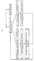
- Fig. 1 shows the method in a first embodiment as a schematic flow diagram.
- knock occurs, a distinction is made between two branches. Although in the left branch the knock intensity is above the first threshold (ie, a knock signal is detected that indicates knock over the first intensity), but below the second threshold (ie, a knock signal is detected indicating tapping below the second intensity ). Then the amount of first fuel supplied to the combustion chamber is increased.
- the increased power input caused by increasing the amount of first fuel is compensated by a reduction in the power contribution of the second fuel.
- Examples of possible interventions for reducing the second fuel's contribution to performance are (individually or in any combination) the reduction in the amount of second fuel, the delay of the injection time of the second fuel, the change in the injection rate of the second fuel, multiple injection of the second fuel.
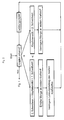
- Fig. 2 An alternative embodiment is in Fig. 2 shown.
- the power control circuit is connected in series with the knock control circuit. This means that after working through the Fig. 1 described in the case of tapping the loop leads directly to the power controller. So here is the knock detection as part of the power controller to see. It only becomes active when knocking is detected. If there is no knock signal, the same control as in Fig. 1 at the point "Start".
- Fig. 1 and 2 the power control loop according to the prior art is formed.
- the power specification can take place, for example, in the form of a torque or a rotational speed.
- this can be done, for example, in the form of a speed request.
- Fig. 3 shows a diagram of the combustion air ratio lambda as a function of the proportion of the second fuel, expressed in percent of the power contribution. At the origin of the graph, the proportion of the second fuel is "zero". Signed are two sets of curves for different boost pressures. The lower set of curves, which consists of a solid and a dotted line, represents the case for a lower boost pressure, the upper set of curves for a higher boost pressure.
- the solid line represents the global lambda, i. the air ratio based on both fuels dar. shown dotted is the lambda relative to the first fuel.
- a larger lambda means lean mixture.
- the global lambda i. H. the global mixture composition remains constant with respect to its stoichiometric ratio to the combustion air. This is achieved by increasing the lambda of the first fuel (shown in dotted lines) as the proportion of second fuel increases.
- An increase in the lambda means a higher dilution, so an emaciation of the mixture.
- the diagram illustrates in an illustrative way how it is possible to keep the global combustion air ratio constant even as the proportion of second fuel changes.
- Fig. 4 schematically shows a combustion chamber of a dual-fuel engine according to the invention 1.
- the combustion chamber has an inlet and an outlet side.
- the combustion chamber 4 Via the inlet duct 2 is the combustion chamber 4 a quantity of fuel Q 1.fuel within a unit time, ie, a "Q-point" of a first fuel (Fuel 1), Q 1.fuel supplied.
- Q 1.fuel a quantity of fuel
- a mass flow (mass per time) of air is introduced into the combustion chamber, in the figure, this is referred to as ⁇ air .
- the supply of first fuel and air into the intake tract 2 is made clear by black arrows. Also shown is an injection unit 5, via which the second fuel (2nd fuel) can be introduced into the combustion chamber.
- the amount of second fuel per unit time is referred to in the figure as Q ⁇ 2.fuel .
- the supply of second fuel is also visualized by a black arrow.
- a knock sensor 6 by means of which a knocking signal representative of the at least one combustion chamber 4 can be fed to a control or regulating device 7 of the dual-fuel engine 1.
Landscapes
- Engineering & Computer Science (AREA)
- Chemical & Material Sciences (AREA)
- Combustion & Propulsion (AREA)
- Mechanical Engineering (AREA)
- General Engineering & Computer Science (AREA)
- Oil, Petroleum & Natural Gas (AREA)
- Output Control And Ontrol Of Special Type Engine (AREA)
- Combined Controls Of Internal Combustion Engines (AREA)
- Electrical Control Of Air Or Fuel Supplied To Internal-Combustion Engine (AREA)
Abstract
Description
- Die vorliegende Erfindung betrifft ein Verfahren zur Regelung eines Dual-Fuel-Motors, mit den Merkmalen des Oberbegriffs des Anspruchs 1 und einen Dual-Fuel-Motor mit den Merkmalen des Anspruchs 10.
- Gattungsgemäße Motoren können in reinem Diesel- oder Schwerölbetrieb oder in einem sogenannten Dual-Fuel-Modus betrieben werden, in welchem die vorherrschende Kraftstoffart ein Gas ist und Diesel bzw. Schweröl lediglich zur Zündunterstützung verwendet wird. Eine derartige Brennkraftmaschine geht aus der
US 8,671,911 B2 hervor. - Diese Veröffentlichung sieht die Anordnung eines Klopfsensors vor, durch welchen das Vorliegen eines Klopfens detektierbar ist. In Abhängigkeit des Detektionssignals kann eine Regeleinheit die Mengen von gasförmigem und flüssigem Kraftstoff zu den Brennräumen der Brennkraftmaschine regeln.
- Nachteilig am Stand der Technik ist, dass als Reaktion auf die Detektion eines Klopfens zwingend eine Zündverzögerung ("retard ignition") vorgesehen ist. Diese Regelstrategie berücksichtigt nicht, dass Klopfen aus unterschiedlichen Gründen vorliegen kann und ist daher nicht immer zielführend. Es kann daher in manchen Fällen erforderlich sein, zusätzliche Maßnahmen zu ergreifen, wie dies auch in der
US 8,671,911 B2 beschrieben ist (Reduktion der eingebrachten Gasmenge). - Aufgabe der Erfindung ist die Bereitstellung eines Verfahrens zur Regelung eines gattungsgemäßen Dual-Fuel-Motors und die Bereitstellung eines Dual-Fuel-Motors, welches bzw. welcher differenzierter auf das Vorliegen von Klopfen reagiert.
- Diese Aufgabe wird durch ein Verfahren mit den Merkmalen des Anspruchs 1 und einen Dual-Fuel-Motor mit den Merkmalen des Anspruchs 10 gelöst.
- Anders als der Stand der Technik wird nicht sofort bei Vorliegen von Klopfen die Menge an erstem, gasförmigen Kraftstoff, welche dem Brennraum des Motors zugeführt wird, reduziert. Ganz im Gegenteil sieht die Erfindung vor (bezogen auf einen Arbeitszyklus des Dual-Fuel-Motors), die Menge an erstem, gasförmigen Kraftstoff zunächst (bis zur allfälligen Überschreitung eines höheren Schwellwertes oder dem Abklingen des Klopfens) zu erhöhen. Für die vorliegende Offenbarung zu beachten ist, dass der gasförmige Aggregatzustand des ersten Kraftstoffes erst zum Zeitpunkt der Verbrennung vorliegen muss.
- Um die Gesamtleistung des Brennraumes während dieses Arbeitszyklus konstant zu halten, wird der durch den zweiten Kraftstoff bewirkte Leistungsbeitrag entsprechend verringert, zum Beispiel indem eine Reduktion der Menge an eingebrachtem zweiten Kraftstoff und/oder eine Verzögerung des Zeitpunkts der Einbringung des zweiten Kraftstoffes und/oder eine Änderung der Einspritzcharakteristik des zweiten Kraftstoffes vorgenommen wird. Bei der der Menge an eingebrachtem zweiten Kraftstoff handelt es sich um eine Pilotmenge, welche bezüglich der eingebrachten Energiemenge bei unter 5% der gesamten, durch Kraftstoff eingebrachten Energiemenge liegt.
- In anderen Worten ausgedrückt, moderiert man die Verbrennung in dem wenigstens einen Brennraum um das Ausmaß des Klopfens in einem akzeptablen Rahmen zu halten. Dies erlaubt einen Betrieb des Motors an einem Betriebspunkt mit höchstmöglichem Anteil an erstem Kraftstoff, was zum einen aus wirtschaftlichen Überlegungen wünschenswert ist und zum anderen emissionstechnisch vorteilhaft ist.
- Vorteilhafte Ausführungsformen sind in den abhängigen Ansprüchen definiert.
- Die Intensität des Klopfsignals bestimmt sich aus Häufigkeit der Klopfereignisse und Stärke der Klopfereignisse. Ein Klopfen hoher Intensität kann zum Beispiel gleichermaßen durch häufiges, schwaches Klopfen und seltenes, starkes Klopfen entstehen.
- Unter Einspritzcharakteristik versteht man die Form des Profils des Massenstroms des eingespritzten Kraftstoffes in Abhängigkeit von der Zeit. Die Fläche unter dem Profil, welche der Gesamtmenge an eingespritztem Kraftstoff entspricht, muss sich durch eine derartige Änderung der Form nicht zwangsläufig ändern. Die Änderung der Einspritzcharakteristik kann so erfolgen, dass der Großteil der eingespritzten Menge an zweitem Kraftstoff später erfolgt. Mit "später" ist zu einem späteren Zeitpunkt innerhalb des Einspritzereignisses gemeint. Dem Fachmann sind Variationen der Einspritzcharakteristik geläufig.
- Es kann auch die Einspritzcharakteristik so geändert werden, dass der Beginn des Einspritzens - ggf. ohne Änderung der Form des Profils des Massenstroms - später erfolgt. In anderen Worten findet hier das gesamte Einspritzereignis später statt.
- Besonders bevorzugt ist vorgesehen, dass der erste Kraftstoff vor Einbringung in den wenigstens einen Brennraum einer Luft beigemischt wird. Alternativ kann eine Mischung des ersten Kraftstoffes und der Luft im wenigstens einen Brennraum vor der eigentlichen Verbrennung erfolgen.
- Bei einem Vormischen des ersten Kraftstoffes mit Luft vor dem wenigstens einen Brennraum kann die dem wenigstens einem Brennraum zugeführte Menge an erstem Kraftstoff zum Beispiel so erhöht werden, dass sogar ohne Änderung des Druckes (Ladedruck) die Temperatur des Gemisches aus Luft und erstem Kraftstoff gesenkt wird. Natürlich kann eine Erhöhung der zugeführten Menge an erstem Kraftstoff auch durch Erhöhung des Druckes (Ladedruckes) erfolgen.
- Es kann auch vorgesehen sein, dass der erste Kraftstoff einer Luft (vor dem wenigstens einem Brennraum) beigemischt wird und zur Erhöhung der Menge an erstem Kraftstoff das Verhältnis von erstem Kraftstoff und Luft erhöht wird. Diese Maßnahme ist sowohl bei Port-Injection-Motoren (durch ein Port-Injection-Ventil) als auch bei gemischaufgeladenen Motoren (durch eine Gasdosiereinrichtung) möglich.
- Der erste, gasförmige Kraftstoff kann zum Beispiel ein methandominierter Kraftstoff (zum Beispiel Erdgas), ein Biogas, ein Propangas (LPG), ein vergastes verflüssigtes Erdgas (LNG), ein vergastes Flüssiggas oder ein vergastes Benzin sein. Der zweite Kraftstoff kann zum Beispiel Diesel, Pflanzenöl oder Schweröl sein.
- Bei der Erfindung kann das an sich für die Einbringung von Diesel oder Schweröl im Stand der Technik bekannte Konzept der Mehrfacheinspritzung für die Steuerung der Einspritzcharakteristik zum Einsatz kommen. Der zweite Kraftstoff wird in diesem Fall in mehreren Intervallen eingespritzt. Vorzugsweise kommt dieses Konzept dann zum Einsatz, wenn ein Klopfsignal vorliegt, welches auf ein Klopfen mit einer Intensität hinweist, die zwischen der ersten und der zweiten Intensität liegt.
- Wie oben beschrieben, muss gemäß der Erfindung die Gesamtleistung des Brennraumes während eines Arbeitszyklus des Dual-Fuel-Motors konstant gehalten werden. Daher wird der durch den zweiten Kraftstoff bewirkte Leistungsbeitrag über einen Arbeitszyklus des Dual-Fuel-Motors integriert entsprechend verringert. Es kann aber durchaus vorgesehen sein, dass zu einem früheren Kurbelwellenwinkel mehr zweiter Kraftstoff eingespritzt wird, solange sichergestellt ist, dass der gesamte Leistungsbeitrag, zum Beispiel durch entsprechend spätere Einbringung der restlichen Einspritzmenge mit entsprechend weniger effizienter Verbrennung gering genug ist.
- Weitere Einzelheiten der Erfindung werden beispielhaft anhand der Figuren diskutiert. Es zeigen:
- Fig. 1
- das Verfahren als schematisches Ablaufschaubild in einem ersten Ausführungsbeispiel,
- Fig. 2
- das Verfahren als schematisches Ablaufschaubild in einem weiteren Ausführungsbeispiel,
- Fig. 3
- ein Diagramm von Lambda über der Substitutionsrate und
- Fig. 4
- eine schematische Darstellung eines Dual-Fuel-Motors.
-
Fig. 1 zeigt das Verfahren in einem ersten Ausführungsbeispiel als schematisches Flussdiagramm. Bei Auftreten von Klopfen wird zwischen zwei Zweigen unterschieden. Im linken Zweig liegt die Klopfintensität zwar über dem ersten Schwellwert (d.h. es wird ein Klopfsignal detektiert, das auf Klopfen über der ersten Intensität hinweist), aber unter dem zweiten Schwellwert (d.h. es wird ein Klopfsignal detektiert, das auf Klopfen unter der zweiten Intensität hinweist). Hierauf wird die Menge an erstem Kraftstoff, welche dem Brennraum zugeführt wird, erhöht. - In der Folge wird die durch Erhöhung der Menge an erstem Kraftstoff bewirkte erhöhte Leistungseinbringung durch eine Verringerung des Leistungsbeitrages des zweiten Kraftstoffes kompensiert.
- Mögliche Eingriffe zur Verringerung des Leistungsbeitrages des zweiten Kraftstoffes sind zum Beispiel (einzeln oder in beliebiger Kombination) die Verringerung der Menge an zweitem Kraftstoff, die Verzögerung des Einspritzzeitpunktes des zweiten Kraftstoffes, die Änderung der Einspritzrate des zweiten Kraftstoffes, Mehrfacheinspritzung des zweiten Kraftstoffes. Es bestehen auch Möglichkeiten, den Leistungsbeitrag des zweiten Kraftstoffes mittelbar zu beeinflussen, wie die Reduktion der Temperatur der Zylinderladung oder Erhöhen des Ladedrucks usw.
- Überschreitet die Klopfintensität den zweiten Schwellwert, so wird dem mit einer Reduktion der Menge an erstem Kraftstoff, welcher dem wenigstens einen Brennraum zugeführt wird, begegnet. Dies ist in
Fig.1 im rechten Zweig dargestellt. In weiterer Folge führen dann beide Zweige wieder zurück an die Klopfdetektionseinheit. Wird kein Klopfen detektiert, so ist die Motorregelung von dem normalen Leistungsregler dominiert, der dem Stand der Technik entspricht und daher hier nicht näher beschrieben werden muss. Gemäß diesem Ausführungsbeispiel ist also der Leistungsregler parallel zum Klopfregelkreis angeordnet. Der Klopfregelkreis tritt nur in Kraft, wenn Klopfen detektiert wird. - Ein alternatives Ausführungsbeispiel ist in
Fig. 2 gezeigt. In diesem Ausführungsbeispiel ist der Leistungsregelkreis in Serie zu dem Klopfregelkreis geschaltet ist. Das bedeutet, dass nach Abarbeiten der anhandFig. 1 beschriebenen Regeleingriffe im Falle von Klopfen die Schleife direkt an den Leistungsregler führt. Hier ist also die Klopfdetektion als Teil des Leistungsreglers zu sehen. Sie wird nur aktiv, wenn Klopfen detektiert wird. Liegt kein Klopfsignal vor, erfolgt dieselbe Regelung wie inFig. 1 beim Punkt "Start". - In
Fig. 1 und2 ist der Leistungsregelkreis gemäß dem Stand der Technik ausgebildet. Bei einem stationären Dual-Fuel-Motor (zum Beispiel in einem Genset) kann die Leistungsvorgabe zum Beispiel in Form eines Drehmomentes oder einer Drehzahl erfolgen. Bei einem Dual-Fuel-Motor eines Kraftfahrzeuges kann dies zum Beispiel in Form einer Geschwindigkeitsanforderung erfolgen. -
Fig. 3 zeigt ein Diagramm des Verbrennungs-Luft-Verhältnisses Lambda in Abhängigkeit des Anteils des zweiten Kraftstoffes, ausgedrückt in Prozent des Leistungsbeitrages. Am Ursprung des Diagramms ist der Anteil des zweiten Kraftstoffes "Null". Eingezeichnet sind zwei Kurvenscharen für unterschiedliche Ladedrücke. Die untere Kurvenschar, die sich aus einer ausgezogenen und einer punktierten Linie zusammensetzt, stellt den Fall für einen geringeren Ladedruck dar, die obere Kurvenschar für einen höheren Ladedruck. - Die ausgezogene Linie stellt das globale Lambda, d.h. das Luftverhältnis bezogen auf beide Kraftstoffe dar. Punktiert dargestellt ist das Lambda bezogen auf den ersten Kraftstoff. Ein größeres Lambda bedeutet mageres Gemisch. Man erkennt, dass auch bei Änderung des Leistungsbeitrages des zweiten Kraftstoffes das globale Lambda, d. h. die globale Gemischzusammensetzung hinsichtlich ihres stöchiometrischen Verhältnisses zur Verbrennungsluft konstant bleibt. Dies wird erreicht, indem bei steigendem Anteil an zweitem Kraftstoff das Lambda des ersten Kraftstoffes (punktiert dargestellt) erhöht wird. Eine Erhöhung des Lambdas bedeutet ja eine höhere Verdünnung, also eine Abmagerung des Gemisches. Das Diagramm illustriert auf anschauliche Weise, wie es gelingt, das globale Verbrennungs-Luftverhältnis auch bei sich änderndem Anteil an zweiten Kraftstoff konstant zu halten.
-
Fig. 4 zeigt schematisch einen Brennraum eines erfindungsgemäßen Dual-Fuel-Motors 1. Der Brennraum weist eine Einlass- und eine Auslassseite auf. Über den Einlasstrakt 2 wird dem Brennraum 4 eine Menge Q1.fuel an Kraftstoff innerhalb einer Zeiteinheit, d. h. ein "Q-Punkt" eines ersten Kraftstoffes (1. Fuel), Q̇ 1.fuel, zugeführt. In Einheiten ausgedrückt, ist dies eine Leistung, da chemische Energie innerhalb einer Zeiteinheit eingebracht wird. Ebenfalls wird ein Massenstrom (Masse pro Zeit) an Luft in den Brennraum eingebracht, in der Figur ist dies als ṁair bezeichnet. - Da im Zusammenhang mit der vorliegenden Anmeldung die jeweiligen Leistungsbeiträge der Kraftstoffe entscheidend sind, soll an dieser Stelle betont werden, dass für den Leistungsbeitrag eines Kraftstoffes nicht nur die - typischerweise volumetrisch oder gravimetrisch bemessene - Menge an zugeführtem Kraftstoff entscheidend ist. Durch an sich bekannte Maßnahmen kann die Leistungsentfaltung einer zugeführten Menge an Kraftstoff im Brennraum variiert werden. Ein Beispiel ist die Veränderung eines Zündzeitpunktes. In der Beschreibung wurden alternative Maßnahmen wie die Veränderung der Einspritzcharakteristik diskutiert. Die zugeführte Menge ist also nicht gleichzusetzen mit dem entsprechenden Leistungsbeitrag, vielmehr wird für diesen eine gegebenenfalls gesetzte Maßnahme zur Variation der Leistungsentfaltung mitberücksichtigt.
- Die Zufuhr an erstem Kraftstoff und Luft in den Einlasstrakt 2 ist durch schwarze Pfeile deutlich gemacht. Auch gezeigt ist eine Einspritzeinheit 5, über die der zweite Kraftstoff (2. Fuel) in den Brennraum eingebracht werden kann. Die Menge an zweitem Kraftstoff pro Zeiteinheit wird in der Figur als Q̇ 2.fuel bezeichnet. Die Zufuhr an zweitem Kraftstoff ist auch durch einen schwarzen Pfeil visualisiert.
- Angedeutet ist auch ein Klopfsensor 6, durch welchen einer Steuer- oder Regeleinrichtung 7 des Dual-Fuel-Motors 1 ein für den wenigstens einen Brennraum 4 repräsentatives Klopfsignal zuführbar ist.
- Liste der verwendeten Bezugszeichen:
- 1
- Dual-Fuel-Motor
- 2
- Einlasstrakt
- 3
- Auslasstrakt
- 4
- Brennraum
- 5
- Einspritzeinheit
- 6
- Klopfsensor
- 7
- Steuer- oder Regeleinrichtung
- λ
- Verbrennungsluftverhältnis Lambda
Claims (10)
- Verfahren zur Regelung eines Dual-Fuel-Motors (1), wobei wenigstens einem Brennraum (4) des Motors Leistung in Form eines ersten, gasförmigen Kraftstoffes und in Form eines selbstzündenden - insbesondere flüssigen - zweiten Kraftstoffs zugeführt wird, wobei ein für den wenigstens einen Brennraum (4) repräsentatives Klopfsignal detektiert wird, dadurch gekennzeichnet, dass- bei Vorliegen eines Klopfsignals, welches auf ein Klopfen mit zumindest einer ersten Intensität hinweist, die Menge an erstem Kraftstoff, welche dem wenigstens einen Brennraum (4) des Motors (1) zugeführt wird, erhöht wird, und die durch die Erhöhung der Menge an erstem Kraftstoff bewirkte erhöhte Leistungseinbringung in den Brennraum (4) durch eine entsprechende Verringerung des Leistungsbeitrages des zweiten Kraftstoffes kompensiert wird,- bei Vorliegen eines Klopfsignals, welches auf ein Klopfen mit zumindest einer zweiten Intensität hinweist, welche größer ist als die erste Intensität, die Menge an erstem Kraftstoff, welche dem wenigstens einen Brennraum (4) zugeführt wird, reduziert wird.
- Verfahren nach Anspruch 1, wobei die Verringerung des Leistungsbeitrages des zweiten Kraftstoffes durch Reduktion der Menge an eingebrachtem zweiten Kraftstoff und/oder einer Verzögerung des Zeitpunkts der Einbringung des zweiten Kraftstoffes und/oder einer Änderung der Einspritzcharakteristik des zweiten Kraftstoffes vorgenommen wird.
- Verfahren nach Anspruch 1 oder 2, wobei der erste Kraftstoff einer Luft beigemischt wird und zur Erhöhung der Menge an erstem Kraftstoff die Temperatur des Gemisches aus Luft und erstem Kraftstoff gesenkt wird.
- Verfahren nach wenigstens einem der vorhergehenden Ansprüche, wobei zur Erhöhung der Menge des ersten Kraftstoffes ein Ladedruck des ersten Kraftstoffes erhöht wird.
- Verfahren nach wenigstens einem der vorhergehenden Ansprüche, wobei der erste Kraftstoff einer Luft beigemischt wird und zur Erhöhung der Menge an erstem Kraftstoff das Verhältnis von erstem Kraftstoff und Luft erhöht wird.
- Verfahren nach wenigstens einem der vorhergehenden Ansprüche, wobei das Ausmaß der Erhöhung der Menge an erstem Kraftstoff davon abhängt, wie groß die Intensität des Klopfsignals ist, wobei vorzugsweise eine der Intensität des Klopfsignals proportionale Erhöhung durchgeführt wird.
- Verfahren nach wenigstens einem der Ansprüche 2 bis 6, wobei die Einspritzcharakteristik so geändert wird, dass der Großteil der eingespritzten Menge an zweitem Kraftstoff später erfolgt.
- Verfahren nach wenigstens einem der Ansprüche 2 bis 7, wobei die Einspritzcharakteristik so geändert wird, dass der Beginn des Einspritzens - gegebenenfalls ohne Änderung der Form des Profils - später erfolgt.
- Verfahren nach wenigstens einem der Ansprüche 1 bis 8, wobei der zweite Kraftstoff in mehreren Intervallen eingespritzt wird.
- Dual-Fuel-Motor (1), mit wenigstens einem Brennraum (4), dem Leistung in Form eines ersten, gasförmigen Kraftstoffes und in Form eines selbstzündenden - insbesondere flüssigen - zweiten Kraftstoffs zuführbar ist, wobei ein Klopfsensor (6) vorgesehen ist, durch welchen einer Steuer- oder Regeleinrichtung (7) des Motors (1) ein für den wenigstens einen Brennraum (4) repräsentatives Klopfsignal zuführbar ist, dadurch gekennzeichnet, dass die Steuer- oder Regeleinrichtung (7) dazu ausgebildet ist,- bei Vorliegen eines Klopfsignals, welches auf ein Klopfen mit zumindest einer ersten Intensität hinweist, die Menge an erstem Kraftstoff, welche dem wenigstens einen Brennraum (4) des Dual-Fuel-Motors (1) zugeführt wird, zu erhöhen, und die durch die Erhöhung der Menge an erstem Kraftstoff bewirkte erhöhte Leistungseinbringung in den Brennraum (4) durch eine entsprechende Verringerung des Leistungsbeitrages des zweiten Kraftstoffes zu kompensieren,- bei Vorliegen eines Klopfsignals, welches auf ein Klopfen mit zumindest einer zweiten Intensität hinweist, welche größer ist als die erste Intensität, die Menge an erstem Kraftstoff, welche dem wenigstens einen Brennraum (4) zugeführt wird, zu reduzieren.
Applications Claiming Priority (1)
| Application Number | Priority Date | Filing Date | Title |
|---|---|---|---|
| ATA789/2014A AT516426B1 (de) | 2014-10-28 | 2014-10-28 | Verfahren zur Regelung eines Dual-Fuel-Motors |
Publications (2)
| Publication Number | Publication Date |
|---|---|
| EP3015687A1 true EP3015687A1 (de) | 2016-05-04 |
| EP3015687B1 EP3015687B1 (de) | 2020-12-30 |
Family
ID=54266346
Family Applications (1)
| Application Number | Title | Priority Date | Filing Date |
|---|---|---|---|
| EP15002840.5A Active EP3015687B1 (de) | 2014-10-28 | 2015-10-02 | Verfahren zur regelung eines dual-fuel-motors |
Country Status (7)
| Country | Link |
|---|---|
| US (1) | US10018129B2 (de) |
| EP (1) | EP3015687B1 (de) |
| JP (1) | JP6684492B2 (de) |
| KR (1) | KR101818687B1 (de) |
| CN (1) | CN105545500A (de) |
| AT (1) | AT516426B1 (de) |
| BR (1) | BR102015025571A2 (de) |
Cited By (2)
| Publication number | Priority date | Publication date | Assignee | Title |
|---|---|---|---|---|
| EP3569848A1 (de) * | 2018-05-11 | 2019-11-20 | GE Global Sourcing LLC | Verfahren und systeme zur motorsteuerung |
| DE102016221979B4 (de) | 2016-05-24 | 2024-10-02 | Hyundai Motor Company | Einrichtung zum Steuern eines Benzin-Diesel-Komplex-Verbrennungsmotors und Verfahren zum Steuern eines Benzin-Diesel-Komplex-Verbrennungsmotors |
Families Citing this family (12)
| Publication number | Priority date | Publication date | Assignee | Title |
|---|---|---|---|---|
| US11952935B2 (en) * | 2011-12-16 | 2024-04-09 | Transportation Ip Holdings, Llc | Systems and method for controlling auto-ignition |
| DK2998547T3 (da) * | 2014-09-19 | 2020-10-26 | Caterpillar Motoren Gmbh & Co | Styring af en intern forbrændingsmotor, der drives på gasformigt brændstof |
| US10227934B2 (en) * | 2015-09-29 | 2019-03-12 | Cummins Inc. | Dual-fuel engine combustion mode transition controls |
| EP3267017B1 (de) * | 2016-07-05 | 2024-10-30 | WinGD AG | Verfahren zum betreiben eines dual-fuel grossdieselmotors sowie grossdieselmotor |
| US9945308B2 (en) * | 2016-09-13 | 2018-04-17 | Caterpillar Inc. | Automatic calibration system and method for a dual fuel internal combustion engine |
| DE102016224833B4 (de) * | 2016-12-13 | 2023-07-27 | Rolls-Royce Solutions GmbH | Verfahren zum Betreiben einer Brennkraftmaschine sowie Brennkraftmaschine |
| US10927776B2 (en) | 2019-05-13 | 2021-02-23 | Caterpillar Inc. | Transient controller and method for dual fuel engine |
| EP3872330A1 (de) * | 2020-02-25 | 2021-09-01 | Winterthur Gas & Diesel AG | Verfahren zum betreiben eines grossdieselmotors, sowie grossdieselmotor |
| US11982246B2 (en) * | 2020-11-23 | 2024-05-14 | Transportation Ip Holdings, Llc | Methods and systems for engine |
| JP2023151028A (ja) * | 2022-03-31 | 2023-10-16 | 川崎重工業株式会社 | 内燃機関 |
| CN116357490B (zh) * | 2023-05-26 | 2023-09-15 | 潍柴动力股份有限公司 | 爆震抑制方法及相关装置 |
| JP2025018643A (ja) * | 2023-07-27 | 2025-02-06 | ヤンマーホールディングス株式会社 | エンジン装置及びエンジン装置の制御方法 |
Citations (4)
| Publication number | Priority date | Publication date | Assignee | Title |
|---|---|---|---|---|
| US20040139943A1 (en) * | 2003-01-17 | 2004-07-22 | Kern Robert D. | Method of controlling a bi-fuel generator set |
| US7546834B1 (en) * | 2008-04-29 | 2009-06-16 | Ford Global Technologies, Llc | Selectably fueling with natural gas or direct injection ethanol |
| WO2011128692A1 (en) * | 2010-04-15 | 2011-10-20 | T Baden Hardstaff Limited | An engine system and a method for controlling the supply of fuel to an engine |
| US20130311066A1 (en) * | 2012-05-17 | 2013-11-21 | Leonardo da Mata Guimaraes | Method and system for engine control |
Family Cites Families (19)
| Publication number | Priority date | Publication date | Assignee | Title |
|---|---|---|---|---|
| JPH0968061A (ja) | 1995-08-30 | 1997-03-11 | Nippon Soken Inc | 燃料供給方法及び燃料供給装置 |
| US6675748B2 (en) * | 2000-02-11 | 2004-01-13 | Westport Research Inc. | Method and apparatus for fuel injection into an internal combustion engine |
| AU2001261245A1 (en) * | 2000-05-08 | 2001-11-20 | Cummins, Inc. | Multiple operating mode engine and method of operation |
| US6598584B2 (en) * | 2001-02-23 | 2003-07-29 | Clean Air Partners, Inc. | Gas-fueled, compression ignition engine with maximized pilot ignition intensity |
| US6550430B2 (en) * | 2001-02-27 | 2003-04-22 | Clint D. J. Gray | Method of operating a dual fuel internal |
| US7533634B2 (en) * | 2004-03-10 | 2009-05-19 | Tgi, Inc. | Process for use with dual-fuel systems |
| FI119395B (fi) | 2004-03-15 | 2008-10-31 | Waertsilae Finland Oy | Adaptiivinen kuormantasausjärjestelmä |
| US6947830B1 (en) * | 2004-08-31 | 2005-09-20 | Walt Froloff | Adaptive variable fuel internal combustion engine |
| JP5035088B2 (ja) | 2007-08-06 | 2012-09-26 | 日産自動車株式会社 | エンジン |
| JP4684327B2 (ja) | 2008-10-02 | 2011-05-18 | 川崎重工業株式会社 | ガスエンジンのノッキング制御装置 |
| JP2011140882A (ja) | 2010-01-05 | 2011-07-21 | Toyota Motor Corp | 圧縮着火式多種燃料エンジン |
| JP2012057470A (ja) | 2010-09-03 | 2012-03-22 | Toyota Motor Corp | 内燃機関 |
| EP2633170A1 (de) * | 2010-10-29 | 2013-09-04 | AFV Alternative Fuel Vehicle | Zweistoffmotorsystem |
| JP2012159048A (ja) | 2011-02-01 | 2012-08-23 | Mitsubishi Heavy Ind Ltd | 内燃機関の燃焼診断装置及び内燃機関の制御装置 |
| EP2783095B1 (de) * | 2011-11-22 | 2020-09-02 | Westport Power Inc. | Vorrichtung und verfahren zum betanken eines brennstoffflexiblen verbrennungsmotors |
| DE102011089292A1 (de) * | 2011-12-20 | 2013-06-20 | Robert Bosch Gmbh | Verfahren und Vorrichtung zur Klopfregelung einer Brennkraftmaschine |
| FI123477B (en) | 2012-03-15 | 2013-05-31 | Waertsilae Finland Oy | Method and arrangement for knock control |
| US9334813B2 (en) * | 2013-01-31 | 2016-05-10 | Electro-Motive Diesel, Inc. | Control system for a dual-fuel engine |
| US9371789B2 (en) * | 2013-06-20 | 2016-06-21 | Cummins Inc. | System and method for a self-adjusting dual fuel gas control |
-
2014
- 2014-10-28 AT ATA789/2014A patent/AT516426B1/de not_active IP Right Cessation
-
2015
- 2015-10-02 EP EP15002840.5A patent/EP3015687B1/de active Active
- 2015-10-06 US US14/876,040 patent/US10018129B2/en active Active
- 2015-10-07 BR BR102015025571A patent/BR102015025571A2/pt active Search and Examination
- 2015-10-20 JP JP2015206184A patent/JP6684492B2/ja not_active Expired - Fee Related
- 2015-10-27 KR KR1020150149340A patent/KR101818687B1/ko not_active Expired - Fee Related
- 2015-10-27 CN CN201510705606.XA patent/CN105545500A/zh active Pending
Patent Citations (4)
| Publication number | Priority date | Publication date | Assignee | Title |
|---|---|---|---|---|
| US20040139943A1 (en) * | 2003-01-17 | 2004-07-22 | Kern Robert D. | Method of controlling a bi-fuel generator set |
| US7546834B1 (en) * | 2008-04-29 | 2009-06-16 | Ford Global Technologies, Llc | Selectably fueling with natural gas or direct injection ethanol |
| WO2011128692A1 (en) * | 2010-04-15 | 2011-10-20 | T Baden Hardstaff Limited | An engine system and a method for controlling the supply of fuel to an engine |
| US20130311066A1 (en) * | 2012-05-17 | 2013-11-21 | Leonardo da Mata Guimaraes | Method and system for engine control |
Cited By (3)
| Publication number | Priority date | Publication date | Assignee | Title |
|---|---|---|---|---|
| DE102016221979B4 (de) | 2016-05-24 | 2024-10-02 | Hyundai Motor Company | Einrichtung zum Steuern eines Benzin-Diesel-Komplex-Verbrennungsmotors und Verfahren zum Steuern eines Benzin-Diesel-Komplex-Verbrennungsmotors |
| EP3569848A1 (de) * | 2018-05-11 | 2019-11-20 | GE Global Sourcing LLC | Verfahren und systeme zur motorsteuerung |
| US11092094B2 (en) | 2018-05-11 | 2021-08-17 | Transportation Ip Holdings, Llc | Methods and systems for engine control |
Also Published As
| Publication number | Publication date |
|---|---|
| EP3015687B1 (de) | 2020-12-30 |
| JP6684492B2 (ja) | 2020-04-22 |
| BR102015025571A2 (pt) | 2016-07-19 |
| JP2016084812A (ja) | 2016-05-19 |
| AT516426B1 (de) | 2019-08-15 |
| US20160115882A1 (en) | 2016-04-28 |
| AT516426A1 (de) | 2016-05-15 |
| US10018129B2 (en) | 2018-07-10 |
| KR101818687B1 (ko) | 2018-01-16 |
| KR20160049990A (ko) | 2016-05-10 |
| CN105545500A (zh) | 2016-05-04 |
Similar Documents
| Publication | Publication Date | Title |
|---|---|---|
| EP3015687B1 (de) | Verfahren zur regelung eines dual-fuel-motors | |
| DE102016214596B3 (de) | Brennkraftmaschine und Verfahren zum Betreiben einer Brennkraftmaschine | |
| EP3249201B1 (de) | Vorrichtung für ein betreiben eines motors | |
| DE102021103022A1 (de) | Systeme und verfahren zum zündspulenmultiplexen in einem vorkammersystem | |
| AT517963B1 (de) | Dual-Fuel-Brennkraftmaschine | |
| DE102014216874A1 (de) | Verfahren zum Betreiben einer Brennkraftmaschine und Brennkraftmaschine | |
| DE102008036300B3 (de) | Verfahren zur Steuerung einer Brennkraftmaschine in V-Anordnung | |
| DE112014001728T5 (de) | Steuerung einer Brennkraftmaschine | |
| DE102014107208A1 (de) | Verringerte drehmomentschwankung für motoren mit aktivem kraftstoffmanagement | |
| DE112015001665B4 (de) | Einspritzsteuerungsvorrichtung für eine Verbrennungskraftmaschine vom Zylinder-Einspritztyp | |
| DE69908512T2 (de) | Verfahren zur bestimmung des heizwertes eines brennstoffes für eine brennkraftmaschine | |
| AT518121A1 (de) | Dual-Fuel-Brennkraftmaschine | |
| DE112011101688B4 (de) | Kraftstoffversorgungsvorrichtung und Kraftstoffversorgungssteuerverfahren für einen Verbrennungsmotor | |
| WO2014037096A1 (de) | Verfahren und vorrichtung zur bestimmung der einem zylinder einer brennkraftmaschine für einen arbeitstakt zuzuführenden menge eines gasförmigen kraftstoffs im mischbetrieb mit einem flüssigen kraftstoff | |
| DE102019200408B4 (de) | Verfahren zum Betreiben einer Brennkraftmaschine und Brennkraftmaschine | |
| DE102014108593A1 (de) | Verringerte Drehmomentschwankung für Motoren mit aktivem Kraftstoffmanagement | |
| DE102006054463A1 (de) | Verfahren zum Betrieb einer bivalenten, fremdgezündeten Brennkraftmaschine | |
| DE10221337A1 (de) | Verfahren und Vorrichtung zur Korrektur einer Kraftstoffmenge, die einer Brennkraftmaschine zugeführt wird | |
| DE102006016484A1 (de) | Verfahren zum Betrieb einer Brennkraftmaschine | |
| WO2012107334A1 (de) | Verfahren und vorrichtung zur dynamischen vorsteuerung eines kraftstoff-luft-gemisches für einen verbrennungsmotor | |
| DE102012222368A1 (de) | Motorsteuergerät für einen Zündstrahlmotor und Verfahren zum Betrieb eines Zündstrahlmotors | |
| DE102010063192B4 (de) | Verfahren zum Betreiben einer Brennkraftmaschine | |
| DE102016225035B4 (de) | Verfahren zum Betreiben einer zum Betrieb mit wenigstens zwei Brennstoffen eingerichteten Brennkraftmaschine, Korrekturregeleinrichtung sowie Brennkraftmaschine mit einer solchen Korrekturregeleinrichtung | |
| DE102006030495A1 (de) | Verfahren zum Betreiben einer sowohl mit Gas als auch Benzin befeuerten Brennkraftmaschine | |
| DE102015207273A1 (de) | Motorsteuerung |
Legal Events
| Date | Code | Title | Description |
|---|---|---|---|
| PUAI | Public reference made under article 153(3) epc to a published international application that has entered the european phase |
Free format text: ORIGINAL CODE: 0009012 |
|
| AK | Designated contracting states |
Kind code of ref document: A1 Designated state(s): AL AT BE BG CH CY CZ DE DK EE ES FI FR GB GR HR HU IE IS IT LI LT LU LV MC MK MT NL NO PL PT RO RS SE SI SK SM TR |
|
| AX | Request for extension of the european patent |
Extension state: BA ME |
|
| 17P | Request for examination filed |
Effective date: 20160617 |
|
| RBV | Designated contracting states (corrected) |
Designated state(s): AL AT BE BG CH CY CZ DE DK EE ES FI FR GB GR HR HU IE IS IT LI LT LU LV MC MK MT NL NO PL PT RO RS SE SI SK SM TR |
|
| STAA | Information on the status of an ep patent application or granted ep patent |
Free format text: STATUS: EXAMINATION IS IN PROGRESS |
|
| 17Q | First examination report despatched |
Effective date: 20170320 |
|
| GRAP | Despatch of communication of intention to grant a patent |
Free format text: ORIGINAL CODE: EPIDOSNIGR1 |
|
| STAA | Information on the status of an ep patent application or granted ep patent |
Free format text: STATUS: GRANT OF PATENT IS INTENDED |
|
| RIC1 | Information provided on ipc code assigned before grant |
Ipc: F02D 41/00 20060101AFI20200106BHEP Ipc: F02D 19/06 20060101ALI20200106BHEP Ipc: F02D 19/10 20060101ALI20200106BHEP Ipc: F02D 41/40 20060101ALN20200106BHEP Ipc: F02D 35/02 20060101ALI20200106BHEP |
|
| INTG | Intention to grant announced |
Effective date: 20200203 |
|
| GRAS | Grant fee paid |
Free format text: ORIGINAL CODE: EPIDOSNIGR3 |
|
| GRAA | (expected) grant |
Free format text: ORIGINAL CODE: 0009210 |
|
| STAA | Information on the status of an ep patent application or granted ep patent |
Free format text: STATUS: THE PATENT HAS BEEN GRANTED |
|
| AK | Designated contracting states |
Kind code of ref document: B1 Designated state(s): AL AT BE BG CH CY CZ DE DK EE ES FI FR GB GR HR HU IE IS IT LI LT LU LV MC MK MT NL NO PL PT RO RS SE SI SK SM TR |
|
| REG | Reference to a national code |
Ref country code: GB Ref legal event code: FG4D Free format text: NOT ENGLISH |
|
| REG | Reference to a national code |
Ref country code: DE Ref legal event code: R096 Ref document number: 502015014061 Country of ref document: DE |
|
| REG | Reference to a national code |
Ref country code: AT Ref legal event code: REF Ref document number: 1350147 Country of ref document: AT Kind code of ref document: T Effective date: 20210115 |
|
| REG | Reference to a national code |
Ref country code: IE Ref legal event code: FG4D Free format text: LANGUAGE OF EP DOCUMENT: GERMAN |
|
| REG | Reference to a national code |
Ref country code: DE Ref legal event code: R081 Ref document number: 502015014061 Country of ref document: DE Owner name: GE JENBACHER GMBH & CO OG, AT Free format text: FORMER OWNER: INNIO JENBACHER GMBH & CO OG, JENBACH, AT Ref country code: DE Ref legal event code: R082 Ref document number: 502015014061 Country of ref document: DE Representative=s name: DTS PATENT- UND RECHTSANWAELTE SCHNEKENBUEHL U, DE |
|
| PG25 | Lapsed in a contracting state [announced via postgrant information from national office to epo] |
Ref country code: NO Free format text: LAPSE BECAUSE OF FAILURE TO SUBMIT A TRANSLATION OF THE DESCRIPTION OR TO PAY THE FEE WITHIN THE PRESCRIBED TIME-LIMIT Effective date: 20210330 Ref country code: FI Free format text: LAPSE BECAUSE OF FAILURE TO SUBMIT A TRANSLATION OF THE DESCRIPTION OR TO PAY THE FEE WITHIN THE PRESCRIBED TIME-LIMIT Effective date: 20201230 Ref country code: RS Free format text: LAPSE BECAUSE OF FAILURE TO SUBMIT A TRANSLATION OF THE DESCRIPTION OR TO PAY THE FEE WITHIN THE PRESCRIBED TIME-LIMIT Effective date: 20201230 Ref country code: GR Free format text: LAPSE BECAUSE OF FAILURE TO SUBMIT A TRANSLATION OF THE DESCRIPTION OR TO PAY THE FEE WITHIN THE PRESCRIBED TIME-LIMIT Effective date: 20210331 |
|
| PG25 | Lapsed in a contracting state [announced via postgrant information from national office to epo] |
Ref country code: LV Free format text: LAPSE BECAUSE OF FAILURE TO SUBMIT A TRANSLATION OF THE DESCRIPTION OR TO PAY THE FEE WITHIN THE PRESCRIBED TIME-LIMIT Effective date: 20201230 Ref country code: SE Free format text: LAPSE BECAUSE OF FAILURE TO SUBMIT A TRANSLATION OF THE DESCRIPTION OR TO PAY THE FEE WITHIN THE PRESCRIBED TIME-LIMIT Effective date: 20201230 Ref country code: BG Free format text: LAPSE BECAUSE OF FAILURE TO SUBMIT A TRANSLATION OF THE DESCRIPTION OR TO PAY THE FEE WITHIN THE PRESCRIBED TIME-LIMIT Effective date: 20210330 |
|
| REG | Reference to a national code |
Ref country code: NL Ref legal event code: MP Effective date: 20201230 |
|
| PG25 | Lapsed in a contracting state [announced via postgrant information from national office to epo] |
Ref country code: HR Free format text: LAPSE BECAUSE OF FAILURE TO SUBMIT A TRANSLATION OF THE DESCRIPTION OR TO PAY THE FEE WITHIN THE PRESCRIBED TIME-LIMIT Effective date: 20201230 |
|
| REG | Reference to a national code |
Ref country code: LT Ref legal event code: MG9D |
|
| PG25 | Lapsed in a contracting state [announced via postgrant information from national office to epo] |
Ref country code: PT Free format text: LAPSE BECAUSE OF FAILURE TO SUBMIT A TRANSLATION OF THE DESCRIPTION OR TO PAY THE FEE WITHIN THE PRESCRIBED TIME-LIMIT Effective date: 20210430 Ref country code: SK Free format text: LAPSE BECAUSE OF FAILURE TO SUBMIT A TRANSLATION OF THE DESCRIPTION OR TO PAY THE FEE WITHIN THE PRESCRIBED TIME-LIMIT Effective date: 20201230 Ref country code: RO Free format text: LAPSE BECAUSE OF FAILURE TO SUBMIT A TRANSLATION OF THE DESCRIPTION OR TO PAY THE FEE WITHIN THE PRESCRIBED TIME-LIMIT Effective date: 20201230 Ref country code: LT Free format text: LAPSE BECAUSE OF FAILURE TO SUBMIT A TRANSLATION OF THE DESCRIPTION OR TO PAY THE FEE WITHIN THE PRESCRIBED TIME-LIMIT Effective date: 20201230 Ref country code: CZ Free format text: LAPSE BECAUSE OF FAILURE TO SUBMIT A TRANSLATION OF THE DESCRIPTION OR TO PAY THE FEE WITHIN THE PRESCRIBED TIME-LIMIT Effective date: 20201230 Ref country code: EE Free format text: LAPSE BECAUSE OF FAILURE TO SUBMIT A TRANSLATION OF THE DESCRIPTION OR TO PAY THE FEE WITHIN THE PRESCRIBED TIME-LIMIT Effective date: 20201230 Ref country code: NL Free format text: LAPSE BECAUSE OF FAILURE TO SUBMIT A TRANSLATION OF THE DESCRIPTION OR TO PAY THE FEE WITHIN THE PRESCRIBED TIME-LIMIT Effective date: 20201230 |
|
| PG25 | Lapsed in a contracting state [announced via postgrant information from national office to epo] |
Ref country code: PL Free format text: LAPSE BECAUSE OF FAILURE TO SUBMIT A TRANSLATION OF THE DESCRIPTION OR TO PAY THE FEE WITHIN THE PRESCRIBED TIME-LIMIT Effective date: 20201230 |
|
| PG25 | Lapsed in a contracting state [announced via postgrant information from national office to epo] |
Ref country code: IS Free format text: LAPSE BECAUSE OF FAILURE TO SUBMIT A TRANSLATION OF THE DESCRIPTION OR TO PAY THE FEE WITHIN THE PRESCRIBED TIME-LIMIT Effective date: 20210430 |
|
| REG | Reference to a national code |
Ref country code: DE Ref legal event code: R097 Ref document number: 502015014061 Country of ref document: DE |
|
| PG25 | Lapsed in a contracting state [announced via postgrant information from national office to epo] |
Ref country code: IT Free format text: LAPSE BECAUSE OF FAILURE TO SUBMIT A TRANSLATION OF THE DESCRIPTION OR TO PAY THE FEE WITHIN THE PRESCRIBED TIME-LIMIT Effective date: 20201230 Ref country code: AL Free format text: LAPSE BECAUSE OF FAILURE TO SUBMIT A TRANSLATION OF THE DESCRIPTION OR TO PAY THE FEE WITHIN THE PRESCRIBED TIME-LIMIT Effective date: 20201230 |
|
| PLBE | No opposition filed within time limit |
Free format text: ORIGINAL CODE: 0009261 |
|
| STAA | Information on the status of an ep patent application or granted ep patent |
Free format text: STATUS: NO OPPOSITION FILED WITHIN TIME LIMIT |
|
| PG25 | Lapsed in a contracting state [announced via postgrant information from national office to epo] |
Ref country code: DK Free format text: LAPSE BECAUSE OF FAILURE TO SUBMIT A TRANSLATION OF THE DESCRIPTION OR TO PAY THE FEE WITHIN THE PRESCRIBED TIME-LIMIT Effective date: 20201230 Ref country code: ES Free format text: LAPSE BECAUSE OF FAILURE TO SUBMIT A TRANSLATION OF THE DESCRIPTION OR TO PAY THE FEE WITHIN THE PRESCRIBED TIME-LIMIT Effective date: 20201230 |
|
| 26N | No opposition filed |
Effective date: 20211001 |
|
| PG25 | Lapsed in a contracting state [announced via postgrant information from national office to epo] |
Ref country code: SI Free format text: LAPSE BECAUSE OF FAILURE TO SUBMIT A TRANSLATION OF THE DESCRIPTION OR TO PAY THE FEE WITHIN THE PRESCRIBED TIME-LIMIT Effective date: 20201230 |
|
| PG25 | Lapsed in a contracting state [announced via postgrant information from national office to epo] |
Ref country code: IS Free format text: LAPSE BECAUSE OF FAILURE TO SUBMIT A TRANSLATION OF THE DESCRIPTION OR TO PAY THE FEE WITHIN THE PRESCRIBED TIME-LIMIT Effective date: 20210430 |
|
| REG | Reference to a national code |
Ref country code: CH Ref legal event code: PL |
|
| REG | Reference to a national code |
Ref country code: BE Ref legal event code: MM Effective date: 20211031 |
|
| GBPC | Gb: european patent ceased through non-payment of renewal fee |
Effective date: 20211002 |
|
| PG25 | Lapsed in a contracting state [announced via postgrant information from national office to epo] |
Ref country code: MC Free format text: LAPSE BECAUSE OF FAILURE TO SUBMIT A TRANSLATION OF THE DESCRIPTION OR TO PAY THE FEE WITHIN THE PRESCRIBED TIME-LIMIT Effective date: 20201230 |
|
| PG25 | Lapsed in a contracting state [announced via postgrant information from national office to epo] |
Ref country code: LU Free format text: LAPSE BECAUSE OF NON-PAYMENT OF DUE FEES Effective date: 20211002 Ref country code: GB Free format text: LAPSE BECAUSE OF NON-PAYMENT OF DUE FEES Effective date: 20211002 Ref country code: BE Free format text: LAPSE BECAUSE OF NON-PAYMENT OF DUE FEES Effective date: 20211031 |
|
| PG25 | Lapsed in a contracting state [announced via postgrant information from national office to epo] |
Ref country code: LI Free format text: LAPSE BECAUSE OF NON-PAYMENT OF DUE FEES Effective date: 20211031 Ref country code: CH Free format text: LAPSE BECAUSE OF NON-PAYMENT OF DUE FEES Effective date: 20211031 |
|
| PG25 | Lapsed in a contracting state [announced via postgrant information from national office to epo] |
Ref country code: FR Free format text: LAPSE BECAUSE OF NON-PAYMENT OF DUE FEES Effective date: 20211031 |
|
| PG25 | Lapsed in a contracting state [announced via postgrant information from national office to epo] |
Ref country code: IE Free format text: LAPSE BECAUSE OF NON-PAYMENT OF DUE FEES Effective date: 20211002 |
|
| REG | Reference to a national code |
Ref country code: AT Ref legal event code: MM01 Ref document number: 1350147 Country of ref document: AT Kind code of ref document: T Effective date: 20211002 |
|
| PG25 | Lapsed in a contracting state [announced via postgrant information from national office to epo] |
Ref country code: AT Free format text: LAPSE BECAUSE OF NON-PAYMENT OF DUE FEES Effective date: 20211002 |
|
| PG25 | Lapsed in a contracting state [announced via postgrant information from national office to epo] |
Ref country code: HU Free format text: LAPSE BECAUSE OF FAILURE TO SUBMIT A TRANSLATION OF THE DESCRIPTION OR TO PAY THE FEE WITHIN THE PRESCRIBED TIME-LIMIT; INVALID AB INITIO Effective date: 20151002 |
|
| PG25 | Lapsed in a contracting state [announced via postgrant information from national office to epo] |
Ref country code: CY Free format text: LAPSE BECAUSE OF FAILURE TO SUBMIT A TRANSLATION OF THE DESCRIPTION OR TO PAY THE FEE WITHIN THE PRESCRIBED TIME-LIMIT Effective date: 20201230 |
|
| PG25 | Lapsed in a contracting state [announced via postgrant information from national office to epo] |
Ref country code: SM Free format text: LAPSE BECAUSE OF FAILURE TO SUBMIT A TRANSLATION OF THE DESCRIPTION OR TO PAY THE FEE WITHIN THE PRESCRIBED TIME-LIMIT Effective date: 20201230 |
|
| PG25 | Lapsed in a contracting state [announced via postgrant information from national office to epo] |
Ref country code: MK Free format text: LAPSE BECAUSE OF FAILURE TO SUBMIT A TRANSLATION OF THE DESCRIPTION OR TO PAY THE FEE WITHIN THE PRESCRIBED TIME-LIMIT Effective date: 20201230 |
|
| PG25 | Lapsed in a contracting state [announced via postgrant information from national office to epo] |
Ref country code: MT Free format text: LAPSE BECAUSE OF FAILURE TO SUBMIT A TRANSLATION OF THE DESCRIPTION OR TO PAY THE FEE WITHIN THE PRESCRIBED TIME-LIMIT Effective date: 20201230 |
|
| PGFP | Annual fee paid to national office [announced via postgrant information from national office to epo] |
Ref country code: DE Payment date: 20240930 Year of fee payment: 10 |
|
| PG25 | Lapsed in a contracting state [announced via postgrant information from national office to epo] |
Ref country code: TR Free format text: LAPSE BECAUSE OF FAILURE TO SUBMIT A TRANSLATION OF THE DESCRIPTION OR TO PAY THE FEE WITHIN THE PRESCRIBED TIME-LIMIT Effective date: 20201230 |