EP3015729A1 - Festes universelles gleichlaufgelenk - Google Patents
Festes universelles gleichlaufgelenk Download PDFInfo
- Publication number
- EP3015729A1 EP3015729A1 EP14817418.8A EP14817418A EP3015729A1 EP 3015729 A1 EP3015729 A1 EP 3015729A1 EP 14817418 A EP14817418 A EP 14817418A EP 3015729 A1 EP3015729 A1 EP 3015729A1
- Authority
- EP
- European Patent Office
- Prior art keywords
- joint member
- track grooves
- joint
- constant velocity
- velocity universal
- Prior art date
- Legal status (The legal status is an assumption and is not a legal conclusion. Google has not performed a legal analysis and makes no representation as to the accuracy of the status listed.)
- Granted
Links
Images



Classifications
-
- F—MECHANICAL ENGINEERING; LIGHTING; HEATING; WEAPONS; BLASTING
- F16—ENGINEERING ELEMENTS AND UNITS; GENERAL MEASURES FOR PRODUCING AND MAINTAINING EFFECTIVE FUNCTIONING OF MACHINES OR INSTALLATIONS; THERMAL INSULATION IN GENERAL
- F16D—COUPLINGS FOR TRANSMITTING ROTATION; CLUTCHES; BRAKES
- F16D3/00—Yielding couplings, i.e. with means permitting movement between the connected parts during the drive
- F16D3/16—Universal joints in which flexibility is produced by means of pivots or sliding or rolling connecting parts
- F16D3/20—Universal joints in which flexibility is produced by means of pivots or sliding or rolling connecting parts one coupling part entering a sleeve of the other coupling part and connected thereto by sliding or rolling members
- F16D3/22—Universal joints in which flexibility is produced by means of pivots or sliding or rolling connecting parts one coupling part entering a sleeve of the other coupling part and connected thereto by sliding or rolling members the rolling members being balls, rollers, or the like, guided in grooves or sockets in both coupling parts
- F16D3/223—Universal joints in which flexibility is produced by means of pivots or sliding or rolling connecting parts one coupling part entering a sleeve of the other coupling part and connected thereto by sliding or rolling members the rolling members being balls, rollers, or the like, guided in grooves or sockets in both coupling parts the rolling members being guided in grooves in both coupling parts
- F16D3/224—Universal joints in which flexibility is produced by means of pivots or sliding or rolling connecting parts one coupling part entering a sleeve of the other coupling part and connected thereto by sliding or rolling members the rolling members being balls, rollers, or the like, guided in grooves or sockets in both coupling parts the rolling members being guided in grooves in both coupling parts the groove centre-lines in each coupling part lying on a sphere
-
- F—MECHANICAL ENGINEERING; LIGHTING; HEATING; WEAPONS; BLASTING
- F16—ENGINEERING ELEMENTS AND UNITS; GENERAL MEASURES FOR PRODUCING AND MAINTAINING EFFECTIVE FUNCTIONING OF MACHINES OR INSTALLATIONS; THERMAL INSULATION IN GENERAL
- F16D—COUPLINGS FOR TRANSMITTING ROTATION; CLUTCHES; BRAKES
- F16D3/00—Yielding couplings, i.e. with means permitting movement between the connected parts during the drive
- F16D3/16—Universal joints in which flexibility is produced by means of pivots or sliding or rolling connecting parts
- F16D3/20—Universal joints in which flexibility is produced by means of pivots or sliding or rolling connecting parts one coupling part entering a sleeve of the other coupling part and connected thereto by sliding or rolling members
- F16D3/22—Universal joints in which flexibility is produced by means of pivots or sliding or rolling connecting parts one coupling part entering a sleeve of the other coupling part and connected thereto by sliding or rolling members the rolling members being balls, rollers, or the like, guided in grooves or sockets in both coupling parts
- F16D3/223—Universal joints in which flexibility is produced by means of pivots or sliding or rolling connecting parts one coupling part entering a sleeve of the other coupling part and connected thereto by sliding or rolling members the rolling members being balls, rollers, or the like, guided in grooves or sockets in both coupling parts the rolling members being guided in grooves in both coupling parts
-
- F—MECHANICAL ENGINEERING; LIGHTING; HEATING; WEAPONS; BLASTING
- F16—ENGINEERING ELEMENTS AND UNITS; GENERAL MEASURES FOR PRODUCING AND MAINTAINING EFFECTIVE FUNCTIONING OF MACHINES OR INSTALLATIONS; THERMAL INSULATION IN GENERAL
- F16D—COUPLINGS FOR TRANSMITTING ROTATION; CLUTCHES; BRAKES
- F16D3/00—Yielding couplings, i.e. with means permitting movement between the connected parts during the drive
- F16D3/16—Universal joints in which flexibility is produced by means of pivots or sliding or rolling connecting parts
- F16D3/20—Universal joints in which flexibility is produced by means of pivots or sliding or rolling connecting parts one coupling part entering a sleeve of the other coupling part and connected thereto by sliding or rolling members
- F16D3/22—Universal joints in which flexibility is produced by means of pivots or sliding or rolling connecting parts one coupling part entering a sleeve of the other coupling part and connected thereto by sliding or rolling members the rolling members being balls, rollers, or the like, guided in grooves or sockets in both coupling parts
- F16D3/223—Universal joints in which flexibility is produced by means of pivots or sliding or rolling connecting parts one coupling part entering a sleeve of the other coupling part and connected thereto by sliding or rolling members the rolling members being balls, rollers, or the like, guided in grooves or sockets in both coupling parts the rolling members being guided in grooves in both coupling parts
- F16D2003/22303—Details of ball cages
-
- F—MECHANICAL ENGINEERING; LIGHTING; HEATING; WEAPONS; BLASTING
- F16—ENGINEERING ELEMENTS AND UNITS; GENERAL MEASURES FOR PRODUCING AND MAINTAINING EFFECTIVE FUNCTIONING OF MACHINES OR INSTALLATIONS; THERMAL INSULATION IN GENERAL
- F16D—COUPLINGS FOR TRANSMITTING ROTATION; CLUTCHES; BRAKES
- F16D3/00—Yielding couplings, i.e. with means permitting movement between the connected parts during the drive
- F16D3/16—Universal joints in which flexibility is produced by means of pivots or sliding or rolling connecting parts
- F16D3/20—Universal joints in which flexibility is produced by means of pivots or sliding or rolling connecting parts one coupling part entering a sleeve of the other coupling part and connected thereto by sliding or rolling members
- F16D3/22—Universal joints in which flexibility is produced by means of pivots or sliding or rolling connecting parts one coupling part entering a sleeve of the other coupling part and connected thereto by sliding or rolling members the rolling members being balls, rollers, or the like, guided in grooves or sockets in both coupling parts
- F16D3/223—Universal joints in which flexibility is produced by means of pivots or sliding or rolling connecting parts one coupling part entering a sleeve of the other coupling part and connected thereto by sliding or rolling members the rolling members being balls, rollers, or the like, guided in grooves or sockets in both coupling parts the rolling members being guided in grooves in both coupling parts
- F16D2003/22309—Details of grooves
-
- Y—GENERAL TAGGING OF NEW TECHNOLOGICAL DEVELOPMENTS; GENERAL TAGGING OF CROSS-SECTIONAL TECHNOLOGIES SPANNING OVER SEVERAL SECTIONS OF THE IPC; TECHNICAL SUBJECTS COVERED BY FORMER USPC CROSS-REFERENCE ART COLLECTIONS [XRACs] AND DIGESTS
- Y10—TECHNICAL SUBJECTS COVERED BY FORMER USPC
- Y10S—TECHNICAL SUBJECTS COVERED BY FORMER USPC CROSS-REFERENCE ART COLLECTIONS [XRACs] AND DIGESTS
- Y10S464/00—Rotary shafts, gudgeons, housings, and flexible couplings for rotary shafts
- Y10S464/904—Homokinetic coupling
- Y10S464/906—Torque transmitted via radially spaced balls
Definitions
- the present invention relates to a fixed type constant velocity universal joint to be used in a power transmission system of automobiles and various industrial machines, for allowing only angular displacement between two shafts on a driving side and a driven side. More particularly, the present invention relates to a fixed type constant velocity universal joint to be used in a propeller shaft.
- FIG. 13A is a vertical sectional view of a state in which the fixed type constant velocity universal joint disclosed in Patent Literature 1 forms an operating angle of 0°
- FIG. 13B is a vertical sectional view of a state in which the fixed type constant velocity universal joint forms an operating angle (maximum operating angle ⁇ max).
- the constant velocity universal joint 121 includes an outer joint member 122, an inner joint member 123, balls 124, and a cage 125.
- a plurality of (for example, eight) arc-shaped track grooves 127 are formed in a spherical inner peripheral surface 126 of the outer joint member 122.
- the track grooves 127 are formed so that planes including ball raceway center lines x of the track grooves 127 are inclined with respect to a joint axial line n-n and the track grooves 127 are adjacent to each other in a peripheral direction with their inclination directions opposite to each other (detailed illustration of states of the inclination is omitted).
- a plurality of (for example, eight) arc-shaped track grooves 129 are formed in a spherical outer peripheral surface 128 of the inner joint member 123.
- the track grooves 129 are formed so as to be mirror-image symmetrical with the paired track grooves 127 of the outer joint member 122 with respect to a plane P including a joint center 0 at the operating angle of 0°. That is, the inner joint member 123 is assembled to an inner periphery of the outer joint member 122 so that the paired track grooves 127 and 129 cross each other.
- curvature centers of the arc-shaped track grooves 127 of the outer joints member 122 and the arc-shaped track grooves 129 of the inner joint member 123 are each positioned at the joint center 0.
- Each ball 124 is interposed in a crossing portion between the track groove 127 of the outer joint member 122 and the track groove 129 of the inner joint member 123, which are paired with each other.
- the balls 124 are held in pocket portions 125a of the cage 125 arranged between the outer joint member 122 and the inner joint member 123.
- Curvature centers of a spherical outer peripheral surface 132 and a spherical inner peripheral surface 133 of the cage 125 are each positioned at the joint center 0.
- the paired track grooves 127 and 129 cross each other, and the balls 124 are interposed in those crossing portions. Therefore, when the joint forms an operating angle, the balls 124 are always guided in a plane bisecting an angle formed between axial lines of the outer joint member 122 and the inner joint member 123. As a result, rotational torque is transmitted at a constant velocity between the two axes.
- the track grooves 127 and 129 of the outer joint member 122 and the inner joint member 123 are adjacent to each other in the peripheral direction with their inclination directions opposite to each other. Therefore, when both the joint members 122 and 123 rotate relative to each other, forces in the opposite directions are applied from the balls 124 to the pocket portions 125a of the cage 125 that are adjacent to each other in the peripheral direction. Due to the forces in the opposite directions, the cage 125 is stabilized at the position of the joint center 0.
- Patent Literature 1 JP 2009-250365 A
- the fixed type constant velocity universal joint 121 described above is designed for application to drive shafts, specifically, front-wheel drive shafts (more specifically, on its outboard side) that form an especially high operating angle (practical maximum operating angle ⁇ max of, for example, 40° or more).
- the track grooves of the fixed type constant velocity universal joint need to have lengths that prevent, even when the joint forms the maximum operating angle ⁇ max, the balls from dropping off end portions on an opening side of the track grooves of the outer joint member, and end portions on an interior side of the track grooves of the inner joint member.
- values of an axial dimension t 1 of a mouth portion 122a of the outer joint member 122, an axial dimension t 2 from the joint center 0 to the end portion of the outer joint member 122 on the opening side, an axial dimension t 3 of the inner joint member 123, and an axial dimension t 4 of the cage 125 are set so that, even when the joint forms the maximum operating angle ⁇ max, the balls 124 are not disengaged from the track grooves 127 and 129.
- the fixed type constant velocity universal joint is assembled also for use in a propeller shaft for transmitting rotational power from a transmission to a differential, mainly, in a propeller shaft of an FR vehicle and a 4WD vehicle.
- Operating angles to be formed by the fixed type constant velocity universal joint for the propeller shaft are not as high as those to be formed by fixed type constant velocity universal joints for the front-wheel drive shafts.
- an operating angle to be formed during travel of a vehicle by the fixed type constant velocity universal joint for the propeller shaft is approximately 10°.
- a maximum operating angle ⁇ max of approximately 20° be formed.
- Patent Literature 1 when the design concept of Patent Literature 1 is applied as it is to the fixed type constant velocity universal joint for the propeller shaft, there arise problems with compactification and weight reduction because the above-mentioned dimensions t 1 to t 4 are unnecessarily large.
- the fixed type constant velocity universal joint of the track groove crossing type has a structural feature to have high efficiency and durability.
- frictional resistance (sliding resistance) in contact portions between components is decreased, torque loss and heat generation can be further suppressed to achieve even higher efficiency.
- the present invention has an object to provide a compact and lightweight fixed type constant velocity universal joint capable of achieving even higher efficiency and suited to propeller shafts.
- a fixed type constant velocity universal joint comprising: an outer joint member having a spherical inner peripheral surface in which a plurality of track grooves are formed so as to extend in an axial direction of the outer joint member; an inner joint member having a spherical outer peripheral surface in which a plurality of track grooves are formed so as to be paired with the plurality of track grooves of the outer joint member; a plurality of balls for transmitting torque, the balls being interposed between the plurality of track grooves of the outer joint member and the plurality of track grooves of the inner joint member; and a cage comprising pocket portions for receiving the balls, the cage having: a spherical outer peripheral surface fitted to the spherical inner peripheral surface of the outer joint member; and a spherical inner peripheral surface fitted to the spherical outer peripheral surface of the inner joint member, wherein the plurality of track grooves of the
- joint axial line herein refers to a longitudinal axial line that is a joint rotation center, and corresponds to a joint axial line N-N in the embodiments described later.
- joint center plane at the operating angle of 0° refers to a plane including the joint center at the operating angle of 0° and extending in a direction orthogonal to the joint axial line, and corresponds to a plane P in the embodiments described later (see, for example, FIG. 1A ).
- the track grooves of the outer joint member and the track grooves of the inner joint member each have the length corresponding to the maximum operating angle required for the propeller shaft. That is, axial dimensions of the parts of the outer joint member, the inner joint member, and the cage, which directly influence the lengths of the track grooves, are decreased to be smaller than those in the fixed type constant velocity universal joint of Patent Literature 1.
- a constant velocity universal joint that is lightweight, compact, and suited to the propeller shaft.
- lubricating films containing a solid lubricant lubricant coating
- barreling for forming numerous fine recessed portions to serve as an oil storage a process of forming resin films (resin coating)
- surface modification processes such as shot peening and shot blasting.
- the curvature centers of the track grooves may be arranged on the joint axial line. With this, the depths of the track grooves can be set equal to each other, and processes thereon can be simplified. Further, the curvature centers of the track grooves may be arranged at positions offset in a radial direction with respect to the joint axial line. With this, track groove depths on an opening side and an interior side (opposite side to the opening) can be adjusted in accordance with the offset amount, and hence optimum track groove depth can be secured.
- the number of the balls to be used is not particularly limited, and may be set to, for example, any one of six, eight, ten, and twelve.
- the number of the balls may be set in accordance with the required characteristics. Specifically, when the number of the balls is set to six, there are such advantages in that the total number of components is smaller than that in the case where the number of the balls is set to eight, that satisfactory processability and assembly efficiency of the members can be achieved, and that a load capacity can be increased in accordance with increase in size of the balls.
- the number of the balls is set to eight, there are such advantages in that further weight reduction and compactification, and less torque loss can be achieved (higher efficiency can be achieved) as compared to the case where the number of the balls is set to six.
- the number of the balls is set to ten or twelve, yet further weight reduction and compactification, and even higher efficiency can be achieved.
- FIG. 1A is a vertical sectional view of a fixed type constant velocity universal joint according to a first embodiment of the present invention.
- FIG. 1A is a partial vertical sectional view of a fixed type constant velocity universal joint 1 according to a first embodiment of the present invention
- FIG. 1B is a front view of the constant velocity universal joint 1 (right-hand side view of FIG. 1A ).
- the constant velocity universal joint 1 is used in a state of being assembled to a propeller shaft, and comprises an outer joint member 2, an inner joint member 3, balls 4, and a cage 5.
- eight track grooves 7 are formed in a spherical inner peripheral surface 6 of the disc-shaped (ring-shaped) outer joint member 2 so as to extend along an axial direction.
- the track grooves 7 comprise track grooves 7A and 7B that are inclined at an angle ⁇ in a peripheral direction with respect to a joint axial line N-N and adjacent to each other in the peripheral direction with their inclination directions opposite to each other.
- eight track grooves 9 are formed in a spherical outer peripheral surface 8 of the inner joint member 3 so as to extend along the axial direction.
- the track grooves 9 comprise track grooves 9A and 9B that are inclined at the angle ⁇ in the peripheral direction with respect to the joint axial line N-N and adjacent to each other in the peripheral direction with their inclination directions opposite to each other.
- the inner joint member 3 is assembled to an inner periphery of the outer joint member 2 so that the track grooves 9 cross the paired track grooves 7 of the outer joint member 2.
- ball raceway center line is hereinafter used to accurately describe forms (such as inclined state and curved state) of the track grooves.
- the ball raceway center line refers to a trajectory of the center of the ball when the ball moves along the track groove.
- the form of the track grooves corresponds to a form of the ball raceway center lines.
- a ball raceway center line X of each track groove 7 of the outer joint member 2 and a ball raceway center line Y of each track groove 9 of the inner joint member 3 are each formed into an arc shape having a curvature center at a joint center 0.
- the curvature centers of the ball raceway center line X of each track groove 7 of the outer joint member 2 and the ball raceway center line Y of each track groove 9 of the inner joint member 3 are each arranged on the joint center 0, that is, on the joint axial line N-N.
- the track grooves 7 and 9 are formed into an elliptical shape or a Gothic arch shape in horizontal cross section (cross section orthogonal to the axis), and the track grooves 7 and 9 are held in so-called angular contact with each ball 4 at a contact angle of approximately from 30° to 45°.
- the ball 4 is held in contact with side surface portions of the track grooves 7 and 9, which are slightly spaced apart from groove bottoms of the track grooves 7 and 9.
- Reference symbol 7 represents the track grooves of the outer joint member 2 as a whole.
- reference symbol 7A represents a track groove inclined on one side in the peripheral direction with respect to the joint axial line N-N
- reference symbol 7B represents a track groove inclined on the other side in the peripheral direction with respect to the joint axial line N-N.
- the track grooves 9 of the inner joint member 3 are represented by the reference symbols in a similar manner.
- FIG. 2A and FIG. 2B description is given of a state in which the track grooves 7 of the outer joint member 2 are inclined in the peripheral direction with respect to the joint axial line N-N.
- a plane M including the ball raceway center line X of each track groove 7A and the joint center O is inclined at an angle ⁇ on one side in the peripheral direction with respect to the joint axial line N-N.
- a plane M (not shown) including the ball raceway center line X of each track groove 7B adjacent to the track groove 7A in the peripheral direction and the joint center O is inclined at an angle ⁇ on the other side in the peripheral direction with respect to the joint axial line N-N (opposite direction to the inclination direction of the track groove 7A).
- FIG. 3A and FIG. 3B description is given of a state in which the track grooves 9 of the inner joint member 3 are inclined in the peripheral direction with respect to the joint axial line N-N.
- a plane Q including the ball raceway center line Y of each track groove 9A and the joint center 0 is inclined at an angle y on one side in the peripheral direction with respect to the joint axial line N-N.
- a plane Q (not shown) including the ball raceway center line Y of each track groove 9B adjacent to the track groove 9A in the peripheral direction and the joint center O is inclined at an angle y on the other side in the peripheral direction with respect to the joint axial line N-N (opposite direction to the inclination direction of the track groove 9A).
- the track grooves 9 (9A and 9B) of the inner joint member 3 are formed so as to be mirror-image symmetrical with the paired track grooves 7 (7A and 7B) of the outer joint member 2 with respect to a joint center plane P at an operating angle of 0°.
- angle (inclination angle) y be set within a range of from 4° to 12° in consideration of operability of the constant velocity universal joint 1 and a spherical width F between the closest sides of the track grooves of the inner joint member 3.
- FIG. 4 is a sectional view taken along the plane M including the ball raceway center line X of the track groove 7A and the joint center O illustrated in FIG. 2A . That is, FIG. 4 is a sectional view in the plane including an inclined axis N' -N', which is inclined at the angle ⁇ in the peripheral direction with respect to the joint axial line N-N.
- FIG. 4 in the track grooves 7A and 7B having different inclination directions from each other, only the track groove 7A is illustrated.
- the track grooves 7A are formed along the axial direction.
- the track groove 7A has the arc-shaped ball raceway center line X having a curvature center at the joint center O (not offset in the axial direction).
- K represents a perpendicular line at the joint center O, which is perpendicular to the inclined axis N'-N' projected onto the plane M (see FIG. 2A ) including the ball raceway center line X of the track groove 7A and the joint center O
- the perpendicular line K is located on the joint center plane P at the operating angle of 0°.
- FIG. 5 is a sectional view taken along the plane Q including the ball raceway center line Y of the track groove 9A and the joint center O illustrated in FIG. 3A . That is, FIG. 5 is an illustration of a cross section in the plane including the inclined axis N'-N', which is inclined at the angle y in the peripheral direction with respect to the joint axial line N-N.
- FIG. 5 in the track grooves 9A and 9B having different inclination directions from each other, only the track groove 9A is illustrated.
- the track grooves 9A are formed along the axial direction.
- the track groove 9A has the arc-shaped ball raceway center line Y having a curvature center at the joint center O (not offset in the axial direction).
- K represents a perpendicular line at the joint center O, which is perpendicular to the inclined axis N'-N' projected onto the plane Q (see FIG. 3A ) including the ball raceway center line Y of the track groove 9A and the joint center O
- the perpendicular line K is located on the joint center plane P at the operating angle of 0°.
- the track grooves 7 and 9 of the outer joint member 2 and the inner joint member 3 are adjacent to each other in the peripheral direction with their inclination directions opposite to each other, and the paired track grooves 7 and 9 cross each other. Therefore, when both the joint members 2 and 3 rotate relative to each other at the operating angle of 0° illustrated in FIG. 1A , forces in the opposite directions are applied from the balls 4 to pocket portions 5a of the cage 5 that are adjacent to each other in the peripheral direction. Due to the forces in the opposite directions, the cage 5 is stabilized at the position of the joint center O.
- the constant velocity universal joint 1 forms a maximum operating angle ⁇ max
- a center Ob of the ball 4 moves to the positon of ⁇ max/2 with respect to the joint center plane P at the operating angle of 0°.
- the maximum operating angle ⁇ max of the constant velocity universal joint 1 is set to 20°.
- the center Ob of the ball 4 moves by 10° with respect to the joint center plane P at the operating angle of 0°.
- Lengths of the track grooves 7 and 9 are set so that, in this state, the balls 4 are reliably held in contact with the track grooves 7 of the outer joint member 2 and the track grooves 9 of the inner joint member 3.
- the lengths of the track grooves are set so that allowance amounts are secured between contact points So and Si between the track grooves 7 and 9 and the ball 4, and end portions of the track grooves 7 and 9.
- the description specified in the scope of claims "the plurality of track grooves of the outer joint member and the plurality of track grooves of the inner joint member each have a length corresponding to a maximum operating angle required for a propeller shaft” means that, as described above, "the track grooves have the lengths that are necessary and sufficient for reliably holding the balls in contact with the track grooves when the joint forms the maximum operating angle ⁇ max.”
- the maximum operating angle ⁇ max of the constant velocity universal joint 1 is set to 20°.
- an axial dimension T 1 of the outer joint member 2, an axial dimension T 2 from the joint center 0 to an end portion of the outer joint member 2 on an opening side, an axial dimension T 3 of the inner joint member 3, and an axial dimension T 4 of the cage 5 are decreased to be sufficiently smaller than those in the fixed type constant velocity universal joint 121 illustrated in FIG. 13 , in which the maximum operating angle ⁇ max is set to 20°.
- the axial dimensions T 1 and T 2 of the outer joint member 2 can be decreased, and hence a weight of the outer joint member 1 and a weight of a material thereof to be loaded can be decreased. Further, lengths of a finishing process on the track grooves 7 and the spherical inner peripheral surface 6 can be decreased. Similarly, the axial dimension T 3 of the inner joint member 3 can be decreased, and hence a weight of the inner joint member 3 and a weight of a material thereof to be loaded can be decreased. Further, lengths of a finishing process on the track grooves 9 and the spherical outer peripheral surface 8 canbe decreased.
- the constant velocity universal joint 1 in accordance with downsizing of an interior space of the joint, a use amount of a lubricant (such as grease) can be decreased.
- a lubricant such as grease
- the constant velocity universal joint 1 according to this embodiment is even more lightweight and compact than the fixed type constant velocity universal joint 121 illustrated in FIG. 13 , which is designed for application to front-wheel drive shafts.
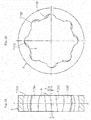
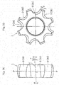
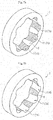
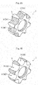
- FIG. 7A surface treatment for decreasing frictional resistance (sliding resistance) against the balls 4 was performed on parts (surfaces) of the outer joint member 2, on which the balls 4 as mating members repetitively roll, specifically, defined surfaces of the track grooves 7 (7A and 7B).
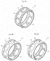
- the parts to be subjected to the surface treatment are shaded in FIG. 7A , and the same holds true also in FIG. 7B , FIG. 8A , FIG. 8B , and FIG. 9A to FIG. 9C to be referred to in the following description.
- the surface treatment there may be performed, for example, a process of forming lubricating films containing a solid lubricant (lubricant coating), barreling for forming numerous fine recessed portions to serve as a lubricating oil storage, a process of forming resin films (resin coating), and surface modification processes such as shot peening and shot blasting.
- a process of forming lubricating films containing a solid lubricant (lubricant coating) barreling for forming numerous fine recessed portions to serve as a lubricating oil storage
- a process of forming resin films (resin coating) resin films (resin coating)
- surface modification processes such as shot peening and shot blasting.
- the above-mentioned surface treatment may be performed on, in addition to or in place of the defined surfaces of the track groves 7 of the outer joint member 2, the spherical inner peripheral surface 6 of the outer joint member 2, which may repetitively come into sliding contact with the spherical outer peripheral surface 12 of of the cage 5, as illustrated in FIG. 7B .
- the above-mentioned surface treatment may be performed on, in addition to or in place of the defined surfaces of the track grooves 7 and/or the spherical inner peripheral surface 6 of the outer joint member 2, for example, the following parts.
- the surface treatment only needs to be performed on surfaces opposed to each other in the axial direction). In short, it is only necessary that the above-mentioned surface treatment be performed on at least one of the surfaces that (may) repetitively come into sliding contact with the mating members, and the surface to be subjected to the above-mentioned surface treatment may be selected as appropriate in consideration of required torque transmission efficiency and cost performance.
- the above-mentioned surface treatment is applied also to constant velocity universal joints 1 according to other embodiments described later, but description thereof is omitted for the sake of simplicity of description.
- the frictional resistance (sliding resistance) in contact portions between the components of the constant velocity universal joint 1 can be decreased. With this, the torque loss and the heat generation can be further suppressed, and even higher efficiency and an even longer life of the fixed type constant velocity universal joint 1 can be achieved.
- the above-mentioned surface treatment be performed on the surfaces to which great contact forces are repetitively applied, specifically, at least one surface selected from the group consisting of the defined surfaces (see FIG. 7A ) of the track grooves 7 of the outer joint member 2, the defined surfaces (see FIG. 8A ) of the track grooves 9 of the inner joint member 3, and the defined surfaces (see FIG. 9C ) of the pocket portions 5a of the cage 5.
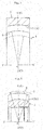
- FIG. 10 is a schematic sectional view of a propeller shaft comprising the fixed type constant velocity universal joint 1 described above.
- the propeller shaft 20 comprises the fixed type constant velocity universal joint 1, a shaft 22 comprising one axial end portion that is spline-coupled to a hole portion of the inner joint member 3, and a boot 21 mounted to an outer peripheral surface of the outer joint member 2 and an outer peripheral surface of the shaft 22 so as to prevent the grease sealed inside the joint as the lubricant from leaking to an outside.
- the shaft 22 comprises a large-diameter pipe portion 22a, and another fixed type or plunging type constant velocity universal joint (not shown) is coupled to the other axial end portion of the shaft 22.
- the boot 21 comprises a sealing ring 21a fixed to the outer peripheral surface of the outer joint member 2, and an elastic boot portion 21b comprising one end fixed to the sealing ring 21a and the other end mounted to the shaft 22 with a boot band 23.
- the sealing ring 21a of the boot 21 is fixed to the outer peripheral surface of the outer joint member 2, for example, by crimping.
- the propeller shaft 20 uses the fixed type constant velocity universal joint 1 according to the present invention, and hence it is possible to attain a propeller shaft that is further suppressed in torque loss and heat generation and enhanced in efficiency, and is also lightweight and compact.
- An automobile having the propeller shaft 20 mounted therein is excellent in torque transmission efficiency, and hence can be suppressed in fuel consumption.
- FIG. 11A is a partial sectional view of an outer joint member to be used in a fixed type constant velocity universal joint according to a second embodiment of the present invention.
- FIG. 11B is a partial sectional view of an inner joint member to be used in a fixed type constant velocity universal joint according to a third embodiment of the present invention.
- FIG. 11A is a partial sectional view of the outer joint member taken along the plane M (see FIG. 2A ) including the ball raceway center line X of the track groove 7A and the joint center O.
- FIG. 11B is a partial sectional view of the inner joint member taken along the plane Q (see FIG.
- the constant velocity universal joints according to the second and third embodiments are different from the fixed type constant velocity universal joint 1 according to the first embodiment described above mainly in that the curvature center of each of the track grooves (ball raceway center lines) is arranged at a position offset by "f" in a radial direction with respect to the joint axial line N-N (not offset in the axial direction with respect to the joint center O). That is, in the second and third embodiments, the curvature center of the ball raceway center line of each of the track grooves is offset by "f" in the radial direction in the joint center plane P including the perpendicular line K at the operating angle of 0°.
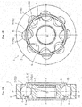
- FIG. 12A and FIG. 12B are illustrations of a fixed type constant velocity universal joint 1 according to a fourth embodiment of the present invention.
- the constant velocity universal joint 1 according to this embodiment is structurally different from the fixed type constant velocity universal joint 1 described above in that the number of the balls is set to six.
- the number of the balls is set to six as in this case, there are advantages in that the total number of components is smaller than that in of the case where the number of the balls is set to eight, that satisfactory processability and assembly efficiency of the members can be achieved, and that a load capacity can be increased in accordance with increase in size of the balls.
- the present invention is applied to the fixed type constant velocity universal joint comprising the eight or six balls.
- the present invention is also suitably applicable to a fixed type constant velocity universal joint comprising ten or twelve balls.
- the above description is directed to the case where the present invention is applied to the fixed type constant velocity universal joint having the track grooves arranged at a regular pitch in the peripheral direction.
- the present invention is also suitably applicable to a fixed type constant velocity universal joint having the track grooves arranged at an irregular pitch in the peripheral direction.
- the inclination angles ⁇ of the track grooves with respect to the joint axial line N-N are set equal to each other in all the track grooves, but the present invention is not limited thereto.
- the inclination angles y of the track grooves may be set unequal to each other. In short, it is only necessary that the inclination angles be set so that the axial forces of the balls are applied in a balanced manner as a whole to all the pockets of the cage.
- the present invention is applied to the fixed type constant velocity universal joint configured so that the track grooves and the balls are held in contact (angular contact) at a contact angle.
- the present invention is not limited thereto.
- the present invention is also suitably applicable to a fixed type constant velocity universal joint configured so that the track grooves and the balls are held in circular contact by forming the track grooves into an arc shape in horizontal cross section.
Landscapes
- Engineering & Computer Science (AREA)
- General Engineering & Computer Science (AREA)
- Mechanical Engineering (AREA)
- Rolling Contact Bearings (AREA)
Applications Claiming Priority (2)
| Application Number | Priority Date | Filing Date | Title |
|---|---|---|---|
| JP2013133809A JP2015010616A (ja) | 2013-06-26 | 2013-06-26 | 固定式等速自在継手 |
| PCT/JP2014/063853 WO2014208241A1 (ja) | 2013-06-26 | 2014-05-26 | 固定式等速自在継手 |
Publications (3)
| Publication Number | Publication Date |
|---|---|
| EP3015729A1 true EP3015729A1 (de) | 2016-05-04 |
| EP3015729A4 EP3015729A4 (de) | 2017-02-22 |
| EP3015729B1 EP3015729B1 (de) | 2020-01-15 |
Family
ID=52141593
Family Applications (1)
| Application Number | Title | Priority Date | Filing Date |
|---|---|---|---|
| EP14817418.8A Active EP3015729B1 (de) | 2013-06-26 | 2014-05-26 | Festes universelles gleichlaufgelenk |
Country Status (5)
| Country | Link |
|---|---|
| US (1) | US10066674B2 (de) |
| EP (1) | EP3015729B1 (de) |
| JP (1) | JP2015010616A (de) |
| CN (1) | CN105339692A (de) |
| WO (1) | WO2014208241A1 (de) |
Families Citing this family (1)
| Publication number | Priority date | Publication date | Assignee | Title |
|---|---|---|---|---|
| TWI687333B (zh) * | 2019-05-17 | 2020-03-11 | 陳鵬任 | 汽車前輪傳動轉向裝置 |
Family Cites Families (14)
| Publication number | Priority date | Publication date | Assignee | Title |
|---|---|---|---|---|
| JPS5969523A (ja) * | 1982-10-08 | 1984-04-19 | Matsushita Electric Ind Co Ltd | 流体軸受 |
| US6736729B2 (en) * | 2002-07-03 | 2004-05-18 | Gkn Automotive, Inc. | Constant velocity joint and method of making same |
| JP2004301314A (ja) * | 2003-04-01 | 2004-10-28 | Nsk Ltd | 転がり軸受 |
| WO2005028896A1 (de) * | 2003-08-22 | 2005-03-31 | Gkn Driveline Deutschland Gmbh | Kugelfestgelenk mit gedrehten bahnquerschnitten |
| DE102007023354B4 (de) | 2007-05-18 | 2009-10-01 | Gkn Driveline Deutschland Gmbh | Kugelgleichlaufverschiebegelenk mit geringen Verschiebekräften |
| JP2009250342A (ja) * | 2008-04-04 | 2009-10-29 | Ntn Corp | 等速自在継手 |
| JP5138449B2 (ja) * | 2008-04-08 | 2013-02-06 | Ntn株式会社 | 等速自在継手 |
| WO2009145035A1 (ja) | 2008-05-30 | 2009-12-03 | Ntn株式会社 | 固定型等速自在継手 |
| JP5101430B2 (ja) * | 2008-08-11 | 2012-12-19 | Ntn株式会社 | 固定式等速自在継手 |
| JP5420369B2 (ja) * | 2009-10-08 | 2014-02-19 | Ntn株式会社 | 固定式等速自在継手 |
| JP5340897B2 (ja) * | 2009-11-25 | 2013-11-13 | Ntn株式会社 | 固定式等速自在継手 |
| CN103429922B (zh) * | 2011-03-18 | 2016-06-08 | Ntn株式会社 | 等速万向联轴器 |
| WO2012165096A1 (ja) | 2011-05-30 | 2012-12-06 | Ntn株式会社 | 固定式等速自在継手 |
| CN202203295U (zh) * | 2011-08-28 | 2012-04-25 | 襄阳博亚精工装备股份有限公司 | 内外沟道表面涂覆复合层的球笼联轴器 |
-
2013
- 2013-06-26 JP JP2013133809A patent/JP2015010616A/ja active Pending
-
2014
- 2014-05-26 CN CN201480036637.4A patent/CN105339692A/zh active Pending
- 2014-05-26 EP EP14817418.8A patent/EP3015729B1/de active Active
- 2014-05-26 WO PCT/JP2014/063853 patent/WO2014208241A1/ja not_active Ceased
- 2014-05-26 US US14/899,856 patent/US10066674B2/en active Active
Non-Patent Citations (1)
| Title |
|---|
| See references of WO2014208241A1 * |
Also Published As
| Publication number | Publication date |
|---|---|
| US20160146260A1 (en) | 2016-05-26 |
| CN105339692A (zh) | 2016-02-17 |
| WO2014208241A1 (ja) | 2014-12-31 |
| US10066674B2 (en) | 2018-09-04 |
| EP3015729B1 (de) | 2020-01-15 |
| EP3015729A4 (de) | 2017-02-22 |
| JP2015010616A (ja) | 2015-01-19 |
Similar Documents
| Publication | Publication Date | Title |
|---|---|---|
| US10260569B2 (en) | Fixed-type constant velocity universal joint | |
| US9206855B2 (en) | Fixed type constant-velocity universal joint | |
| EP2530346B1 (de) | Verschiebbares Tripodegleichlaufgelenk für ein Fahrzeug | |
| EP2905491B1 (de) | Festes universelles gleichlaufgelenk | |
| JP6113459B2 (ja) | 固定式等速自在継手 | |
| JP2012017809A5 (de) | ||
| US9581206B2 (en) | Fixed type constant velocity universal joint | |
| US9551382B2 (en) | Fixed type constant velocity universal joint | |
| US20140073441A1 (en) | Fixed constant velocity universal joint | |
| EP3067582B1 (de) | Stationäres gleichlaufgelenk | |
| EP2003355B1 (de) | Fest stehendes, gleichförmig übersetzendes universalgelenk | |
| EP3015729B1 (de) | Festes universelles gleichlaufgelenk | |
| JP2009079684A (ja) | 固定式等速自在継手 | |
| JP6173675B2 (ja) | 固定式等速自在継手 | |
| WO2019003765A1 (ja) | 固定式等速自在継手 | |
| CN103917796B (zh) | 固定式等速万向联轴器 | |
| CN103917796A (zh) | 固定式等速万向联轴器 |
Legal Events
| Date | Code | Title | Description |
|---|---|---|---|
| PUAI | Public reference made under article 153(3) epc to a published international application that has entered the european phase |
Free format text: ORIGINAL CODE: 0009012 |
|
| 17P | Request for examination filed |
Effective date: 20160115 |
|
| AK | Designated contracting states |
Kind code of ref document: A1 Designated state(s): AL AT BE BG CH CY CZ DE DK EE ES FI FR GB GR HR HU IE IS IT LI LT LU LV MC MK MT NL NO PL PT RO RS SE SI SK SM TR |
|
| AX | Request for extension of the european patent |
Extension state: BA ME |
|
| DAX | Request for extension of the european patent (deleted) | ||
| A4 | Supplementary search report drawn up and despatched |
Effective date: 20170125 |
|
| RIC1 | Information provided on ipc code assigned before grant |
Ipc: F16D 3/224 20110101ALI20170119BHEP Ipc: F16D 3/223 20110101ALI20170119BHEP Ipc: F16D 3/20 20060101AFI20170119BHEP |
|
| GRAP | Despatch of communication of intention to grant a patent |
Free format text: ORIGINAL CODE: EPIDOSNIGR1 |
|
| STAA | Information on the status of an ep patent application or granted ep patent |
Free format text: STATUS: GRANT OF PATENT IS INTENDED |
|
| RIC1 | Information provided on ipc code assigned before grant |
Ipc: F16D 3/223 20110101ALI20190725BHEP Ipc: F16D 3/20 20060101AFI20190725BHEP Ipc: F16D 3/224 20110101ALI20190725BHEP |
|
| INTG | Intention to grant announced |
Effective date: 20190828 |
|
| GRAS | Grant fee paid |
Free format text: ORIGINAL CODE: EPIDOSNIGR3 |
|
| GRAA | (expected) grant |
Free format text: ORIGINAL CODE: 0009210 |
|
| STAA | Information on the status of an ep patent application or granted ep patent |
Free format text: STATUS: THE PATENT HAS BEEN GRANTED |
|
| AK | Designated contracting states |
Kind code of ref document: B1 Designated state(s): AL AT BE BG CH CY CZ DE DK EE ES FI FR GB GR HR HU IE IS IT LI LT LU LV MC MK MT NL NO PL PT RO RS SE SI SK SM TR |
|
| REG | Reference to a national code |
Ref country code: CH Ref legal event code: EP Ref country code: GB Ref legal event code: FG4D |
|
| REG | Reference to a national code |
Ref country code: IE Ref legal event code: FG4D |
|
| REG | Reference to a national code |
Ref country code: DE Ref legal event code: R096 Ref document number: 602014060128 Country of ref document: DE |
|
| REG | Reference to a national code |
Ref country code: AT Ref legal event code: REF Ref document number: 1225404 Country of ref document: AT Kind code of ref document: T Effective date: 20200215 |
|
| REG | Reference to a national code |
Ref country code: NL Ref legal event code: MP Effective date: 20200115 |
|
| REG | Reference to a national code |
Ref country code: LT Ref legal event code: MG4D |
|
| PG25 | Lapsed in a contracting state [announced via postgrant information from national office to epo] |
Ref country code: PT Free format text: LAPSE BECAUSE OF FAILURE TO SUBMIT A TRANSLATION OF THE DESCRIPTION OR TO PAY THE FEE WITHIN THE PRESCRIBED TIME-LIMIT Effective date: 20200607 Ref country code: NO Free format text: LAPSE BECAUSE OF FAILURE TO SUBMIT A TRANSLATION OF THE DESCRIPTION OR TO PAY THE FEE WITHIN THE PRESCRIBED TIME-LIMIT Effective date: 20200415 Ref country code: NL Free format text: LAPSE BECAUSE OF FAILURE TO SUBMIT A TRANSLATION OF THE DESCRIPTION OR TO PAY THE FEE WITHIN THE PRESCRIBED TIME-LIMIT Effective date: 20200115 Ref country code: FI Free format text: LAPSE BECAUSE OF FAILURE TO SUBMIT A TRANSLATION OF THE DESCRIPTION OR TO PAY THE FEE WITHIN THE PRESCRIBED TIME-LIMIT Effective date: 20200115 Ref country code: RS Free format text: LAPSE BECAUSE OF FAILURE TO SUBMIT A TRANSLATION OF THE DESCRIPTION OR TO PAY THE FEE WITHIN THE PRESCRIBED TIME-LIMIT Effective date: 20200115 |
|
| PG25 | Lapsed in a contracting state [announced via postgrant information from national office to epo] |
Ref country code: HR Free format text: LAPSE BECAUSE OF FAILURE TO SUBMIT A TRANSLATION OF THE DESCRIPTION OR TO PAY THE FEE WITHIN THE PRESCRIBED TIME-LIMIT Effective date: 20200115 Ref country code: SE Free format text: LAPSE BECAUSE OF FAILURE TO SUBMIT A TRANSLATION OF THE DESCRIPTION OR TO PAY THE FEE WITHIN THE PRESCRIBED TIME-LIMIT Effective date: 20200115 Ref country code: LV Free format text: LAPSE BECAUSE OF FAILURE TO SUBMIT A TRANSLATION OF THE DESCRIPTION OR TO PAY THE FEE WITHIN THE PRESCRIBED TIME-LIMIT Effective date: 20200115 Ref country code: GR Free format text: LAPSE BECAUSE OF FAILURE TO SUBMIT A TRANSLATION OF THE DESCRIPTION OR TO PAY THE FEE WITHIN THE PRESCRIBED TIME-LIMIT Effective date: 20200416 Ref country code: IS Free format text: LAPSE BECAUSE OF FAILURE TO SUBMIT A TRANSLATION OF THE DESCRIPTION OR TO PAY THE FEE WITHIN THE PRESCRIBED TIME-LIMIT Effective date: 20200515 Ref country code: BG Free format text: LAPSE BECAUSE OF FAILURE TO SUBMIT A TRANSLATION OF THE DESCRIPTION OR TO PAY THE FEE WITHIN THE PRESCRIBED TIME-LIMIT Effective date: 20200415 |
|
| REG | Reference to a national code |
Ref country code: DE Ref legal event code: R097 Ref document number: 602014060128 Country of ref document: DE |
|
| PG25 | Lapsed in a contracting state [announced via postgrant information from national office to epo] |
Ref country code: CZ Free format text: LAPSE BECAUSE OF FAILURE TO SUBMIT A TRANSLATION OF THE DESCRIPTION OR TO PAY THE FEE WITHIN THE PRESCRIBED TIME-LIMIT Effective date: 20200115 Ref country code: ES Free format text: LAPSE BECAUSE OF FAILURE TO SUBMIT A TRANSLATION OF THE DESCRIPTION OR TO PAY THE FEE WITHIN THE PRESCRIBED TIME-LIMIT Effective date: 20200115 Ref country code: RO Free format text: LAPSE BECAUSE OF FAILURE TO SUBMIT A TRANSLATION OF THE DESCRIPTION OR TO PAY THE FEE WITHIN THE PRESCRIBED TIME-LIMIT Effective date: 20200115 Ref country code: DK Free format text: LAPSE BECAUSE OF FAILURE TO SUBMIT A TRANSLATION OF THE DESCRIPTION OR TO PAY THE FEE WITHIN THE PRESCRIBED TIME-LIMIT Effective date: 20200115 Ref country code: LT Free format text: LAPSE BECAUSE OF FAILURE TO SUBMIT A TRANSLATION OF THE DESCRIPTION OR TO PAY THE FEE WITHIN THE PRESCRIBED TIME-LIMIT Effective date: 20200115 Ref country code: EE Free format text: LAPSE BECAUSE OF FAILURE TO SUBMIT A TRANSLATION OF THE DESCRIPTION OR TO PAY THE FEE WITHIN THE PRESCRIBED TIME-LIMIT Effective date: 20200115 Ref country code: SM Free format text: LAPSE BECAUSE OF FAILURE TO SUBMIT A TRANSLATION OF THE DESCRIPTION OR TO PAY THE FEE WITHIN THE PRESCRIBED TIME-LIMIT Effective date: 20200115 Ref country code: SK Free format text: LAPSE BECAUSE OF FAILURE TO SUBMIT A TRANSLATION OF THE DESCRIPTION OR TO PAY THE FEE WITHIN THE PRESCRIBED TIME-LIMIT Effective date: 20200115 |
|
| REG | Reference to a national code |
Ref country code: AT Ref legal event code: MK05 Ref document number: 1225404 Country of ref document: AT Kind code of ref document: T Effective date: 20200115 |
|
| PLBE | No opposition filed within time limit |
Free format text: ORIGINAL CODE: 0009261 |
|
| STAA | Information on the status of an ep patent application or granted ep patent |
Free format text: STATUS: NO OPPOSITION FILED WITHIN TIME LIMIT |
|
| 26N | No opposition filed |
Effective date: 20201016 |
|
| PG25 | Lapsed in a contracting state [announced via postgrant information from national office to epo] |
Ref country code: LI Free format text: LAPSE BECAUSE OF NON-PAYMENT OF DUE FEES Effective date: 20200531 Ref country code: AT Free format text: LAPSE BECAUSE OF FAILURE TO SUBMIT A TRANSLATION OF THE DESCRIPTION OR TO PAY THE FEE WITHIN THE PRESCRIBED TIME-LIMIT Effective date: 20200115 Ref country code: IT Free format text: LAPSE BECAUSE OF FAILURE TO SUBMIT A TRANSLATION OF THE DESCRIPTION OR TO PAY THE FEE WITHIN THE PRESCRIBED TIME-LIMIT Effective date: 20200115 Ref country code: CH Free format text: LAPSE BECAUSE OF NON-PAYMENT OF DUE FEES Effective date: 20200531 Ref country code: MC Free format text: LAPSE BECAUSE OF FAILURE TO SUBMIT A TRANSLATION OF THE DESCRIPTION OR TO PAY THE FEE WITHIN THE PRESCRIBED TIME-LIMIT Effective date: 20200115 |
|
| PG25 | Lapsed in a contracting state [announced via postgrant information from national office to epo] |
Ref country code: PL Free format text: LAPSE BECAUSE OF FAILURE TO SUBMIT A TRANSLATION OF THE DESCRIPTION OR TO PAY THE FEE WITHIN THE PRESCRIBED TIME-LIMIT Effective date: 20200115 Ref country code: SI Free format text: LAPSE BECAUSE OF FAILURE TO SUBMIT A TRANSLATION OF THE DESCRIPTION OR TO PAY THE FEE WITHIN THE PRESCRIBED TIME-LIMIT Effective date: 20200115 |
|
| REG | Reference to a national code |
Ref country code: BE Ref legal event code: MM Effective date: 20200531 |
|
| GBPC | Gb: european patent ceased through non-payment of renewal fee |
Effective date: 20200526 |
|
| PG25 | Lapsed in a contracting state [announced via postgrant information from national office to epo] |
Ref country code: LU Free format text: LAPSE BECAUSE OF NON-PAYMENT OF DUE FEES Effective date: 20200526 |
|
| PG25 | Lapsed in a contracting state [announced via postgrant information from national office to epo] |
Ref country code: IE Free format text: LAPSE BECAUSE OF NON-PAYMENT OF DUE FEES Effective date: 20200526 Ref country code: GB Free format text: LAPSE BECAUSE OF NON-PAYMENT OF DUE FEES Effective date: 20200526 |
|
| PG25 | Lapsed in a contracting state [announced via postgrant information from national office to epo] |
Ref country code: BE Free format text: LAPSE BECAUSE OF NON-PAYMENT OF DUE FEES Effective date: 20200531 |
|
| PG25 | Lapsed in a contracting state [announced via postgrant information from national office to epo] |
Ref country code: TR Free format text: LAPSE BECAUSE OF FAILURE TO SUBMIT A TRANSLATION OF THE DESCRIPTION OR TO PAY THE FEE WITHIN THE PRESCRIBED TIME-LIMIT Effective date: 20200115 Ref country code: MT Free format text: LAPSE BECAUSE OF FAILURE TO SUBMIT A TRANSLATION OF THE DESCRIPTION OR TO PAY THE FEE WITHIN THE PRESCRIBED TIME-LIMIT Effective date: 20200115 Ref country code: CY Free format text: LAPSE BECAUSE OF FAILURE TO SUBMIT A TRANSLATION OF THE DESCRIPTION OR TO PAY THE FEE WITHIN THE PRESCRIBED TIME-LIMIT Effective date: 20200115 |
|
| PG25 | Lapsed in a contracting state [announced via postgrant information from national office to epo] |
Ref country code: MK Free format text: LAPSE BECAUSE OF FAILURE TO SUBMIT A TRANSLATION OF THE DESCRIPTION OR TO PAY THE FEE WITHIN THE PRESCRIBED TIME-LIMIT Effective date: 20200115 Ref country code: AL Free format text: LAPSE BECAUSE OF FAILURE TO SUBMIT A TRANSLATION OF THE DESCRIPTION OR TO PAY THE FEE WITHIN THE PRESCRIBED TIME-LIMIT Effective date: 20200115 |
|
| REG | Reference to a national code |
Ref country code: FR Ref legal event code: PLFP Year of fee payment: 10 |
|
| PGFP | Annual fee paid to national office [announced via postgrant information from national office to epo] |
Ref country code: FR Payment date: 20240328 Year of fee payment: 11 |
|
| PGFP | Annual fee paid to national office [announced via postgrant information from national office to epo] |
Ref country code: DE Payment date: 20240328 Year of fee payment: 11 |
|
| REG | Reference to a national code |
Ref country code: DE Ref legal event code: R119 Ref document number: 602014060128 Country of ref document: DE |
|
| PG25 | Lapsed in a contracting state [announced via postgrant information from national office to epo] |
Ref country code: DE Free format text: LAPSE BECAUSE OF NON-PAYMENT OF DUE FEES Effective date: 20251202 |
|
| PG25 | Lapsed in a contracting state [announced via postgrant information from national office to epo] |
Ref country code: FR Free format text: LAPSE BECAUSE OF NON-PAYMENT OF DUE FEES Effective date: 20250531 |