EP3016076A1 - Procédé et appareil permettant de retirer des valeurs aberrantes à partir d'une vue principale d'une scène pendant la reconstruction d'une scène 3D - Google Patents
Procédé et appareil permettant de retirer des valeurs aberrantes à partir d'une vue principale d'une scène pendant la reconstruction d'une scène 3D Download PDFInfo
- Publication number
- EP3016076A1 EP3016076A1 EP14306750.2A EP14306750A EP3016076A1 EP 3016076 A1 EP3016076 A1 EP 3016076A1 EP 14306750 A EP14306750 A EP 14306750A EP 3016076 A1 EP3016076 A1 EP 3016076A1
- Authority
- EP
- European Patent Office
- Prior art keywords
- pixel
- main view
- view
- neighboring
- point
- Prior art date
- Legal status (The legal status is an assumption and is not a legal conclusion. Google has not performed a legal analysis and makes no representation as to the accuracy of the status listed.)
- Withdrawn
Links
Images





Classifications
-
- G—PHYSICS
- G06—COMPUTING OR CALCULATING; COUNTING
- G06T—IMAGE DATA PROCESSING OR GENERATION, IN GENERAL
- G06T15/00—Three-dimensional [3D] image rendering
- G06T15/005—General purpose rendering architectures
-
- G—PHYSICS
- G06—COMPUTING OR CALCULATING; COUNTING
- G06T—IMAGE DATA PROCESSING OR GENERATION, IN GENERAL
- G06T17/00—Three-dimensional [3D] modelling for computer graphics
-
- G—PHYSICS
- G06—COMPUTING OR CALCULATING; COUNTING
- G06T—IMAGE DATA PROCESSING OR GENERATION, IN GENERAL
- G06T7/00—Image analysis
- G06T7/30—Determination of transform parameters for the alignment of images, i.e. image registration
-
- G—PHYSICS
- G06—COMPUTING OR CALCULATING; COUNTING
- G06T—IMAGE DATA PROCESSING OR GENERATION, IN GENERAL
- G06T2207/00—Indexing scheme for image analysis or image enhancement
- G06T2207/10—Image acquisition modality
- G06T2207/10028—Range image; Depth image; 3D point clouds
Definitions
- the invention relates to a method and an apparatus for 3D scene reconstruction.
- the invention relates to a method and an apparatus for removing outliers from a main view of a scene during 3D reconstruction of a scene from multiple views of the scene.
- MVS multi-view stereo
- a dense model can be created as follows.
- the light from a 3D point in the scene hits the two camera sensors at different locations. If these locations are known, the depth of the point can be computed by triangulation.
- the process of finding such a pixel correspondence is referred to as disparity estimation.
- Applying this principle to all pixels leads to a dense 3D point cloud.
- one image together with the camera pose and parameters and the depth information are referred to as a "view”. Note that the depth estimates of a view need not necessarily be derived from a stereo frame, but could also be obtained from a time-of-flight sensor or a structured-light sensor, for example.
- the depth information of the corresponding pixel in the main view is kept if there is agreement for n ⁇ ⁇ neighboring views, where ⁇ is a free parameter. This approach does not distinguish between conflicts and possible occlusions. If ⁇ ⁇ N , depth estimates may be kept when there is no agreement due to an occlusion, but also if there is strongly contradicting information from one or more side views. Furthermore, it is questionable whether or not the distance computed relative to a depth is the best measure for the comparison.
- the algorithm starts with the smallest depth estimate and evaluates a stability function related to occlusions and free-space-violations of the corresponding 3D point.
- the 3D point related to the current depth hypothesis needs to be projected into all N neighboring views.
- the underlying idea of the stability function is that a free space violation suggests that the depth of the pixel of the main view is underestimated, while an occlusion suggests that it is overestimated.
- the depth of a pixel is called stable when there is as much evidence that the depth is overestimated as for it being underestimated.
- the minimal stable depth hypothesis is chosen, and support for it is computed from the confidence of depth estimates which agree with it. Here agreement is based on the relative distance as above.
- a depth estimate is fused with all depth estimates agreeing with it.
- the confidence is the sum of the confidences of all agreeing depth estimates minus the confidences of the conflicting ones.
- a problem of the first algorithm is that it is questionable whether or not free space violations and occlusions really indicate the under- and overestimation of the original pixel's depth. Furthermore, a depth might be called stable even when there are strong conflicts with respect to some neighboring views.
- a disadvantage of both algorithms is that the collection of all pixels from the neighboring views which project into the same pixel in the main view is computationally much more demanding than projecting from the main view into the neighboring views. Also, in contrast to the approaches of E. Tola et al. and Shen, generally many more (up to N 2 ) than N projections from one view into another one are required, which are computationally costly.
- a method for removing outliers from a main view of a scene during 3D reconstruction of a scene from multiple views of the scene comprises:
- a computer readable storage medium has stored therein instructions enabling removing outliers from a main view of a scene during 3D reconstruction of a scene from multiple views of the scene, which, when executed by a computer, cause the computer to:
- the 3D reconstruction from a large set of views is considered. These views are, for example, obtained from a stereo-video sequence. Outliers are removed from a main view by projecting the 3D points of the main view into N neighboring views. Information on the spatial consistency from several neighboring views is consistently combined, properly taking into account occlusions and conflicts. To this end the distance of each of the corresponding 3D points in the neighboring views to the 3D point of the main view are compared with a defined distance threshold.
- the proposed solution will generally reject more pixels than prior art solutions, as it disposes of nearly all bad depth estimates. However, since in this setting there is an abundance of data, it is sufficient to keep only very reliable 3D points. Agreement of 3D points is judged based on the absolute distance, which is a stricter agreement criterion than that based on the relative distance because it does not get weaker with increasing depth. As a result, a fixed spatial precision is obtained.
- a flag with a first value is assigned when the 3D point in the main view and a projected 3D point in a neighboring view are in agreement
- a flag with a second value is assigned when a conflict exists between the 3D point in the main view and a projected 3D point in a neighboring view
- a flag with a third value is assigned when the comparison cannot be performed or when a clear decision cannot be made.
- the 3D point of a neighboring view is considered to be in agreement with that of the main view if their distance is below a defined distance threshold. If the distance exceeds the threshold, and the 3D point of the main view is closer to the camera center of the neighboring view than the 3D point seen by the neighboring view, this is a clear conflict, and the "bad" flag is assigned.
- the flag "undecided” summarizes several cases. One case is that no depth information is available for a pixel in a neighboring view hit by projecting the 3D point of the pixel of the main view. Another case is that projecting the 3D point of the pixel of the main view into a neighboring view does not hit the neighboring view.
- a deviation of the distances might be due to an occlusion, i.e. the distance threshold is exceeded, but the 3D point seen by the neighboring view is closer to its camera center than the 3D point of the main view.
- a deviation of the distances might be due to an occlusion, i.e. the distance threshold is exceeded, but the 3D point seen by the neighboring view is closer to its camera center than the 3D point of the main view.
- the pixel in the main view is rejected as an outlier if the number of flags with the second value is above a conflict threshold or if the number of flags with the first value is below an agreement threshold.
- a pixel of the main view is rejected if there are too many "bad” results or not enough "good” results. In this way pixels for which strictly contradicting information is given from the comparison with a neighboring view are reliably rejected.
- the flag with the third value is changed to a flag with the second value when the distance is above the defined distance threshold but below a sum of depth errors of the pixel in the main view and the pixel in the neighboring view hit by projecting the 3D point of the pixel of the main view.
- a further distance threshold based on the depth estimation error is used. If the distance is in between the two thresholds, the precision requirement is violated, but taking into account the error of the disparity estimation, the true depth of the 3D point in the main view may actually be smaller than that of the 3D point in the neighboring view. Hence in this situation it is not safe to judge that an occlusion is present.
- an additional consistency check is performed when a flag with the first value is assigned to the pixel.
- the flag with the first value is then changed to a flag with the second value when the additional consistency check fails.
- the additional check is used to detect bad depth estimates, which cannot be detected by spatial consistency checks in the presence of systematically wrong depth estimates produced by typical disparity estimators.
- the check is simple and fast because the computationally costly 3D projections from the main view into the neighboring views have already been carried out for the spatial consistency checks.
- the additional consistency check compares a property of the pixel in the main view and a property of the pixel in the neighboring view hit by projecting the 3D point of the pixel of the main view. If the two views are really seeing the same 3D point, any other information obtained for that point from the two views should agree as well. For instance, the image intensity or the color of the pixel could be compared to that of the pixel hit in the neighboring view. Alternatively, an intensity averaged for a window around the pixel or a color averaged for a window around the pixel can be compared. This allows handling luminosity changes that may occur due to specular surfaces when the two images were taken at a larger distance of the cameras, even though the same camera was used.
- the additional consistency check uses a normalized cross-correlation between a window centered at the pixel in the main view and a window centered at the pixel in the neighboring view hit by projecting the 3D point of the pixel of the main view. This approach further increases the robustness with respect to luminosity changes as well as to image sensor noise.
- the sequence in case of a sequence of views, is divided into distinct subsets, wherein for each subset one view is selected as a main view, whereas the remaining views are selected as neighboring views.
- a view of the sequence serves as a main view, but also as a neighboring view for another view of the sequence.
- the proposed solution allows using every view not only as a main view, which is cleaned, but also as a neighboring view, it is ideally suited for sequences of views.
- the proposed approach is formulated for views without considering the origin of the depth information. It is hence not only suitable for a video-sequence of stereo-images.
- the results could be applied to any dataset where a sequence of images with depth information is available, e.g. a monocular video-sequence or a collection of images.
- the proposed approach aims at removing outliers of a view of a stereo-sequence through the comparison with N neighboring views.
- a moving stereo-camera one can usually choose a neighborhood of views on both sides of a main view by considering views at slightly earlier and slightly later time instances. In this case, objects which are occluded from one side are typically not occluded from the other side.
- the simplest situation of this type is depicted in Fig. 1 . Note, however, that the present approach is applicable to other situations as well, even when there is only a single neighboring view, for instance.
- each triangle represents a view as defined in the background section, where "nb-view" refers to a neighboring view.
- the 3D point X m for a pixel from the main view is projected into the two neighboring views. From the depths of the pixels hit there, the 3D points X 1 and X 2 are computed.
- the distance of a 3D point with respect to the camera center of the nb-view i is denoted by D i .
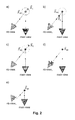
- Fig. 2 For each pixel of the main view, one of five different results is obtained from the comparison with one neighboring view which are illustrated in Fig. 2 .
- the circles around the 3D point X m depict the distance bound ⁇ dist . If X m and X i are in agreement, the corresponding pixel of the main view is flagged as "good” ( Fig. 2a )). If the distance bound is violated, then the pixel is flagged either as "bad” if there is a clear contradiction ( Fig. 2c )) or as "occluded” if the deviation might be due to an occlusion ( Fig. 2b )), i.e. there might be some object preventing the neighboring view from seeing the 3D point X m .
- a pixel is flagged as "no depth” if there is no depth information at the pixel hit in the neighboring view ( Fig. 2d )). Introducing this flag is useful mainly because of two reasons. Firstly, the disparity estimator may judge that a depth estimate is unreliable, or secondly, the neighboring view may have been cleaned already in an iterative strategy, and the pixel's depth may have been rejected as unreliable at this stage. This will be explained later during the discussion of iterative strategies. Finally, a pixel is flagged as "out” if the re-projection does not hit the neighboring view ( Fig. 2e )).
- the uncertainty ⁇ d may be used as a free parameter here.
- the second distance bound depends on the estimated error ⁇ d of the disparity estimation. This situation is illustrated in Fig. 3 , where the thin circle around X m depicts the distance threshold ⁇ dist . The thicker circles have a radius corresponding to the estimated depth error ⁇ D .
- X 2 is far enough away so that the original pixel receives the flag "occluded" from the comparison with the neighboring view 2, while X 1 is so close that the original pixel is flagged "bad” from the comparison with view 1.
- the depth error is valid only in the direction of the pixel-ray, but it is also used for the other directions for simplicity.
- N flags for every pixel. Each flag is "good”, “bad”, or "undecided". According to the proposed approach a pixel is rejected if the number of "bad" flags is above a threshold ⁇ bad or if the number of "good” flags is below a threshold ⁇ good . Note that the "undecided" flag allows to keep occluded pixels. Generally, a small ⁇ bad will be chosen in order to take into account contradictions properly. Note that in this way also bad depth estimates may be removed before they are used for a comparison with another view in an iterative strategy, as will be described later. However, introducing the possibility of keeping a pixel although there are contradicting results is useful for a larger N because the contradictions may be due to faulty disparity estimates in the neighboring views, not in the main view.
- a disparity estimator misjudges the depth and hence the 3D point in such a way that the bad estimate is consistent with the estimated 3D point from different viewpoints. For block-matching algorithms, for instance, this can happen when the object as seen in the image is of a similar size as the window size used for the disparity estimation.
- This situation can be detected by performing additional consistency checks using other information channels for the pixels with "good” spatial consistency. This may turn a "good” flag into a “bad” flag.
- One may compare direct image information such as pixel intensities or colors.
- additional information from the image neighborhoods of the pixels can be processed to compute the normalized cross-correlation (NCC), for instance.
- NCC normalized cross-correlation
- any other information could be compared as well, such as, for instance, normal vectors of the estimated surface, which some disparity estimators provide.
- a "good” flag remains “good”. If it fails, it is changed to "bad”.
- the situation is illustrated in Fig. 4 .
- the true surface is the bold line.
- the surface which is falsely estimated by both the main view as well as the neighboring view is the dashed line. This can happen when the size of the object in the images is comparable to or smaller than the window size of the block matching algorithm. In this case it can happen that the estimated depth of the part where the object is planar is interpolated with the estimated depth of the part where it is curved, so that the protruding object is estimated as being less protruding than it actually is. Since the two views see different parts of the surface, the secondary test can help to detect the false depth estimates. In the illustration, the intensity seen from the left view is black while the one seen by the right view is light grey.
- the threshold ⁇ int is a free parameter. Since a moving camera is considered, such a test is already sufficient if the neighboring image was recorded at a close-by instant in time, as in this situation the camera centers are close and the viewing directions are similar.
- NCC normalized cross-correlation
- the NCC takes values in between -1 and 1. It is close to 1 if the two patches agree well. Hence one can call a pixel's depth estimate consistent with the neighboring view i if NCC p ⁇ i p ⁇ m ⁇ ⁇ NCC , where ⁇ NCC is a free parameter.
- a further improvement can be achieved by projecting the window from the main view into the neighboring view to properly take slanted surfaces into account.
- Pairs of images were grouped to form stereo frames for testing purposes.
- the setting of Fig. 1 was considered, where the main stereo frame comprised the images (5,4) and the neighboring stereo frames were made from the pairs (3,2) and (7,6).
- a disparity estimator was applied, which was developed based on the methods from N. Atzpadin et al.: "Stereo Analysis by Hybrid Recursive Matching for Real-Time Immersive Video Conferencing", IEEE Transactions on Circuits and Systems for Video Technology, Vol. 14 (2004), pp. 321-334 , and M.
- Fig. 5a) and Fig. 5c form a view.
- the disparity estimation was performed on downscaled images of size 768 ⁇ 512.
- the situation described with reference to Fig. 4 occurs, for example, for the protruding small round ornament on the fountain marked in Fig. 5a ).
- Point clouds were compared to the ground truth following the approach by S. Shen mentioned in the background of the invention. For each pixel of the main view the 3D point was compared with the closest 3D point of the ground truth along the ray. In order to be able to compare the present results and those of S. Shen, the relative depth deviation
- D gt was computed.
- D gt is the true depth and D est the estimated depth.
- Depth estimates were considered to be erroneous when this deviation was larger than 1%.
- Fig. 6 shows a histogram of relative deviations (keeping the sign of the difference) of the estimated 3D point cloud from the ground truth. The comparison with the ground truth was performed for the original depth map.
- Fig. 7 for each pixel this deviation is plotted in light gray for values not larger than 1%, where a lighter gray corresponds to a smaller relative deviation. Dark gray corresponds to pixels where the relative deviation is larger than 1%. Pixels which do not have a depth estimate or for which no ground truth depth exists are depicted in black as before.
- Quality indicators of interest are the standard deviation of the deviation histograms, the percentage of error pixels, and the number of surviving pixels.
- Fig. 9 The remaining pixels and grayscale-encoded relative deviations for the first strategy already mentioned above are shown in Fig. 9 , i.e. the strategy based on spatial consistency only.
- Fig. 10 to Fig. 13 depict the remaining pixels and grayscale-encoded relative deviations from the ground truth for the remaining four tested strategies documented in Table 1.
- Fig. 10 visualizes the results of the second setting, namely the strategy based on spatial consistency and post-processing of occluded pixels.
- the results for the third setting i.e. the strategy based on spatial consistency with an intensity based consistency check, are depicted in Fig. 11 .
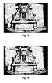
- Fig. 12 shows the results of the fourth setting, namely the strategy based on spatial consistency with an intensity based consistency check with luminosity correction.
- Fig. 13 depicts the results of the strategy based on spatial consistency with an NCC check.
- Fig. 14 the performances of the different strategies are compared for the protruding ornament marked in Fig. 5a ). Depicted are a detail of the image of Fig. 5a ) ( Fig. 14a) ), a comparison of the original point cloud with the ground truth ( Fig. 14b) ), the result of the plain spatial consistency based strategy ( Fig. 14c) ), results of the strategy with intensity check ( Fig. 14d) ), results of the strategy with intensity check with luminosity correction ( Fig. 14e) ), and results of the strategy with NCC check ( Fig. 14f) ). Note that all secondary consistency checks help to reject bad pixels not detected by the spatial consistency checks. The test based on the intensity corrected by the luminosity seems to reject the most additional bad pixels in the center. However, the NCC based test rejects fewer well-estimated pixels on the plane from which the ornament protrudes.
- a main view can be chosen, which is cleaned using the views of the subset as a neighborhood.
- a view may be used as a main view, but also as a neighboring view for the cleaning of a different view.
- two possible iterative strategies for the outlier removal shall be described.
- Fig. 15 depicts a sketch of an iterative strategy where the view captured at time step t is firstly cleaned itself and in the next step acts as a neighboring view.
- the views could stem from a stereo-camera sequence where the camera moves from left to right.
- the time steps are indicated below the views.
- each view is cleaned using its neighborhood.
- the initial views without removed outliers are cleaned once again, but now comparing to the cleaned neighboring views. In this way, only reliable neighboring information is used for the outlier removal.
- Fig. 16 schematically illustrates one embodiment of a method for removing outliers from a main view of a scene during 3D reconstruction of a scene from multiple views of the scene.
- a 3D point of a pixel of the main view is projected 10 into neighboring views.
- the distance of each of the projected 3D points in the neighboring views to the 3D point of the main view is compared 11 with a defined distance threshold. Based on this comparison, flags are assigned 12 to the pixel in the main view. Depending on values of the flags the pixel in the main view is rejected 13 as an outlier.
- FIG. 17 One embodiment of an apparatus 20 configured to perform the method according to the invention is schematically depicted in Fig. 17 .
- the apparatus 20 has an input 21 for receiving multiple views of a scene, e.g. from a network (not shown) or a storage unit 22.
- a 3D projection unit 23 projects 10 a 3D point of a pixel of the main view into neighboring views.
- a comparator 24 compares 11 the distance of each of the projected 3D points in the neighboring views to the 3D point of the main view with a defined distance threshold. Based on the comparison, a flagging unit 25 assigns 12 flags to the pixel in the main view. Finally, depending on values of the flags, a rejecting unit 26 rejects 13 the pixel in the main view as an outlier.
- the result obtained by the rejecting unit 26 is preferably made available via an output 27.
- the output 27 may also be combined with the input 21 into a single bidirectional interface.
- the different units 23, 24, 25, 26 may likewise be fully or partially combined into a single unit or implemented as software running on a processor.
- FIG. 18 Another embodiment of an apparatus 30 configured to perform the method according to the invention is schematically illustrated in Fig. 18 .
- the apparatus 30 comprises a processing device 31 and a memory device 32 storing instructions that, when executed, cause the apparatus to perform steps according to one of the described methods.
- the processing device 31 can be a processor adapted to perform the steps according to one of the described methods.
- said adaptation comprises that the processor is configured, e.g. programmed, to perform steps according to one of the described methods.
Landscapes
- Engineering & Computer Science (AREA)
- Physics & Mathematics (AREA)
- General Physics & Mathematics (AREA)
- Theoretical Computer Science (AREA)
- Computer Graphics (AREA)
- Geometry (AREA)
- Software Systems (AREA)
- Computer Vision & Pattern Recognition (AREA)
- Image Processing (AREA)
- Testing, Inspecting, Measuring Of Stereoscopic Televisions And Televisions (AREA)
- Image Analysis (AREA)
Priority Applications (3)
| Application Number | Priority Date | Filing Date | Title |
|---|---|---|---|
| EP14306750.2A EP3016076A1 (fr) | 2014-10-31 | 2014-10-31 | Procédé et appareil permettant de retirer des valeurs aberrantes à partir d'une vue principale d'une scène pendant la reconstruction d'une scène 3D |
| EP15190339.0A EP3016077A1 (fr) | 2014-10-31 | 2015-10-19 | Procédé et appareil permettant de retirer des valeurs aberrantes à partir d'une vue principale d'une scène pendant la reconstruction d'une scène 3d |
| US14/929,325 US9792719B2 (en) | 2014-10-31 | 2015-10-31 | Method and apparatus for removing outliers from a main view of a scene during 3D scene reconstruction |
Applications Claiming Priority (1)
| Application Number | Priority Date | Filing Date | Title |
|---|---|---|---|
| EP14306750.2A EP3016076A1 (fr) | 2014-10-31 | 2014-10-31 | Procédé et appareil permettant de retirer des valeurs aberrantes à partir d'une vue principale d'une scène pendant la reconstruction d'une scène 3D |
Publications (1)
| Publication Number | Publication Date |
|---|---|
| EP3016076A1 true EP3016076A1 (fr) | 2016-05-04 |
Family
ID=51951754
Family Applications (2)
| Application Number | Title | Priority Date | Filing Date |
|---|---|---|---|
| EP14306750.2A Withdrawn EP3016076A1 (fr) | 2014-10-31 | 2014-10-31 | Procédé et appareil permettant de retirer des valeurs aberrantes à partir d'une vue principale d'une scène pendant la reconstruction d'une scène 3D |
| EP15190339.0A Withdrawn EP3016077A1 (fr) | 2014-10-31 | 2015-10-19 | Procédé et appareil permettant de retirer des valeurs aberrantes à partir d'une vue principale d'une scène pendant la reconstruction d'une scène 3d |
Family Applications After (1)
| Application Number | Title | Priority Date | Filing Date |
|---|---|---|---|
| EP15190339.0A Withdrawn EP3016077A1 (fr) | 2014-10-31 | 2015-10-19 | Procédé et appareil permettant de retirer des valeurs aberrantes à partir d'une vue principale d'une scène pendant la reconstruction d'une scène 3d |
Country Status (2)
| Country | Link |
|---|---|
| US (1) | US9792719B2 (fr) |
| EP (2) | EP3016076A1 (fr) |
Cited By (1)
| Publication number | Priority date | Publication date | Assignee | Title |
|---|---|---|---|---|
| CN111127622A (zh) * | 2019-11-25 | 2020-05-08 | 浙江大学 | 基于图像分割的三维点云离群点剔除方法 |
Families Citing this family (14)
| Publication number | Priority date | Publication date | Assignee | Title |
|---|---|---|---|---|
| US9412034B1 (en) * | 2015-01-29 | 2016-08-09 | Qualcomm Incorporated | Occlusion handling for computer vision |
| EP4567734A3 (fr) | 2016-04-12 | 2025-07-30 | Quidient, LLC | Moteur de reconstruction de scènes quotidiennes |
| US10482621B2 (en) * | 2016-08-01 | 2019-11-19 | Cognex Corporation | System and method for improved scoring of 3D poses and spurious point removal in 3D image data |
| US10074160B2 (en) * | 2016-09-30 | 2018-09-11 | Disney Enterprises, Inc. | Point cloud noise and outlier removal for image-based 3D reconstruction |
| CN109242901B (zh) * | 2017-07-11 | 2021-10-22 | 深圳市道通智能航空技术股份有限公司 | 应用于三维相机的图像校准方法和装置 |
| CN119135920A (zh) | 2018-05-02 | 2024-12-13 | 奎蒂安特有限公司 | 用于处理具有几乎无限细节的场景的编解码器 |
| JP7179515B2 (ja) * | 2018-07-13 | 2022-11-29 | キヤノン株式会社 | 装置、制御方法、及びプログラム |
| US10878299B2 (en) | 2018-09-12 | 2020-12-29 | Cognex Corporation | Methods and apparatus for testing multiple fields for machine vision |
| US10825199B2 (en) | 2018-09-12 | 2020-11-03 | Cognex Corporation | Methods and apparatus for processing image data for machine vision |
| US10846563B2 (en) * | 2018-09-12 | 2020-11-24 | Cognex Corporation | Methods and apparatus for generating a dense field of three dimensional data for machine vision |
| US11841438B2 (en) | 2019-09-30 | 2023-12-12 | Zoox, Inc. | Power control of sensors using multiple exposures |
| US11726186B2 (en) * | 2019-09-30 | 2023-08-15 | Zoox, Inc. | Pixel filtering using multiple exposures |
| EP4273801A1 (fr) | 2022-05-06 | 2023-11-08 | Applications Mobiles Overview Inc. | Système et procédé d'extraction d'un objet d'intérêt à partir d'un nuage de points 3d |
| CN118224991B (zh) * | 2024-04-18 | 2025-03-11 | 中国长江三峡集团有限公司 | 隧洞围岩的变形分析方法、装置、设备及存储介质 |
Family Cites Families (11)
| Publication number | Priority date | Publication date | Assignee | Title |
|---|---|---|---|---|
| US6363170B1 (en) | 1998-04-30 | 2002-03-26 | Wisconsin Alumni Research Foundation | Photorealistic scene reconstruction by voxel coloring |
| US6990228B1 (en) | 1999-12-17 | 2006-01-24 | Canon Kabushiki Kaisha | Image processing apparatus |
| US7027642B2 (en) | 2000-04-28 | 2006-04-11 | Orametrix, Inc. | Methods for registration of three-dimensional frames to create three-dimensional virtual models of objects |
| JP2003269928A (ja) | 2002-03-12 | 2003-09-25 | Nec Corp | 3次元形状計測方法および装置ならびにプログラム |
| US7292735B2 (en) | 2004-04-16 | 2007-11-06 | Microsoft Corporation | Virtual image artifact detection |
| KR100931311B1 (ko) | 2006-12-04 | 2009-12-11 | 한국전자통신연구원 | 프레임 간 깊이 연속성 유지를 위한 깊이 추정 장치 및 그방법 |
| KR101310213B1 (ko) | 2009-01-28 | 2013-09-24 | 한국전자통신연구원 | 깊이 영상의 품질 개선 방법 및 장치 |
| EP2559256A4 (fr) | 2010-04-14 | 2015-08-26 | Ericsson Telefon Ab L M | Procédés et agencements pour représentation de scène 3d |
| KR101669840B1 (ko) | 2010-10-21 | 2016-10-28 | 삼성전자주식회사 | 다시점 비디오로부터 일관성 있는 변이를 추정하는 변이 추정 시스템 및 방법 |
| WO2013062944A1 (fr) | 2011-10-26 | 2013-05-02 | The Regents Of The University Of California | Procédé de synthèse multi-vues et dispositifs d'affichage avec cohérence spatiale et inter-vues |
| KR20130047822A (ko) * | 2011-11-01 | 2013-05-09 | 삼성전자주식회사 | 영상 처리 장치 및 방법 |
-
2014
- 2014-10-31 EP EP14306750.2A patent/EP3016076A1/fr not_active Withdrawn
-
2015
- 2015-10-19 EP EP15190339.0A patent/EP3016077A1/fr not_active Withdrawn
- 2015-10-31 US US14/929,325 patent/US9792719B2/en not_active Expired - Fee Related
Non-Patent Citations (10)
| Title |
|---|
| C. STRECHA ET AL.: "On Benchmarking Camera Calibration and Multi-View Stereo for High Resolution Imagery", IEEE CONFERENCE ON COMPUTER VISION AND PATTERN RECOGNITION (CVPR, 2008, pages 1 - 8, XP031297264 |
| E. TOLA ET AL.: "Efficient large-scale multi-view stereo for ultra-high resolution image sets", MACHINE VISION AND APPLICATIONS, vol. 23, 2012, pages 903 - 920, XP035098113 * |
| E. TOLA ET AL.: "Efficient large-scale multi-view stereo for ultra-high resolution image sets", MACHINE VISION AND APPLICATIONS, vol. 23, 2012, pages 903 - 920, XP035098113, DOI: doi:10.1007/s00138-011-0346-8 |
| IEEE CONFERENCE ON COMPUTER VISION AND PATTERN RECOGNITION (CVPR, 2008, pages 1 - 8 |
| M. BLEYER ET AL.: "PatchMatch Stereo - Stereo Matching with Slanted Support Windows", PROCEEDINGS OF THE BRITISH MACHINE VISION CONFERENCE (BMVC, 2011, pages 1 - 11, XP055114350, DOI: doi:10.5244/C.25.14 |
| N. ATZPADIN ET AL.: "Stereo Analysis by Hybrid Recursive Matching for Real-Time Immersive Video Conferencing", IEEE TRANSACTIONS ON CIRCUITS AND SYSTEMS FOR VIDEO TECHNOLOGY, vol. 14, 2004, pages 321 - 334, XP011108798, DOI: doi:10.1109/TCSVT.2004.823391 |
| P. MERRELL ET AL.: "Real-Time Visibility-Based Fusion of Depth Maps", IEEE LLTH INTERNATIONAL CONFERENCE ON COMPUTER VISION (ICCV, 2007, pages 1 - 8, XP055296041, DOI: doi:10.1109/ICCV.2007.4408984 |
| S. SHEN: "Depth-Map Merging for Multi-View Stereo with High Resolution Images", 21ST INTERNATIONAL CONFERENCE ON PATTERN RECOGNITION (ICPR, 2012, pages 788 - 791 |
| S. SHEN: "Depth-Map Merging for Multi-View Stereo with High Resolution Images", 21ST INTERNATIONAL CONFERENCE ON PATTERN RECOGNITION (ICPR, 2012, pages 788 - 791, XP032329445 * |
| X. HU ET AL.: "Least Commitment, Viewpoint-based, Multi-view Stereo", PROCEEDINGS OF THE 2012 SECOND INTERNATIONAL CONFERENCE ON 3D IMAGING, MODELING, PROCESSING, VISUALIZATION & TRANSMISSION (3DIMPVT, 2012, pages 531 - 538, XP032277318, DOI: doi:10.1109/3DIMPVT.2012.60 |
Cited By (1)
| Publication number | Priority date | Publication date | Assignee | Title |
|---|---|---|---|---|
| CN111127622A (zh) * | 2019-11-25 | 2020-05-08 | 浙江大学 | 基于图像分割的三维点云离群点剔除方法 |
Also Published As
| Publication number | Publication date |
|---|---|
| EP3016077A1 (fr) | 2016-05-04 |
| US20160125637A1 (en) | 2016-05-05 |
| US9792719B2 (en) | 2017-10-17 |
Similar Documents
| Publication | Publication Date | Title |
|---|---|---|
| US9792719B2 (en) | Method and apparatus for removing outliers from a main view of a scene during 3D scene reconstruction | |
| US9762881B2 (en) | Reducing disparity and depth ambiguity in three-dimensional (3D) images | |
| Fusiello et al. | Efficient stereo with multiple windowing | |
| JP3242529B2 (ja) | ステレオ画像対応付け方法およびステレオ画像視差計測方法 | |
| EP2806396B1 (fr) | Représentation du champ lumineux épars | |
| US8897546B2 (en) | Semi-global stereo correspondence processing with lossless image decomposition | |
| Zhang et al. | Stereo matching with segmentation-based cooperation | |
| EP1806697A1 (fr) | Segmentation d'éléments d'image | |
| EP4174770B1 (fr) | Détection d'objets en mouvement par vision monoculaire | |
| EP2570990A1 (fr) | Appareil et procédé pour déterminer une valeur de confiance d'une estimation de disparité | |
| KR20090062440A (ko) | 객체 또는 배경 분리를 이용한 다시점 정합 방법 및 장치 | |
| Dell'Acqua et al. | Reconstruction of planar surfaces behind occlusions in range images | |
| EP2887310A1 (fr) | Procédé et appareil de traitement d'image à champ lumineux | |
| US9390507B2 (en) | Apparatus and method for hierarchical stereo matching | |
| Chowdhury et al. | Stochastic approximation and rate-distortion analysis for robust structure and motion estimation | |
| US9674503B2 (en) | Stereo matching apparatus using image property | |
| Fusiello et al. | Experiments with a new area-based stereo algorithm | |
| RU2716311C1 (ru) | Устройство для восстановления карты глубины с поиском похожих блоков на основе нейронной сети | |
| US20180182117A1 (en) | Method for Generating Three Dimensional Images | |
| Chowdhury et al. | Fast window based stereo matching for 3D scene reconstruction. | |
| Garcia et al. | Depth enhancement by fusion for passive and active sensing | |
| WO2013165046A1 (fr) | Procédé de déformation 3d pour supprimer la formation de trous et appareil de traitement d'image l'adoptant | |
| Choi et al. | Hybrid approach for accurate depth acquisition with structured light and stereo camera | |
| Sato et al. | Efficient hundreds-baseline stereo by counting interest points for moving omni-directional multi-camera system | |
| Michoud et al. | Largest silhouette-equivalent volume for 3d shapes modeling without ghost object |
Legal Events
| Date | Code | Title | Description |
|---|---|---|---|
| PUAI | Public reference made under article 153(3) epc to a published international application that has entered the european phase |
Free format text: ORIGINAL CODE: 0009012 |
|
| AK | Designated contracting states |
Kind code of ref document: A1 Designated state(s): AL AT BE BG CH CY CZ DE DK EE ES FI FR GB GR HR HU IE IS IT LI LT LU LV MC MK MT NL NO PL PT RO RS SE SI SK SM TR |
|
| AX | Request for extension of the european patent |
Extension state: BA ME |
|
| STAA | Information on the status of an ep patent application or granted ep patent |
Free format text: STATUS: THE APPLICATION IS DEEMED TO BE WITHDRAWN |
|
| 18D | Application deemed to be withdrawn |
Effective date: 20161105 |