EP3016494B1 - Appareil agricole et procédé de traitement de chaumes végétaux - Google Patents
Appareil agricole et procédé de traitement de chaumes végétaux Download PDFInfo
- Publication number
- EP3016494B1 EP3016494B1 EP14732573.2A EP14732573A EP3016494B1 EP 3016494 B1 EP3016494 B1 EP 3016494B1 EP 14732573 A EP14732573 A EP 14732573A EP 3016494 B1 EP3016494 B1 EP 3016494B1
- Authority
- EP
- European Patent Office
- Prior art keywords
- plant
- counter
- stubble
- machine
- agricultural
- Prior art date
- Legal status (The legal status is an assumption and is not a legal conclusion. Google has not performed a legal analysis and makes no representation as to the accuracy of the status listed.)
- Active
Links
- 0 CC(*)C(C)C(C(CC1)C(C2)C3)C1C23C=C* Chemical compound CC(*)C(C)C(C(CC1)C(C2)C3)C1C23C=C* 0.000 description 1
Images


Classifications
-
- A—HUMAN NECESSITIES
- A01—AGRICULTURE; FORESTRY; ANIMAL HUSBANDRY; HUNTING; TRAPPING; FISHING
- A01B—SOIL WORKING IN AGRICULTURE OR FORESTRY; PARTS, DETAILS, OR ACCESSORIES OF AGRICULTURAL MACHINES OR IMPLEMENTS, IN GENERAL
- A01B33/00—Tilling implements with rotary driven tools, e.g. in combination with fertiliser distributors or seeders, with grubbing chains, with sloping axles, with driven discs
- A01B33/04—Tilling implements with rotary driven tools, e.g. in combination with fertiliser distributors or seeders, with grubbing chains, with sloping axles, with driven discs with tools on horizontal shaft parallel to direction of travel
-
- A—HUMAN NECESSITIES
- A01—AGRICULTURE; FORESTRY; ANIMAL HUSBANDRY; HUNTING; TRAPPING; FISHING
- A01D—HARVESTING; MOWING
- A01D34/00—Mowers; Mowing apparatus of harvesters
- A01D34/835—Mowers; Mowing apparatus of harvesters specially adapted for particular purposes
- A01D34/8355—Mowers; Mowing apparatus of harvesters specially adapted for particular purposes for cutting up or crushing remaining standing stalks, e.g. stubble
-
- A—HUMAN NECESSITIES
- A01—AGRICULTURE; FORESTRY; ANIMAL HUSBANDRY; HUNTING; TRAPPING; FISHING
- A01D—HARVESTING; MOWING
- A01D45/00—Harvesting of standing crops
- A01D45/02—Harvesting of standing crops of maize, i.e. kernel harvesting
- A01D45/021—Cornheaders
Definitions
- the invention relates to an agricultural implement having at least one apparatus for processing plant stubble and a method for processing plant stubble.
- Suitable arable measures therefore include in particular the shortest possible cutting of the maize stalks during or after the harvest, comminution / destruction of the maize stubble and incorporation / plowing of the maize stubble (residues) into the soil.
- special mulchers, harrows, rollers and plows are used.
- an agricultural machine having an attachment for receiving and collecting maize stubble from the soil, a chopper for crushing the picked up plant parts, a device for scattering the chopped plant parts, and possibly a disc harrow for incorporating the distributed, chopped material into the soil.
- the attachment has two discs, which are mounted obliquely to each other on a common, substantially horizontally extending drive shaft to clamp when turning the maize stubble and rhizomes between them and from the ground.
- the DE 10 2004 020 447 B4 describes a forage harvester for harvesting, for example, corn.
- the forage harvester has a header for grasping and cutting the crop, a chopping device to which the cut plant stalks are fed, and a cutting and / or shredding device.
- the cutting and / or shredding device is arranged downstream of the attachment and serves for almost complete, mechanical comminution of the plant stubble or crop residues, before the plant stubble are run over by the wheels of the machine. With the shredding and / or shredding device, the plant stubble can be cut, smashed or shredded.
- a tillage machine for plow-less tillage known, which can be used, for example, for all-over flat tillage maize harvested.
- the tillage machine has for this purpose a plurality of working tools in the form of blade blades, which are mounted on rotors which rotate about substantially vertical axes of rotation. Processing of plant stubble is not provided with this machine.
- This picking device has a bar chopper arranged below a picker for crushing and spreading the stems, which has blades rotating about a vertical axis and at least one baffle partially surrounding them.
- the agricultural implement has at least one device for processing plant stubble, this plant stubble cultivation device according to the invention comprising: a rotation body, which is rotatable about a rotation axis and has a circumferential surface, wherein the axis of rotation of the rotation body extends at a predetermined angle to the horizontal plane, and a Mating body having a mating surface, which is positioned opposite the lateral surface of the rotary body in a predetermined horizontal distance, wherein the predetermined horizontal distance is smaller than a diameter of the plant stubble to be processed, so that the plant stoppers to be processed between the lateral surface of the rotating body rotation and the counter surface taken up the counter body and twisted about its longitudinal axis.
- the at least one plant stubble processing device is designed such that the plant stubble between the lateral surface of the rotating body rotation and the opposite surface of the counter body is received and twisted and preferably also squeezed so that they are destroyed and possibly pulled out of the earth.
- the plant stoppers are clamped due to the selected horizontal distance between the lateral surface and mating surface between these surfaces and rotated by the rotation of the lateral surface and the relative rotation thus caused relative to the counter surface. Since the axis of rotation of the body of revolution extends at a predetermined angle to the horizontal plane, the plant stubble are rotated about its longitudinal axis and thus effectively destroyed.
- the interaction of the rotating body of revolution and the distance between the lateral surface causes a very effective squeezing and twisting of the plant stubble, causing them to split / rip / shred and if possible also from the rootstock or with the rhizome (or parts of the rootstock) torn or pulled out of the ground out become.
- the device or its at least one plant stubble cultivation device are relatively simple and allow a simple way of effectively destroying the plant stubble in a field. Due to the resulting damage to the plant stubble, the organic matter also rots faster.
- the habitat of pests and fungi on such plant stubble, such as the European corn borer's pupae, is effectively destroyed or at least severely restricted.
- plant stoppage in the context of the present invention is intended to include plant stoppers in the conventional sense, i. the remnants of truncated plant stems remaining on the field, as well as complete, i. not cut plant stems, and in particular include their lower or ground-level areas. Accordingly, the agricultural implement of the invention can be used to process plant stoppers after a harvesting operation, substantially simultaneously with a harvesting operation or before (actual or otherwise) harvesting of, for example, corn plants.
- orientations “vertical” and “horizontal” refer respectively to a state of use of the agricultural implement, whereby the (terrestrial) ground defines as reference a horizontal plane.
- the axis of rotation extending at a predetermined angle to the horizontal plane preferably extends in an angular range of about 30 ° to 90 ° (inclusive) to the horizontal plane.
- the angle of incidence of the axis of rotation to the horizontal plane is at least about 30 °, more preferably at least about 45 °, 60 °, 70 °, 75 °, 80 ° or 85 °.
- the angle of incidence of the axis of rotation to the horizontal plane is preferably about 90 ° (ie vertical orientation) or at most about 85 °, 80 ° or 75 °.
- the axis of rotation is employed in the working direction of the device and / or transversely to the working direction of the device to the horizontal plane at a predetermined angle. In the case of an employment along and across the working direction of the device, the predetermined angle may be substantially equal to each other or different.
- the angular sizes specified here each denote the magnitude.
- the predetermined angle of the rotation axis of the rotation body is preferably adapted to each plant stoppers to be processed, preferably, the angular position of the axis of rotation is variably adjustable.
- body of revolution is intended in this context to include any type of unit having one or more rotational elements, which are each rotatably mounted about a rotation axis, and a circumferential surface, which is aligned substantially parallel to the axis of rotation or the axes of rotation ,
- rotating element in this context is intended to denote any solid or at least partially hollow object, which is preferably configured substantially rotationally symmetrical to its axis of rotation.
- Suitable rotation elements are preferably in the form of a wheel, a roller, a ball, a spherical disk, a cone, a truncated cone or the like.
- the "lateral surface" of the rotational body is defined as a surface of the rotational body which revolves around the at least one rotational element of the rotational body.
- the plant stoppers to be processed come into contact with the lateral surface of the body of revolution.
- the lateral surface is preferably the surface of the rotary element itself or a coating, a coating or the like on this surface.
- the lateral surface of the rotation body is preferably formed by a jacket element which engages around all the rotation elements.
- Suitable jacket elements are preferably designed in the manner of a band, a belt, a chain or the like. In the case of a rotation body with two or more rotation elements, these are designed substantially equal to or different from each other and / or dimensioned.
- the lateral surface of the rotational body extends completely or only partially over its height or the height of its at least one rotational element parallel to the axis of rotation or even beyond.
- the rotary body preferably has one, two or even more such lateral surfaces.
- the lateral surface is preferably formed circumferentially completely around the entire circumference of the rotating body, preferably at best with small interruptions (portions with a smaller diameter).
- the lateral surface of the rotary body is preferably formed completely or partially substantially rigid or elastic / yielding / deformable.
- the lateral surface of the rotary body extends - in particular, depending on the shape of the rotary body or its at least one rotary element - substantially parallel to the axis of rotation or at an angle to this.
- the lateral surface of the rotating body extends at a predetermined angle to the horizontal plane in a range of preferably about 30 ° to 90 °.
- the angle of incidence of the lateral surface to the horizontal plane is at least about 30 °, more preferably at least about 45 °, 60 °, 70 °, 75 °, 80 ° or 85 ° and / or about 90 ° (ie vertical orientation) or at most about 85 ° , 80 ° or 75 °.
- the angular sizes specified here each denote the magnitude.
- the predetermined angle of the lateral surface of the rotational body is preferably adapted to the respective plant stoppers to be processed.
- a "counter-body” is to be understood as any type of solid or at least partially hollow object which has an outer surface designated “counter-surface", which is positioned opposite the lateral surface of the rotational body.
- the counter surface is preferably the surface of the central body of the counter body itself or a coating, a coating or the like on this surface.
- the counter-body basically has an arbitrary shape, preferably it has essentially the shape of a plate or strip (straight or curved) or a rotating body (for example wheel, roller, ball, spherical disk, cone, truncated cone, etc.).
- the counter surface of the counter body like the lateral surface of the body of revolution, comes into contact with the plant stubble.
- the mating surface of the mating body is preferably formed wholly or partially substantially rigid or elastic / resilient / deformable.
- the counter surface of the counter body extends - in particular depending on the shape of the counter body and the body of revolution - substantially parallel to the lateral surface of the body of revolution or at an angle of not more than ⁇ 45 °, ⁇ 30 °, ⁇ 20 °, ⁇ 15 ° or ⁇ 10 ° to this. Overall, the counter surface of the counter body extends at a predetermined angle to the horizontal plane in a range of preferably about 30 ° to 90 °.
- the angle of attack of the mating surface to the horizontal plane is at least about 30 °, more preferably at least about 45 °, 60 °, 70 °, 75 °, 80 ° or 85 ° and / or about 90 ° (ie vertical orientation) or at most about 85 ° , 80 ° or 75 °.
- the angular sizes specified here each denote the magnitude.
- the predetermined angle of the mating surface of the mating body is preferably adapted to the respective plant stoppers to be processed.
- the horizontal distance, ie the distance in the horizontal direction, between the mating surface of the mating body and the lateral surface of the rotating body is in horizontal Direction over a co-effective range of the two areas away substantially constant, variable, continuously decreasing in the direction of the device or continuously increasing in the direction of the device.
- interruptions of the counter surface or of the counter body ie, for example, a plurality of mutually spaced counter body with counter surfaces conceivable.
- the horizontal distance between the mating surface of the mating body and the mantle surface of the rotating body is substantially constant in a vertical direction over a co-operating region of the two surfaces, variable, continuously decreasing downwards or continuously increasing downwards.
- the horizontal distance between the lateral surface and the mating surface is adapted to the (average, minimum, maximum) diameter of the respective plant stoppers to be worked.
- the distance is preferably at least 2%, 3%, 5%, 7%, 10% or 15% or preferably at least 1 mm, 2 mm, 5 mm or 10 mm smaller than the diameter of the plant stoppers to be processed, in itself changing distance in each case based on the smallest distance or the average distance.
- the distance between lateral surface and counter surface is preferably fixed or variably adjustable.
- the agricultural implement is preferably designed as an attachment for mounting on a self-propelled, pushed or towed agricultural machine or as a self-propelled machine.
- self-propelled agricultural machines include, in particular, tractors, tractors, tractors and the like, to which the attachment can be attached, in particular in the direction of travel, in front or behind.
- the agricultural implement of the invention may also be mounted on an agricultural machine together or in integral combination with other (growing) implements.
- a drive device for the rotary drive of the rotational body of the plant stubble processing device or its at least one rotation element is provided.
- the destructive power on the plant stubble is increased and the risk of blocking entrapment of plant stoppers is reduced, since they can be twisted more rapidly and more strongly between the lateral surface and the counter surface.
- the rotational movement of the rotary body without active drive alone by the movement of the device in its working direction and the contacting Plant stoppage effect.
- the counter body is also configured in the form of a rotational body, it is preferably provided with a further drive device. Rotational body and counter body are preferably driven in opposite directions of rotation and / or with different rotational speeds.
- drive device in this context is intended to denote any type of device which is capable of rotationally driving the rotation body or its at least one rotation element (or possibly the counter-body).
- the drive devices include, in particular, rotary drives on the plant stoppers themselves, drives on the attachment which are coupled to the plant stoppers, transmissions on the attachment which are coupled on the one hand to a drive on the agricultural machine or a ground drive and on the other hand to the plant stoppers, and Drives on a self-propelled machine.
- separate drives or transmissions may be provided for individual crop stoppers or common drives or transmissions for multiple or all crop stoppers.
- the gears may preferably be selected from gears, cardan shafts, chains, belt drives, angle gears, spur gears and the like, without the invention being limited to these types of transmissions.
- the drives may preferably be selected from internal combustion engines, electric motors, hydraulic devices, pneumatic devices, muscle powered devices, and the like.
- the agricultural implement preferably comprises a plurality of plant stoppers. These are preferably arranged in a direction transverse to the travel or working direction of the device next to each other.
- the adjacent crop stoppers are preferably arranged at an angle in the range of about 90 ° to about 45 ° to the direction of travel or working direction of the device behind each other.
- the adjacent crop stoppers of the device may be selectively driven in synchronism (ie, with identical directions of rotation) or in reverse (ie, with opposite directions of rotation).
- the plant stubble processing device has a guide which is arranged upstream of the rotation body in a working direction of the device and is designed to guide a plant stubble to be processed between the surface of the rotation body and the counter surface of the counter body.
- each preferably has its own guide.
- the guide (s) is / are preferably attached to or integrally formed with the mating body.
- the guide can be achieved that also plant stoppers get into the gap between the lateral surface and the mating surface and destroyed, which are offset from the gap in a direction transverse to the direction of the device.
- the guide can preferably also be designed or combined with another guide to erect a plant stoppage in the vertical direction.
- this guide is configured such that it directs a plant stoppage to be processed between the lateral surface of the rotational body and the counter surface of the counter body or in a direction towards the rotational body of an adjacent plant stubble processing device.
- this guide may be advantageous to forward the plant stubble depending on their relative position to the agricultural device of one of two adjacent plant stubble cultivation devices.
- the plant stubble processing device has at least one further guide device, which is arranged in a working direction of the agricultural implement substantially in front of the rotary body and is designed to guide a plant stubble to be processed in a direction transverse / oblique to the working direction of the device ,
- the further guide device is configured to direct a plant stubble - depending on the relative position of the plant stoppage with respect to the device - either in one of the two directions transversely to the working direction of the device.
- one, two, three or more further guide devices are preferably provided for a plant stubble processing device.
- the guide device and the at least one further conductor device are preferably arranged and distributed substantially uniformly in the direction transverse to the working direction of the device.
- this at least one further guide device of the plant stoppage processing device has a mating surface, which - similar to the mating surface of the mating body - is positioned opposite the mantle surface of the rotation body at a predetermined horizontal distance, wherein the predetermined horizontal distance is smaller than a diameter of the processing plant stubble.
- the at least one further guide can be used in this embodiment advantageously for destroying the plant stubble.
- a position of the at least one plant stubble cultivation device in the direction transverse to the working direction of the device or to the direction of travel of the machine and / or a distance between two plant stubble processing devices of several plant stoppers in the direction transverse to the direction of the device or to the direction of travel of the machine variably adjustable.
- the plant stubble cultivation devices can thus be adapted in a simple manner to the plant stoppers to be processed in each case and their positions on the field. In this way, a row-independent device can be provided. Alternatively, it is also possible to firmly position the crop stoppers on the device and thus provide a row-dependent device.
- a holding device for mounting the at least one plant stubble cultivation device on an agricultural machine, an attachment of an agricultural machine, in particular a harvesting device, or a self-propelled plant stubble cultivation machine at a position which is selected from the positions in the direction of travel of the machine a front wheel of the machine, in the direction of travel of the machine behind a rear wheel of the machine, in the direction of travel of the machine between the wheels of the machine, in the direction of travel of the machine in front of or behind the machine, in the direction of travel of the machine Machine lateral to the machine and combinations of these positions.
- Particularly preferred is a positioning in the direction of travel of the machine in front of the front wheel, so that the plant stubble can be processed with the device before the respective machine drives with their wheels over them.
- a harvester for example forage harvester, combine harvester, etc.
- the device is subordinate to the attachment especially in the case of a harvesting device in the direction of travel of the machine.
- the agricultural implement is designed as a self-propelled plant stubble cultivation machine.
- the holding device is preferably mountable (height-adjustable) on the agricultural machine, the attachment or the self-propelled plant stubble cultivation machine.
- the at least one plant stub processing device is preferably mounted (height-adjustable) on the holding device.
- the device or its plant stoppers are preferably variably positionable in order to be able to adapt the device to the respective plant stoppers to be processed and / or the respective soil conditions.
- sensors, sensing wheels or the like and a device for height adjustment of the device and / or plant stoppers are provided on the device.
- the device and / or its plant stoppers are also movable between a working position and a non-operating position.
- the adjustment of the device or the plant stubble processing device preferably also comprises at least partial folding in or out of parts of the device protruding laterally beyond the machine dimension.
- the device has at least one guide element, which is configured and arranged to the plant stubble cultivation device to lead at a predetermined height above a ground. With the aid of this at least one guide element, the desired or optimum working height of the plant stubble cultivation device can be set and maintained during the use of the device.
- the at least one guide element is preferably attached to the holding device of the device or to a plant stubble processing device of the device. Depending on the width of the device transversely to the working direction, one, two, three, four or more guide elements are preferably provided.
- the at least one (height) guide element is preferably designed in the form of an impeller or a runner.
- the plant stubble cultivation devices can be attached to the holding device as structural units / modules, wherein each structural unit has one, two or more crop stoppers with a common drive device.
- each structural unit has one, two or more crop stoppers with a common drive device.
- the counter surface of the counter body of the lateral surface of the rotary body along a predetermined peripheral portion of the rotary body is positioned in a predetermined horizontal distance.
- the interaction between the rotational body and the mating body on a plant stubble in between can be done over a longer period and thus be more effective.
- the counter body is preferably formed in the form of a bent plate body, which follows the lateral surface of the rotational body. In alternative embodiments, only substantially punctiform contact portions are conceivable.
- the lateral surface of the rotary body and / or the counter surface of the counter body on at least one additional device which is selected from friction surfaces, surface profiles (eg vertical ribs or webs), cutting elements and ripper elements.
- the at least one additional device By means of the at least one additional device, the destructive effect on the plant stubble can be further increased.
- the at least one additional device is a wearing part and therefore preferably made of a high-strength or wear-resistant material (preferably metal or plastic).
- the at least one additional device is preferably formed integrally with the lateral surface of the rotary body, integral with it or releasably secured thereto.
- the lateral surface of the rotary body is likewise a wearing part and is therefore likewise preferably made of a high-strength or wear-resistant material (preferably metal or plastic).
- the rotary body or its lateral surface are preferably detachable and thus provided interchangeably on the plant stubble processing device.
- the counter body and / or the rotary body are resiliently mounted in the horizontal direction and thereby biased in the direction of the respective other component of the counter body and the rotary body.
- a gap between the lateral surface of the rotary body and the counter surface of the counter body in the direction downwards on can be prevented in an advantageous manner that stones and other disruptive bodies are trapped in the gap between the rotating body and counter-body, since they also receive a pulse down towards the ground during rotation of the rotating body and so are transported out of the gap.
- the rotational body is substantially conical and the axis of rotation of the conical body of revolution is employed relative to the vertical by a predetermined angle of attack.
- the angle of attack is preferably in a range greater than about 5 ° and less than about 45 °.
- the angle of attack is preferably selected such that the lateral surface of the rotational body extends at a predetermined circumferential location essentially vertically and / or substantially parallel to the mating surface of the mating body.
- the conical body of rotation is preferably arranged so that its smaller-diameter side is inclined downwards, so that the peripheral speed of the body of revolution above is greater than below.
- the plant stubble processing device has at least one clearing element, which is attached to a side facing away from the ground of the rotating body and projects in the radial direction over a gap between the lateral surface of the rotating body and the counter surface of the counter body.
- a clearing element it is possible for disruptive bodies, such as plant residues and the like, to be cleared away from the counter body, so that processing of the plant stubble can continue unimpeded.
- the broaching element is preferably configured as a rod, strip, rake, broom, brush or the like.
- one, two or more such clearing elements are provided on the rotary body.
- the device is further equipped with a rhizome processing device which is arranged in a working direction of the device behind the rotation axis of the rotation body of the plant stubble processing device and is configured to (further) to process a rootstock of a plant stubble to be processed ,
- the rhizome processing device preferably protrudes a predetermined depth into the soil to rip out a rootstock and / or to be able to destroy. If a (height) guide element is provided, this rootstock processing device may preferably be attached to or combined with this. It is preferred for each plant stubble cultivation device at least one rootstock processing device is provided, preferably aligned in the direction transverse to the working direction of the device substantially at the gap between the rotational body and the counter body.
- the invention is also an agricultural machine with an attachment, which is designed as a device of the invention described above.
- the invention further relates to an agricultural machine with a harvesting device and an attachment, which is designed as a device of the invention described above.
- the attachment is preferably attached to the harvester or forms with this a common attachment.
- the invention is also a self-propelled plant stubble cultivation machine with an agricultural device of the invention described above.
- the plant stoppers are received between a lateral surface of a rotating body of revolution, wherein an axis of rotation of the body of revolution extends at a predetermined angle to the horizontal plane of the field, and a counter surface of a counter body and rotated about its longitudinal axis.
- the plant stoppers between the lateral surface of the rotating body and the counter surface of the counter body are also crushed.
- the plant stoppers are preferably received and twisted and / or squeezed along a predetermined circumferential section of the rotational body between the lateral surface of the rotational body and the mating surface of the mating body.
- the plant stoppers received between the lateral surface of the rotation body and the counter surface of the counter body are ultimately torn out of the soil also from the rootstock or rootstock (or parts of the rootstock).
- the invention is particularly suitable for processing maize stubble and thus for controlling the European corn borer in an advantageous manner. With the help of the invention, however, it is also possible to combat other pests and fungi and also to process plant stoppers of other plant species.
- the use of the agricultural device and method according to the invention should be obligatory and nationwide. It should also be pointed out at this point that the processing of the plant stubble with the device / method according to the invention can optionally also be used before or together with a harvesting process of the respective plants.
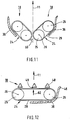
- Fig. 1 shows an example of a forage harvester for the corn crop with an agricultural machine 10 in the form of a tractor, in which a header 14 is arranged in front in the direction of travel 11 front.
- An attachment 16 according to the invention for processing the maize stubble cut off by the header 14 is attached to the header 14 in this embodiment and forms a unitary header therewith.
- the attachment 16 of the invention is the header 14 in the direction of travel 11 of the machine 10 immediately downstream and arranged in the direction of travel 11 of the machine 10 even before the front wheels 12.
- the (post) processing of the maize stubble can be done in one operation with the corn harvest through the header 14, saving time, energy and costs.
- the maize stubble can be processed in their cut, upright state, before a machine with their wheels over them drives away.
- Attachment 16 has a plurality of, in this embodiment, four plant stoppers 18 for processing plant stoppers so that four rows of maize stubble can be processed simultaneously.
- the plant stoppers 18 are mounted on a rail or strip-shaped fixture 20. With this holding device 20, they can be mounted on the header 14 or optionally also on another attachment, the machine 10 itself or a self-propelled plant stubble cultivation machine.
- the assembly of the plant stoppers 18 is preferably carried out so that they can be moved or adjusted between a working position and a non-operating position.
- the plant stoppers 18 are mounted variably adjustable in height on the holding device 20, the holding device 20 is designed variable height adjustable and / or the holding device 20 is mounted variable height adjustable.
- the attachment 16 can be adapted to the particular plant stoppers to be processed and / or the respective soil conditions.
- To comply with the desired height position above the ground are preferably sensors, feeler wheels, runners or the like guide elements 54 (see Fig. 7 ) and a device for adjusting the height of the device and / or plant stoppers on the device.
- the guide elements 54 may be attached to the fixture 20 or plant stoppers 18, for example. In the direction transverse to the working direction 11, two or more such guide elements 54 are provided on the device 16.
- the plant stoppers 18 may each be fixedly and fixedly spaced from each other on the fixture 20.
- the mutual distance or the pitch transverse to the direction of travel 11 is for example about 35 cm.
- a row-dependent attachment 16 is provided whose plant stubble cultivators are preset for certain planting ratios / row spacing.
- the plant stoppers 18 are slidably mounted on the fixture 20 so that their positions and mutual distances can be variably adjusted.
- This variant is a row-independent attachment 16, which can be easily adapted by the user to the respective planting conditions / row spacings.
- the individual plant stoppers 18 each have a suspension 22 which is attached to the fixture 20 (fixed or variable).
- the suspension 22 also includes a drive device 23 in the form of a transmission (eg gear transmission) or its own drive (eg electric motor).
- the drive devices 23 may be designed independently, be coupled together, be connected to a common drive on the attachment, on the header 14 or on the machine 10, be connected to a ground drive and the like.
- the drive devices 23 may be oriented substantially horizontally, as in FIG Fig. 2 represented, or substantially vertical.
- the individual plant stoppers 18 each have a rotary body 24, which essentially consists of a rotary element 25 in the form of a wheel, which is rotatable about a rotational axis 26 which is substantially vertical in this embodiment, driven by the respective drive device 23 in a direction of rotation 30 , and is mounted on the suspension 22.
- the circumferential surface of the wheel 25 forms a in this embodiment substantially vertically extending lateral surface 28 of the rotary body 24.
- the wheel 25 has, for example, an outer diameter of about 20 cm.
- both the axis of rotation 26 and the lateral surface 28 of the rotating body 24 are aligned at a predetermined angle of about 90 ° to the horizontal plane.
- a plate or strip-shaped counter body 36 is also attached on the suspension 22 of the plant stubble processing device 18.
- This counter-body 36 extends in the embodiment of Fig. 2 and 3 over a predetermined peripheral portion 40 in a predetermined horizontal distance 42 along the wheel 25.
- the wheel 25 side facing the counter body 36 forms a counter surface 38 which cooperates with the lateral surface 28 of the wheel 25.
- the lateral surface 28 of the rotating wheel 25 and the counter surface 38 of the counter body 36 form a gap 43 between them, into which a maize stub 44 can be received.
- the corn stub 44 in this gap 43 against the working direction 11 of the attachment 16 through the gap moved backwards while twisting about its longitudinal axis.
- the horizontal distance 42 is also smaller than the diameter of the maize stubble 44, so that the maize stubble 44 is also squeezed. This leads to a splitting / tearing / fraying and thus to an effective destruction of the maize stubble 44, which then rots faster and thus no longer provides (over) habitat for the pupae of the European corn borer.
- the maize stub 44 received in the gap 43 can also be torn out of its rootstock during the movement of the attachment 16 in the direction of travel 11 of the machine 10 or together with its rootstock or with at least parts of the rootstock out of the earth torn / pulled.
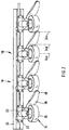
- the front edge of the counter-body 36 and its mating surface 38 in the working direction 11 is positioned in the working direction 11 of the attachment 16 behind a front plane 32 a and in front of a central diameter plane 32 b of the rotating body 24.
- the rear edge of the counter-body 36 and its mating surface 38 in the working direction 11 is positioned in the working direction 11 of the attachment 16 behind a rear plane 32c of the rotating body 24 (elongated counter-body 36a shown in phantom in FIG Fig. 3 ).
- this in the working direction rear edge of the counter body 36 may also be positioned behind the central diameter plane 32b, but even before the rear plane 32c of the rotary body 24 (solid line in Fig. 3 ).
- the counter body 36 and / or the rotary body 24 may be mounted elastically resiliently on the suspension 22 in the horizontal direction. In this case, the counter body 36 and the rotary body 24 are biased toward each other.
- maize stubble 44 can be effectively processed with different diameters and can increase the force on the corn stubble 44 and thus their destruction can be effected more effectively.
- Due to the elastically resilient mounting of the rotary body 24 and / or counter-body 36 foreign objects (eg stones, other parts of plants, etc.) which have fallen between the lateral surface 28 and counter-surface 38 can also be removed easily or even by themselves, so that the risk of a blocking plant stubble processing device 18 is reduced can be. In this context, the risk of overloading the plant stubble processing device 18 or its rotary drive (s) can be reduced.
- the corn stubble 44 is not always arranged exactly in a row on the field.
- the plant stoppers 18 also each have a guide 46 on.
- the guide devices 46 The corn stubs 44, which are offset from the plane 34b of the front gap entrance between lateral surface 28 and counter surface 38 transversely to the working direction 11, lead into this gap 43.
- the guide devices 46 are formed, for example, integrally with the counter-bodies 36 and form, for example, an extension of the counter-body 36 in the working direction 11 of the attachment 16 to the front, which merges rearwardly into the counter-body 36 and its counter-surface 38.
- the front edge of the guide 46 in the working direction 11 is positioned in the working direction 11 of the attachment 16 in front of a front plane 32 a of the rotating body 24.
- the front edge of the guide device 46 protrudes laterally beyond the plane 34c of the outer diameter of the rotational body 24 of an adjacent plant stubble cultivation device 18, for example maximally up to the diameter plane 34a of the rotational body 24 in the working direction 11.
- the lateral surface 28 of the rotary body 24 and / or the counter surface 38 of the counter body 36 optionally at least one additional device, such as a friction surface, a surface profile (such as vertical ribs or webs 50), a cutting element or a tear element have.
- a friction surface such as vertical ribs or webs 50
- a surface profile such as vertical ribs or webs 50
- a cutting element or a tear element have.
- the rotary element 25 and its additional devices are each wear elements. These are therefore preferably made of a wear-resistant or high-strength material (for example metal or plastic).
- the auxiliary devices are preferably releasably attached to the lateral surface 28 of the rotary member 25 of the rotary body 24 so that they can be easily replaced and replaced.
- the rotation member 25 of the rotating body 24 may also be formed as a ring gear, so that a weight of the plant stubble processing device can be reduced.
- this is made for example of metal.
- Fig. 4 shows a further embodiment of the invention, which is advantageous, for example, with rotational bodies 24, which are formed from rotary elements 25 with larger diameters.
- Fig. 4 are shown in the direction transverse to the direction of work 11 adjacent crop stoppers 18, but the device 16 may of course have more than these two devices 18.
- the plant stoppers 18 may each have a further extended counter body 36b.
- the extended counter body 36b can extend along the circumference of the rotary body 24 beyond the diameter plane 34a of the rotary body 24 in the working direction 11.
- Fig. 2 and 3 Another difference from the embodiment of Fig. 2 and 3 can be seen in the guide 46.
- This is designed in plan view at its front in the direction of work 11 end, for example, approximately triangular. It thus has two in the direction of 11 obliquely backward extending fins.
- the one guide surface (right in Fig. 4 ) leads as in the above embodiment of Fig. 2 and 3 a plant stub 44 in the gap 43 between the rotating body 24 and the counter body 36.
- the other guide surface (left in Fig. 4 ) directs a plant stub 44 in the direction of the rotation body 24 of (in Fig. 4 There, it is finally also conveyed into the gap 43 between the rotary body 24 and the counter body 36 by the rotating rotary body 24, or into the gap between the rotary body 24 and the further guide 48, if present (see below).
- each of the plant stoppers 18 is equipped with another guide 48.
- two or more further guide devices 48 may be provided per plant stub processing device 18.
- the guide devices 46 and the other guide devices 48 are arranged distributed regularly in the direction transverse to the working direction 11 or evenly spaced.
- the free spaces between adjacent (further) guide devices 46, 48 in the direction transverse to the working direction 11 are, for example, in a range of about 4 to 10 cm, more preferably in a range of about 5 to 8 cm.
- the distance or the spacing between adjacent (further) guide devices 46, 48 in the direction transverse to the working direction 11 is, for example, in a range of approximately 10 to 25 cm, more preferably in a range of approximately 15 to 20 cm.
- the further guide devices 48 like the front end regions of the guide devices 46, have a substantially triangular shape in plan view. They thus also have two in the direction of work 11 obliquely rearwardly extending baffles.
- the one guide surface (left in Fig. 4 ) directs a plant stub 44 into the gap 43 between the rotary body 24 and the counter body 36.
- the other guide surface (on the right in FIG Fig. 4 ) directs a plant stub 44 away from this gap 43 to the rotation body 24 of the same plant stubble processing device 18 where it is supported by the rotating body of revolution 24 in the gap 43 between the rotating body 24 and another guide 48.
- the other guide devices 48 - similar to the counter-body 36 - each have a mating surface 49, which is the lateral surface 28 of the rotating body 24 in a predetermined horizontal distance, which is dimensioned smaller than a diameter of the plant stubble 44 to be processed, positioned opposite.
- plant stubble 44 which from the guide 46 of the adjacent plant stubble processing device 18 (in Fig. 4 to the left) to the rotation body 24, and plant stoppers which are separated from the further guide 48 away from the gap 43 (in FIG Fig. 4 to the right) are guided to the rotation body 24, processed in the gap 43 between the rotating body rotation 24 and the other guide 48, ie crushed and / or twisted.
- the further guide devices 48 are also used in this embodiment as a kind of counter-body.
- the axes of rotation 26 of the rotary body 24, the lateral surfaces 28 of the rotary body 24 and / or the counter-surfaces 38 of the counter-body 36 may be employed in an angle different from 90 ° relative to the horizontal plane.
- the effectiveness of the device 16 can be improved in this way.
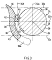
- the rotary body 24, more precisely its rotational element 25 is conical.
- the conical rotation body 24 is arranged so that its smaller diameter side obliquely downwards (toward the ground) shows.
- the peripheral speed of the rotary body 24 is higher (ie in the region of its larger diameter) than below (ie in the region of its smaller diameter.)
- a plant stub 44 in the gap 43 between the rotary body 24 and the counter-body 36 can be found in the gap 43 at the top and bottom be rotated differently, so that the plant stubble 44 can be twisted more.
- Fig. 9 The view from Fig. 9 , in which the lateral surface 28 of the conical rotational body 24 extends substantially vertically on its side facing the counter body 36, is preferably located at a location of the plant stub processing device between a front gap entrance region and the diameter plane 32b of the rotation body 24.
- the (cultivation) device 16 in addition to the above-described plant stubble cultivation devices 18, optionally have further additional devices which cause the plant stub to be torn out of the ground, the plant stubble to break off, etc.
- the device 16 is equipped, for example with a rhizome processing device 56.
- This rhizome processing device 56 serves to destroy and / or tearing out the rhizome of the plant stubble 44, if this has not already been done by the plant stubble cultivation device 18, it can therefore also be referred to as "stock clearer”.
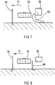
- the rhizome processing device 56 is formed, for example, as a coulter in an angle shape, goosefoot shape, etc., as a runner, as a rotatable slide plate or the like, and protrudes, for example, a predetermined depth into the ground. As in Fig. 8 illustrated, it is arranged in the working direction 11 of the device 16 behind the rotation axis 26 of the rotating body 24 of the plant stubble cultivation device 18.
- At least one rhizome processing device 56 is provided for each plant stub processing device 18, wherein it is preferably aligned in the direction transverse to the working direction 11 of the device 16 substantially at the gap 43 between the rotational body 24 and the counter body 36.
- the rootstock processing device 56 is attached to or integrated with the fixture 20, on a (height) guide, if present, or on a plant stub processing device 18.
- the plant stubble cultivation device 18 additionally has at least one clearing element 52 on its rotation body 24.
- This clearing element 52 is mounted on a side facing away from the ground of the rotating body 24 (ie above) and protrudes in the radial direction over the gap 43 between the lateral surface 28 of the rotary body 24 and the counter surface 38 of the counter body 36 away.
- the broaching element 52 is configured, for example, as a rod, strip, rake, broom, brush or the like. One, two or more such clearing elements 52 can be distributed on the rotation body 24.
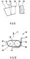
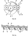
- Fig. 10 illustrates another embodiment of a plant stub processing device 18 with a variant of the above-described rotation body 24th
- the rotary body 24 has two juxtaposed rotary elements 25, each for example in the form of a (hollow) wheel.
- the two rotation elements 25 are each rotatable about a substantially vertically oriented axis of rotation 26, wherein the two rotation elements 25 are driven in the same direction of rotation 30.
- the two rotation elements 25 are preferably designed and dimensioned substantially equal.
- a jacket element 29 in the form of a band, a belt or a chain surrounds the two rotary elements 25 and thus forms the lateral surface 28 of this rotary body 24.
- the jacket element 29 is optionally equipped with the additional elements described above.
- the counterpart body 36 is connected to the greater extent of the rotational body 24 (in comparison to that in FIG Fig. 3 ) customized. Also, guide elements 46 at the front end region of the counter body 36 and preferably also further guide elements 48 (see. Fig. 4 ) be provided.
- the rotary members 25 may optionally be sized smaller (e.g., diameters in the range of about 10 to 30 cm). As a result, the rotary body 24 and thus also the entire plant stubble cultivation device 18 can be built shorter in the working direction 11.
- the rotational body 24 of the plant stubble processing device 18 of Fig. 10 has exactly two rotational elements 25, the rotational body 24 may alternatively be constructed of three, four or more juxtaposed rotation elements 25 which are encompassed by a common jacket member 29.
- FIG. 12 illustrates a specific arrangement example of at least two plant stoppers 18 in the embodiment of FIG Fig. 10 ,
- the rotation elements 25 of the rotation body 24 of a plant stubble cultivation device 18 are arranged in a direction exactly transversely to the working direction 11, ie at an angle of about 90 ° to the working direction 11, one behind the other, the rotation body 24 can be aligned in other angles of incidence 60 relative to the working direction 11.
- the preferred angles of incidence 60 of the rotary bodies 24 with respect to the working direction 11 are in a range of about 45 ° to about 90 °.
- the counter body 36 and the (possibly also further) guide elements 46, 48 are adapted accordingly in their design, dimensioning and orientation.
- the rotational body 24 can be made of adjacent crop stoppers 18 of an attachment 16 preferably alternately with respect to the working direction 11. That is, while a rotational body 24 is aligned at an angle of incidence 60 of approximately + 45 ° with respect to the working direction 11, the other rotational body 24 is aligned at an angle of incidence 60 of approximately -45 ° with respect to the working direction 11.
- Such an oblique orientation of the rotary body 24 can offer various advantages. Thus, a better or more favorable weight distribution (in particular along the working direction) can be achieved on the attachment 16 itself or on the respective agricultural machine 10.
- the oblique orientation of the rotation body 24 may allow larger rotation elements 25 and / or narrower catchment areas for plant stubble.
- By the inclination of the rotating body 24 can also the clamping distance for plant stoppers between the lateral surface 28 of the rotary body 24 and the counter surface of the counter body 36 are extended. Furthermore, the risk of obstruction of other agricultural machinery or other vehicles may also be reduced.
- the plant stub processing device 18 in a pivotable manner and / or to attach it to the holding device 20. In this way it is possible to pivot the plant stubble processing device 18 between a transport position and a working position. While the rotary body 24 of the plant stubble processing device 18 can be aligned in the transport position substantially transversely to the working direction 11, it can be pivoted in the working position, for example, obliquely forward. As a result, the center of gravity of the plant stubble cultivation device 18 is displaced further in the working direction 11 to the front.
- Fig. 12 is a further embodiment of plant stubble cultivation device 18 with a variant of the rotational body of Fig. 10 illustrated.
- the counter body 36 is adapted to the larger dimensions of the rotary body 24.
- the number of further guide elements 48 is adapted to the larger dimensions of the rotary body 24.
- the mantle element 29 in the region between the rotation elements 25 at least in the front circulation in the working direction 11 (top in FIG Fig. 12 ) to be provided from the inside with a counter-pressure 62.
- This counter-pressure 62 is intended to prevent the jacket element 29 from working in the direction of movement behind (below in Fig. 12 ) can dodge.
- the back pressure 62 may be formed, for example, by guide elements in the form of wheels, rollers, sliding surfaces, skids and the like.
- FIGS. 13 and 14 another embodiment of an attachment 16 according to the invention will be explained.
- the plant stoppers 18 each form a structural unit / module which is mounted on the (in Fig. 13 not shown) holding device 20 can be mounted.
- the individual crop stoppers 18 are in this way easier to mount on the holding device 20 and can be easily replaced if necessary.
- the rotary bodies 24 of the plant stoppers 18 are coupled together by a common gear 23, which in this example is designed as a gear transmission.
- the plant stoppers 18 of the attachment 16 may be coupled together or in groups via common gears 23.
- the (gear) transmission 23 common to all the rotary bodies 24 or a group of rotary bodies 24 may be selectively driven by one or more drive motors (e.g., electric, hydraulic).
- the rotation bodies 24 of the plant stoppers 18 are coupled to each other such that the directions of rotation 30 of the bodies of rotation 24 of adjacent crop stoppers 18 are equal to each other (synchronization).
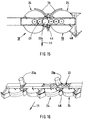
- FIGS. 15 and 16 another embodiment of an attachment 16 according to the invention will be explained.
- the plant stoppers 18 each form a structural unit / module which is attached to the (in Fig. 15 Not shown) holding device 20 can be mounted.
- the plant stoppers 18 In contrast to the embodiment of Fig. 13/14 but here contains a structural unit two plant stoppers 18 each having a rotary body 24th
- the rotational bodies 24 of the two plant stoppers 18 of a structural unit are coupled to each other via a common gear 23 in such a way that the directions of rotation 30 of the two rotational bodies 24 are opposite to each other (counter-rotation).
- the two plant stoppers 18 are driven by common (gear) transmissions 23 via a single drive motor 23a (e.g., electrically, hydraulically).
- the counter-body 36 and the guide elements 46 are arranged and configured symmetrically to each other in accordance with the mating rotation of the two rotary bodies 24, as in FIGS. 15 and 16 recognizable.
- the plant stoppers 18 of the embodiments of Fig. 13/14 or 15/16 can optionally also with rotational bodies 24 according to the embodiments of Fig. 10-12 be equipped.
Landscapes
- Life Sciences & Earth Sciences (AREA)
- Environmental Sciences (AREA)
- Engineering & Computer Science (AREA)
- Mechanical Engineering (AREA)
- Soil Sciences (AREA)
- Catching Or Destruction (AREA)
- Agricultural Machines (AREA)
Claims (16)
- Appareil agricole (16) comprenant au moins un dispositif (18) pour traiter des chaumes végétaux (44), dans lequel ce dispositif de traitement des chaumes végétaux (18) comprend :un corps rotatif (24) pouvant tourner autour d'un axe de rotation (26), dans lequel l'axe de rotation (26) du corps rotatif (24) forme un angle prédéterminé par rapport au plan horizontal ; etun contre-corps (36) comprenant une contre-surface (38) qui est positionnée en face du corps rotatif (24) à une distance horizontale prédéterminée (42),caractérisé en ce quele corps rotatif (24) comprend une surface d'enveloppe (28) périphérique ; etune distance horizontale prédéterminée (42) entre la surface d'enveloppe (28) du corps rotatif (24) et la contre-surface (38) est d'une dimension inférieure à un diamètre des chaumes végétaux (44) à traiter de telle sorte que les chaumes végétaux (44) à traiter sont reçus entre la surface d'enveloppe (28) du corps rotatif (24) en rotation et la contre-surface (38) du contre-corps (36) et sont torsadés autour de leur axe longitudinal.
- Appareil agricole selon la revendication 1,
caractérisé en ce qu'
est prévu un dispositif d'entraînement pour l'entraînement en rotation du corps rotatif (24). - Appareil agricole selon la revendication 1 ou 2,
caractérisé en ce que
le dispositif de traitement des chaumes végétaux (18) comprend un dispositif de guidage (46) qui est monté en amont du corps rotatif (24) dans une direction de travail (11) de l'appareil (16) et est configuré pour guider un chaume végétal (44) à traiter entre la surface d'enveloppe (28) du corps rotatif (24) et la contre-surface (38) du contre-corps (36). - Appareil agricole selon l'une des revendications précédentes,
caractérisé en ce que
le dispositif de traitement des chaumes végétaux (18) comprend au moins un dispositif de guidage supplémentaire (48) qui est disposé essentiellement devant le corps rotatif (24) dans une direction de travail (11) de l'appareil agricole (16) et est configuré pour guider un chaume végétal (44) à traiter dans une direction transversale à la direction de travail (11) de l'appareil (16). - Appareil agricole selon l'une des revendications précédentes,
caractérisé en ce qu'
une position dudit au moins un dispositif de traitement des chaumes végétaux (18) dans une direction transversale à la direction de travail de l'appareil (16) et/ou une distance entre deux dispositifs de traitement des chaumes végétaux (18) parmi plusieurs dispositifs de traitement des chaumes végétaux (18) dans une direction transversale à la direction de travail de l'appareil (16) peuvent être réglées de manière variable. - Appareil agricole selon l'une des revendications précédentes,
caractérisé en ce qu'
est prévu un dispositif de support (20) pour monter ledit au moins un dispositif de traitement des chaumes végétaux (18) sur une machine agricole (10) ou sur un appareil porté (14) d'une machine agricole (10), en particulier un appareil à moissonner, ou sur une machine de traitement des chaumes végétaux automotrice à une position qui est sélectionnée parmi les positions : devant une roue avant dans la direction de travail (11) de la machine, derrière une roue arrière dans la direction de travail (11) de la machine, entre les roues de la machine dans la direction de travail (11) de la machine, devant / derrière la machine dans la direction de travail (11) de la machine, sur un côté de la machine dans la direction de travail (11) de la machine, et parmi des combinaisons de ces positions. - Appareil agricole selon la revendication 6,
caractérisé en ce que
le dispositif de support (20) peut être monté de manière ajustable, en particulier ajustable en hauteur, sur la machine agricole (10), l'appareil porté (14) ou la machine de traitement des chaumes végétaux automotrice, et/ou ledit au moins un dispositif de traitement des chaumes végétaux (18) est monté de manière ajustable, en particulier ajustable en hauteur, sur le dispositif de support (20). - Appareil agricole selon la revendication 6 ou 7,
caractérisé en ce que
les dispositifs de traitement des chaumes végétaux (18) en tant qu'unités modulaires peuvent être fixés au dispositif de support (20), dans lequel chaque unité modulaire comprend un, deux ou plus de deux dispositifs de traitement des chaumes végétaux (18) comprenant un dispositif d'entraînement (23) commun. - Appareil agricole selon l'une des revendications précédentes,
caractérisé en ce que
la surface d'enveloppe (28) du corps rotatif (24) et/ou la contre-surface (38) du contre-corps (36) comprennent au moins un dispositif supplémentaire qui est sélectionné parmi des surfaces de frottement, des profils de surface (50), des éléments de coupe et des éléments de déchirement. - Appareil agricole selon l'une des revendications précédentes,
caractérisé en ce que
le contre-corps (36) et/ou le corps rotatif (24) sont montés de manière élastique dans la direction horizontale et sont précontraints dans la direction des autres composants respectifs du contre-corps (36) et du corps rotatif (24). - Appareil agricole selon l'une des revendications précédentes,
caractérisé en ce qu'
un espace (43) entre la surface d'enveloppe (28) du corps rotatif (24) et la contre-surface (38) du contre-corps (36) s'élargit vers le bas. - Appareil agricole selon l'une des revendications précédentes,
caractérisé en ce que
le corps rotatif (24) du dispositif de traitement des chaumes végétaux (18) comprend au moins deux éléments rotatifs (25) qui sont disposés l'un à côté de l'autre et ont un même sens de rotation, et un élément d'enveloppe (29) entourant lesdits au moins deux éléments rotatifs (25) afin de former la surface d'enveloppe (28) du corps rotatif. - Machine agricole (10) comprenant un appareil porté configuré comme un appareil agricole (16) selon l'une des revendications 1 à 12.
- Machine agricole (10) comprenant un appareil à moissonner (14) et un appareil porté configuré comme un appareil agricole (16) selon l'une des revendications 1 à 12.
- Machine de traitement des chaumes végétaux automotrice comprenant un appareil agricole (16) selon l'une des revendications 1 à 12.
- Procédé de traitement des chaumes végétaux (44) sur un champ, dans lequel les chaumes végétaux (44) sont reçus entre une surface d'enveloppe (28) d'un corps rotatif (24) en rotation, lequel a un axe de rotation (26) qui forme un angle prédéterminé par rapport au plan horizontal du champ, et une contre-surface (38) d'un contre-corps (36), et sont torsadés autour de leur axe longitudinal et/ou pressés.
Priority Applications (1)
| Application Number | Priority Date | Filing Date | Title |
|---|---|---|---|
| PL14732573T PL3016494T3 (pl) | 2013-07-05 | 2014-06-25 | Sprzęt rolniczy i sposób obróbki ścierni |
Applications Claiming Priority (3)
| Application Number | Priority Date | Filing Date | Title |
|---|---|---|---|
| DE102013011272.9A DE102013011272A1 (de) | 2013-07-05 | 2013-07-05 | Landwirtschaftliches Gerät und Verfahren zur Bearbeitung von Pflanzenstoppeln |
| DE202013105582.4U DE202013105582U1 (de) | 2013-07-05 | 2013-12-09 | Landwirtschaftliches Gerät |
| PCT/EP2014/063429 WO2015000768A1 (fr) | 2013-07-05 | 2014-06-25 | Appareil agricole et procédé de traitement de chaumes végétaux |
Publications (2)
| Publication Number | Publication Date |
|---|---|
| EP3016494A1 EP3016494A1 (fr) | 2016-05-11 |
| EP3016494B1 true EP3016494B1 (fr) | 2019-05-22 |
Family
ID=51787831
Family Applications (1)
| Application Number | Title | Priority Date | Filing Date |
|---|---|---|---|
| EP14732573.2A Active EP3016494B1 (fr) | 2013-07-05 | 2014-06-25 | Appareil agricole et procédé de traitement de chaumes végétaux |
Country Status (5)
| Country | Link |
|---|---|
| EP (1) | EP3016494B1 (fr) |
| DE (2) | DE102013011272A1 (fr) |
| HU (1) | HUE044190T2 (fr) |
| PL (1) | PL3016494T3 (fr) |
| WO (1) | WO2015000768A1 (fr) |
Cited By (1)
| Publication number | Priority date | Publication date | Assignee | Title |
|---|---|---|---|---|
| EP4555851A1 (fr) * | 2023-11-20 | 2025-05-21 | Nardi Srl | Appareil pour la récolte sur le terrain de tournesols |
Families Citing this family (7)
| Publication number | Priority date | Publication date | Assignee | Title |
|---|---|---|---|---|
| DE102015004212A1 (de) | 2015-03-31 | 2016-10-06 | Ingo Koscielny | Walzeneinheit für ein landwirtschaftliches Arbeitsgerät zur Maisstoppelbearbeitung |
| DE102015115554B4 (de) * | 2015-09-15 | 2025-04-30 | Sima Investment Ag | Vorrichtung zum Zerkleinern und/oder Zerquetschen von Ernterückständen von Reihenkulturen |
| DE102016214324A1 (de) | 2016-08-03 | 2018-02-08 | Deere & Company | Erntevorsatz mit einem Mulchgerät zur Bearbeitung von auf einem Feld stehenden Pflanzenstümpfen |
| DE102016214317A1 (de) | 2016-08-03 | 2018-02-08 | Deere & Company | Mulchgerät zur Bearbeitung von auf einem Feld stehenden Pflanzenstümpfen |
| US10945371B2 (en) | 2018-06-05 | 2021-03-16 | Cnh Industrial America Llc | Adjustable stalk stomper/chopper curtain assembly |
| CN113016245A (zh) * | 2021-03-29 | 2021-06-25 | 安徽农业大学 | 一种便于玉米秸秆还田用多功能旋耕机 |
| CN117796189B (zh) * | 2024-02-01 | 2025-11-21 | 中国科学院遗传与发育生物学研究所农业资源研究中心 | 一种基于静态地膜的拔耕播种机 |
Family Cites Families (8)
| Publication number | Priority date | Publication date | Assignee | Title |
|---|---|---|---|---|
| DE2011976A1 (de) * | 1970-03-13 | 1971-09-23 | Maschinenfabrik Fahr Ag, 7702 Gottmadingen | Erntemaschine für in Reihe stehende Halmfrüchte, insbesondere Mais |
| DE3727535C2 (de) * | 1986-11-07 | 1996-02-08 | Biso Maschf Gmbh | Pflückvorrichtung zum Ernten von Halmfrüchten, insbesondere Mais |
| DE9301465U1 (de) | 1993-02-03 | 1993-05-27 | Wolfensberger Ag Kartonagen + Verpackungsdruck, Zumikon | Träger zum Ausbringen von Eiern |
| DE102004020447B4 (de) | 2004-04-27 | 2006-07-13 | Maschinenfabrik Bernard Krone Gmbh | Selbstfahrende Erntemaschine |
| DE102007043326A1 (de) | 2007-09-12 | 2009-03-19 | Claas Saulgau Gmbh | Verfahren und Vorrichtung zur Bekämpfung einer Verbreitung von fressenden Pflanzenschädlingen |
| DE202009016468U1 (de) | 2009-12-10 | 2010-03-04 | Niebuhr, Willi | Selbstfahrende landwirtschaftliche Maschine |
| DE102010012686A1 (de) | 2010-03-24 | 2011-09-29 | Müthing GmbH & Co. KG | Vorrichtung zum Aufrichten von Halmgut |
| DE202011003182U1 (de) | 2011-02-24 | 2011-05-19 | Römischer, Gustav, Dipl.-Ing. (FH), 86356 | Bodenbearbeitungsmaschine |
-
2013
- 2013-07-05 DE DE102013011272.9A patent/DE102013011272A1/de not_active Withdrawn
- 2013-12-09 DE DE202013105582.4U patent/DE202013105582U1/de not_active Expired - Lifetime
-
2014
- 2014-06-25 PL PL14732573T patent/PL3016494T3/pl unknown
- 2014-06-25 WO PCT/EP2014/063429 patent/WO2015000768A1/fr not_active Ceased
- 2014-06-25 EP EP14732573.2A patent/EP3016494B1/fr active Active
- 2014-06-25 HU HUE14732573 patent/HUE044190T2/hu unknown
Non-Patent Citations (1)
| Title |
|---|
| None * |
Cited By (1)
| Publication number | Priority date | Publication date | Assignee | Title |
|---|---|---|---|---|
| EP4555851A1 (fr) * | 2023-11-20 | 2025-05-21 | Nardi Srl | Appareil pour la récolte sur le terrain de tournesols |
Also Published As
| Publication number | Publication date |
|---|---|
| HUE044190T2 (hu) | 2019-10-28 |
| WO2015000768A1 (fr) | 2015-01-08 |
| PL3016494T3 (pl) | 2019-10-31 |
| DE202013105582U1 (de) | 2014-10-06 |
| EP3016494A1 (fr) | 2016-05-11 |
| DE102013011272A1 (de) | 2015-01-08 |
Similar Documents
| Publication | Publication Date | Title |
|---|---|---|
| EP3016494B1 (fr) | Appareil agricole et procédé de traitement de chaumes végétaux | |
| EP0091635B2 (fr) | Méthode et appareil pour récolter le mais ou autres céréales | |
| EP3272199B1 (fr) | Broyeur destiné au traitement de résidus de cultures dans un champ | |
| EP2656724B1 (fr) | Machine destinée à la récolte de plantes à tiges dotée d'un corps de battage disposé au-dessous d'un disque de coupe pour défibrer les chaumes | |
| EP2255610B1 (fr) | Tête pour récolter des plantes en forme de tige | |
| EP3199010B1 (fr) | Gyrobroyeur de chaume | |
| EP3387890A1 (fr) | Unité de travail sur la ligne destinée au désherbage mécanique, engin agricole pourvu d'au moins deux unités de travail sur la ligne ainsi que procédé de désherbage mécanique | |
| EP3346820A1 (fr) | Dispositif de récolte de produits à tige sur pied | |
| EP3001892B1 (fr) | Appareil de moissonnage de maïs comprenant un dechaumeur et hache-pailles | |
| DE1457690A1 (de) | Garten- und Ackerbaugeraet | |
| EP3354126A1 (fr) | Couteau et tambour de hachoir pour une ramasseuse-hacheuse | |
| EP1566092B1 (fr) | Dispositif de récolte avec broyeur | |
| EP2661949A1 (fr) | Dispositif de découpage destiné au traitement mécanique de résidus de récoltes pour empêcher la propagation de nuisibles sur les plantes et les attaques fongiques | |
| EP2792232A1 (fr) | Broyeur et dispositif de ramassage pour materiél à couper | |
| DE102016214323A1 (de) | Mulcheinrichtung zur mechanischen Bearbeitung von Pflanzenstoppeln | |
| DE2302980A1 (de) | Geraetetraeger fuer rotierende landwirtschaftliche arbeitsgeraete | |
| DE102015004212A1 (de) | Walzeneinheit für ein landwirtschaftliches Arbeitsgerät zur Maisstoppelbearbeitung | |
| DE102005049716B4 (de) | Mähhacker für Pflanzen | |
| EP3881665A1 (fr) | Appareil de paillage destiné au traitement des chaumes végétaux | |
| DE102016214324A1 (de) | Erntevorsatz mit einem Mulchgerät zur Bearbeitung von auf einem Feld stehenden Pflanzenstümpfen | |
| DE10350302B4 (de) | Pflückvorsatz für ein Erntegerät | |
| DE102016208511B4 (de) | Maschine zur Ernte stängelartiger Pflanzen mit einer Schneidenanordnung zum Zerkleinern der Stoppeln | |
| DE102005055621B3 (de) | Maschine zur Ernte stängelartiger Pflanzen | |
| EP2882274B1 (fr) | Dispositif pour entailler une couche de matière organique couchée sur la surface du sol, et utilisation de ce dispositif | |
| DE202015106946U1 (de) | Bodenbearbeitungsvorrichtung |
Legal Events
| Date | Code | Title | Description |
|---|---|---|---|
| PUAI | Public reference made under article 153(3) epc to a published international application that has entered the european phase |
Free format text: ORIGINAL CODE: 0009012 |
|
| 17P | Request for examination filed |
Effective date: 20160113 |
|
| AK | Designated contracting states |
Kind code of ref document: A1 Designated state(s): AL AT BE BG CH CY CZ DE DK EE ES FI FR GB GR HR HU IE IS IT LI LT LU LV MC MK MT NL NO PL PT RO RS SE SI SK SM TR |
|
| AX | Request for extension of the european patent |
Extension state: BA ME |
|
| DAX | Request for extension of the european patent (deleted) | ||
| GRAP | Despatch of communication of intention to grant a patent |
Free format text: ORIGINAL CODE: EPIDOSNIGR1 |
|
| STAA | Information on the status of an ep patent application or granted ep patent |
Free format text: STATUS: GRANT OF PATENT IS INTENDED |
|
| INTG | Intention to grant announced |
Effective date: 20181218 |
|
| GRAS | Grant fee paid |
Free format text: ORIGINAL CODE: EPIDOSNIGR3 |
|
| GRAA | (expected) grant |
Free format text: ORIGINAL CODE: 0009210 |
|
| STAA | Information on the status of an ep patent application or granted ep patent |
Free format text: STATUS: THE PATENT HAS BEEN GRANTED |
|
| AK | Designated contracting states |
Kind code of ref document: B1 Designated state(s): AL AT BE BG CH CY CZ DE DK EE ES FI FR GB GR HR HU IE IS IT LI LT LU LV MC MK MT NL NO PL PT RO RS SE SI SK SM TR |
|
| REG | Reference to a national code |
Ref country code: GB Ref legal event code: FG4D Free format text: NOT ENGLISH |
|
| REG | Reference to a national code |
Ref country code: CH Ref legal event code: EP |
|
| REG | Reference to a national code |
Ref country code: IE Ref legal event code: FG4D Free format text: LANGUAGE OF EP DOCUMENT: GERMAN |
|
| REG | Reference to a national code |
Ref country code: DE Ref legal event code: R096 Ref document number: 502014011769 Country of ref document: DE |
|
| REG | Reference to a national code |
Ref country code: AT Ref legal event code: REF Ref document number: 1134937 Country of ref document: AT Kind code of ref document: T Effective date: 20190615 |
|
| REG | Reference to a national code |
Ref country code: NL Ref legal event code: MP Effective date: 20190522 |
|
| REG | Reference to a national code |
Ref country code: LT Ref legal event code: MG4D |
|
| REG | Reference to a national code |
Ref country code: HU Ref legal event code: AG4A Ref document number: E044190 Country of ref document: HU |
|
| PG25 | Lapsed in a contracting state [announced via postgrant information from national office to epo] |
Ref country code: PT Free format text: LAPSE BECAUSE OF FAILURE TO SUBMIT A TRANSLATION OF THE DESCRIPTION OR TO PAY THE FEE WITHIN THE PRESCRIBED TIME-LIMIT Effective date: 20190922 Ref country code: AL Free format text: LAPSE BECAUSE OF FAILURE TO SUBMIT A TRANSLATION OF THE DESCRIPTION OR TO PAY THE FEE WITHIN THE PRESCRIBED TIME-LIMIT Effective date: 20190522 Ref country code: SE Free format text: LAPSE BECAUSE OF FAILURE TO SUBMIT A TRANSLATION OF THE DESCRIPTION OR TO PAY THE FEE WITHIN THE PRESCRIBED TIME-LIMIT Effective date: 20190522 Ref country code: FI Free format text: LAPSE BECAUSE OF FAILURE TO SUBMIT A TRANSLATION OF THE DESCRIPTION OR TO PAY THE FEE WITHIN THE PRESCRIBED TIME-LIMIT Effective date: 20190522 Ref country code: NO Free format text: LAPSE BECAUSE OF FAILURE TO SUBMIT A TRANSLATION OF THE DESCRIPTION OR TO PAY THE FEE WITHIN THE PRESCRIBED TIME-LIMIT Effective date: 20190822 Ref country code: HR Free format text: LAPSE BECAUSE OF FAILURE TO SUBMIT A TRANSLATION OF THE DESCRIPTION OR TO PAY THE FEE WITHIN THE PRESCRIBED TIME-LIMIT Effective date: 20190522 Ref country code: NL Free format text: LAPSE BECAUSE OF FAILURE TO SUBMIT A TRANSLATION OF THE DESCRIPTION OR TO PAY THE FEE WITHIN THE PRESCRIBED TIME-LIMIT Effective date: 20190522 Ref country code: ES Free format text: LAPSE BECAUSE OF FAILURE TO SUBMIT A TRANSLATION OF THE DESCRIPTION OR TO PAY THE FEE WITHIN THE PRESCRIBED TIME-LIMIT Effective date: 20190522 Ref country code: LT Free format text: LAPSE BECAUSE OF FAILURE TO SUBMIT A TRANSLATION OF THE DESCRIPTION OR TO PAY THE FEE WITHIN THE PRESCRIBED TIME-LIMIT Effective date: 20190522 |
|
| PG25 | Lapsed in a contracting state [announced via postgrant information from national office to epo] |
Ref country code: RS Free format text: LAPSE BECAUSE OF FAILURE TO SUBMIT A TRANSLATION OF THE DESCRIPTION OR TO PAY THE FEE WITHIN THE PRESCRIBED TIME-LIMIT Effective date: 20190522 Ref country code: BG Free format text: LAPSE BECAUSE OF FAILURE TO SUBMIT A TRANSLATION OF THE DESCRIPTION OR TO PAY THE FEE WITHIN THE PRESCRIBED TIME-LIMIT Effective date: 20190822 Ref country code: GR Free format text: LAPSE BECAUSE OF FAILURE TO SUBMIT A TRANSLATION OF THE DESCRIPTION OR TO PAY THE FEE WITHIN THE PRESCRIBED TIME-LIMIT Effective date: 20190823 Ref country code: LV Free format text: LAPSE BECAUSE OF FAILURE TO SUBMIT A TRANSLATION OF THE DESCRIPTION OR TO PAY THE FEE WITHIN THE PRESCRIBED TIME-LIMIT Effective date: 20190522 |
|
| PG25 | Lapsed in a contracting state [announced via postgrant information from national office to epo] |
Ref country code: DK Free format text: LAPSE BECAUSE OF FAILURE TO SUBMIT A TRANSLATION OF THE DESCRIPTION OR TO PAY THE FEE WITHIN THE PRESCRIBED TIME-LIMIT Effective date: 20190522 Ref country code: EE Free format text: LAPSE BECAUSE OF FAILURE TO SUBMIT A TRANSLATION OF THE DESCRIPTION OR TO PAY THE FEE WITHIN THE PRESCRIBED TIME-LIMIT Effective date: 20190522 Ref country code: SK Free format text: LAPSE BECAUSE OF FAILURE TO SUBMIT A TRANSLATION OF THE DESCRIPTION OR TO PAY THE FEE WITHIN THE PRESCRIBED TIME-LIMIT Effective date: 20190522 Ref country code: RO Free format text: LAPSE BECAUSE OF FAILURE TO SUBMIT A TRANSLATION OF THE DESCRIPTION OR TO PAY THE FEE WITHIN THE PRESCRIBED TIME-LIMIT Effective date: 20190522 Ref country code: CZ Free format text: LAPSE BECAUSE OF FAILURE TO SUBMIT A TRANSLATION OF THE DESCRIPTION OR TO PAY THE FEE WITHIN THE PRESCRIBED TIME-LIMIT Effective date: 20190522 |
|
| REG | Reference to a national code |
Ref country code: CH Ref legal event code: PL |
|
| REG | Reference to a national code |
Ref country code: DE Ref legal event code: R097 Ref document number: 502014011769 Country of ref document: DE |
|
| PG25 | Lapsed in a contracting state [announced via postgrant information from national office to epo] |
Ref country code: MC Free format text: LAPSE BECAUSE OF FAILURE TO SUBMIT A TRANSLATION OF THE DESCRIPTION OR TO PAY THE FEE WITHIN THE PRESCRIBED TIME-LIMIT Effective date: 20190522 Ref country code: SM Free format text: LAPSE BECAUSE OF FAILURE TO SUBMIT A TRANSLATION OF THE DESCRIPTION OR TO PAY THE FEE WITHIN THE PRESCRIBED TIME-LIMIT Effective date: 20190522 |
|
| PLBE | No opposition filed within time limit |
Free format text: ORIGINAL CODE: 0009261 |
|
| REG | Reference to a national code |
Ref country code: BE Ref legal event code: MM Effective date: 20190630 |
|
| STAA | Information on the status of an ep patent application or granted ep patent |
Free format text: STATUS: NO OPPOSITION FILED WITHIN TIME LIMIT |
|
| PG25 | Lapsed in a contracting state [announced via postgrant information from national office to epo] |
Ref country code: TR Free format text: LAPSE BECAUSE OF FAILURE TO SUBMIT A TRANSLATION OF THE DESCRIPTION OR TO PAY THE FEE WITHIN THE PRESCRIBED TIME-LIMIT Effective date: 20190522 |
|
| 26N | No opposition filed |
Effective date: 20200225 |
|
| GBPC | Gb: european patent ceased through non-payment of renewal fee |
Effective date: 20190822 |
|
| PG25 | Lapsed in a contracting state [announced via postgrant information from national office to epo] |
Ref country code: IE Free format text: LAPSE BECAUSE OF NON-PAYMENT OF DUE FEES Effective date: 20190625 |
|
| PG25 | Lapsed in a contracting state [announced via postgrant information from national office to epo] |
Ref country code: LI Free format text: LAPSE BECAUSE OF NON-PAYMENT OF DUE FEES Effective date: 20190630 Ref country code: SI Free format text: LAPSE BECAUSE OF FAILURE TO SUBMIT A TRANSLATION OF THE DESCRIPTION OR TO PAY THE FEE WITHIN THE PRESCRIBED TIME-LIMIT Effective date: 20190522 Ref country code: LU Free format text: LAPSE BECAUSE OF NON-PAYMENT OF DUE FEES Effective date: 20190625 Ref country code: CH Free format text: LAPSE BECAUSE OF NON-PAYMENT OF DUE FEES Effective date: 20190630 Ref country code: BE Free format text: LAPSE BECAUSE OF NON-PAYMENT OF DUE FEES Effective date: 20190630 |
|
| PG25 | Lapsed in a contracting state [announced via postgrant information from national office to epo] |
Ref country code: GB Free format text: LAPSE BECAUSE OF NON-PAYMENT OF DUE FEES Effective date: 20190822 |
|
| PG25 | Lapsed in a contracting state [announced via postgrant information from national office to epo] |
Ref country code: CY Free format text: LAPSE BECAUSE OF FAILURE TO SUBMIT A TRANSLATION OF THE DESCRIPTION OR TO PAY THE FEE WITHIN THE PRESCRIBED TIME-LIMIT Effective date: 20190522 |
|
| PG25 | Lapsed in a contracting state [announced via postgrant information from national office to epo] |
Ref country code: IS Free format text: LAPSE BECAUSE OF FAILURE TO SUBMIT A TRANSLATION OF THE DESCRIPTION OR TO PAY THE FEE WITHIN THE PRESCRIBED TIME-LIMIT Effective date: 20190922 |
|
| PG25 | Lapsed in a contracting state [announced via postgrant information from national office to epo] |
Ref country code: MT Free format text: LAPSE BECAUSE OF FAILURE TO SUBMIT A TRANSLATION OF THE DESCRIPTION OR TO PAY THE FEE WITHIN THE PRESCRIBED TIME-LIMIT Effective date: 20190522 |
|
| PG25 | Lapsed in a contracting state [announced via postgrant information from national office to epo] |
Ref country code: MK Free format text: LAPSE BECAUSE OF FAILURE TO SUBMIT A TRANSLATION OF THE DESCRIPTION OR TO PAY THE FEE WITHIN THE PRESCRIBED TIME-LIMIT Effective date: 20190522 |
|
| PGFP | Annual fee paid to national office [announced via postgrant information from national office to epo] |
Ref country code: FR Payment date: 20230630 Year of fee payment: 10 |
|
| PGFP | Annual fee paid to national office [announced via postgrant information from national office to epo] |
Ref country code: PL Payment date: 20230609 Year of fee payment: 10 Ref country code: HU Payment date: 20230619 Year of fee payment: 10 Ref country code: AT Payment date: 20230622 Year of fee payment: 10 |
|
| PGFP | Annual fee paid to national office [announced via postgrant information from national office to epo] |
Ref country code: IT Payment date: 20230627 Year of fee payment: 10 |
|
| REG | Reference to a national code |
Ref country code: AT Ref legal event code: MM01 Ref document number: 1134937 Country of ref document: AT Kind code of ref document: T Effective date: 20240625 |
|
| PG25 | Lapsed in a contracting state [announced via postgrant information from national office to epo] |
Ref country code: HU Free format text: LAPSE BECAUSE OF NON-PAYMENT OF DUE FEES Effective date: 20240626 |
|
| PG25 | Lapsed in a contracting state [announced via postgrant information from national office to epo] |
Ref country code: HU Free format text: LAPSE BECAUSE OF NON-PAYMENT OF DUE FEES Effective date: 20240626 |
|
| REG | Reference to a national code |
Ref country code: DE Ref legal event code: R084 Ref document number: 502014011769 Country of ref document: DE |
|
| PG25 | Lapsed in a contracting state [announced via postgrant information from national office to epo] |
Ref country code: AT Free format text: LAPSE BECAUSE OF NON-PAYMENT OF DUE FEES Effective date: 20240625 |
|
| PG25 | Lapsed in a contracting state [announced via postgrant information from national office to epo] |
Ref country code: FR Free format text: LAPSE BECAUSE OF NON-PAYMENT OF DUE FEES Effective date: 20240630 |
|
| PG25 | Lapsed in a contracting state [announced via postgrant information from national office to epo] |
Ref country code: IT Free format text: LAPSE BECAUSE OF NON-PAYMENT OF DUE FEES Effective date: 20240625 |
|
| PGFP | Annual fee paid to national office [announced via postgrant information from national office to epo] |
Ref country code: DE Payment date: 20250515 Year of fee payment: 12 |
|
| PG25 | Lapsed in a contracting state [announced via postgrant information from national office to epo] |
Ref country code: PL Free format text: LAPSE BECAUSE OF NON-PAYMENT OF DUE FEES Effective date: 20240625 |
|
| REG | Reference to a national code |
Ref country code: DE Ref legal event code: R082 Ref document number: 502014011769 Country of ref document: DE Representative=s name: GULDE & PARTNER PATENT- UND RECHTSANWALTSKANZL, DE |