EP3016754B1 - Installation et procédé pour laminer à chaud des feuillards d'acier - Google Patents
Installation et procédé pour laminer à chaud des feuillards d'acier Download PDFInfo
- Publication number
- EP3016754B1 EP3016754B1 EP14736716.3A EP14736716A EP3016754B1 EP 3016754 B1 EP3016754 B1 EP 3016754B1 EP 14736716 A EP14736716 A EP 14736716A EP 3016754 B1 EP3016754 B1 EP 3016754B1
- Authority
- EP
- European Patent Office
- Prior art keywords
- rolling
- cooling
- steel strip
- hot
- stand
- Prior art date
- Legal status (The legal status is an assumption and is not a legal conclusion. Google has not performed a legal analysis and makes no representation as to the accuracy of the status listed.)
- Active
Links
Images


Classifications
-
- B—PERFORMING OPERATIONS; TRANSPORTING
- B21—MECHANICAL METAL-WORKING WITHOUT ESSENTIALLY REMOVING MATERIAL; PUNCHING METAL
- B21B—ROLLING OF METAL
- B21B1/00—Metal-rolling methods or mills for making semi-finished products of solid or profiled cross-section; Sequence of operations in milling trains; Layout of rolling-mill plant, e.g. grouping of stands; Succession of passes or of sectional pass alternations
- B21B1/22—Metal-rolling methods or mills for making semi-finished products of solid or profiled cross-section; Sequence of operations in milling trains; Layout of rolling-mill plant, e.g. grouping of stands; Succession of passes or of sectional pass alternations for rolling plates, strips, bands or sheets of indefinite length
-
- B—PERFORMING OPERATIONS; TRANSPORTING
- B21—MECHANICAL METAL-WORKING WITHOUT ESSENTIALLY REMOVING MATERIAL; PUNCHING METAL
- B21B—ROLLING OF METAL
- B21B37/00—Control devices or methods specially adapted for metal-rolling mills or the work produced thereby
- B21B37/74—Temperature control, e.g. by cooling or heating the rolls or the product
-
- B—PERFORMING OPERATIONS; TRANSPORTING
- B21—MECHANICAL METAL-WORKING WITHOUT ESSENTIALLY REMOVING MATERIAL; PUNCHING METAL
- B21B—ROLLING OF METAL
- B21B45/00—Devices for surface or other treatment of work, specially combined with or arranged in, or specially adapted for use in connection with, metal-rolling mills
- B21B45/02—Devices for surface or other treatment of work, specially combined with or arranged in, or specially adapted for use in connection with, metal-rolling mills for lubricating, cooling, or cleaning
- B21B45/0203—Cooling
- B21B45/0209—Cooling devices, e.g. using gaseous coolants
- B21B45/0215—Cooling devices, e.g. using gaseous coolants using liquid coolants, e.g. for sections, for tubes
- B21B45/0218—Cooling devices, e.g. using gaseous coolants using liquid coolants, e.g. for sections, for tubes for strips, sheets, or plates
-
- C—CHEMISTRY; METALLURGY
- C21—METALLURGY OF IRON
- C21D—MODIFYING THE PHYSICAL STRUCTURE OF FERROUS METALS; GENERAL DEVICES FOR HEAT TREATMENT OF FERROUS OR NON-FERROUS METALS OR ALLOYS; MAKING METAL MALLEABLE, e.g. BY DECARBURISATION OR TEMPERING
- C21D8/00—Modifying the physical properties of ferrous metals or ferrous alloys by deformation combined with, or followed by, heat treatment
- C21D8/02—Modifying the physical properties of ferrous metals or ferrous alloys by deformation combined with, or followed by, heat treatment during manufacturing of plates or strips
- C21D8/0221—Modifying the physical properties of ferrous metals or ferrous alloys by deformation combined with, or followed by, heat treatment during manufacturing of plates or strips characterised by the working steps
- C21D8/0226—Hot rolling
-
- C—CHEMISTRY; METALLURGY
- C21—METALLURGY OF IRON
- C21D—MODIFYING THE PHYSICAL STRUCTURE OF FERROUS METALS; GENERAL DEVICES FOR HEAT TREATMENT OF FERROUS OR NON-FERROUS METALS OR ALLOYS; MAKING METAL MALLEABLE, e.g. BY DECARBURISATION OR TEMPERING
- C21D8/00—Modifying the physical properties of ferrous metals or ferrous alloys by deformation combined with, or followed by, heat treatment
- C21D8/02—Modifying the physical properties of ferrous metals or ferrous alloys by deformation combined with, or followed by, heat treatment during manufacturing of plates or strips
- C21D8/0247—Modifying the physical properties of ferrous metals or ferrous alloys by deformation combined with, or followed by, heat treatment during manufacturing of plates or strips characterised by the heat treatment
- C21D8/0263—Modifying the physical properties of ferrous metals or ferrous alloys by deformation combined with, or followed by, heat treatment during manufacturing of plates or strips characterised by the heat treatment following hot rolling
-
- C—CHEMISTRY; METALLURGY
- C21—METALLURGY OF IRON
- C21D—MODIFYING THE PHYSICAL STRUCTURE OF FERROUS METALS; GENERAL DEVICES FOR HEAT TREATMENT OF FERROUS OR NON-FERROUS METALS OR ALLOYS; MAKING METAL MALLEABLE, e.g. BY DECARBURISATION OR TEMPERING
- C21D9/00—Heat treatment, e.g. annealing, hardening, quenching or tempering, adapted for particular articles; Furnaces therefor
- C21D9/52—Heat treatment, e.g. annealing, hardening, quenching or tempering, adapted for particular articles; Furnaces therefor for wires; for strips ; for rods of unlimited length
- C21D9/54—Furnaces for treating strips or wire
- C21D9/56—Continuous furnaces for strip or wire
- C21D9/573—Continuous furnaces for strip or wire with cooling
-
- F—MECHANICAL ENGINEERING; LIGHTING; HEATING; WEAPONS; BLASTING
- F27—FURNACES; KILNS; OVENS; RETORTS
- F27D—DETAILS OR ACCESSORIES OF FURNACES, KILNS, OVENS OR RETORTS, IN SO FAR AS THEY ARE OF KINDS OCCURRING IN MORE THAN ONE KIND OF FURNACE
- F27D15/00—Handling or treating discharged material; Supports or receiving chambers therefor
- F27D15/02—Cooling
- F27D15/0206—Cooling with means to convey the charge
-
- B—PERFORMING OPERATIONS; TRANSPORTING
- B21—MECHANICAL METAL-WORKING WITHOUT ESSENTIALLY REMOVING MATERIAL; PUNCHING METAL
- B21B—ROLLING OF METAL
- B21B1/00—Metal-rolling methods or mills for making semi-finished products of solid or profiled cross-section; Sequence of operations in milling trains; Layout of rolling-mill plant, e.g. grouping of stands; Succession of passes or of sectional pass alternations
- B21B1/22—Metal-rolling methods or mills for making semi-finished products of solid or profiled cross-section; Sequence of operations in milling trains; Layout of rolling-mill plant, e.g. grouping of stands; Succession of passes or of sectional pass alternations for rolling plates, strips, bands or sheets of indefinite length
- B21B1/24—Metal-rolling methods or mills for making semi-finished products of solid or profiled cross-section; Sequence of operations in milling trains; Layout of rolling-mill plant, e.g. grouping of stands; Succession of passes or of sectional pass alternations for rolling plates, strips, bands or sheets of indefinite length in a continuous or semi-continuous process
- B21B1/26—Metal-rolling methods or mills for making semi-finished products of solid or profiled cross-section; Sequence of operations in milling trains; Layout of rolling-mill plant, e.g. grouping of stands; Succession of passes or of sectional pass alternations for rolling plates, strips, bands or sheets of indefinite length in a continuous or semi-continuous process by hot-rolling, e.g. Steckel hot mill
-
- B—PERFORMING OPERATIONS; TRANSPORTING
- B21—MECHANICAL METAL-WORKING WITHOUT ESSENTIALLY REMOVING MATERIAL; PUNCHING METAL
- B21B—ROLLING OF METAL
- B21B1/00—Metal-rolling methods or mills for making semi-finished products of solid or profiled cross-section; Sequence of operations in milling trains; Layout of rolling-mill plant, e.g. grouping of stands; Succession of passes or of sectional pass alternations
- B21B1/22—Metal-rolling methods or mills for making semi-finished products of solid or profiled cross-section; Sequence of operations in milling trains; Layout of rolling-mill plant, e.g. grouping of stands; Succession of passes or of sectional pass alternations for rolling plates, strips, bands or sheets of indefinite length
- B21B2001/225—Metal-rolling methods or mills for making semi-finished products of solid or profiled cross-section; Sequence of operations in milling trains; Layout of rolling-mill plant, e.g. grouping of stands; Succession of passes or of sectional pass alternations for rolling plates, strips, bands or sheets of indefinite length by hot-rolling
-
- C—CHEMISTRY; METALLURGY
- C21—METALLURGY OF IRON
- C21D—MODIFYING THE PHYSICAL STRUCTURE OF FERROUS METALS; GENERAL DEVICES FOR HEAT TREATMENT OF FERROUS OR NON-FERROUS METALS OR ALLOYS; MAKING METAL MALLEABLE, e.g. BY DECARBURISATION OR TEMPERING
- C21D8/00—Modifying the physical properties of ferrous metals or ferrous alloys by deformation combined with, or followed by, heat treatment
- C21D8/02—Modifying the physical properties of ferrous metals or ferrous alloys by deformation combined with, or followed by, heat treatment during manufacturing of plates or strips
- C21D8/0221—Modifying the physical properties of ferrous metals or ferrous alloys by deformation combined with, or followed by, heat treatment during manufacturing of plates or strips characterised by the working steps
- C21D8/0231—Warm rolling
Definitions
- a hot rolling mill of the type in question usually comprises a hot rolling stand with a plurality of rolling stands, which are successively passed in the conveying direction of the hot-rolled steel strip, and a cooling section for intensive cooling of the hot-rolled steel strip emerging from the last stand of the rolling stand.
- Systems and methods of the type according to the invention are used for rolling of so-called "heavy plate” whose thickness is at least 15 mm.
- the respective steel strip is reversibly thermomechanically rolled in a quartz structure.
- this rolling process takes much longer than hot rolling in a hot strip mill. It is therefore desirable to hot roll even thick steel strips in a conventional hot rolling mill.
- a particular challenge is the rolling of steel flat material, which is intended for the production of thick-walled piping, in terms of their toughness and resistance to cracking highest Requirements are made. These properties are usually assessed on the basis of the results of the so-called “Drop Weight Tear Test", in short "DWTT”.
- the DWTT is described in the specification API 5L3 of the American Petroleum Institute 3rd edition, 02/1996, in ASTM E436, in DIN EN 10274 of 1999 and in the steel iron test sheet SEP 1326.
- a test specimen of defined weight is dropped from a similarly defined height on a strip-shaped sheet sample, which provided on its side facing away from the impacting test specimen in the region of the expected fracture with a defined groove-like notch and placed with their end portions on a respective support is. It is usually required that at a certain predetermined temperature, for example -35 ° C, the ductile fracture fraction is on average 85% in the fraction of the sample thus produced.
- the starting material is in the first mill stand of Finished at a temperature which is at least 30 ° C above the recrystallization stop temperature of the respective steel. Then, a continuous hot rolling of the Vorbands to a hot strip in one or more stitches. The hot rolling is carried out in a temperature range which includes the re-crystallization region of the austenite. Thereafter, cooling of the hot strip by means of a cooling device takes place between two rolling stands to a temperature which is at least 20 ° C. below the recrystallization stop temperature, the cooling rate of the cooling being at least 10 ° C./s. Then, rolling is continued below the recrystallization stop temperature with a total strain of at least 30% in the temperature range below the recrystallization stop temperature until the finished hot strip exits the hot roll stand.
- steels for the production of thick-walled tubes are typically made of an alloy in which, in addition to iron and unavoidable impurities (in% by weight) C: ⁇ 0.18%, Si: ⁇ 1.5%, Mn: ⁇ 2, 5%, P: 0, 005 - 0.1%, S: ⁇ 0.03%, N: ⁇ 0.02%, Cr: ⁇ 0.5%, Cu: ⁇ 0.5%, Ni: ⁇ 0 , 5%, Mo: ⁇ 0.5%, Al ⁇ 2%, to a total of 0.3% of one or more of the elements B, Nb, Ti, V, Zr and Ca are present.
- These steels also include the steel grades known as "X70" and X80.
- the object of the invention in this context was to provide on the basis of a conventional hot rolling mill, a plant and a method for hot rolling, which can produce reliable hot strips with a final thickness of more than 15 mm, which also meet the highest demands on their toughness ,
- the plant according to the invention for hot rolling of steel strip accordingly comprises, in accordance with the prior art given at the outset, a hot rolling stand which has a plurality of rolling stands, which are successively passed in the conveying direction of the hot-rolled steel strip.
- a hot rolling stand comprises five up to seven rolling mills, which are lined up one behind the other in the conveying direction and are passed through in turn by the steel strip to be hot rolled.
- a cooling section is provided for intensively cooling the hot rolled steel strip emerging from the last roll stand of the rolling scale.
- the cooling section in the conveying direction of the steel strip to be hot rolled now begins not just behind the last mill stand of the hot rolling mill, but already before the end of the hot rolling mill.
- the beginning of the cooling section is set up so that the cooling section starts immediately following the last roll stand actively passed before entering the cooling section.
- Active here means that in this mill still a hot rolling takes place.
- Inactive are the rolling stands, the nip is opened by an appropriate adjustment of the work rolls so far that the hot strip no longer undergoes deformation when passing through the respective rolling mill. According to the invention, therefore, the hot strip is detected when leaving the last in the conveying direction before the start of the cooling section last hot rolling stand in which still takes place a hot rolling, directly discharged from the cooling section cooling fluid and accelerated cooled.
- the cooling section and the hot rolling stand overlap in such a way that the rolling scales at least a rolling stand can be shortened and the cooling section is extended at least as far into the rolling scale that the cooling of one or more in the conveying direction of the hot rolled steel strip last traversed rolling stands cooling can be done directly behind the last rolling stand in which still takes place a transformation.
- the inventive method for producing rolled steel strip accordingly provides that it is carried out on a system according to the invention and during hot rolling in inactive rolling stands of the nip is opened so far that no deformation of the steel strip takes place in this mill stand in the hot rolling stand, said the steel strip is accelerated after being discharged from the last active rolling mill by applying a cooling fluid.
- the invention is thus based on the proposal to operate a conventional multi-stand rolling train so that the thickness of the steel strip is not reduced in each of him passed through hot rolling stands. Instead, the steel strip is deformed only in the active rolling stands of the rolling scale. In the inactive rolling stands, the nip is opened so far that his work rolls no longer touch the rolling stock, so no deformation can take place in it. At the same time, the beginning of the cooling section is shifted into the hot rolling scale, so that, for example, in a hot rolling stand with seven hot rolling stands, the accelerated cooling already immediately after the fifth Roll stand can be done and over the penultimate, ie the sixth, and last, ie the seventh, rolling stand no hot rolling is done.
- steel sheets can be produced for pipes, which not only have a high strength, such as the steel grades "X70” or "X80", but also a low transition temperature of - 10 ° C and less and up to thicknesses of 25.4 mm have high toughness requirements.
- bainitic steels can preferably be used in order to reliably achieve the requirements to be met according to DWTT.
- the use of ferritic / pearlitic steels can be extended to greater thicknesses as soon as possible after the last effective forming pass cooling.
- the rolling speeds are low due to the early end of the active forming and the low overall forming ratios achieved during hot rolling. Typically, they are in the range of less than 3 m / s.
- cooling section in the finishing stadle By extending the cooling section in the finishing stadle in addition there is the possibility to represent cooling curves with holding times.
- the system configuration only has to be designed so that z.
- Example when rolling in a rolling scale with seven rolling stands, of which, however, only the first five are activated, the injection begins directly behind the fifth frame, optimally the respectively before or behind the unused rolling stands spent cooling fluid quantity is adjustable.
- another spray behind the seventh stand or / and a suitable cooling section behind the standard in hot rolling of the type in question here provided measuring house different holding times can be realized at desired cooling curves.
- the cooling section may comprise a plurality of cooling units and arranged in each case a cooling unit above the rolling stand in the conveying direction behind the last before entering the cooling section and each subsequent rolling mill thereafter.
- the cooling which takes place after the last active rolling mill is not carried out by means of conventional laminar cooling, which is known from conventional hot rolling plants, but a particularly rapid cooling with a higher cooling rate of at least 80 K / s is used. Cooling rates of at least 130 K / s have proven to be particularly useful, in practice, the cooling rate is typically up to 160 K / s.
- the rapid cooling provided according to the invention limits the grain growth in the respectively hot-rolled steel strip and increases the cold toughness of the material so that it achieves maximum toughness values reliably at low temperatures and accordingly has the highest mechanical properties.
- intensive cooling or compact cooling units can be used. These should be designed so that the cooling section is able to afford a cooling fluid output of at least 1000 m 3 / h, in particular up to 1500 m 3 / h. It will preferably cooled both from the top and from the bottom of the band to be cooled, in order to ensure over the band cross-section as uniform as possible rapid cooling.
- the remaining water on the hot strip water can be sprayed by Querabspritzung with high pressure before the hot strip passes through the next inactive rolling stand and then uses a further cooling. In this way it is prevented that after the respective cooling stage water is on the hot strip and ensures that you achieve a correspondingly controlled gradual cooling of the hot strip.
- compact refrigeration units are particularly suitable which each apply a cooling fluid jet focused on a specific section to the respective hot strip.
- the cooling units of the cooling section may be designed, for example, as conventional intensive cooling units.
- the cooling between the rolling stands can be made so that due to the strength of the cooling no regulated deformation in Austenit with each of the processed steel can take place more.
- the inventively provided, in particular designed as a compact refrigeration units cooling units differ from those cooling devices that are used in conventional hot rolling for cooling the respective hot-rolled strip between two rolling stands.
- the cooling units used according to the invention from the last active rolling stand cause such an intensive cooling of the strip that controlled deformation can no longer take place in the austenitic area.
- the hot rolling start temperature of the steel strip is above 800 ° C and below 1050 ° C.
- the exit temperature with which the steel strip enters the cooling section when it leaves the last rolling mill via which it is thermoformed is typically between 740 ° C. and 900 ° C.
- the desired toughness properties of the hot-rolled steel strip can be appropriate to interrupt the cooling of the steel strip at a cooling stop temperature when the steel strip has reached a lying between 500 ° C and 700 ° C cooling stop temperature. It has also proven to be advantageous in terms of the expression of the desired mechanical properties when the steel strip is cooled after reaching this cooling stop temperature for 2 - 12 seconds without active cooling in air.
- the steel strip After cooling as described above, the steel strip can be coiled at a reeling temperature which is between 450 ° C and 650 ° C.
- the hot rolling according to the invention are in particular thin slab or pre-strip with a thickness of 50 - 100 mm, in question.
- the final thickness of the hot-rolled steel strip according to the invention is typically more than 15 mm.
- the inventive method is suitable for high-strength, micro-alloyed steels, and steels according to DIN EN 10149. Particularly, the inventive method for processing steel strips from the bainitic grades X60, X65, X70, X80 and other comparable steels, the Usually used for heavy plate production.
- the steels particularly suitable for the process according to the invention can be classified under the general alloying procedure (in% by weight) C: ⁇ 0.18%, Si: ⁇ 1.5%, Mn: ⁇ 2.5%, P: 0.005 - 0.1%, S: ⁇ 0.03%, N: ⁇ 0.02%, Cr: ⁇ 0.5%, Cu: ⁇ 0.5%, Ni: ⁇ 0.5%, Mo: ⁇ 0 , 5%, Al ⁇ 2%, to a total of 0.3% of one or more of the elements B, Nb, Ti, V, Zr and Ca, balance iron and unavoidable impurities, summarize.
- the plant 1 comprises a hot rolling stand 2, which is formed in a conventional manner by seven rolling stands F1, F2, F3, F4, F5, F6, F7, which are set up successively in the conveying direction F of the hot-rolled steel strip S in Appendix 1, a roller table 3, which follows the hot rolling stand 2 in the conveying direction F, a reeling device 4, which is positioned at the end of the roller table 3, viewed in the conveying direction F.
- a measuring house M which is arranged adjacent to the end of the hot rolling stand 2 in the area of the roller table 3, and a cooling section 5.
- the cooling section 5 is formed by several cooling units K1, K2, K3 designed as compact refrigerators in the conveying direction F and designed as conventional cooling units K4, K5, K6, Kn, which are optionally formed as laminar cooling units and which have a cooling fluid supply not shown here be fed and theirméfluidausbringung can be set individually.
- the cooling fluid is thereby applied by the respective cooling units K1 - Kn respectively from below and from above onto the respectively assigned lower and upper sides of the steel strip S.
- the cooling fluid flowing to the cooling units K1-K3 can, if necessary, be pressurized by means of pumps which are likewise not shown here.
- the first cooling unit K1 of the cooling section 5 in the conveying direction F is arranged between the fifth rolling stand F5 and the sixth rolling stand F6 and the second cooling unit K2 of the cooling section 5 between the sixth rolling stand F6 and the seventh rolling stand F7 of the rolling scale 2, so that the cooling section 5 in FIG extends the rolling scale 2 and accordingly the end portion 6 of the rolling scale 2 and the initial section 7 of the cooling section 5 overlap each other.
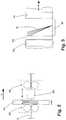
- the length section a, over which the cooling units K1, K2 and K3 arranged in the rolling scale each apply cooling fluid to the steel strip S, is limited to approximately 10% of the distance A, in which, as in the conveying direction F successively arranged rolling stands F5 and F6 in the FIGS. 2 and 3 represented, the mutually adjacent rolling stands F1 - F7 are respectively arranged.
- a respective spraying device Q1, Q2, Q3 is provided, which has a transverse direction to the conveying direction F and aligned in the direction of the respective cooling unit K1, K2, K3 high-pressure jet O at least on the upper side of the steel strip S, to drive there standing cooling fluid from the surface in question.
- the cooling unit K1 arranged between the fifth rolling stand F5 and the sixth rolling stand F6 of the hot rolling stand 2 is set up so that, provided the cooling unit K1 is switched on, the vertically downwardly directed cooling liquid jets it discharges reach from the rolling stand F5.
- the cooling unit K2 arranged between the sixth rolling stand F6 and the seventh rolling stand F7 of the hot rolling stand 2 is set up such that the cooling liquid jets it discharges, if the cooling unit K2 is switched on, reach the rolling stand F6 until they exit the rolling stand F6.
- the cooling unit K3 arranged in the conveying direction F behind the seventh roll stand F7 is set up so that, provided the cooling unit K3 is switched on, the cooling liquid jets it discharges extend to the rolling stand F7.
- At least one of the cooling units K1-K3 is in each case in operation. In the area of each non-active cooling unit can take place cooling in air.
- the hot strip is cooled to the respective required reel temperature HT.
- the thickness of the steel slabs processed in the rolling mill 2 is typically in the range of 180 to 270 mm in practice. Specifically, 255 mm thick slabs were produced in the embodiments described here from the specified in Table 1 steels E1, E2, E3, with a lying typically in the range of 800 - 1050 ° C hot rolling start temperature WAT entered into the hot roll stand 2 and there in a continuous succession in the first five rolling stands F1, F2, F3, F4, F5 were each hot rolled to a steel strip S. The thickness D of the steel strips S hot-rolled from the steels E1, E2, E3 was in each case 23 mm or 18 mm.
- the hot rolling start temperatures WAT which are respectively set concretely in the exemplary embodiments explained here, are given in Table 3. There are also indicated for each processed, produced from the respective steel E1, E2, E3 hot strip temperature TAF5 at the outlet of the fifth roll stand F5, the temperature WET at the outlet of the finishing train and the reel temperature HT.
- the steel strips S emerging from the fifth rolling stand F5 have likewise passed through the last two rolling stands F6 and F7 of the hot rolling stand 2.
- the work rolls were so far apart that the height of the nip limited by them was larger than the thickness D of the fifth Roll stand F5 emerging steel strip S.
- F rolling stands F6 and F7 of the rolling scale 2 no deformation of the steel strip S more.
- the cooling units K1 and K2 and all subsequent cooling units K3 - Kn were the cooling section 5 activated.
- the steel strip S emerging from the last active rolling stand F5 in the conveying direction F is seized by the cooling fluid jet of the cooling unit K1 after leaving the working gap A5 and has been intensively cooled on its way to the next rolling stand F6 until it has reached the entrance E6 of the rolling stand F6 , As soon as the steel strip S has passed through the working gap A6 of the inactive rolling stand F6, it has likewise been detected directly by the cooling fluid jet of the cooling unit K2 and has likewise been cooled further intensively until it has reached the inlet E7 of the inactive rolling stand F7.
- the active cooling Upon reaching the cooling stop temperature, the active cooling has been stopped and the steel strip S on the roller table 3 leaked until it has been reeled with a reel temperature of 450 - 650 ° C in the coiler 4 to form a coil.
- the cooling units K1 - Kn the cooling section 5 have at a cooling fluid pressure of more than 3 bar, specifically 3.2 bar, and a cooling fluid temperature of less than 40 ° C, specifically 25 ° C, over the cooling section 5, a total output of up to 1500 m 3 / h, specifically 1400 m 3 / h, cooling fluid reached.
- water has been used as the cooling fluid.
- other cooling fluids can be used to achieve the required cooling rate.
- Fig. 4 represented by the dashed line T2
- the temperature profile which is achieved in the production of a made of steel E1, 23 mm thick hot strip sample, when the cooling already begins according to the invention in the rolling scale 2, the cooling rate, however, is less than 80 K / s ,
- each temperature profile T1 - T4 the respective temperature TAF5, which has the hot strip at the output of the last active stand F5, by filled triangles, the respective temperature TAF6, which has the hot strip at the exit of the first inactive rolling stand F6, by unfilled triangles, the respective temperature WET, which had the respective steel strip S at the end of the rolling scale 2, symbolized by a square and the respective reel temperature by a circle.
- Table 2 stolen Steel strip thickness [mm] Do [° C] Rp0.5 [MPa] Rm [MPa] Matt fraction fraction [%] E1 18 -20 530 630 > 90 E1 23 0 530 630 > 85 E2 18 -10 530 630 > 85 E3 18 -20 650 650 > 87 stolen Steel strip thickness [mm] WAT [° C] TAF5 [° C] WET [° C] HT [° C] E1 18 900 820 730 550 E1 23 880 820 700 550 E2 18 900 820 730 550 E3 18 880 820 730 550
Landscapes
- Engineering & Computer Science (AREA)
- Chemical & Material Sciences (AREA)
- Mechanical Engineering (AREA)
- Physics & Mathematics (AREA)
- Thermal Sciences (AREA)
- Crystallography & Structural Chemistry (AREA)
- Materials Engineering (AREA)
- Metallurgy (AREA)
- Organic Chemistry (AREA)
- General Engineering & Computer Science (AREA)
- Metal Rolling (AREA)
- Heat Treatment Of Steel (AREA)
Claims (17)
- Installation pour laminer à chaud des feuillards d'acier (S), avec un train de laminage à chaud (2), qui comprend plusieurs cages de laminoir (F1 - F7) traversées l'une après l'autre dans la direction de transport (F) du feuillard d'acier à laminer à chaud (S), et avec une section de refroidissement (5) pour le refroidissement intensif du feuillard d'acier laminé à chaud (S) sortant de la dernière cage de laminoir (F7) du train de laminage (2), dans laquelle le début de la section de refroidissement (5) est déplacé, en considérant la direction de transport (F) du feuillard d'acier à laminer à chaud (S), avant la fin du train de laminage à chaud (2), dans laquelle la section de refroidissement (5) commence à la suite de la dernière cage de laminoir (F5) traversée activement avant l'entrée dans la section de refroidissement (5), dans laquelle il se produit un laminage à chaud du feuillard d'acier respectivement à laminer à chaud (S), dans laquelle la section de refroidissement (5) comprend plusieurs groupes de refroidissement (K1 - Kn) et dans laquelle un groupe de refroidissement (K1, K2, K3) est disposé respectivement dans la direction de transport (F) derrière la dernière cage de laminoir (F5) traversée avant l'entrée dans la section de refroidissement (5) et derrière chaque cage de laminoir (F6, F7) traversée à la suite de celle-ci, caractérisée en ce que le premier groupe de refroidissement (K1) de la section de refroidissement (5) dans la direction de transport (F) est disposé entre la cinquième cage de laminoir (F5) et la sixième cage de laminoir (F6) et le deuxième groupe de refroidissement (K2) de la section de refroidissement (5) est disposé entre la sixième cage de laminoir (F6) et la septième cage de laminoir (F7) du train de laminage (2).
- Installation selon la revendication 1, caractérisé en ce qu'au moins les groupes de refroidissement (K1 - K3) disposés à l'intérieur du train de laminage (2) sont formés par des groupes de refroidissement compacts.
- Installation selon la revendication 2, caractérisée en ce que la longueur mesurée dans la direction de transport (F) du feuillard d'acier à laminer à chaud (S), sur laquelle le groupe de refroidissement (K1, K2, K3) disposé respectivement derrière une cage de laminoir (F5, F6, F7) soumet respectivement le feuillard d'acier au fluide de refroidissement, vaut au maximum 25 % de la distance respective (A), à laquelle les cages de laminoir (F1 - F7) du train de laminage (2) disposées respectivement à proximité l'une de l'autre sont installées à la suite l'une de l'autre dans la direction de transport (F).
- Installation selon la revendication 3, caractérisée en ce que derrière, dans la direction de transport (F), au moins un des groupes de refroidissement (K1, K2) disposés entre deux cages de laminoir (F5, F6; F6, F7) disposées à proximité l'une de l'autre ou derrière, dans la direction de transport (F), le groupe de refroidissement (K3) disposé après la dernière cage de laminoir (F7) est disposé un dispositif de projection (8), qui dirige un jet de liquide (Q) sur le feuillard d'acier (S), afin de chasser du feuillard d'acier (S) le fluide de refroidissement présent sur le feuillard d'acier (8) avant l'entrée dans la cage de laminoir (F6, F7) traversée à la suite.
- Installation selon l'une quelconque des revendications précédentes, caractérisée en ce que les groupes de refroidissement (K4 - Kn) disposés à l'extérieur du train de laminage (2) sont formés par des groupes de refroidissement intensif.
- Installation selon l'une quelconque des revendications 2 à 5, caractérisée en ce que les groupes de refroidissement (K1 - Kn) de la section de refroidissement (5) peuvent être réglés séparément les uns des autres.
- Installation selon l'une quelconque des revendications précédentes, caractérisée en ce que la section de refroidissement (5) présente un débit de fluide de refroidissement d'au moins 1000 m3/h au total.
- Procédé pour laminer à chaud du feuillard d'acier destiné à la fabrication de tubes à paroi épaisse, caractérisé en ce qu'on le met en oeuvre sur une installation (1) configurée selon l'une quelconque des revendications 1 à 7 et en ce que, pendant le laminage à chaud dans la dernière cage de laminoir (F6, F7) vue dans la direction de transport (F), on ouvre l'emprise de laminage (A6, A7) à un point tel qu'à partir de cette cage de laminoir (F6, F7) il ne se produise plus aucune déformation du feuillard d'acier (S) dans le train de laminage à chaud (2), et que le feuillard d'acier (S) soit refroidi de façon accélérée, à la suite de la sortie de la cage de laminoir (F5, F6) traversée avant chaque première cage de laminoir ouverte (F6, F7), par exposition à un fluide de refroidissement avec une vitesse de refroidissement d'au moins 80 K/s.
- Procédé selon la revendication 8, caractérisé en ce que l'épaisseur finale (D) du feuillard d'acier (S) à la sortie du train de laminage à chaud (2) vaut au moins 15 mm.
- Procédé selon une des revendications 8 ou 9, caractérisé en ce que la vitesse finale de laminage à chaud vaut moins de 3 m/s.
- Procédé selon l'une quelconque des revendications 8 à 10, caractérisé en ce que la température initiale de laminage à chaud du feuillard d'acier (S) vaut plus de 800°C et moins de 1050°C.
- Procédé selon l'une quelconque des revendications 8 à 11, caractérisé en ce que la température de sortie, à laquelle le feuillard d'acier (S) entre dans la section de refroidissement (5) lorsqu'il quitte la dernière cage de laminoir (F5) par laquelle il est déformé à chaud, se situe entre 740°C et 900°C.
- Procédé selon l'une quelconque des revendications 8 à 12, caractérisé en ce que l'on interrompt le refroidissement du feuillard d'acier (S) à une température d'arrêt de refroidissement, qui se situe entre 500°C et 700°C.
- Procédé selon la revendication 13, caractérisé en ce que l'on maintient le feuillard d'acier (2) pendant 2 à 12 secondes à la température respective lorsque l'on atteint la température d'arrêt de refroidissement.
- Procédé selon l'une quelconque des revendications 8 à 14, caractérisé en ce que l'on bobine le feuillard d'acier (S) à une température de bobinage, qui se situe entre 450°C et 650°C.
- Procédé selon l'une quelconque des revendications 8 à 15, caractérisé en ce que l'épaisseur (D) du feuillard d'acier (S) à son entrée dans le train de laminage à chaud vaut 50 - 100 mm et elle vaut >15 - 25,5 mm lorsqu'il quitte le train de laminage à chaud.
- Procédé selon l'une quelconque des revendications 8 à 16, caractérisé en ce que le feuillard d'acier (S) est fabriqué en un acier qui, en plus du fer et des impuretés inévitables, se compose (en % en poids) de: C: ≤ 0,18 %, Si: ≤ 1,5 %, Mn: ≤ 2,5 %, P: 0,005 - 0,1 %, S: ≤ 0,03 %, N: ≤ 0,02 %, Cr: ≤ 0,5 %, Cu: ≤ 0,5 %, Ni: ≤ 0,5 %, Mo: ≤ 0,5 %, Al: ≤ 2 %, et jusqu'à 0,3 % au total d'un ou de plusieurs des éléments B, Nb, Ti, V, Zr, Ca.
Priority Applications (1)
| Application Number | Priority Date | Filing Date | Title |
|---|---|---|---|
| PL14736716T PL3016754T3 (pl) | 2013-07-03 | 2014-07-01 | Urządzenie i sposób walcowania na gorąco taśmy stalowej |
Applications Claiming Priority (2)
| Application Number | Priority Date | Filing Date | Title |
|---|---|---|---|
| DE102013107010.8A DE102013107010A1 (de) | 2013-07-03 | 2013-07-03 | Anlage und Verfahren zum Warmwalzen von Stahlband |
| PCT/EP2014/063955 WO2015000895A1 (fr) | 2013-07-03 | 2014-07-01 | Installation et procédé pour laminer à chaud des feuillards d'acier |
Publications (3)
| Publication Number | Publication Date |
|---|---|
| EP3016754A1 EP3016754A1 (fr) | 2016-05-11 |
| EP3016754B1 true EP3016754B1 (fr) | 2019-09-04 |
| EP3016754B2 EP3016754B2 (fr) | 2024-06-05 |
Family
ID=51162752
Family Applications (1)
| Application Number | Title | Priority Date | Filing Date |
|---|---|---|---|
| EP14736716.3A Active EP3016754B2 (fr) | 2013-07-03 | 2014-07-01 | Procédé pour laminer à chaud des feuillards d'acier |
Country Status (11)
| Country | Link |
|---|---|
| US (1) | US10335840B2 (fr) |
| EP (1) | EP3016754B2 (fr) |
| JP (1) | JP6450379B2 (fr) |
| KR (1) | KR102212807B1 (fr) |
| CN (1) | CN105392574B (fr) |
| CA (1) | CA2914540C (fr) |
| DE (1) | DE102013107010A1 (fr) |
| ES (1) | ES2756453T3 (fr) |
| MX (1) | MX364428B (fr) |
| PL (1) | PL3016754T3 (fr) |
| WO (1) | WO2015000895A1 (fr) |
Families Citing this family (8)
| Publication number | Priority date | Publication date | Assignee | Title |
|---|---|---|---|---|
| WO2017169939A1 (fr) * | 2016-03-31 | 2017-10-05 | Jfeスチール株式会社 | Tôle d'acier mince et tôle d'acier plaquée, procédé de production de tôle d'acier laminée à chaud, procédé de production de tôle d'acier totalement dure laminée à froid, procédé de production de tôle traitée thermiquement, procédé de production de tôle d'acier mince et procédé de production de tôle d'acier plaquée |
| KR102259597B1 (ko) * | 2017-02-16 | 2021-06-02 | 닛폰세이테츠 가부시키가이샤 | 열간 압연 강판 및 그의 제조 방법 |
| DE102019220033A1 (de) | 2019-03-18 | 2020-09-24 | Sms Group Gmbh | Anlage und Verfahren zur Herstellung von metallischem Warmband |
| CN113042539B (zh) * | 2021-03-25 | 2022-10-14 | 德龙钢铁有限公司 | 一种用于热轧带钢微观组织精细控制的冷却方法 |
| EP4101552A1 (fr) | 2021-06-09 | 2022-12-14 | Primetals Technologies Austria GmbH | Procédé de fabrication d'acier micro-allié, acier micro-allié fabriqué selon le procédé et installation combinée de coulée et de laminage |
| AT525283B1 (de) * | 2021-10-29 | 2023-02-15 | Primetals Technologies Austria GmbH | Verfahren zur Herstellung eines Dualphasenstahlbands in einer Gieß-Walz-Verbundanlage, ein mit dem Verfahren hergestelltes Dualphasenstahlband und eine Gieß-Walz-Verbundanlage |
| CN115069771B (zh) * | 2022-06-24 | 2026-03-17 | 湖南华菱涟源钢铁有限公司 | 热轧钢卷及其制造方法 |
| DE102022124366A1 (de) | 2022-09-22 | 2024-03-28 | Thyssenkrupp Steel Europe Ag | Verfahren zur Herstellung eines warmgewalzten Stahlflachprodukts zum Einsatz in der Rohrfertigung |
Citations (6)
| Publication number | Priority date | Publication date | Assignee | Title |
|---|---|---|---|---|
| EP1038978A1 (fr) | 1999-03-25 | 2000-09-27 | Thyssen Krupp Stahl AG | Procédé et installation pour produire une bande laminée à chaud |
| EP1279445A1 (fr) | 2001-03-16 | 2003-01-29 | Nakayama Steel Works, Ltd. | Laminoir a chaud et procede de laminage a chaud |
| DE102007058709A1 (de) | 2007-08-04 | 2009-02-05 | Sms Demag Ag | Verfahren zum Herstellen eines Bandes aus Stahl |
| JP2009241113A (ja) | 2008-03-31 | 2009-10-22 | Nippon Steel Corp | 熱延鋼板の製造方法 |
| WO2013030945A1 (fr) | 2011-08-30 | 2013-03-07 | 東芝三菱電機産業システム株式会社 | Dispositif économiseur d'énergie pour laminoir |
| EP2692894A1 (fr) | 2011-03-31 | 2014-02-05 | Nippon Steel & Sumitomo Metal Corporation | Plaque d'acier à haute résistance laminée à chaud contenant de la bainite avec une excellente usinabilité isotrope, et son procédé de production |
Family Cites Families (30)
| Publication number | Priority date | Publication date | Assignee | Title |
|---|---|---|---|---|
| US1038978A (en) * | 1911-09-28 | 1912-09-17 | Cullen Rogers Smith | Stalk-puller. |
| JPS57112918A (en) * | 1980-12-29 | 1982-07-14 | Kawasaki Steel Corp | Hot rolling method |
| JP2970509B2 (ja) | 1995-11-21 | 1999-11-02 | 住友金属工業株式会社 | 鋼帯上冷却水の除去方法および装置 |
| DE19725434C2 (de) | 1997-06-16 | 1999-08-19 | Schloemann Siemag Ag | Verfahren zum Walzen von Warmbreitband in einer CSP-Anlage |
| JPH11267730A (ja) * | 1998-03-24 | 1999-10-05 | Kawasaki Steel Corp | 熱延鋼板の温度制御装置及びその方法 |
| JPH11290932A (ja) * | 1998-04-16 | 1999-10-26 | Nippon Steel Corp | 熱間圧延方法及び熱間圧延機 |
| JP3413183B2 (ja) | 2001-09-20 | 2003-06-03 | 株式会社中山製鋼所 | 連続熱間圧延方法および連続熱間圧延設備 |
| US7076983B2 (en) | 2001-03-16 | 2006-07-18 | Nakayama Steel Works, Ltd. | Apparatus and method for hot rolling |
| JP3705233B2 (ja) | 2002-04-09 | 2005-10-12 | 住友金属工業株式会社 | 熱延鋼板の製造方法 |
| US20050115649A1 (en) | 2003-03-27 | 2005-06-02 | Tokarz Christopher A. | Thermomechanical processing routes in compact strip production of high-strength low-alloy steel |
| JP4770235B2 (ja) | 2004-03-30 | 2011-09-14 | Jfeスチール株式会社 | 延性と疲労亀裂伝播特性に優れた鋼材の製造方法 |
| WO2006137187A1 (fr) * | 2005-06-23 | 2006-12-28 | Nippon Steel Corporation | Dispositif de refroidissement pour plaque d'acier epaisse |
| DE102006002505A1 (de) | 2005-10-31 | 2007-05-03 | Sms Demag Ag | Verfahren und Fertigwalzstraße zum Warmwalzen von Eingangsmaterial |
| JP2007331017A (ja) | 2006-06-16 | 2007-12-27 | Nakayama Steel Works Ltd | 熱延鋼板の製造方法および製造装置 |
| JP4586791B2 (ja) * | 2006-10-30 | 2010-11-24 | Jfeスチール株式会社 | 熱延鋼帯の冷却方法 |
| KR101484461B1 (ko) * | 2006-12-21 | 2015-01-20 | 코닌클리케 필립스 엔.브이. | 성형된 파장 변환기를 가지는 발광 장치 |
| JP4848984B2 (ja) | 2007-03-22 | 2011-12-28 | 住友金属工業株式会社 | 熱延鋼板の製造方法及び製造装置 |
| DE102007031333A1 (de) * | 2007-07-05 | 2009-01-15 | Siemens Ag | Walzen eines Bandes in einer Walzstraße unter Nutzung des letzen Gerüsts der Walzstraße als Zugverringerer |
| JP4907587B2 (ja) | 2008-03-31 | 2012-03-28 | 新日本製鐵株式会社 | 鋼板冷却設備及び鋼板冷却方法 |
| JP4870110B2 (ja) | 2008-03-31 | 2012-02-08 | 新日本製鐵株式会社 | 鋼板冷却装置 |
| BRPI0913046A2 (pt) | 2008-05-26 | 2020-12-15 | Nippon Steel Corporation | Chapa de aço laminada a quente de alta resistência para uso em oleodutos, excelente em tenacidade a baixa temperatura e performance de interrupção de fratura dúctil e método de produção da mesma |
| DE102009017304A1 (de) * | 2009-04-11 | 2010-10-21 | Fresenius Medical Care Deutschland Gmbh | Vorrichtung und Verfahren zur Messung eines Blutbestandteils im Blut für eine extrakorporale Blutbehandlungsvorrichtung |
| BRPI1011945B1 (pt) * | 2009-06-30 | 2020-11-10 | Nippon Steel Corporation | aparelho e método de fabricação de uma lâmina de aço laminada a quente |
| JP5577655B2 (ja) * | 2009-09-04 | 2014-08-27 | Jfeスチール株式会社 | 熱延鋼板の冷却設備および冷却方法 |
| CN102781598B (zh) * | 2010-03-11 | 2015-09-23 | 新日铁住金株式会社 | 热轧钢板的制造方法及制造装置 |
| JP5646261B2 (ja) * | 2010-09-22 | 2014-12-24 | 三菱日立製鉄機械株式会社 | 熱延鋼帯の冷却装置 |
| JP5903869B2 (ja) | 2011-12-19 | 2016-04-13 | Jfeスチール株式会社 | 熱間圧延ラインにおけるミルペーシング制御方法 |
| JP5878446B2 (ja) * | 2012-09-12 | 2016-03-08 | 新日鐵住金株式会社 | ノズルヘッダ、冷却装置、熱延鋼板の製造装置、および熱延鋼板の製造方法 |
| JP2016512174A (ja) * | 2013-03-15 | 2016-04-25 | ノベリス・インコーポレイテッドNovelis Inc. | 熱間金属圧延における指向性潤滑のための製造方法および装置 |
| KR101653515B1 (ko) * | 2013-03-15 | 2016-09-01 | 노벨리스 인크. | 열간 금속 압연에서의 타겟팅된 냉각을 위한 제조 방법 및 장치 |
-
2013
- 2013-07-03 DE DE102013107010.8A patent/DE102013107010A1/de not_active Withdrawn
-
2014
- 2014-07-01 PL PL14736716T patent/PL3016754T3/pl unknown
- 2014-07-01 KR KR1020167002862A patent/KR102212807B1/ko not_active Expired - Fee Related
- 2014-07-01 EP EP14736716.3A patent/EP3016754B2/fr active Active
- 2014-07-01 WO PCT/EP2014/063955 patent/WO2015000895A1/fr not_active Ceased
- 2014-07-01 JP JP2016522581A patent/JP6450379B2/ja not_active Expired - Fee Related
- 2014-07-01 CN CN201480038407.1A patent/CN105392574B/zh not_active Expired - Fee Related
- 2014-07-01 MX MX2015016716A patent/MX364428B/es active IP Right Grant
- 2014-07-01 ES ES14736716T patent/ES2756453T3/es active Active
- 2014-07-01 CA CA2914540A patent/CA2914540C/fr not_active Expired - Fee Related
- 2014-07-01 US US14/902,812 patent/US10335840B2/en not_active Expired - Fee Related
Patent Citations (7)
| Publication number | Priority date | Publication date | Assignee | Title |
|---|---|---|---|---|
| EP1038978A1 (fr) | 1999-03-25 | 2000-09-27 | Thyssen Krupp Stahl AG | Procédé et installation pour produire une bande laminée à chaud |
| EP1038978B1 (fr) | 1999-03-25 | 2004-05-12 | ThyssenKrupp Stahl AG | Procédé pour produire une bande laminée à chaud |
| EP1279445A1 (fr) | 2001-03-16 | 2003-01-29 | Nakayama Steel Works, Ltd. | Laminoir a chaud et procede de laminage a chaud |
| DE102007058709A1 (de) | 2007-08-04 | 2009-02-05 | Sms Demag Ag | Verfahren zum Herstellen eines Bandes aus Stahl |
| JP2009241113A (ja) | 2008-03-31 | 2009-10-22 | Nippon Steel Corp | 熱延鋼板の製造方法 |
| EP2692894A1 (fr) | 2011-03-31 | 2014-02-05 | Nippon Steel & Sumitomo Metal Corporation | Plaque d'acier à haute résistance laminée à chaud contenant de la bainite avec une excellente usinabilité isotrope, et son procédé de production |
| WO2013030945A1 (fr) | 2011-08-30 | 2013-03-07 | 東芝三菱電機産業システム株式会社 | Dispositif économiseur d'énergie pour laminoir |
Non-Patent Citations (2)
| Title |
|---|
| E. MUTHMANN, ET AL: "Manufacturing of Large Steel Components for Nord Stream Project", 3R INTERNATIONAL. SPECIAL EDITION. STEEL PIPES, 1 February 2010 (2010-02-01), pages 26 - 31, XP055757377 |
| VOLKER SCHWINN, ET AL: "Recent Developments and Applications of TMCP Steel Plates", 2011 INT. SYMPOSIUM ON THE RECENT DEVELOPMENTS IN PLATE STEELS, 1 January 2011 (2011-01-01), pages 1 - 11, XP055757371 |
Also Published As
| Publication number | Publication date |
|---|---|
| DE102013107010A1 (de) | 2015-01-22 |
| EP3016754B2 (fr) | 2024-06-05 |
| CA2914540A1 (fr) | 2015-01-08 |
| EP3016754A1 (fr) | 2016-05-11 |
| CN105392574A (zh) | 2016-03-09 |
| KR102212807B1 (ko) | 2021-02-05 |
| JP2016530099A (ja) | 2016-09-29 |
| US20160151814A1 (en) | 2016-06-02 |
| ES2756453T3 (es) | 2020-04-27 |
| MX364428B (es) | 2019-04-25 |
| WO2015000895A1 (fr) | 2015-01-08 |
| KR20160030218A (ko) | 2016-03-16 |
| US10335840B2 (en) | 2019-07-02 |
| PL3016754T3 (pl) | 2020-02-28 |
| JP6450379B2 (ja) | 2019-01-09 |
| CN105392574B (zh) | 2019-01-18 |
| CA2914540C (fr) | 2018-01-16 |
Similar Documents
| Publication | Publication Date | Title |
|---|---|---|
| EP3016754B1 (fr) | Installation et procédé pour laminer à chaud des feuillards d'acier | |
| DE69102280T2 (de) | Verfahren und anlage zum herstellen von direkt einer warmwalzstrasse erzeugter stahlbandcoils mit kaltwalzeigenschaften. | |
| AT512399B1 (de) | Verfahren zum Herstellen eines mikrolegierten Röhrenstahls in einer Gieß-Walz-Verbundanlage und mikrolegierter Röhrenstahl | |
| EP2991783B1 (fr) | Procédé de fabrication d'une bande métallique | |
| AT504782A4 (de) | Verfahren zur herstellung eines warmgewalzten stahlbandes und kombinierte giess- und walzanlage zur durchführung des verfahrens | |
| EP2507399B1 (fr) | Laminoir à chaud et procédé de laminage à chaud d'un feuillard ou d'une tôle | |
| EP2651578B1 (fr) | Train de laminoir pour la production d'acier tubulaire et de bandes minces | |
| DE2454163A1 (de) | Verfahren zur steuerung der temperatur von stahl waehrend des heisswalzens auf einer kontinuierlichen heisswalzvorrichtung | |
| AT509707A4 (de) | Verfahren zum warmwalzen von stahlbändern und warmwalzstrasse | |
| WO2012004205A1 (fr) | Procédé et chaîne de production destinés à fabriquer un produit plat en acier laminé à froid à partir d'un acier inoxydable | |
| EP3206808B1 (fr) | Installation et procédé de fabrication de tôles fortes | |
| EP3941655B1 (fr) | Installation et procédé pour fabriquer un feuillard à chaud métallique | |
| WO2022258376A1 (fr) | Procédé de fabrication d'un acier micro-allié, acier micro-allié produit à l'aide du procédé et installation combinée de coulée/laminage | |
| DE60004948T2 (de) | Verfahren zur kontinuierlichen herstellung eines metallbandes | |
| EP1525060B1 (fr) | Procede et dispositif de fabrication en continu de bandes metalliques | |
| EP1038978B1 (fr) | Procédé pour produire une bande laminée à chaud | |
| EP2379244B1 (fr) | Procédé et dispositif de décalaminage d'une bande de métal | |
| AT525283B1 (de) | Verfahren zur Herstellung eines Dualphasenstahlbands in einer Gieß-Walz-Verbundanlage, ein mit dem Verfahren hergestelltes Dualphasenstahlband und eine Gieß-Walz-Verbundanlage | |
| EP4347905B1 (fr) | Système et procédé de production de produits en acier sous forme de fils et/ou de barres | |
| EP0970256B1 (fr) | Laminage a chaud de feuillard d'acier | |
| DE102023210877A1 (de) | Vorrichtung und Verfahren zur Herstellung eines warmgewalzten Metallbands | |
| WO2025131409A1 (fr) | Installation de coulée et de laminage combinée pour la mise en forme primaire d'un matériau de laminage métallique et le laminage à chaud d'une bande de matériau, et procédé pour la mise en forme primaire d'un matériau de laminage métallique et pour le laminage à chaud direct | |
| WO2022194467A1 (fr) | Installation et procédé de laminage à froid d'une bande métallique à partir d'acier | |
| DE102009060828A1 (de) | Walzanlage zum kontinuierlichen Walzen von bandförmigem Walzgut | |
| EP3670682A1 (fr) | Fabrication d'une bande métallique à une structure mixte de martensite-austénite |
Legal Events
| Date | Code | Title | Description |
|---|---|---|---|
| PUAI | Public reference made under article 153(3) epc to a published international application that has entered the european phase |
Free format text: ORIGINAL CODE: 0009012 |
|
| 17P | Request for examination filed |
Effective date: 20151105 |
|
| AK | Designated contracting states |
Kind code of ref document: A1 Designated state(s): AL AT BE BG CH CY CZ DE DK EE ES FI FR GB GR HR HU IE IS IT LI LT LU LV MC MK MT NL NO PL PT RO RS SE SI SK SM TR |
|
| AX | Request for extension of the european patent |
Extension state: BA ME |
|
| RIN1 | Information on inventor provided before grant (corrected) |
Inventor name: FISCHER, HERIBERT Inventor name: ZAUM, ANDREAS Inventor name: SCHMITT, CASPAR |
|
| DAX | Request for extension of the european patent (deleted) | ||
| STAA | Information on the status of an ep patent application or granted ep patent |
Free format text: STATUS: EXAMINATION IS IN PROGRESS |
|
| 17Q | First examination report despatched |
Effective date: 20170322 |
|
| GRAP | Despatch of communication of intention to grant a patent |
Free format text: ORIGINAL CODE: EPIDOSNIGR1 |
|
| STAA | Information on the status of an ep patent application or granted ep patent |
Free format text: STATUS: GRANT OF PATENT IS INTENDED |
|
| INTG | Intention to grant announced |
Effective date: 20190206 |
|
| GRAS | Grant fee paid |
Free format text: ORIGINAL CODE: EPIDOSNIGR3 |
|
| GRAJ | Information related to disapproval of communication of intention to grant by the applicant or resumption of examination proceedings by the epo deleted |
Free format text: ORIGINAL CODE: EPIDOSDIGR1 |
|
| GRAL | Information related to payment of fee for publishing/printing deleted |
Free format text: ORIGINAL CODE: EPIDOSDIGR3 |
|
| STAA | Information on the status of an ep patent application or granted ep patent |
Free format text: STATUS: EXAMINATION IS IN PROGRESS |
|
| INTC | Intention to grant announced (deleted) | ||
| GRAR | Information related to intention to grant a patent recorded |
Free format text: ORIGINAL CODE: EPIDOSNIGR71 |
|
| STAA | Information on the status of an ep patent application or granted ep patent |
Free format text: STATUS: GRANT OF PATENT IS INTENDED |
|
| GRAA | (expected) grant |
Free format text: ORIGINAL CODE: 0009210 |
|
| STAA | Information on the status of an ep patent application or granted ep patent |
Free format text: STATUS: THE PATENT HAS BEEN GRANTED |
|
| INTG | Intention to grant announced |
Effective date: 20190719 |
|
| AK | Designated contracting states |
Kind code of ref document: B1 Designated state(s): AL AT BE BG CH CY CZ DE DK EE ES FI FR GB GR HR HU IE IS IT LI LT LU LV MC MK MT NL NO PL PT RO RS SE SI SK SM TR |
|
| REG | Reference to a national code |
Ref country code: GB Ref legal event code: FG4D Free format text: NOT ENGLISH |
|
| REG | Reference to a national code |
Ref country code: CH Ref legal event code: EP |
|
| REG | Reference to a national code |
Ref country code: AT Ref legal event code: REF Ref document number: 1174634 Country of ref document: AT Kind code of ref document: T Effective date: 20190915 |
|
| REG | Reference to a national code |
Ref country code: DE Ref legal event code: R096 Ref document number: 502014012574 Country of ref document: DE |
|
| REG | Reference to a national code |
Ref country code: IE Ref legal event code: FG4D Free format text: LANGUAGE OF EP DOCUMENT: GERMAN |
|
| REG | Reference to a national code |
Ref country code: SE Ref legal event code: TRGR |
|
| REG | Reference to a national code |
Ref country code: NL Ref legal event code: FP |
|
| REG | Reference to a national code |
Ref country code: LT Ref legal event code: MG4D |
|
| PG25 | Lapsed in a contracting state [announced via postgrant information from national office to epo] |
Ref country code: LT Free format text: LAPSE BECAUSE OF FAILURE TO SUBMIT A TRANSLATION OF THE DESCRIPTION OR TO PAY THE FEE WITHIN THE PRESCRIBED TIME-LIMIT Effective date: 20190904 Ref country code: BG Free format text: LAPSE BECAUSE OF FAILURE TO SUBMIT A TRANSLATION OF THE DESCRIPTION OR TO PAY THE FEE WITHIN THE PRESCRIBED TIME-LIMIT Effective date: 20191204 Ref country code: HR Free format text: LAPSE BECAUSE OF FAILURE TO SUBMIT A TRANSLATION OF THE DESCRIPTION OR TO PAY THE FEE WITHIN THE PRESCRIBED TIME-LIMIT Effective date: 20190904 Ref country code: NO Free format text: LAPSE BECAUSE OF FAILURE TO SUBMIT A TRANSLATION OF THE DESCRIPTION OR TO PAY THE FEE WITHIN THE PRESCRIBED TIME-LIMIT Effective date: 20191204 |
|
| PG25 | Lapsed in a contracting state [announced via postgrant information from national office to epo] |
Ref country code: LV Free format text: LAPSE BECAUSE OF FAILURE TO SUBMIT A TRANSLATION OF THE DESCRIPTION OR TO PAY THE FEE WITHIN THE PRESCRIBED TIME-LIMIT Effective date: 20190904 Ref country code: RS Free format text: LAPSE BECAUSE OF FAILURE TO SUBMIT A TRANSLATION OF THE DESCRIPTION OR TO PAY THE FEE WITHIN THE PRESCRIBED TIME-LIMIT Effective date: 20190904 Ref country code: GR Free format text: LAPSE BECAUSE OF FAILURE TO SUBMIT A TRANSLATION OF THE DESCRIPTION OR TO PAY THE FEE WITHIN THE PRESCRIBED TIME-LIMIT Effective date: 20191205 Ref country code: AL Free format text: LAPSE BECAUSE OF FAILURE TO SUBMIT A TRANSLATION OF THE DESCRIPTION OR TO PAY THE FEE WITHIN THE PRESCRIBED TIME-LIMIT Effective date: 20190904 |
|
| REG | Reference to a national code |
Ref country code: ES Ref legal event code: FG2A Ref document number: 2756453 Country of ref document: ES Kind code of ref document: T3 Effective date: 20200427 |
|
| PG25 | Lapsed in a contracting state [announced via postgrant information from national office to epo] |
Ref country code: EE Free format text: LAPSE BECAUSE OF FAILURE TO SUBMIT A TRANSLATION OF THE DESCRIPTION OR TO PAY THE FEE WITHIN THE PRESCRIBED TIME-LIMIT Effective date: 20190904 Ref country code: RO Free format text: LAPSE BECAUSE OF FAILURE TO SUBMIT A TRANSLATION OF THE DESCRIPTION OR TO PAY THE FEE WITHIN THE PRESCRIBED TIME-LIMIT Effective date: 20190904 Ref country code: PT Free format text: LAPSE BECAUSE OF FAILURE TO SUBMIT A TRANSLATION OF THE DESCRIPTION OR TO PAY THE FEE WITHIN THE PRESCRIBED TIME-LIMIT Effective date: 20200106 |
|
| PG25 | Lapsed in a contracting state [announced via postgrant information from national office to epo] |
Ref country code: SM Free format text: LAPSE BECAUSE OF FAILURE TO SUBMIT A TRANSLATION OF THE DESCRIPTION OR TO PAY THE FEE WITHIN THE PRESCRIBED TIME-LIMIT Effective date: 20190904 Ref country code: SK Free format text: LAPSE BECAUSE OF FAILURE TO SUBMIT A TRANSLATION OF THE DESCRIPTION OR TO PAY THE FEE WITHIN THE PRESCRIBED TIME-LIMIT Effective date: 20190904 Ref country code: IS Free format text: LAPSE BECAUSE OF FAILURE TO SUBMIT A TRANSLATION OF THE DESCRIPTION OR TO PAY THE FEE WITHIN THE PRESCRIBED TIME-LIMIT Effective date: 20200224 |
|
| REG | Reference to a national code |
Ref country code: DE Ref legal event code: R026 Ref document number: 502014012574 Country of ref document: DE |
|
| PLBI | Opposition filed |
Free format text: ORIGINAL CODE: 0009260 |
|
| PLAX | Notice of opposition and request to file observation + time limit sent |
Free format text: ORIGINAL CODE: EPIDOSNOBS2 |
|
| REG | Reference to a national code |
Ref country code: FI Ref legal event code: MDE Opponent name: SMS GROUP GMBH Ref country code: FI Ref legal event code: MDE Opponent name: ARCELORMITTAL |
|
| 26 | Opposition filed |
Opponent name: SMS GROUP GMBH Effective date: 20200604 Opponent name: ARCELORMITTAL Effective date: 20200603 |
|
| PG2D | Information on lapse in contracting state deleted |
Ref country code: IS |
|
| PG25 | Lapsed in a contracting state [announced via postgrant information from national office to epo] |
Ref country code: IS Free format text: LAPSE BECAUSE OF FAILURE TO SUBMIT A TRANSLATION OF THE DESCRIPTION OR TO PAY THE FEE WITHIN THE PRESCRIBED TIME-LIMIT Effective date: 20200105 Ref country code: DK Free format text: LAPSE BECAUSE OF FAILURE TO SUBMIT A TRANSLATION OF THE DESCRIPTION OR TO PAY THE FEE WITHIN THE PRESCRIBED TIME-LIMIT Effective date: 20190904 |
|
| PG25 | Lapsed in a contracting state [announced via postgrant information from national office to epo] |
Ref country code: SI Free format text: LAPSE BECAUSE OF FAILURE TO SUBMIT A TRANSLATION OF THE DESCRIPTION OR TO PAY THE FEE WITHIN THE PRESCRIBED TIME-LIMIT Effective date: 20190904 |
|
| PGFP | Annual fee paid to national office [announced via postgrant information from national office to epo] |
Ref country code: PL Payment date: 20200622 Year of fee payment: 7 |
|
| PLAF | Information modified related to communication of a notice of opposition and request to file observations + time limit |
Free format text: ORIGINAL CODE: EPIDOSCOBS2 |
|
| PGFP | Annual fee paid to national office [announced via postgrant information from national office to epo] |
Ref country code: ES Payment date: 20200922 Year of fee payment: 7 Ref country code: CZ Payment date: 20200701 Year of fee payment: 7 Ref country code: GB Payment date: 20200727 Year of fee payment: 7 |
|
| PLBB | Reply of patent proprietor to notice(s) of opposition received |
Free format text: ORIGINAL CODE: EPIDOSNOBS3 |
|
| PGFP | Annual fee paid to national office [announced via postgrant information from national office to epo] |
Ref country code: IT Payment date: 20200724 Year of fee payment: 7 |
|
| PG25 | Lapsed in a contracting state [announced via postgrant information from national office to epo] |
Ref country code: MC Free format text: LAPSE BECAUSE OF FAILURE TO SUBMIT A TRANSLATION OF THE DESCRIPTION OR TO PAY THE FEE WITHIN THE PRESCRIBED TIME-LIMIT Effective date: 20190904 |
|
| REG | Reference to a national code |
Ref country code: CH Ref legal event code: PL |
|
| PG25 | Lapsed in a contracting state [announced via postgrant information from national office to epo] |
Ref country code: IE Free format text: LAPSE BECAUSE OF NON-PAYMENT OF DUE FEES Effective date: 20200701 Ref country code: LI Free format text: LAPSE BECAUSE OF NON-PAYMENT OF DUE FEES Effective date: 20200731 Ref country code: CH Free format text: LAPSE BECAUSE OF NON-PAYMENT OF DUE FEES Effective date: 20200731 Ref country code: LU Free format text: LAPSE BECAUSE OF NON-PAYMENT OF DUE FEES Effective date: 20200701 |
|
| PLAB | Opposition data, opponent's data or that of the opponent's representative modified |
Free format text: ORIGINAL CODE: 0009299OPPO |
|
| R26 | Opposition filed (corrected) |
Opponent name: ARCELORMITTAL Effective date: 20200603 |
|
| REG | Reference to a national code |
Ref country code: CH Ref legal event code: PK Free format text: BERICHTIGUNGEN |
|
| RIC2 | Information provided on ipc code assigned after grant |
Ipc: C21D 8/02 20060101AFI20211221BHEP |
|
| PG25 | Lapsed in a contracting state [announced via postgrant information from national office to epo] |
Ref country code: CZ Free format text: LAPSE BECAUSE OF NON-PAYMENT OF DUE FEES Effective date: 20210701 |
|
| GBPC | Gb: european patent ceased through non-payment of renewal fee |
Effective date: 20210701 |
|
| APBM | Appeal reference recorded |
Free format text: ORIGINAL CODE: EPIDOSNREFNO |
|
| APBP | Date of receipt of notice of appeal recorded |
Free format text: ORIGINAL CODE: EPIDOSNNOA2O |
|
| APAH | Appeal reference modified |
Free format text: ORIGINAL CODE: EPIDOSCREFNO |
|
| PG25 | Lapsed in a contracting state [announced via postgrant information from national office to epo] |
Ref country code: GB Free format text: LAPSE BECAUSE OF NON-PAYMENT OF DUE FEES Effective date: 20210701 |
|
| PG25 | Lapsed in a contracting state [announced via postgrant information from national office to epo] |
Ref country code: MT Free format text: LAPSE BECAUSE OF FAILURE TO SUBMIT A TRANSLATION OF THE DESCRIPTION OR TO PAY THE FEE WITHIN THE PRESCRIBED TIME-LIMIT Effective date: 20190904 Ref country code: CY Free format text: LAPSE BECAUSE OF FAILURE TO SUBMIT A TRANSLATION OF THE DESCRIPTION OR TO PAY THE FEE WITHIN THE PRESCRIBED TIME-LIMIT Effective date: 20190904 |
|
| APBQ | Date of receipt of statement of grounds of appeal recorded |
Free format text: ORIGINAL CODE: EPIDOSNNOA3O |
|
| PG25 | Lapsed in a contracting state [announced via postgrant information from national office to epo] |
Ref country code: MK Free format text: LAPSE BECAUSE OF FAILURE TO SUBMIT A TRANSLATION OF THE DESCRIPTION OR TO PAY THE FEE WITHIN THE PRESCRIBED TIME-LIMIT Effective date: 20190904 |
|
| PG25 | Lapsed in a contracting state [announced via postgrant information from national office to epo] |
Ref country code: IT Free format text: LAPSE BECAUSE OF NON-PAYMENT OF DUE FEES Effective date: 20210701 |
|
| PGFP | Annual fee paid to national office [announced via postgrant information from national office to epo] |
Ref country code: TR Payment date: 20220629 Year of fee payment: 9 |
|
| REG | Reference to a national code |
Ref country code: ES Ref legal event code: FD2A Effective date: 20220905 |
|
| PG25 | Lapsed in a contracting state [announced via postgrant information from national office to epo] |
Ref country code: ES Free format text: LAPSE BECAUSE OF NON-PAYMENT OF DUE FEES Effective date: 20210702 |
|
| PGFP | Annual fee paid to national office [announced via postgrant information from national office to epo] |
Ref country code: FI Payment date: 20220721 Year of fee payment: 9 |
|
| P01 | Opt-out of the competence of the unified patent court (upc) registered |
Effective date: 20230526 |
|
| PG25 | Lapsed in a contracting state [announced via postgrant information from national office to epo] |
Ref country code: PL Free format text: LAPSE BECAUSE OF NON-PAYMENT OF DUE FEES Effective date: 20210701 |
|
| REG | Reference to a national code |
Ref country code: DE Ref legal event code: R084 Ref document number: 502014012574 Country of ref document: DE |
|
| APBU | Appeal procedure closed |
Free format text: ORIGINAL CODE: EPIDOSNNOA9O |
|
| REG | Reference to a national code |
Ref country code: CH Ref legal event code: PK Free format text: TITEL |
|
| PG25 | Lapsed in a contracting state [announced via postgrant information from national office to epo] |
Ref country code: FI Free format text: LAPSE BECAUSE OF NON-PAYMENT OF DUE FEES Effective date: 20230701 |
|
| PUAH | Patent maintained in amended form |
Free format text: ORIGINAL CODE: 0009272 |
|
| STAA | Information on the status of an ep patent application or granted ep patent |
Free format text: STATUS: PATENT MAINTAINED AS AMENDED |
|
| 27A | Patent maintained in amended form |
Effective date: 20240605 |
|
| AK | Designated contracting states |
Kind code of ref document: B2 Designated state(s): AL AT BE BG CH CY CZ DE DK EE ES FI FR GB GR HR HU IE IS IT LI LT LU LV MC MK MT NL NO PL PT RO RS SE SI SK SM TR |
|
| REG | Reference to a national code |
Ref country code: DE Ref legal event code: R102 Ref document number: 502014012574 Country of ref document: DE |
|
| REG | Reference to a national code |
Ref country code: NL Ref legal event code: FP |
|
| PGFP | Annual fee paid to national office [announced via postgrant information from national office to epo] |
Ref country code: NL Payment date: 20240719 Year of fee payment: 11 |
|
| PGFP | Annual fee paid to national office [announced via postgrant information from national office to epo] |
Ref country code: DE Payment date: 20240719 Year of fee payment: 11 |
|
| PGFP | Annual fee paid to national office [announced via postgrant information from national office to epo] |
Ref country code: BE Payment date: 20240719 Year of fee payment: 11 |
|
| PGFP | Annual fee paid to national office [announced via postgrant information from national office to epo] |
Ref country code: FR Payment date: 20240730 Year of fee payment: 11 |
|
| PGFP | Annual fee paid to national office [announced via postgrant information from national office to epo] |
Ref country code: AT Payment date: 20240722 Year of fee payment: 11 |
|
| PGFP | Annual fee paid to national office [announced via postgrant information from national office to epo] |
Ref country code: SE Payment date: 20240719 Year of fee payment: 11 |
|
| REG | Reference to a national code |
Ref country code: SE Ref legal event code: NAV |
|
| REG | Reference to a national code |
Ref country code: DE Ref legal event code: R119 Ref document number: 502014012574 Country of ref document: DE |
|
| REG | Reference to a national code |
Ref country code: NL Ref legal event code: MM Effective date: 20250801 |
|
| REG | Reference to a national code |
Ref country code: AT Ref legal event code: MM01 Ref document number: 1174634 Country of ref document: AT Kind code of ref document: T Effective date: 20250701 |
|
| REG | Reference to a national code |
Ref country code: BE Ref legal event code: MM Effective date: 20250731 |
|
| PG25 | Lapsed in a contracting state [announced via postgrant information from national office to epo] |
Ref country code: DE Free format text: LAPSE BECAUSE OF NON-PAYMENT OF DUE FEES Effective date: 20260203 |
|
| PG25 | Lapsed in a contracting state [announced via postgrant information from national office to epo] |
Ref country code: AT Free format text: LAPSE BECAUSE OF NON-PAYMENT OF DUE FEES Effective date: 20250701 |
|
| PG25 | Lapsed in a contracting state [announced via postgrant information from national office to epo] |
Ref country code: BE Free format text: LAPSE BECAUSE OF NON-PAYMENT OF DUE FEES Effective date: 20250731 |
|
| PG25 | Lapsed in a contracting state [announced via postgrant information from national office to epo] |
Ref country code: NL Free format text: LAPSE BECAUSE OF NON-PAYMENT OF DUE FEES Effective date: 20250801 |
|
| PG25 | Lapsed in a contracting state [announced via postgrant information from national office to epo] |
Ref country code: FR Free format text: LAPSE BECAUSE OF NON-PAYMENT OF DUE FEES Effective date: 20250731 |