EP3016839B1 - Gegengewichtseinheit eines steuerknüppel - Google Patents
Gegengewichtseinheit eines steuerknüppel Download PDFInfo
- Publication number
- EP3016839B1 EP3016839B1 EP14736924.3A EP14736924A EP3016839B1 EP 3016839 B1 EP3016839 B1 EP 3016839B1 EP 14736924 A EP14736924 A EP 14736924A EP 3016839 B1 EP3016839 B1 EP 3016839B1
- Authority
- EP
- European Patent Office
- Prior art keywords
- vibration damping
- cavity
- masses
- counterbalance unit
- unit
- Prior art date
- Legal status (The legal status is an assumption and is not a legal conclusion. Google has not performed a legal analysis and makes no representation as to the accuracy of the status listed.)
- Active
Links
Images


Classifications
-
- G—PHYSICS
- G05—CONTROLLING; REGULATING
- G05G—CONTROL DEVICES OR SYSTEMS INSOFAR AS CHARACTERISED BY MECHANICAL FEATURES ONLY
- G05G25/00—Other details or appurtenances of control mechanisms, e.g. supporting intermediate members elastically
- G05G25/02—Inhibiting the generation or transmission of noise
-
- B—PERFORMING OPERATIONS; TRANSPORTING
- B64—AIRCRAFT; AVIATION; COSMONAUTICS
- B64C—AEROPLANES; HELICOPTERS
- B64C13/00—Control systems or transmitting systems for actuating flying-control surfaces, lift-increasing flaps, air brakes, or spoilers
- B64C13/02—Initiating means
- B64C13/04—Initiating means actuated personally
- B64C13/042—Initiating means actuated personally operated by hand
- B64C13/0421—Initiating means actuated personally operated by hand control sticks for primary flight controls
-
- F—MECHANICAL ENGINEERING; LIGHTING; HEATING; WEAPONS; BLASTING
- F16—ENGINEERING ELEMENTS AND UNITS; GENERAL MEASURES FOR PRODUCING AND MAINTAINING EFFECTIVE FUNCTIONING OF MACHINES OR INSTALLATIONS; THERMAL INSULATION IN GENERAL
- F16F—SPRINGS; SHOCK-ABSORBERS; MEANS FOR DAMPING VIBRATION
- F16F7/00—Vibration-dampers; Shock-absorbers
- F16F7/01—Vibration-dampers; Shock-absorbers using friction between loose particles, e.g. sand
- F16F7/015—Vibration-dampers; Shock-absorbers using friction between loose particles, e.g. sand the particles being spherical, cylindrical or the like
-
- G—PHYSICS
- G05—CONTROLLING; REGULATING
- G05G—CONTROL DEVICES OR SYSTEMS INSOFAR AS CHARACTERISED BY MECHANICAL FEATURES ONLY
- G05G9/00—Manually-actuated control mechanisms provided with one single controlling member co-operating with two or more controlled members, e.g. selectively, simultaneously
- G05G9/02—Manually-actuated control mechanisms provided with one single controlling member co-operating with two or more controlled members, e.g. selectively, simultaneously the controlling member being movable in different independent ways, movement in each individual way actuating one controlled member only
- G05G9/04—Manually-actuated control mechanisms provided with one single controlling member co-operating with two or more controlled members, e.g. selectively, simultaneously the controlling member being movable in different independent ways, movement in each individual way actuating one controlled member only in which movement in two or more ways can occur simultaneously
- G05G9/047—Manually-actuated control mechanisms provided with one single controlling member co-operating with two or more controlled members, e.g. selectively, simultaneously the controlling member being movable in different independent ways, movement in each individual way actuating one controlled member only in which movement in two or more ways can occur simultaneously the controlling member being movable by hand about orthogonal axes, e.g. joysticks
Definitions
- the present disclosure relates to a counterbalance unit.
- Controlling machines while they are operating can be complicated by forces generated by the operation of the machine itself.
- a machine having a control lever for example, an inceptor, or "joy stick" may vibrate such that an operator has difficulty moving the lever to a desired position. If the machine is in motion, for example because it is a land, sea or air vehicle, the problem is further complicated by acceleration forces due to the manoeuvres performed by the vehicle.
- One area of particular concern is how the apparatus for steering the vehicle might be affected by vehicle motion, for example vehicles using an inceptor (or "stick”, such as that commonly used to steer an aircraft). If the vehicle is subjected to buffeting, changes in direction that result in acceleration forces that act on the inceptor, or mechanical vibration, then the operator may find it increasingly difficult to control the vehicle.
- FIG. 1 shows a stick apparatus 10.
- the inceptor comprises a stick housing 11 and a stick control member 12, which are arranged such that the stick control member 12 is pivotally mounted to the stick housing 11 at pivot point 13.
- the pivot point 13 acts to divide the stick control member 12 into a first member section 14, contained within the stick housing 11 , and a second member section 15, external to the stick housing 11.
- the stick housing 11 is fixed to a vehicle 31 carrying the active stick apparatus 10.
- the pivot point 13 allows the stick control member 12 to pivot with respect to the stick housing 11, as indicated by directional arrows 16 and 17.
- a gaiter 18 can be provided between the second member section 15 and stick housing 11 to inhibit ingress of unwanted foreign material into the stick housing 11.
- first link 21 Also attached to the first member section 14, between the solid mass 20 and the pivot point 13, is a first link 21.
- a first end 22 of the first link 21 is pivotally coupled to the first member section 14 and a second end 23 is pivotally coupled to a second link 24.
- the second link 24 being pivotally attached to the first link 21 at a first end 25 and a second end 26 of the second link 24 is fixedly attached to an output drive axle 27 of an output sensor 28.
- the output sensor 28 further comprises a housing 29 which is fixedly attached to the stick housing 11.
- the output sensor 28 translates stick position to signals indicative of directional commands to a control unit (e.g. flight computer, not shown).
- a solid mass 20 is attached to the first member section 14 at an end distal from the pivot point 13.
- the solid mass 20 is arranged to act as a counterbalance to movement of the stick control member 12 about pivot point 13 under external acceleration forces exerted on the stick control member 12 and associated grip 19.
- the inceptor may suffer from vibration resonance, especially if the inceptor is a "long pole" arrangement, that is to say, the interface grip 19 on the inceptor is located a relatively large distance from its pivot point 13.
- the invention provides a vibration damping counterbalance unit for an inceptor apparatus said unit counterbalancing the inceptor of said inceptor apparatus and comprising: a wall defining a cavity; and a plurality of vibration damping masses housed within the cavity, wherein the cavity is configured such that the vibration damping masses are free to move in any direction relative to the cavity wall and each other.
- the vibration damping masses may be substantially spherical.
- the vibration damping masses may comprise a metal having a density of at least 15 g / cm 3 .
- the vibration damping masses may have a Vickers hardness of at least 2600 MPa.
- the vibration damping masses may substantially comprise a tungsten alloy.
- the vibration damping masses may have a diameter of at least 2.0mm but no greater than about 5.0mm.
- the diameter of the vibration damping masses may be a function of: required total counterbalance mass, density of vibration mass material, maximum allowable vibration damping counterbalance unit envelope, and desired free space volume in the cavity.
- the free space volume in the cavity may be at least 15% of the volume of the cavity.
- the vibration damping counterbalance unit according to the present disclosure may comprise only one cavity which houses vibration damping masses.
- the vibration damping counterbalance unit according to the present disclosure may comprise at least one internal dividing wall to define at least one additional cavity to house vibration damping masses.
- the vibration damping counterbalance unit may be removeably fixed to the control stick.
- an inceptor apparatus comprising a control stick as according to the present disclosure.
- the control stick may be pivotably mounted such that it may move in at least one of a first direction and second direction, the second direction being at right angles to the first direction.
- an inceptor apparatus in which mass balancing and vibration damping may be achieved.
- FIG 2 shows an inceptor apparatus 40 comprising a vibration damping counterbalance unit 42 according to the present disclosure.
- the inceptor of apparatus 40 is shown as being identical to that of the known apparatus 10 shown in Figure 1 , with the exception that the solid mass 20 is replaced by the vibration damping counterbalance unit 42 of the present disclosure.
- the structure of the inceptor apparatus 40 shown is not intended to be limiting on the applications to which the counterbalance unit 42 may be applied. That is to say, other inceptor apparatus of different configurations may also be fitted with a counterbalance unit 42 according to the present disclosure.
- FIG. 3 shows a part exploded view of one example of the vibration damping counterbalance unit 42.
- the unit 42 has a housing 44 with a wall 46 which defines a cavity 48.
- a lid 50 is provided to close the cavity 48.
- the lid member 50 may be attached to the housing 44 by any appropriate means, for example, a semi-permanent fixing, for example screws and bolts, or by a more permanent fixing such as welding or other bonding method.
- the vibration damping masses 52 fill only part of the cavity volume 48.
- the free space volume in the cavity is at least 15% of the total volume of the cavity 48. That is to say, at most 85% of the volume of the cavity 48 is filled with the vibration masses 52.
- the cavity 48 is configured such that the damping masses 52 are free to move in any direction relative to the wall 46 and in any direction relative to each other, within the limits of the cavity 48 defined by the wall 46.
- the vibration damping masses 52 are substantially spherical.
- the vibration damping masses 52 may substantially comprise a metal having a high density.
- the vibration damping masses may have a density of at least 15 g / cm 3 .
- the vibration damping masses may have a Vickers hardness of at least 2,600 MPa.
- the vibration damping masses 52 may substantially comprise a tungsten alloy. That is to say the vibration damping masses 52 may be manufactured in part from a tungsten alloy, or manufactured exclusively from a tungsten alloy.
- the vibration damping masses may comprise a tungsten alloy comprising Tungsten (W), Nickel (Ni), Iron (Fe) or copper (Cu).
- the material of the vibration damping masses may be manufactured to the requirements of MIL-T-21014.
- the vibration damping masses may comprise a stainless steel alloy.
- the vibration damping masses 52 may have a diameter of at least 2.0mm but no greater than 5.0mm. Preferably the vibration damping masses 52 may have a diameter of at least 2.2mm but no greater than 4.83mm. Any smaller than about 2.0mm the vibration damping masses become difficult to handle during assembly, and can become lodged in undesirable locations (for example screw threads). That is to say, below a diameter of about 2mm, the vibration damping masses may become a Foreign Object Damage risk to the vehicle.
- the mass per unit volume of the masses in the housing may reduce to an undesirable value, as there will become a considerable amount of space between touching masses, thus requiring a larger counterbalance unit 52 to achieve the same amount of balance and damping than for a unit comprising vibration damping masses of a smaller diameter.
- the volume of the vibration damping masses 52 is chosen taking into account the counterbalance mass required, the density of the chosen vibration mass 52 material, the maximum allowable counterbalance unit envelope, and the desired free space volume in the cavity 48.
- the counterbalance unit envelope is the allotted space in the inceptor apparatus for the counterbalance unit 42. In examples where the vibration masses are spherical, obviously the volume relates directly to vibration mass diameter.
- Figures 3 , 4 show a counterbalance unit 42 having only one cavity 42 which houses the vibration damping masses 52.
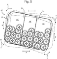
- An alternative counterbalance unit 42' with a plurality of internal cavities 48' to house vibration damping masses 52 is shown in Figure 5 .
- the volume of the cavity 48 (or cavities 48') of the housing 44 must be sufficient to accommodate the required number of masses 52, and allow them free movement within the cavity 48 (or cavities 48').
- the vibration damping masses 52 must be able to move (for example roll or vibrate) around the inside of the internal cavity 48 of the housing 44, that is to say, from side to side and/or up and down inside the internal cavity 48 or cavities 48' of the housing 44.
- the masses 38 must be able to move (for example roll and/or vibrate) at least part of the distance from one end/side of the internal cavity 48 to the other end/side of the internal cavity 48.
- the discrete masses 52 are arranged, and the cavity configured, such that the discrete masses are free to move and vibrate relative to one another in three dimensions.
- vibration damping counterbalance unit 42 Given the inherent lack of space in inceptor apparatus, and hence the need for the vibration damping counterbalance unit 42 to occupy a relatively small volume, generally a vibration mass material of high density is most appropriate. Additionally, it has been found that vibration damping masses of relatively small diameter are effective in damping out a wider range of frequencies. This is beneficial since vehicles, and in particular aircraft, are commonly subject to a broad range of vibrations.
- the inceptor apparatus 40 comprises a control stick 60 provided with the counterbalance unit 42, which may be removably fixed to the control stick 60.
- the counterbalance unit 42 may be attached to a control stick 60 by holes in flanges 66 provided on the housing 44.
- any means of attachment of the unit 42 to the control stick 60 may be used, for example by welding and/or other fixatives.
- the counterbalance unit 42 may be formed integrally with the stick member 60.
- FIG 6 there is shown a grip portion 62 of the control stick 60 fitted to one end of the control stick 60, and the vibration damping counterbalance unit 42 provided at the opposite end of the control stick 60.
- a pivot point 64 about which the control stick 60 may be pivoted. That is to say the control stick 60 is pivotably mounted about the pivot point 64 such that it may move in at least one of a first direction and second direction, the second direction being at right angles to the first direction.
- the first direction may be an "x" direction as shown in Figure 6 , or may be a "y” direction which is effectively in and out of the page as shown in Figure 6 , and represented as a dot. In this way, in use, the control stick may control an aircraft in pitch and roll directions.
- the vibration damping counterbalance unit 42 may be any appropriate shape. As shown in Figure 3 , the unit 42 has an irregular shape. However, the unit 42 may also be provided with a polygonal cross section, as shown Figure 4 onwards.
- the housing 44 may be manufactured from any appropriate material, but is preferably manufactured from stainless steel or a Tungsten alloy
- Figure 6 shows the control stick and counterbalance unit 42 in operation.
- the solid black lines define the structure of the device, and the dotted lines indicate positions which the control stick assembly may occupy during operation. That is to say, that the dotted lines indicate vibration, which may be from left to right as shown by arrow "A”, or may be up and down as shown in the figure as indicated by arrow “B”, or may be from side to side as shown by arrow "x" and point "y”, which indicates the direction at right angles to the direction as indicated by arrow "x".
- Figure 4 shows a cross sectional view which reveals the inside of the counterbalance unit 42 when vibrating as in Figures 6 , 7, 8 .
- the vibration damping masses 52 are shown vibrating up and down left and right and rotationally in the "x" and "y” directions.
- the dotted line surrounding the solid lines of the vibration damping masses 52 indicate the vibration being experienced by the vibration damping masses 52.
- the alternative unit 42' with internal partitions 54 shows how the vibration damping elements 52 may be arranged and vibrate in such an example of the present disclosure.
- the multiple masses 52 are free to move in all three axes under the effect of vibration, and hence provide vibration damping in all three axes. This creates a non-linear damping element.
- the discrete masses 52 When vibrated, the discrete masses 52 are free to react in a "random" nature they act to damp out the magnitude of the resonance induced by the input frequency. This reduction has a significant beneficial impact on the vibration amplitude magnification factor being applied to the mechanism.
- the vibration damping counterbalance unit 42 will also act to mass balance the stick 60 in a conventional manner.
- the vibration damping counterbalance unit of the present disclosure has particular efficacy when incorporated into an inceptor apparatus for an aircraft.
- the design of the present application can be applied to all inceptor designs where a counterbalance is required, and may be retrofitted to existing inceptors.
- the resulting reduction in response to vibration of the arrangement of the present disclosure has a significant and beneficial effect on component fatigue life, bearing wear and gearbox loading.
- This invention can be applied to all inceptor designs where a counterbalance is required.
Landscapes
- Engineering & Computer Science (AREA)
- Automation & Control Theory (AREA)
- Physics & Mathematics (AREA)
- General Physics & Mathematics (AREA)
- General Engineering & Computer Science (AREA)
- Mechanical Engineering (AREA)
- Aviation & Aerospace Engineering (AREA)
- Vibration Prevention Devices (AREA)
- Connection Of Motors, Electrical Generators, Mechanical Devices, And The Like (AREA)
Claims (14)
- Vibrationsdämpfende Gegengewichtseinheit für eine Steuerorganvorrichtung, wobei die Einheit dem Steuerorgan der Steuerorganvorrichtung als Gegengewicht dient und umfasst:eine Wand, die einen Hohlraum definiert; undeine Vielzahl von vibrationsdämpfenden Massen, die in dem Hohlraum untergebracht sind,wobei der Hohlraum so konfiguriert ist, dass die vibrationsdämpfenden Massen in Bezug auf die Hohlraumwand und relativ zueinander in jeder Richtung frei beweglich sind.
- Vibrationsdämpfende Gegengewichtseinheit nach Anspruch 1, wobei die vibrationsdämpfenden Massen im Wesentlichen kugelförmig sind.
- Vibrationsdämpfende Gegengewichtseinheit nach Anspruch 1 oder Anspruch 2, wobei die vibrationsdämpfenden Massen ein Metall umfassen, das eine Dichte von mindestens 15 g/cm3 aufweist.
- Vibrationsdämpfende Gegengewichtseinheit nach einem der vorhergehenden Ansprüche, wobei die vibrationsdämpfenden Massen eine Vickers-Härte von mindestens 2600 MPa aufweisen.
- Vibrationsdämpfende Gegengewichtseinheit nach einem der vorhergehenden Ansprüche, wobei die vibrationsdämpfenden Massen im Wesentlichen eine Wolframlegierung umfassen.
- Vibrationsdämpfende Gegengewichtseinheit nach einem der vorhergehenden Ansprüche, wobei die vibrationsdämpfenden Massen einen Durchmesser von mindestens 2,0 mm aber nicht mehr als ungefähr 5,0 mm aufweisen.
- Vibrationsdämpfende Gegengewichtseinheit nach einem der vorhergehenden Ansprüche, wobei der Durchmesser der vibrationsdämpfenden Massen eine Funktion ist von: erforderliche Gesamtgegengewichtsmasse; Dichte des Materials der vibrationsdämpfenden Masse; maximal erlaubte Hülle der vibrationsdämpfenden Gegengewichtseinheit; und erwünschtes freies Raumvolumen in dem Hohlraum.
- Vibrationsdämpfende Gegengewichtseinheit nach Anspruch 7, wobei das freie Raumvolumen in dem Hohlraum mindestens 15 % des Volumens des Hohlraums ausmacht.
- Vibrationsdämpfende Gegengewichtseinheit nach einem, der Ansprüche 1 bis 8, die nur einen Hohlraum umfasst, in dem die vibrationsdämpfenden Massen untergebracht sind.
- Vibrationsdämpfende Gegengewichtseinheit nach einem, der Ansprüche 1 bis 8, wobei der Hohlraum außerdem durch mindestens eine interne Trennwand definiert wird, um mindestens einen zusätzlichen Hohlraum zum Unterbringen von vibrationsdämpfenden Massen zu definieren.
- Steuerknüppel für eine Steuerorganvorrichtung, der mit einer vibrationsdämpfenden Gegengewichtseinheit nach einem der Ansprüche 1 bis 10 bereitgestellt wird.
- Steuerknüppel nach Anspruch 11, wobei die vibrationsdämpfende Gegengewichtseinheit abnehmbar an dem Steuerknüppel befestigt ist.
- Steuerorganvorrichtung die einen Steuerknüppel nach Anspruch 11 oder Anspruch 12 umfasst.
- Steuerorganvorrichtung nach Anspruch 13, wobei der Steuerknüppel so schwenkbar montiert ist, dass er in mindestens eine einer ersten Richtung und einer zweiten Richtung bewegt werden kann, wobei die zweite Richtung in einem rechten Winkel zur ersten Richtung steht.
Priority Applications (1)
| Application Number | Priority Date | Filing Date | Title |
|---|---|---|---|
| EP14736924.3A EP3016839B1 (de) | 2013-07-01 | 2014-06-27 | Gegengewichtseinheit eines steuerknüppel |
Applications Claiming Priority (4)
| Application Number | Priority Date | Filing Date | Title |
|---|---|---|---|
| EP20130275147 EP2821328A1 (de) | 2013-07-01 | 2013-07-01 | Gegengewichtseinheit eines Steuerknüppel |
| GB1311750.2A GB2515740A (en) | 2013-07-01 | 2013-07-01 | Counterbalance unit |
| PCT/GB2014/051968 WO2015001319A1 (en) | 2013-07-01 | 2014-06-27 | Counterbalance unit |
| EP14736924.3A EP3016839B1 (de) | 2013-07-01 | 2014-06-27 | Gegengewichtseinheit eines steuerknüppel |
Publications (2)
| Publication Number | Publication Date |
|---|---|
| EP3016839A1 EP3016839A1 (de) | 2016-05-11 |
| EP3016839B1 true EP3016839B1 (de) | 2018-04-25 |
Family
ID=51162843
Family Applications (1)
| Application Number | Title | Priority Date | Filing Date |
|---|---|---|---|
| EP14736924.3A Active EP3016839B1 (de) | 2013-07-01 | 2014-06-27 | Gegengewichtseinheit eines steuerknüppel |
Country Status (7)
| Country | Link |
|---|---|
| US (1) | US10114406B2 (de) |
| EP (1) | EP3016839B1 (de) |
| BR (1) | BR112015032872B1 (de) |
| CA (1) | CA2916935C (de) |
| ES (1) | ES2671321T3 (de) |
| TR (1) | TR201807303T4 (de) |
| WO (1) | WO2015001319A1 (de) |
Families Citing this family (3)
| Publication number | Priority date | Publication date | Assignee | Title |
|---|---|---|---|---|
| ES2671321T3 (es) | 2013-07-01 | 2018-06-06 | Bae Systems Plc | Unidad de equilibrado |
| CA2916961C (en) | 2013-07-01 | 2021-08-31 | Bae Systems Plc | Inceptor and method for operating an inceptor |
| US10118688B2 (en) * | 2015-08-18 | 2018-11-06 | Woodward, Inc. | Inherently balanced control stick |
Citations (1)
| Publication number | Priority date | Publication date | Assignee | Title |
|---|---|---|---|---|
| US3990535A (en) * | 1975-09-11 | 1976-11-09 | Bruce Jimmie R | Vibration damping device for levers |
Family Cites Families (16)
| Publication number | Priority date | Publication date | Assignee | Title |
|---|---|---|---|---|
| DE2530802A1 (de) * | 1975-07-10 | 1977-01-27 | Volkswagenwerk Ag | Schalthebellagerung |
| US4689449A (en) * | 1986-10-03 | 1987-08-25 | Massachusetts Institute Of Technology | Tremor suppressing hand controls |
| SU1456654A1 (ru) | 1986-11-28 | 1989-02-07 | Волгоградский Политехнический Институт | Устройство дл гашени вибраций |
| SU1428873A2 (ru) | 1986-12-29 | 1988-10-07 | Куйбышевский политехнический институт им.В.В.Куйбышева | Устройство дл гашени вибрации |
| JPH03193531A (ja) | 1989-12-22 | 1991-08-23 | Nissan Motor Co Ltd | 車両用変速装置 |
| US5027715A (en) * | 1990-02-12 | 1991-07-02 | Mid-West Conveyor Company, Inc. | Shock absorbing carrier |
| WO1996038810A1 (de) | 1995-06-02 | 1996-12-05 | Gerhard Wergen | Analoges stellelement |
| GB9926199D0 (en) * | 1999-11-05 | 2000-01-12 | Rolls Royce Plc | A particle vibration damper for a non-rotating component of a gas turbine engine |
| GB0105356D0 (en) * | 2001-03-03 | 2001-04-18 | Rolls Royce Plc | Friction vibration damper |
| TW490787B (en) * | 2001-07-10 | 2002-06-11 | Asm Assembly Automation Ltd | High speed pick and place apparatus |
| ATE501476T1 (de) * | 2006-05-12 | 2011-03-15 | Bae Systems Plc | Verbesserungen in bezug auf eine aktiv-stick- vorrichtung |
| JP5244018B2 (ja) * | 2009-04-09 | 2013-07-24 | 株式会社神戸製鋼所 | 制振構造 |
| US8991574B2 (en) * | 2009-06-19 | 2015-03-31 | Toyota Motor Engineering & Manufacturing North America, Inc. | Apparatus for reducing vibrations in a vehicle |
| JP4802277B2 (ja) * | 2009-12-28 | 2011-10-26 | ナカシマメディカル株式会社 | 衝撃吸収構造体及びその製造方法 |
| CA2916961C (en) | 2013-07-01 | 2021-08-31 | Bae Systems Plc | Inceptor and method for operating an inceptor |
| ES2671321T3 (es) | 2013-07-01 | 2018-06-06 | Bae Systems Plc | Unidad de equilibrado |
-
2014
- 2014-06-27 ES ES14736924.3T patent/ES2671321T3/es active Active
- 2014-06-27 US US14/901,750 patent/US10114406B2/en active Active
- 2014-06-27 TR TR2018/07303T patent/TR201807303T4/tr unknown
- 2014-06-27 WO PCT/GB2014/051968 patent/WO2015001319A1/en not_active Ceased
- 2014-06-27 CA CA2916935A patent/CA2916935C/en active Active
- 2014-06-27 EP EP14736924.3A patent/EP3016839B1/de active Active
- 2014-06-27 BR BR112015032872-5A patent/BR112015032872B1/pt active IP Right Grant
Patent Citations (1)
| Publication number | Priority date | Publication date | Assignee | Title |
|---|---|---|---|---|
| US3990535A (en) * | 1975-09-11 | 1976-11-09 | Bruce Jimmie R | Vibration damping device for levers |
Also Published As
| Publication number | Publication date |
|---|---|
| BR112015032872A2 (pt) | 2020-05-12 |
| US20160357216A1 (en) | 2016-12-08 |
| ES2671321T3 (es) | 2018-06-06 |
| CA2916935C (en) | 2021-05-25 |
| BR112015032872B1 (pt) | 2022-08-02 |
| EP3016839A1 (de) | 2016-05-11 |
| US10114406B2 (en) | 2018-10-30 |
| WO2015001319A1 (en) | 2015-01-08 |
| TR201807303T4 (tr) | 2018-06-21 |
| CA2916935A1 (en) | 2015-01-08 |
Similar Documents
| Publication | Publication Date | Title |
|---|---|---|
| EP3016839B1 (de) | Gegengewichtseinheit eines steuerknüppel | |
| US20070144842A1 (en) | Vibration control system | |
| DE112013002833T5 (de) | Aktives Schwingungsisolationssystem | |
| US8101924B2 (en) | Object-positioning device for charged-particle beam system | |
| US20160032548A1 (en) | Soil Compacting Device Having Spring Suspension and Guiding | |
| DE102013205230B3 (de) | Schwingungsdämpfer für Abschirmblech | |
| US7862056B2 (en) | Steering gear inertia damper | |
| CN108087473A (zh) | 一种气液弹双频隔振器 | |
| JP2012101650A (ja) | キャスター | |
| US8960386B2 (en) | Damping arrangement | |
| EP2821328A1 (de) | Gegengewichtseinheit eines Steuerknüppel | |
| KR101416518B1 (ko) | 항공기 동력 전달 기어박스의 타이 바에 관한 진동 방지 현가 수단, 진동 방지 현가 장치, 및 항공기 | |
| CN112567096A (zh) | 用于单偏心压实机滚筒的方向性振动控制设备 | |
| KR20160067064A (ko) | 방진지지유닛과 이를 이용한 진동리퍼 | |
| GB2515740A (en) | Counterbalance unit | |
| KR100881087B1 (ko) | 차량 자세 안정화 장치 | |
| CN113165693B (zh) | 用于衰减振动的可调动态吸收器 | |
| CH562617A5 (en) | Ski with vibration damping device - uses spring loaded ball in oil filled cylinder to absorb vibration energy | |
| JP6312612B2 (ja) | 動吸振器 | |
| US6119834A (en) | Vibration damping device | |
| JP2772410B2 (ja) | ヘリコプタの能動防振装置 | |
| JP2006104725A (ja) | ランマのハンドル用防振構造 | |
| JP2010221766A (ja) | 航空機脚 | |
| JP2005201293A (ja) | 防振器およびその調整方法 | |
| KR101807968B1 (ko) | 복합형 진동 저감 장치 |
Legal Events
| Date | Code | Title | Description |
|---|---|---|---|
| PUAI | Public reference made under article 153(3) epc to a published international application that has entered the european phase |
Free format text: ORIGINAL CODE: 0009012 |
|
| 17P | Request for examination filed |
Effective date: 20160121 |
|
| AK | Designated contracting states |
Kind code of ref document: A1 Designated state(s): AL AT BE BG CH CY CZ DE DK EE ES FI FR GB GR HR HU IE IS IT LI LT LU LV MC MK MT NL NO PL PT RO RS SE SI SK SM TR |
|
| AX | Request for extension of the european patent |
Extension state: BA ME |
|
| DAX | Request for extension of the european patent (deleted) | ||
| RIC1 | Information provided on ipc code assigned before grant |
Ipc: G05G 25/02 20060101ALI20171004BHEP Ipc: G05G 9/047 20060101ALI20171004BHEP Ipc: B64C 13/10 20060101ALI20171004BHEP Ipc: B64C 19/00 20060101ALI20171004BHEP Ipc: B62D 27/00 20060101AFI20171004BHEP Ipc: F16F 7/01 20060101ALI20171004BHEP |
|
| GRAP | Despatch of communication of intention to grant a patent |
Free format text: ORIGINAL CODE: EPIDOSNIGR1 |
|
| INTG | Intention to grant announced |
Effective date: 20171201 |
|
| GRAA | (expected) grant |
Free format text: ORIGINAL CODE: 0009210 |
|
| GRAS | Grant fee paid |
Free format text: ORIGINAL CODE: EPIDOSNIGR3 |
|
| AK | Designated contracting states |
Kind code of ref document: B1 Designated state(s): AL AT BE BG CH CY CZ DE DK EE ES FI FR GB GR HR HU IE IS IT LI LT LU LV MC MK MT NL NO PL PT RO RS SE SI SK SM TR |
|
| REG | Reference to a national code |
Ref country code: GB Ref legal event code: FG4D |
|
| REG | Reference to a national code |
Ref country code: CH Ref legal event code: EP |
|
| REG | Reference to a national code |
Ref country code: AT Ref legal event code: REF Ref document number: 992570 Country of ref document: AT Kind code of ref document: T Effective date: 20180515 |
|
| REG | Reference to a national code |
Ref country code: IE Ref legal event code: FG4D |
|
| REG | Reference to a national code |
Ref country code: DE Ref legal event code: R096 Ref document number: 602014024465 Country of ref document: DE |
|
| REG | Reference to a national code |
Ref country code: ES Ref legal event code: FG2A Ref document number: 2671321 Country of ref document: ES Kind code of ref document: T3 Effective date: 20180606 |
|
| REG | Reference to a national code |
Ref country code: FR Ref legal event code: PLFP Year of fee payment: 5 |
|
| REG | Reference to a national code |
Ref country code: NL Ref legal event code: MP Effective date: 20180425 |
|
| REG | Reference to a national code |
Ref country code: LT Ref legal event code: MG4D |
|
| PG25 | Lapsed in a contracting state [announced via postgrant information from national office to epo] |
Ref country code: NL Free format text: LAPSE BECAUSE OF FAILURE TO SUBMIT A TRANSLATION OF THE DESCRIPTION OR TO PAY THE FEE WITHIN THE PRESCRIBED TIME-LIMIT Effective date: 20180425 |
|
| PG25 | Lapsed in a contracting state [announced via postgrant information from national office to epo] |
Ref country code: NO Free format text: LAPSE BECAUSE OF FAILURE TO SUBMIT A TRANSLATION OF THE DESCRIPTION OR TO PAY THE FEE WITHIN THE PRESCRIBED TIME-LIMIT Effective date: 20180725 Ref country code: FI Free format text: LAPSE BECAUSE OF FAILURE TO SUBMIT A TRANSLATION OF THE DESCRIPTION OR TO PAY THE FEE WITHIN THE PRESCRIBED TIME-LIMIT Effective date: 20180425 Ref country code: BG Free format text: LAPSE BECAUSE OF FAILURE TO SUBMIT A TRANSLATION OF THE DESCRIPTION OR TO PAY THE FEE WITHIN THE PRESCRIBED TIME-LIMIT Effective date: 20180725 Ref country code: PL Free format text: LAPSE BECAUSE OF FAILURE TO SUBMIT A TRANSLATION OF THE DESCRIPTION OR TO PAY THE FEE WITHIN THE PRESCRIBED TIME-LIMIT Effective date: 20180425 Ref country code: SE Free format text: LAPSE BECAUSE OF FAILURE TO SUBMIT A TRANSLATION OF THE DESCRIPTION OR TO PAY THE FEE WITHIN THE PRESCRIBED TIME-LIMIT Effective date: 20180425 Ref country code: LT Free format text: LAPSE BECAUSE OF FAILURE TO SUBMIT A TRANSLATION OF THE DESCRIPTION OR TO PAY THE FEE WITHIN THE PRESCRIBED TIME-LIMIT Effective date: 20180425 |
|
| PG25 | Lapsed in a contracting state [announced via postgrant information from national office to epo] |
Ref country code: LV Free format text: LAPSE BECAUSE OF FAILURE TO SUBMIT A TRANSLATION OF THE DESCRIPTION OR TO PAY THE FEE WITHIN THE PRESCRIBED TIME-LIMIT Effective date: 20180425 Ref country code: HR Free format text: LAPSE BECAUSE OF FAILURE TO SUBMIT A TRANSLATION OF THE DESCRIPTION OR TO PAY THE FEE WITHIN THE PRESCRIBED TIME-LIMIT Effective date: 20180425 Ref country code: GR Free format text: LAPSE BECAUSE OF FAILURE TO SUBMIT A TRANSLATION OF THE DESCRIPTION OR TO PAY THE FEE WITHIN THE PRESCRIBED TIME-LIMIT Effective date: 20180726 Ref country code: RS Free format text: LAPSE BECAUSE OF FAILURE TO SUBMIT A TRANSLATION OF THE DESCRIPTION OR TO PAY THE FEE WITHIN THE PRESCRIBED TIME-LIMIT Effective date: 20180425 |
|
| REG | Reference to a national code |
Ref country code: AT Ref legal event code: MK05 Ref document number: 992570 Country of ref document: AT Kind code of ref document: T Effective date: 20180425 |
|
| PG25 | Lapsed in a contracting state [announced via postgrant information from national office to epo] |
Ref country code: PT Free format text: LAPSE BECAUSE OF FAILURE TO SUBMIT A TRANSLATION OF THE DESCRIPTION OR TO PAY THE FEE WITHIN THE PRESCRIBED TIME-LIMIT Effective date: 20180827 |
|
| REG | Reference to a national code |
Ref country code: DE Ref legal event code: R097 Ref document number: 602014024465 Country of ref document: DE |
|
| PG25 | Lapsed in a contracting state [announced via postgrant information from national office to epo] |
Ref country code: DK Free format text: LAPSE BECAUSE OF FAILURE TO SUBMIT A TRANSLATION OF THE DESCRIPTION OR TO PAY THE FEE WITHIN THE PRESCRIBED TIME-LIMIT Effective date: 20180425 Ref country code: AT Free format text: LAPSE BECAUSE OF FAILURE TO SUBMIT A TRANSLATION OF THE DESCRIPTION OR TO PAY THE FEE WITHIN THE PRESCRIBED TIME-LIMIT Effective date: 20180425 Ref country code: EE Free format text: LAPSE BECAUSE OF FAILURE TO SUBMIT A TRANSLATION OF THE DESCRIPTION OR TO PAY THE FEE WITHIN THE PRESCRIBED TIME-LIMIT Effective date: 20180425 Ref country code: CZ Free format text: LAPSE BECAUSE OF FAILURE TO SUBMIT A TRANSLATION OF THE DESCRIPTION OR TO PAY THE FEE WITHIN THE PRESCRIBED TIME-LIMIT Effective date: 20180425 Ref country code: RO Free format text: LAPSE BECAUSE OF FAILURE TO SUBMIT A TRANSLATION OF THE DESCRIPTION OR TO PAY THE FEE WITHIN THE PRESCRIBED TIME-LIMIT Effective date: 20180425 Ref country code: SK Free format text: LAPSE BECAUSE OF FAILURE TO SUBMIT A TRANSLATION OF THE DESCRIPTION OR TO PAY THE FEE WITHIN THE PRESCRIBED TIME-LIMIT Effective date: 20180425 |
|
| REG | Reference to a national code |
Ref country code: CH Ref legal event code: PL |
|
| PG25 | Lapsed in a contracting state [announced via postgrant information from national office to epo] |
Ref country code: SM Free format text: LAPSE BECAUSE OF FAILURE TO SUBMIT A TRANSLATION OF THE DESCRIPTION OR TO PAY THE FEE WITHIN THE PRESCRIBED TIME-LIMIT Effective date: 20180425 |
|
| PLBE | No opposition filed within time limit |
Free format text: ORIGINAL CODE: 0009261 |
|
| STAA | Information on the status of an ep patent application or granted ep patent |
Free format text: STATUS: NO OPPOSITION FILED WITHIN TIME LIMIT |
|
| REG | Reference to a national code |
Ref country code: BE Ref legal event code: MM Effective date: 20180630 |
|
| PG25 | Lapsed in a contracting state [announced via postgrant information from national office to epo] |
Ref country code: LU Free format text: LAPSE BECAUSE OF NON-PAYMENT OF DUE FEES Effective date: 20180627 Ref country code: MC Free format text: LAPSE BECAUSE OF FAILURE TO SUBMIT A TRANSLATION OF THE DESCRIPTION OR TO PAY THE FEE WITHIN THE PRESCRIBED TIME-LIMIT Effective date: 20180425 |
|
| 26N | No opposition filed |
Effective date: 20190128 |
|
| REG | Reference to a national code |
Ref country code: IE Ref legal event code: MM4A |
|
| PG25 | Lapsed in a contracting state [announced via postgrant information from national office to epo] |
Ref country code: CH Free format text: LAPSE BECAUSE OF NON-PAYMENT OF DUE FEES Effective date: 20180630 Ref country code: IE Free format text: LAPSE BECAUSE OF NON-PAYMENT OF DUE FEES Effective date: 20180627 Ref country code: LI Free format text: LAPSE BECAUSE OF NON-PAYMENT OF DUE FEES Effective date: 20180630 |
|
| PG25 | Lapsed in a contracting state [announced via postgrant information from national office to epo] |
Ref country code: SI Free format text: LAPSE BECAUSE OF FAILURE TO SUBMIT A TRANSLATION OF THE DESCRIPTION OR TO PAY THE FEE WITHIN THE PRESCRIBED TIME-LIMIT Effective date: 20180425 Ref country code: BE Free format text: LAPSE BECAUSE OF NON-PAYMENT OF DUE FEES Effective date: 20180630 |
|
| PG25 | Lapsed in a contracting state [announced via postgrant information from national office to epo] |
Ref country code: AL Free format text: LAPSE BECAUSE OF FAILURE TO SUBMIT A TRANSLATION OF THE DESCRIPTION OR TO PAY THE FEE WITHIN THE PRESCRIBED TIME-LIMIT Effective date: 20180425 |
|
| PG25 | Lapsed in a contracting state [announced via postgrant information from national office to epo] |
Ref country code: MT Free format text: LAPSE BECAUSE OF NON-PAYMENT OF DUE FEES Effective date: 20180627 |
|
| PG25 | Lapsed in a contracting state [announced via postgrant information from national office to epo] |
Ref country code: MK Free format text: LAPSE BECAUSE OF NON-PAYMENT OF DUE FEES Effective date: 20180425 Ref country code: HU Free format text: LAPSE BECAUSE OF FAILURE TO SUBMIT A TRANSLATION OF THE DESCRIPTION OR TO PAY THE FEE WITHIN THE PRESCRIBED TIME-LIMIT; INVALID AB INITIO Effective date: 20140627 Ref country code: CY Free format text: LAPSE BECAUSE OF FAILURE TO SUBMIT A TRANSLATION OF THE DESCRIPTION OR TO PAY THE FEE WITHIN THE PRESCRIBED TIME-LIMIT Effective date: 20180425 |
|
| PG25 | Lapsed in a contracting state [announced via postgrant information from national office to epo] |
Ref country code: IS Free format text: LAPSE BECAUSE OF FAILURE TO SUBMIT A TRANSLATION OF THE DESCRIPTION OR TO PAY THE FEE WITHIN THE PRESCRIBED TIME-LIMIT Effective date: 20180825 |
|
| PGFP | Annual fee paid to national office [announced via postgrant information from national office to epo] |
Ref country code: DE Payment date: 20250520 Year of fee payment: 12 |
|
| PGFP | Annual fee paid to national office [announced via postgrant information from national office to epo] |
Ref country code: GB Payment date: 20250520 Year of fee payment: 12 |
|
| PGFP | Annual fee paid to national office [announced via postgrant information from national office to epo] |
Ref country code: IT Payment date: 20250520 Year of fee payment: 12 |
|
| PGFP | Annual fee paid to national office [announced via postgrant information from national office to epo] |
Ref country code: FR Payment date: 20250520 Year of fee payment: 12 |
|
| PGFP | Annual fee paid to national office [announced via postgrant information from national office to epo] |
Ref country code: TR Payment date: 20250530 Year of fee payment: 12 |
|
| PGFP | Annual fee paid to national office [announced via postgrant information from national office to epo] |
Ref country code: ES Payment date: 20250701 Year of fee payment: 12 |