EP3016846B1 - Elektrische hilfsantriebsvorrichtung für fahrräder und fahrrad mit dieser vorrichtung - Google Patents
Elektrische hilfsantriebsvorrichtung für fahrräder und fahrrad mit dieser vorrichtung Download PDFInfo
- Publication number
- EP3016846B1 EP3016846B1 EP14739725.1A EP14739725A EP3016846B1 EP 3016846 B1 EP3016846 B1 EP 3016846B1 EP 14739725 A EP14739725 A EP 14739725A EP 3016846 B1 EP3016846 B1 EP 3016846B1
- Authority
- EP
- European Patent Office
- Prior art keywords
- electric power
- sub
- assembly
- supporting structure
- assist device
- Prior art date
- Legal status (The legal status is an assumption and is not a legal conclusion. Google has not performed a legal analysis and makes no representation as to the accuracy of the status listed.)
- Active
Links
Images


Classifications
-
- B—PERFORMING OPERATIONS; TRANSPORTING
- B62—LAND VEHICLES FOR TRAVELLING OTHERWISE THAN ON RAILS
- B62M—RIDER PROPULSION OF WHEELED VEHICLES OR SLEDGES; POWERED PROPULSION OF SLEDGES OR SINGLE-TRACK CYCLES; TRANSMISSIONS SPECIALLY ADAPTED FOR SUCH VEHICLES
- B62M6/00—Rider propulsion of wheeled vehicles with additional source of power, e.g. combustion engine or electric motor
- B62M6/40—Rider propelled cycles with auxiliary electric motor
- B62M6/75—Rider propelled cycles with auxiliary electric motor power-driven by friction rollers or gears engaging the ground wheel
-
- B—PERFORMING OPERATIONS; TRANSPORTING
- B62—LAND VEHICLES FOR TRAVELLING OTHERWISE THAN ON RAILS
- B62M—RIDER PROPULSION OF WHEELED VEHICLES OR SLEDGES; POWERED PROPULSION OF SLEDGES OR SINGLE-TRACK CYCLES; TRANSMISSIONS SPECIALLY ADAPTED FOR SUCH VEHICLES
- B62M6/00—Rider propulsion of wheeled vehicles with additional source of power, e.g. combustion engine or electric motor
- B62M6/80—Accessories, e.g. power sources; Arrangements thereof
- B62M6/90—Batteries
-
- H—ELECTRICITY
- H02—GENERATION; CONVERSION OR DISTRIBUTION OF ELECTRIC POWER
- H02K—DYNAMO-ELECTRIC MACHINES
- H02K5/00—Casings; Enclosures; Supports
- H02K5/04—Casings or enclosures characterised by the shape, form or construction thereof
-
- H—ELECTRICITY
- H02—GENERATION; CONVERSION OR DISTRIBUTION OF ELECTRIC POWER
- H02K—DYNAMO-ELECTRIC MACHINES
- H02K7/00—Arrangements for handling mechanical energy structurally associated with dynamo-electric machines, e.g. structural association with mechanical driving motors or auxiliary dynamo-electric machines
- H02K7/10—Structural association with clutches, brakes, gears, pulleys or mechanical starters
- H02K7/116—Structural association with clutches, brakes, gears, pulleys or mechanical starters with gears
Definitions
- the present invention relates to electrical assistance devices for bicycles and bicycles equipped with such devices.
- Some of these devices use an electric machine placed in the hub of one of the wheels of the bicycle. This electric machine drives the wheel directly or through a reduction system. This type of device has the disadvantage of a large mass, this mass also being located at the level of the wheel, which makes it very sensitive for the cyclist. In addition, when the wheel has to be removed, for example to change the tire or repair a puncture, removing the wheel is made complex by the presence of electrical connections which are necessary to supply the electrical machine and specific hub fasteners that are necessary to recover the engine torque.
- the document DE-20314210-U1 describes a principle of driving a bicycle by an electric motor in which a motor pinion meshes on a toothing integral with the circle of the front rim of the bicycle, said toothing being an internal toothing, that is to say whose teeth point towards the wheel axle.
- a drawback of this system is that the teeth on the rim are liable to retain stones.
- the document describes an electric assistance device for a bicycle which comprises means for fixing the device carried by the frame.
- the drive of the bicycle wheel is done either, as in the previous document, at a level of teeth integral with the circle of the rim of the bicycle, or by friction at the level of the tread.
- the object of the invention is therefore to propose an electric assistance device for a bicycle as well as a bicycle equipped with said device which solve all or part of these difficulties.
- the invention therefore provides an electrical assistance device for a bicycle according to claim 1.
- means for controlling the electric machine are also carried by the frame.
- the electric assistance device further comprises a battery for supplying the electric machine, the battery also being carried by the frame.
- the manually separable sub-assembly of the frame comprises the means for controlling the electric machine.
- the manually separable sub-assembly of the frame further comprises the battery.
- the battery is also manually separable from the frame independently of the sub-assembly.
- the sub-assembly is carried by a frame extending in a substantially horizontal plane, said sub-assembly being separable horizontally from the frame, preferably, preferably transversely.
- the frame comprises a quick electrical connector for connecting the sub-assembly to interfaces integral with the bicycle.
- the frame also constitutes a luggage rack.
- the fixing means comprise an oscillating arm articulated with respect to a base carried by the frame along an axis substantially parallel to the axis of the electric machine.
- the swinging arm includes an articulation making it possible to fold the electric machine against the sub-assembly.
- the invention also relates to an electric assistance kit for a bicycle comprising the electric assistance device described above, said electric assistance kit further comprising a tire, said tire being a pneumatic tire having said complementary toothing.
- the invention relates to an electrically assisted bicycle comprising such an electric assistance kit.
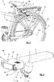
- An electric machine 2 is fixed near a tire 5, here near the tire of the rear wheel 61.
- a drive pinion 3 meshes tangentially with a toothing 51 secured to the tire 5 and can thus transmit to it a driving force which assists the cyclist.
- the electric machine is preferably a three-phase synchronous brushless motor with permanent magnets. More preferably, the rotor is an external rotor as shown in the figures.
- a battery 7 supplies the electric machine.
- the fixing means 4 of the electric machine are carried by a frame 10, itself fixed to the frame 11 of the bicycle.
- Arms 101, 102, 103, 104 of the frame are preferably fixed on the axis of the wheel 612.
- Tie rods 116 immobilize the rotation of the frame around the axis of the wheel. Attaching the frame to the wheel axle allows mounting simple while ensuring high precision and reproducibility of the positioning of the drive pinion 3 relative to the teeth 51 of the tire.
- the battery is also carried by the frame as shown here.
- the battery can be attached to another part of the bicycle in a manner known per se.
- control means 8 of the electric machine that is to say the control electronics and the power electronics, are also carried by the frame.
- a separable sub-assembly 20 is made up of the fixing means and the electric machine. This sub-assembly is manually separable from the frame, that is to say without the aid of any tool.
- the sub-assembly 20 further comprises the control means 8.
- the separable sub-assembly may also include said battery as shown in the figure 2 . It is understood that the fact of removing such a sub-assembly 20 from the frame makes it possible to use the bicycle without electrical assistance but also without the overweight associated with electrical assistance and its source of energy.
- control means 8 include a switch 81 allowing the cyclist to turn on or off the assistance device and a rotary button 82 for adjusting the assistance level. These commands can also be placed on the handlebars of the bicycle or controlled remotely via a remote control or an application installed in a mobile phone of the cyclist. An electrical power outlet 21 for recharging the battery is accessible even when the sub-assembly is mounted in the frame.
- the figure 3 shows this subset 20 in bottom view.
- the fastening means 4 of the electric machine preferably comprise an oscillating arm 41 and a base 42, the base being intended to be integral with the frame and the oscillating arm 41 being articulated relative to the base according to an axis of oscillation 43 substantially parallel to the axis 21 of the electric machine.
- a spring 44 constrains the arm so that the pinion is applied with a certain force minimal support against the bandage.
- a quick electrical connector 106 and a notch 107 for the key locking means.
- the engine block 22 therefore comprises in particular the base 42, the oscillating arm 41, the electric machine 2 and preferably also the electronic power and control circuits. It is understood that it is this engine block which must be firmly secured to the frame when the electric assistance device is used. Fins 25 may be provided on one or more of the faces of the engine block 22 (see figure 2 ) in order to improve the cooling of the power electronics located inside the engine block 22 in contact with the face or faces provided with fins 25. This cooling principle is particularly effective in the case where the engine block or the fins are made of a material which is a good thermal conductor such as aluminum.
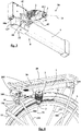
- the frame 10 carrying the separable sub-assembly 20 has a frame 105 extending in a substantially horizontal plane.
- the sub-assembly 20 can be slid horizontally into the frame and be fixed there by a quick coupler 108 at the front of the latter.
- the rear end of the sub-assembly 20 (constituted by the rear part of the battery) is locked in the frame by a fixed stop 109.
- the sub-assembly 20 is extracted and we see a stationary electrical connector 110 capable of cooperating with the connector 106 of the sub-assembly.
- the stationary connector 110 can be used to connect the electrical assistance device to interfaces or sensors installed on the bicycle.
- a handlebar control interface may be provided for access to information and / or for control of the device by the cyclist.
- sensors which may be useful for controlling the electrical assistance device, let us quote for example the pedaling sensors, pedaling torque sensor, speed sensor.
- the connector can also be used to power the bicycle lighting from the battery 7.
- locking means 111 as well as the quick coupler 108.
- the installation of the sub-assembly 20 consists in placing the end of the battery in position behind the fixed stop 109 and then pivoting in a horizontal plane the front of the sub-assembly 20 until it is possible to engage the quick coupler 108.
- the stationary connector 110 is well associated with the connector 106 of the sub-assembly and the locking means 111 (for example with key) can be actuated and cooperate with the notch 107 of the sub-assembly. together (visible on the figure 3 ) to secure it if necessary in the position of use.
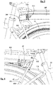
- the figure 6 shows from the other side of the bike, the same sub-assembly installed in the frame. We see in particular the barrel 112 of the key lock.
- the figure 7 shows the device when the battery is in place and the figure 8 shows the device when the battery alone is removed. It is understood that the battery is extracted horizontally from the frame in a longitudinal rearward movement.
- the figure 9 shows in particular the transverse ribs 114 of the frame 105 which cooperate with transverse grooves 23 of the engine block.
- This arrangement makes it possible to guide the sub-assembly during its installation in the frame and ensures rigid and reliable maintenance of the base 42 and therefore of the means for fixing the electric machine 2.
- the sub- together must therefore be extracted horizontally and in a transverse movement.
- the battery can remain integral with the engine block (as shown in the figure 7 ) and therefore follow the same movement.
- the battery may also have been previously removed from the rear of the frame as shown in the figure 8 .
- FIG 10 we see from a different angle the same sub-assembly in place in the frame without the battery.
- This view shows the locking means 111 which are adapted to the different situations and handling described above.
- the sector of the locking means 111 comprises a curved groove 113 intended to cooperate with a finger 71 of the battery (see figure 11 ) to selectively block it in place or allow its extraction according to the angular position of the sector.
- the locking means comprise a third position making it possible to release and therefore to extract the complete sub-assembly (or the engine block in the case where the battery has already been extracted).
- the position shown in figure 9 is the one that allows the extraction of the battery while keeping the engine block locked.
- cooling fins 411 coming from the swinging arm 41 we also see cooling fins 411 coming from the swinging arm 41. These fins favor the cooling of the stator of the electric machine by ambient air since the internal stator of the electric machine is integral with arm 41 (see also figure 3 ).
- the battery comprises an elastic button 74 intended to cooperate with an opening 24 of the sub-assembly (see figure 10 ) to ensure a quick and safe connection (by clipping) of the battery 7 to the engine block 22, including in the absence of locking.
- the battery also has two contacts 72 and 73 for its electrical connection to the engine block, as well as a socket for recharging 21.
- the figure 12 shows the complete sub-assembly 20 according to a variant of this embodiment in which the engine block also comprises an elastic button 115 similar to the elastic button 74 of the battery.
- the elastic button 115 is intended to cooperate with an opening made on the front face of the frame 105 in order to ensure a quick and secure connection (by clipping) of the engine block 22 to the frame, including in the absence of locking.
- the angle ⁇ can vary but it is preferably between - 10 ° and + 30 °.
- ⁇ is approximately 25 °
- the toothing 51 is integral with a sidewall 52 of the tire and is located radially under the equator 54.
- the tire can be a pneumatic or non-pneumatic tire, or even a solid tire.
- the electric machine directly drives the motor pinion, that is to say without any intermediate reduction means, the pinion being carried by the shaft of the electric machine.
- a freewheel mechanism is however interposed between the shaft and the pinion so that the tire does not drive the electric machine when the bicycle is moving in forward gear. In the event that the device does not include a freewheel, an electrical energy recovery can be carried out when the cyclist brakes.
- the electric machine 2 is preferably placed radially outside the drive pinion 3 with respect to the axis 612 of the bicycle wheel, that is to say above the drive pinion 3 in this configuration.
- the figure 14 shows in detail the meshing of the drive pinion 3 on the tire.
- the pinion transmits an FM motive force to the bandage.
- the teeth 32 of the pinion are asymmetrical and configured so that the opening angle of their driving faces 33 is smaller than the opening angle of their non-driving faces 34
- the shape of the complementary toothing 51 secured to the bandage is naturally adapted accordingly. This arrangement makes it possible to significantly improve the efficiency of the meshing as well as to increase the maximum value of the transmissible FM driving force.
- Line D1 is the line perpendicular to the tangent of the teeth at the point of contact halfway up the teeth (see also figure 16 ).
- the half-lines D2 and D3 are separated from D1 by an angle ⁇ .
- Sector A corresponds to the area between line D1 and half-line D2.
- Sector B corresponds to the area between the line D1 and the half-line D3.
- the angle y does not exceed 60 °.
- the intersection must be located in sector A shown in figure 14 .
- the teeth 31 of the pinion 3 have been shown on a larger scale in order to better visualize the preferred asymmetrical embodiment described in figure 12 . It can be seen that the opening angle A1 of the driving faces 33 is substantially smaller than the opening angle A2 of the non-driving faces 34.
- the teeth 51 of the bandage have been shown on a larger scale in order to better visualize a preferred embodiment.
- the teeth 511 of the toothing of the tire have drive faces 512 and non-drive faces 513.
- the opening angle B1 of the drive faces 512 is significantly smaller than the opening angle B2 of the non-driving faces 513.
- the teeth have a pitch P and a height H.
- the pitch of the teeth is preferably between 1.8 mm and 5.5 mm.
- the straight line D1 mentioned above with reference to the figure 14 is also shown in this figure.
- FIGS. 15 and 16 illustrate teeth with rectilinear faces.
- the angles described above must be measured by considering the tangent at the point of the profile corresponding to the half-height of the tooth (see the mean radius Rm on the figure 15 and the half height H / 2 on the figure 16 ).
- the toothing is a helical toothing similar to those visible on the Figures 1 to 12 .
- the axis of the teeth 32 is inclined at an angle ⁇ relative to the axis 35 of the pinion and therefore relative to the shaft of the electric machine 21.
- the angle ⁇ shown here is approximately 15 °, but it can for example be between 4 and 40 ° and preferably between 10 and 30 °.
- the inclination of the toothing of the bandage must naturally be adapted accordingly. This arrangement significantly reduces the noise emitted by the meshing.
- the drive pinion 3 is made of metal, for example in steel. If necessary, the freewheel mentioned above can be integrated inside the pinion.
- FIG 18 a preferred embodiment of the tire 5 is seen.
- This is a pneumatic tire comprising, in a manner known per se, sidewalls 52, a tread 53 and rods 54 for its anchoring on a non-bicycle rim. represented. It can also be seen that the teeth of the toothing 51 secured to the side are inclined relative to the radial direction of the tire by an angle corresponding to the helix angle ⁇ described for the drive pinion with reference to the figure 17 .
- the toothing of the tire consists mainly of rubber with a Shore A hardness preferably between 55 and 85.
- the toothing is preferably molded at the same time as the tire, but it can also be applied to a conventional molded tire. previously.
- a textile reinforcement can be associated with the surface of the toothing in order to limit wear by abrasion and the noise of toothing. It is advantageous to use textile reinforcement fabrics of the polyamide type, woven so as to be extensible during the molding of the teeth.
- the toothing 51 is placed radially under the equator 54 of the tire 5.
- the toothing can be placed at the shoulder of the tire, that is to say near the tread 53, or even in the center of the tread bearing 53, in horizontal position.
- a third embodiment of the electric assistance device according to the invention is shown in which the axis 43 of oscillation of the arm is located at the rear of the pinion relative to the direction of advance of the bicycle.
- the angle ⁇ is approximately 5 ° and the angle ⁇ is approximately 24 °. Note that these angles are also quite applicable in the configurations of the previous figures.
- the arm 41 here comprises an articulation along a fold axis 45.
- This articulation allows the electric machine to fold against the base when the assistance is not implemented.
- the fallback operation of the electric machine can be done by means of an actuator of preferably electrically or manually by rotation of the oscillating half-arm 41b relative to the oscillating half-arm 41a about the fold-back axis 45 which is here substantially parallel to the direction of advance of the bicycle.
- the return to the operating position is done in reverse by withdrawing the electric machine in rotation about the axis 45 to its working position, the working position being determined by a rotating stop (not shown) between the half - swing arms 41a and 41b.
- a rotating stop (not shown) between the half - swing arms 41a and 41b.
- an opening 202 which can be through and acts as a handle facilitating the gripping of the sub-assembly for its installation, its extraction as well as its transport.
- An electrical assistance kit therefore comprises an electrical assistance device as described with reference to the various embodiments illustrated by the figures and a bandage comprising a suitable toothing, preferably a pneumatic bandage as described above. with reference to the figure 18 .
- the separable sub-assembly can also include a USB type connection making it possible, for example, to configure or update the control means from a computer or allowing recharging of 'a mobile phone.
- the device could include arms 101, 102, 103 and 104 fixed elsewhere than the axis of the wheel 612, for example fixed on the shrouds of the frame, above the axis of the wheel.
Landscapes
- Engineering & Computer Science (AREA)
- Chemical & Material Sciences (AREA)
- Combustion & Propulsion (AREA)
- Transportation (AREA)
- Mechanical Engineering (AREA)
- Power Engineering (AREA)
- Electric Propulsion And Braking For Vehicles (AREA)
- Arrangement Or Mounting Of Propulsion Units For Vehicles (AREA)
- Connection Of Motors, Electrical Generators, Mechanical Devices, And The Like (AREA)
- Automatic Cycles, And Cycles In General (AREA)
Claims (13)
- Elektrische Hilfsantriebsvorrichtung für ein Fahrrad, wobei die Vorrichtung umfasst:- eine elektrische Maschine (2), die einen Rotor umfasst,- Mittel zur Befestigung (4) der elektrischen Maschine,- ein Antriebsritzel (3), das vom Rotor der elektrischen Maschine angetrieben wird, und- ein Gestell (10),- wobei die Befestigungsmittel (4) von dem Gestell (10) getragen werden,
wobei die Vorrichtung dadurch gekennzeichnet ist, dass das Antriebsritzel (3) geeignet ist, tangential mit einer komplementären Verzahnung (51) in Eingriff zu gelangen, die mit einem Reifen (5) eines Hinterrades (61) des Fahrrads fest verbunden ist, und dadurch, dass die Befestigungsmittel (4) mit der elektrischen Maschine eine Baugruppe (20) bilden, die manuell von dem Gestell trennbar ist, wobei das Gestell (10) eine Umrahmung (105) aufweist, die sich in einer im Wesentlichen horizontalen Ebene erstreckt, und die Baugruppe von einer Umrahmung (105) getragen wird und durch eine Schnellbefestigung (108) gekennzeichnet ist, die derart ausgebildet sind, dass die Baugruppe (20) horizontal in der Umrahmung (105) gleiten und dort durch die Schnellbefestigung (108) vorn an dieser befestigt werden kann und das hintere Ende der Baugruppe (20) in der Umrahmung durch einen festen Anschlag (109) blockiert wird. - Elektrische Hilfsantriebsvorrichtung für ein Fahrrad nach Anspruch 1, wobei Mittel zur Steuerung (8) der elektrischen Maschine ebenfalls von dem Gestell (10) getragen werden.
- Elektrische Hilfsantriebsvorrichtung für ein Fahrrad nach Anspruch 2, welche außerdem eine Batterie (7) zur Stromversorgung der elektrischen Maschine umfasst, wobei die Batterie ebenfalls von dem Gestell (10) getragen wird.
- Elektrische Hilfsantriebsvorrichtung für ein Fahrrad nach einem der vorhergehenden Ansprüche, wobei die Baugruppe (20), die manuell von dem Gestell (10) trennbar ist, die Mittel zur Steuerung (8) der elektrischen Maschine umfasst.
- Elektrische Hilfsantriebsvorrichtung für ein Fahrrad nach Anspruch 4, wobei die Baugruppe (20), die manuell von dem Gestell trennbar ist, die Batterie (7) umfasst.
- Elektrische Hilfsantriebsvorrichtung für ein Fahrrad nach Anspruch 5, wobei die elektrische Maschine (2) an die Baugruppe (20) angeklappt werden kann.
- Elektrische Hilfsantriebsvorrichtung für ein Fahrrad nach Anspruch 6, wobei die Batterie (7) außerdem, unabhängig von der Baugruppe (20), manuell von dem Gestell (10) trennbar ist.
- Elektrische Hilfsantriebsvorrichtung für ein Fahrrad nach Anspruch 1, wobei die Baugruppe (20) in Querrichtung von dem Gestell (10) trennbar ist.
- Elektrische Hilfsantriebsvorrichtung für ein Fahrrad nach einem der vorhergehenden Ansprüche, wobei das Gestell elektrische Schnellkupplungen umfasst, um die Baugruppe mit Schnittstellen zu verbinden, die mit dem Fahrrad fest verbunden sind.
- Elektrische Hilfsantriebsvorrichtung für ein Fahrrad nach einem der vorhergehenden Ansprüche, wobei das Gestell (10) außerdem einen Gepäckträger bildet.
- Elektrische Hilfsantriebsvorrichtung für ein Fahrrad nach einem der vorhergehenden Ansprüche, wobei die Befestigungsmittel einen Schwenkarm (41) umfassen, der in Bezug auf ein von dem Gestell getragenes Basisteil (42) gelenkig um eine Achse (43) angebracht ist, die im Wesentlichen parallel zur Achse (21) der elektrischen Maschine ist.
- Elektrischer Hilfsbausatz für ein Fahrrad, der die elektrische Hilfsantriebsvorrichtung nach einem der vorhergehenden Ansprüche umfasst, wobei der elektrische Hilfsbausatz außerdem einen Reifen (5) umfasst, wobei der Reifen ein Luftreifen ist, der die komplementäre Verzahnung (51) aufweist.
- Fahrrad (1) mit elektrischem Hilfsantrieb, welches den elektrischen Hilfsbausatz nach Anspruch 12 umfasst.
Applications Claiming Priority (2)
| Application Number | Priority Date | Filing Date | Title |
|---|---|---|---|
| FR1356528A FR3008068B1 (fr) | 2013-07-04 | 2013-07-04 | Dispositif d'assistance electrique pour velo et velo equipe dudit dispositif |
| PCT/EP2014/064377 WO2015001111A1 (fr) | 2013-07-04 | 2014-07-04 | Dispositif d'assistance électrique pour vélo et vélo équipé dudit dispositif |
Publications (2)
| Publication Number | Publication Date |
|---|---|
| EP3016846A1 EP3016846A1 (de) | 2016-05-11 |
| EP3016846B1 true EP3016846B1 (de) | 2020-03-11 |
Family
ID=49151196
Family Applications (1)
| Application Number | Title | Priority Date | Filing Date |
|---|---|---|---|
| EP14739725.1A Active EP3016846B1 (de) | 2013-07-04 | 2014-07-04 | Elektrische hilfsantriebsvorrichtung für fahrräder und fahrrad mit dieser vorrichtung |
Country Status (6)
| Country | Link |
|---|---|
| US (1) | US9975602B2 (de) |
| EP (1) | EP3016846B1 (de) |
| CN (1) | CN105358423B (de) |
| BR (1) | BR112015032208B1 (de) |
| FR (1) | FR3008068B1 (de) |
| WO (1) | WO2015001111A1 (de) |
Cited By (1)
| Publication number | Priority date | Publication date | Assignee | Title |
|---|---|---|---|---|
| FR3124116A1 (fr) * | 2021-06-21 | 2022-12-23 | Compagnie Generale Des Etablissements Michelin | pneumatique de vélo optimisé pour assistance électrique |
Families Citing this family (10)
| Publication number | Priority date | Publication date | Assignee | Title |
|---|---|---|---|---|
| US9758214B2 (en) * | 2014-02-01 | 2017-09-12 | Shareroller Llc. | Portable multi-platform friction drive system with retractable motor drive assembly |
| CN107000804B (zh) * | 2014-07-28 | 2020-02-28 | 星·陈 | 前后自平衡装置 |
| FR3032416B1 (fr) | 2015-02-11 | 2017-02-10 | Michelin & Cie | Dispositif d'assistance electrique pour velo et velo equipe d'un tel dispositif |
| US10005518B2 (en) | 2015-10-19 | 2018-06-26 | ShareRoller LLC | Automatic traction control for friction drives |
| WO2018022056A1 (en) | 2016-07-28 | 2018-02-01 | Ford Global Technologies, Llc | Power module for multimodal transportation system |
| CN106828757B (zh) * | 2016-12-29 | 2019-01-29 | 徐州市弘钻车业有限公司 | 一种具有发电健身功能的电动自行车 |
| CN107336791A (zh) * | 2017-06-27 | 2017-11-10 | 贵州宝文电机科技有限公司 | 助力自行车及其驱动装置 |
| IT201800004597A1 (it) * | 2018-04-17 | 2019-10-17 | Bicicletta elettrica | |
| FR3092489B1 (fr) | 2019-02-07 | 2023-02-24 | Michelin & Cie | Dispositif d’assistance électrique |
| IT202100027440A1 (it) | 2021-10-26 | 2023-04-26 | Columbus Innovation Tech S R L | Kit per la motorizzazione di una bicicletta e veicoli similari |
Citations (3)
| Publication number | Priority date | Publication date | Assignee | Title |
|---|---|---|---|---|
| US5842535A (en) * | 1996-02-02 | 1998-12-01 | Electric Transportation Company, Llc | Electric drive assembly for bicycles |
| US20070222170A1 (en) * | 2004-05-17 | 2007-09-27 | Allan Sasnowski | Bicycle Having a Removable Power Assist Module |
| DE102012005756A1 (de) * | 2011-07-28 | 2013-01-31 | José Fernández | Elektrofahrrad |
Family Cites Families (18)
| Publication number | Priority date | Publication date | Assignee | Title |
|---|---|---|---|---|
| US4143730A (en) * | 1978-04-20 | 1979-03-13 | Desmond Albert D | Auxiliary unit for driving a bicycle |
| US4418776A (en) * | 1981-06-22 | 1983-12-06 | Weirick Richard A | Drive unit for golf bag cart |
| JPS61200707U (de) * | 1985-06-05 | 1986-12-16 | ||
| CN87209310U (zh) * | 1987-06-20 | 1988-01-20 | 郑红 | 自行车附加电动装置 |
| DE4414618A1 (de) * | 1994-04-18 | 1995-10-19 | Peter Prof Dr Ing Marx | Elektrischer Fahrrad-Hilfsantrieb |
| US5816355A (en) | 1995-09-05 | 1998-10-06 | Electric Bicycle Company | Power assist apparatus for a manually operated vehicle |
| JPH11139381A (ja) * | 1997-11-07 | 1999-05-25 | Beam Soken:Kk | 改良型自転車用補助動力装置 |
| US6065557A (en) * | 1998-04-01 | 2000-05-23 | Von Keyserling; Peter H. | Power assist assembly for wheeled vehicles |
| JP2000280972A (ja) * | 1999-03-31 | 2000-10-10 | Hitachi Ltd | 自転車用電動補助駆動装置 |
| JP2003341307A (ja) * | 2002-05-24 | 2003-12-03 | Mikuni Makino Kogyo Kk | 周縁側面で摩擦駆動される車輪のタイヤ |
| CN2563077Y (zh) * | 2002-07-28 | 2003-07-30 | 余伟 | 便携电动器自行车 |
| US7185726B2 (en) * | 2003-07-21 | 2007-03-06 | Young Grant E | Bicycle with optional power assist |
| DE20314210U1 (de) | 2003-09-12 | 2004-01-15 | Freimund, Wolfgang | Fahrradantriebsvorrichtung |
| CN2928668Y (zh) * | 2006-07-20 | 2007-08-01 | 阎波 | 人力车轮助力器 |
| US20110114407A1 (en) * | 2009-11-16 | 2011-05-19 | Chih Hsing Lee | Bicycle-running assistant system |
| DE202010012992U1 (de) * | 2009-11-25 | 2011-03-17 | Clean Mobile Ag | Elektrofahrrad mit Elektroantrieb sowie Antriebseinheit für ein Elektrofahrrad |
| FR2998858B1 (fr) | 2012-12-05 | 2014-11-21 | Michelin & Cie | Dispositif d'assistance electrique pour velo et velo a assistance electrique equipe dudit dispositif |
| FR2998859B1 (fr) | 2012-12-05 | 2014-11-21 | Michelin & Cie | Dispositif d'assistance electrique pour velo et velo a assistance electrique equipe dudit dispositif |
-
2013
- 2013-07-04 FR FR1356528A patent/FR3008068B1/fr active Active
-
2014
- 2014-07-04 BR BR112015032208-5A patent/BR112015032208B1/pt active IP Right Grant
- 2014-07-04 EP EP14739725.1A patent/EP3016846B1/de active Active
- 2014-07-04 WO PCT/EP2014/064377 patent/WO2015001111A1/fr not_active Ceased
- 2014-07-04 US US14/902,650 patent/US9975602B2/en active Active
- 2014-07-04 CN CN201480037563.6A patent/CN105358423B/zh active Active
Patent Citations (3)
| Publication number | Priority date | Publication date | Assignee | Title |
|---|---|---|---|---|
| US5842535A (en) * | 1996-02-02 | 1998-12-01 | Electric Transportation Company, Llc | Electric drive assembly for bicycles |
| US20070222170A1 (en) * | 2004-05-17 | 2007-09-27 | Allan Sasnowski | Bicycle Having a Removable Power Assist Module |
| DE102012005756A1 (de) * | 2011-07-28 | 2013-01-31 | José Fernández | Elektrofahrrad |
Cited By (2)
| Publication number | Priority date | Publication date | Assignee | Title |
|---|---|---|---|---|
| FR3124116A1 (fr) * | 2021-06-21 | 2022-12-23 | Compagnie Generale Des Etablissements Michelin | pneumatique de vélo optimisé pour assistance électrique |
| WO2022269160A1 (fr) * | 2021-06-21 | 2022-12-29 | Compagnie Generale Des Etablissements Michelin | Pneumatique de velo optimise pour assistance electrique |
Also Published As
| Publication number | Publication date |
|---|---|
| US20160167735A1 (en) | 2016-06-16 |
| BR112015032208A8 (pt) | 2018-01-02 |
| WO2015001111A1 (fr) | 2015-01-08 |
| CN105358423B (zh) | 2019-05-31 |
| US9975602B2 (en) | 2018-05-22 |
| EP3016846A1 (de) | 2016-05-11 |
| FR3008068A1 (fr) | 2015-01-09 |
| BR112015032208B1 (pt) | 2022-08-16 |
| FR3008068B1 (fr) | 2017-12-29 |
| CN105358423A (zh) | 2016-02-24 |
| BR112015032208A2 (pt) | 2017-07-25 |
Similar Documents
| Publication | Publication Date | Title |
|---|---|---|
| EP3016845B1 (de) | Elektrische hilfsantriebsvorrichtung für fahrräder und fahrrad mit dieser vorrichtung | |
| EP3016846A1 (de) | Elektrische hilfsantriebsvorrichtung für fahrräder und fahrrad mit dieser vorrichtung | |
| EP2928764B1 (de) | Elektrischer hilfsvorrichtung für ein fahrrad und elektrisch unterstütztes fahrrad mit einer derartigen vorrichtung | |
| EP2279089B1 (de) | Motorisierte nabe für ein kraftfahrzeug mit einem elektroantrieb | |
| EP2512855B1 (de) | Motorisierte nabe mit kupplungs- und entkupplungsmitteln | |
| EP3908512B1 (de) | Elektrische unterstützungsvorrichtung für ein fahrrad | |
| WO2014086728A1 (fr) | Dispositif d'assistance électrique pour vélo et vélo à assistance électrique équipé dudit dispositif | |
| FR2958259A1 (fr) | Deux-roues electrique | |
| FR2846570A1 (fr) | Vehicule jouet | |
| FR2940674A1 (fr) | Machine de gain en puissance de type rotatif | |
| FR2704512A1 (fr) | Cycle à moteur. | |
| WO2021005229A1 (fr) | Dispositif d'entraînement auxiliaire pour moto | |
| FR2958257A1 (fr) | Garde boue pour vehicule a assistance electrique | |
| WO2017072422A1 (fr) | Dispositif d'assistance motorise, notamment au pédalage, et cycle associe | |
| WO2021001073A1 (fr) | Station de recharge d'un véhicule électrique | |
| EP3920862A1 (de) | Elektrische hilfsvorrichtung | |
| FR3088297A1 (fr) | Dispositif de transmission a assistance electrique pour velo et velo a assistance electrique equipe dudit dispositif | |
| EP2127918B1 (de) | Fahrzeug mit elektrischem Antrieb und zwei Achsen | |
| EP4610089A1 (de) | Solaraufladevorrichtung für ein elektrofahrzeug | |
| FR3145923A1 (fr) | Système de transmission pour bicyclette électrique, pourvu de deux modes d'utilisation, placés intérieurement et tangentiellement par rapport à la roue sans rayons sur laquelle il est capable d'agir | |
| EP2024043A2 (de) | Fahrzeug mit rädern und elektromotor | |
| WO2001044043A1 (fr) | Dispositif pour la motorisation d"une bicyclette |
Legal Events
| Date | Code | Title | Description |
|---|---|---|---|
| PUAI | Public reference made under article 153(3) epc to a published international application that has entered the european phase |
Free format text: ORIGINAL CODE: 0009012 |
|
| 17P | Request for examination filed |
Effective date: 20160204 |
|
| AK | Designated contracting states |
Kind code of ref document: A1 Designated state(s): AL AT BE BG CH CY CZ DE DK EE ES FI FR GB GR HR HU IE IS IT LI LT LU LV MC MK MT NL NO PL PT RO RS SE SI SK SM TR |
|
| AX | Request for extension of the european patent |
Extension state: BA ME |
|
| DAX | Request for extension of the european patent (deleted) | ||
| RAP1 | Party data changed (applicant data changed or rights of an application transferred) |
Owner name: COMPAGNIE GENERALE DES ETABLISSEMENTS MICHELIN |
|
| RAP1 | Party data changed (applicant data changed or rights of an application transferred) |
Owner name: COMPAGNIE GENERALE DES ETABLISSEMENTS MICHELIN |
|
| RAP1 | Party data changed (applicant data changed or rights of an application transferred) |
Owner name: COMPAGNIE GENERALE DES ETABLISSEMENTS MICHELIN |
|
| STAA | Information on the status of an ep patent application or granted ep patent |
Free format text: STATUS: EXAMINATION IS IN PROGRESS |
|
| 17Q | First examination report despatched |
Effective date: 20181031 |
|
| GRAP | Despatch of communication of intention to grant a patent |
Free format text: ORIGINAL CODE: EPIDOSNIGR1 |
|
| STAA | Information on the status of an ep patent application or granted ep patent |
Free format text: STATUS: GRANT OF PATENT IS INTENDED |
|
| INTG | Intention to grant announced |
Effective date: 20191014 |
|
| GRAS | Grant fee paid |
Free format text: ORIGINAL CODE: EPIDOSNIGR3 |
|
| GRAA | (expected) grant |
Free format text: ORIGINAL CODE: 0009210 |
|
| STAA | Information on the status of an ep patent application or granted ep patent |
Free format text: STATUS: THE PATENT HAS BEEN GRANTED |
|
| AK | Designated contracting states |
Kind code of ref document: B1 Designated state(s): AL AT BE BG CH CY CZ DE DK EE ES FI FR GB GR HR HU IE IS IT LI LT LU LV MC MK MT NL NO PL PT RO RS SE SI SK SM TR |
|
| REG | Reference to a national code |
Ref country code: GB Ref legal event code: FG4D Free format text: NOT ENGLISH |
|
| REG | Reference to a national code |
Ref country code: CH Ref legal event code: EP |
|
| REG | Reference to a national code |
Ref country code: AT Ref legal event code: REF Ref document number: 1242831 Country of ref document: AT Kind code of ref document: T Effective date: 20200315 |
|
| REG | Reference to a national code |
Ref country code: IE Ref legal event code: FG4D Free format text: LANGUAGE OF EP DOCUMENT: FRENCH |
|
| REG | Reference to a national code |
Ref country code: DE Ref legal event code: R096 Ref document number: 602014062169 Country of ref document: DE |
|
| PG25 | Lapsed in a contracting state [announced via postgrant information from national office to epo] |
Ref country code: NO Free format text: LAPSE BECAUSE OF FAILURE TO SUBMIT A TRANSLATION OF THE DESCRIPTION OR TO PAY THE FEE WITHIN THE PRESCRIBED TIME-LIMIT Effective date: 20200611 Ref country code: RS Free format text: LAPSE BECAUSE OF FAILURE TO SUBMIT A TRANSLATION OF THE DESCRIPTION OR TO PAY THE FEE WITHIN THE PRESCRIBED TIME-LIMIT Effective date: 20200311 Ref country code: FI Free format text: LAPSE BECAUSE OF FAILURE TO SUBMIT A TRANSLATION OF THE DESCRIPTION OR TO PAY THE FEE WITHIN THE PRESCRIBED TIME-LIMIT Effective date: 20200311 |
|
| REG | Reference to a national code |
Ref country code: NL Ref legal event code: MP Effective date: 20200311 |
|
| PG25 | Lapsed in a contracting state [announced via postgrant information from national office to epo] |
Ref country code: HR Free format text: LAPSE BECAUSE OF FAILURE TO SUBMIT A TRANSLATION OF THE DESCRIPTION OR TO PAY THE FEE WITHIN THE PRESCRIBED TIME-LIMIT Effective date: 20200311 Ref country code: GR Free format text: LAPSE BECAUSE OF FAILURE TO SUBMIT A TRANSLATION OF THE DESCRIPTION OR TO PAY THE FEE WITHIN THE PRESCRIBED TIME-LIMIT Effective date: 20200612 Ref country code: SE Free format text: LAPSE BECAUSE OF FAILURE TO SUBMIT A TRANSLATION OF THE DESCRIPTION OR TO PAY THE FEE WITHIN THE PRESCRIBED TIME-LIMIT Effective date: 20200311 Ref country code: BG Free format text: LAPSE BECAUSE OF FAILURE TO SUBMIT A TRANSLATION OF THE DESCRIPTION OR TO PAY THE FEE WITHIN THE PRESCRIBED TIME-LIMIT Effective date: 20200611 Ref country code: LV Free format text: LAPSE BECAUSE OF FAILURE TO SUBMIT A TRANSLATION OF THE DESCRIPTION OR TO PAY THE FEE WITHIN THE PRESCRIBED TIME-LIMIT Effective date: 20200311 |
|
| REG | Reference to a national code |
Ref country code: LT Ref legal event code: MG4D |
|
| PG25 | Lapsed in a contracting state [announced via postgrant information from national office to epo] |
Ref country code: NL Free format text: LAPSE BECAUSE OF FAILURE TO SUBMIT A TRANSLATION OF THE DESCRIPTION OR TO PAY THE FEE WITHIN THE PRESCRIBED TIME-LIMIT Effective date: 20200311 |
|
| PG25 | Lapsed in a contracting state [announced via postgrant information from national office to epo] |
Ref country code: CZ Free format text: LAPSE BECAUSE OF FAILURE TO SUBMIT A TRANSLATION OF THE DESCRIPTION OR TO PAY THE FEE WITHIN THE PRESCRIBED TIME-LIMIT Effective date: 20200311 Ref country code: SK Free format text: LAPSE BECAUSE OF FAILURE TO SUBMIT A TRANSLATION OF THE DESCRIPTION OR TO PAY THE FEE WITHIN THE PRESCRIBED TIME-LIMIT Effective date: 20200311 Ref country code: IS Free format text: LAPSE BECAUSE OF FAILURE TO SUBMIT A TRANSLATION OF THE DESCRIPTION OR TO PAY THE FEE WITHIN THE PRESCRIBED TIME-LIMIT Effective date: 20200711 Ref country code: PT Free format text: LAPSE BECAUSE OF FAILURE TO SUBMIT A TRANSLATION OF THE DESCRIPTION OR TO PAY THE FEE WITHIN THE PRESCRIBED TIME-LIMIT Effective date: 20200805 Ref country code: EE Free format text: LAPSE BECAUSE OF FAILURE TO SUBMIT A TRANSLATION OF THE DESCRIPTION OR TO PAY THE FEE WITHIN THE PRESCRIBED TIME-LIMIT Effective date: 20200311 Ref country code: LT Free format text: LAPSE BECAUSE OF FAILURE TO SUBMIT A TRANSLATION OF THE DESCRIPTION OR TO PAY THE FEE WITHIN THE PRESCRIBED TIME-LIMIT Effective date: 20200311 Ref country code: RO Free format text: LAPSE BECAUSE OF FAILURE TO SUBMIT A TRANSLATION OF THE DESCRIPTION OR TO PAY THE FEE WITHIN THE PRESCRIBED TIME-LIMIT Effective date: 20200311 Ref country code: SM Free format text: LAPSE BECAUSE OF FAILURE TO SUBMIT A TRANSLATION OF THE DESCRIPTION OR TO PAY THE FEE WITHIN THE PRESCRIBED TIME-LIMIT Effective date: 20200311 |
|
| REG | Reference to a national code |
Ref country code: AT Ref legal event code: MK05 Ref document number: 1242831 Country of ref document: AT Kind code of ref document: T Effective date: 20200311 |
|
| REG | Reference to a national code |
Ref country code: DE Ref legal event code: R097 Ref document number: 602014062169 Country of ref document: DE |
|
| PLBE | No opposition filed within time limit |
Free format text: ORIGINAL CODE: 0009261 |
|
| STAA | Information on the status of an ep patent application or granted ep patent |
Free format text: STATUS: NO OPPOSITION FILED WITHIN TIME LIMIT |
|
| PG25 | Lapsed in a contracting state [announced via postgrant information from national office to epo] |
Ref country code: AT Free format text: LAPSE BECAUSE OF FAILURE TO SUBMIT A TRANSLATION OF THE DESCRIPTION OR TO PAY THE FEE WITHIN THE PRESCRIBED TIME-LIMIT Effective date: 20200311 Ref country code: DK Free format text: LAPSE BECAUSE OF FAILURE TO SUBMIT A TRANSLATION OF THE DESCRIPTION OR TO PAY THE FEE WITHIN THE PRESCRIBED TIME-LIMIT Effective date: 20200311 Ref country code: ES Free format text: LAPSE BECAUSE OF FAILURE TO SUBMIT A TRANSLATION OF THE DESCRIPTION OR TO PAY THE FEE WITHIN THE PRESCRIBED TIME-LIMIT Effective date: 20200311 |
|
| 26N | No opposition filed |
Effective date: 20201214 |
|
| PG25 | Lapsed in a contracting state [announced via postgrant information from national office to epo] |
Ref country code: PL Free format text: LAPSE BECAUSE OF FAILURE TO SUBMIT A TRANSLATION OF THE DESCRIPTION OR TO PAY THE FEE WITHIN THE PRESCRIBED TIME-LIMIT Effective date: 20200311 Ref country code: SI Free format text: LAPSE BECAUSE OF FAILURE TO SUBMIT A TRANSLATION OF THE DESCRIPTION OR TO PAY THE FEE WITHIN THE PRESCRIBED TIME-LIMIT Effective date: 20200311 Ref country code: MC Free format text: LAPSE BECAUSE OF FAILURE TO SUBMIT A TRANSLATION OF THE DESCRIPTION OR TO PAY THE FEE WITHIN THE PRESCRIBED TIME-LIMIT Effective date: 20200311 |
|
| REG | Reference to a national code |
Ref country code: CH Ref legal event code: PL |
|
| GBPC | Gb: european patent ceased through non-payment of renewal fee |
Effective date: 20200704 |
|
| REG | Reference to a national code |
Ref country code: BE Ref legal event code: MM Effective date: 20200731 |
|
| PG25 | Lapsed in a contracting state [announced via postgrant information from national office to epo] |
Ref country code: CH Free format text: LAPSE BECAUSE OF NON-PAYMENT OF DUE FEES Effective date: 20200731 Ref country code: GB Free format text: LAPSE BECAUSE OF NON-PAYMENT OF DUE FEES Effective date: 20200704 Ref country code: IE Free format text: LAPSE BECAUSE OF NON-PAYMENT OF DUE FEES Effective date: 20200704 Ref country code: LI Free format text: LAPSE BECAUSE OF NON-PAYMENT OF DUE FEES Effective date: 20200731 Ref country code: LU Free format text: LAPSE BECAUSE OF NON-PAYMENT OF DUE FEES Effective date: 20200704 |
|
| PG25 | Lapsed in a contracting state [announced via postgrant information from national office to epo] |
Ref country code: BE Free format text: LAPSE BECAUSE OF NON-PAYMENT OF DUE FEES Effective date: 20200731 |
|
| PG25 | Lapsed in a contracting state [announced via postgrant information from national office to epo] |
Ref country code: TR Free format text: LAPSE BECAUSE OF FAILURE TO SUBMIT A TRANSLATION OF THE DESCRIPTION OR TO PAY THE FEE WITHIN THE PRESCRIBED TIME-LIMIT Effective date: 20200311 Ref country code: MT Free format text: LAPSE BECAUSE OF FAILURE TO SUBMIT A TRANSLATION OF THE DESCRIPTION OR TO PAY THE FEE WITHIN THE PRESCRIBED TIME-LIMIT Effective date: 20200311 Ref country code: CY Free format text: LAPSE BECAUSE OF FAILURE TO SUBMIT A TRANSLATION OF THE DESCRIPTION OR TO PAY THE FEE WITHIN THE PRESCRIBED TIME-LIMIT Effective date: 20200311 |
|
| PG25 | Lapsed in a contracting state [announced via postgrant information from national office to epo] |
Ref country code: MK Free format text: LAPSE BECAUSE OF FAILURE TO SUBMIT A TRANSLATION OF THE DESCRIPTION OR TO PAY THE FEE WITHIN THE PRESCRIBED TIME-LIMIT Effective date: 20200311 Ref country code: AL Free format text: LAPSE BECAUSE OF FAILURE TO SUBMIT A TRANSLATION OF THE DESCRIPTION OR TO PAY THE FEE WITHIN THE PRESCRIBED TIME-LIMIT Effective date: 20200311 |
|
| PGFP | Annual fee paid to national office [announced via postgrant information from national office to epo] |
Ref country code: DE Payment date: 20240719 Year of fee payment: 11 |
|
| PGFP | Annual fee paid to national office [announced via postgrant information from national office to epo] |
Ref country code: FR Payment date: 20240730 Year of fee payment: 11 |
|
| PGFP | Annual fee paid to national office [announced via postgrant information from national office to epo] |
Ref country code: IT Payment date: 20240725 Year of fee payment: 11 |
|
| REG | Reference to a national code |
Ref country code: DE Ref legal event code: R119 Ref document number: 602014062169 Country of ref document: DE |
|
| PG25 | Lapsed in a contracting state [announced via postgrant information from national office to epo] |
Ref country code: DE Free format text: LAPSE BECAUSE OF NON-PAYMENT OF DUE FEES Effective date: 20260203 |
|
| PG25 | Lapsed in a contracting state [announced via postgrant information from national office to epo] |
Ref country code: FR Free format text: LAPSE BECAUSE OF NON-PAYMENT OF DUE FEES Effective date: 20250731 |