EP3017128B1 - Serrure de véhicule automobile à blocage de position - Google Patents
Serrure de véhicule automobile à blocage de position Download PDFInfo
- Publication number
- EP3017128B1 EP3017128B1 EP14754987.7A EP14754987A EP3017128B1 EP 3017128 B1 EP3017128 B1 EP 3017128B1 EP 14754987 A EP14754987 A EP 14754987A EP 3017128 B1 EP3017128 B1 EP 3017128B1
- Authority
- EP
- European Patent Office
- Prior art keywords
- spring
- bolt
- securing device
- previous
- lock
- Prior art date
- Legal status (The legal status is an assumption and is not a legal conclusion. Google has not performed a legal analysis and makes no representation as to the accuracy of the status listed.)
- Active
Links
Images
Classifications
-
- E—FIXED CONSTRUCTIONS
- E05—LOCKS; KEYS; WINDOW OR DOOR FITTINGS; SAFES
- E05B—LOCKS; ACCESSORIES THEREFOR; HANDCUFFS
- E05B85/00—Details of vehicle locks not provided for in groups E05B77/00 - E05B83/00
- E05B85/20—Bolts or detents
-
- E—FIXED CONSTRUCTIONS
- E05—LOCKS; KEYS; WINDOW OR DOOR FITTINGS; SAFES
- E05B—LOCKS; ACCESSORIES THEREFOR; HANDCUFFS
- E05B15/00—Other details of locks; Parts for engagement by bolts of fastening devices
- E05B15/0053—Other details of locks; Parts for engagement by bolts of fastening devices means providing a stable, i.e. indexed, position of lock parts
-
- E—FIXED CONSTRUCTIONS
- E05—LOCKS; KEYS; WINDOW OR DOOR FITTINGS; SAFES
- E05B—LOCKS; ACCESSORIES THEREFOR; HANDCUFFS
- E05B77/00—Vehicle locks characterised by special functions or purposes
- E05B77/02—Vehicle locks characterised by special functions or purposes for accident situations
- E05B77/04—Preventing unwanted lock actuation, e.g. unlatching, at the moment of collision
-
- E—FIXED CONSTRUCTIONS
- E05—LOCKS; KEYS; WINDOW OR DOOR FITTINGS; SAFES
- E05B—LOCKS; ACCESSORIES THEREFOR; HANDCUFFS
- E05B15/00—Other details of locks; Parts for engagement by bolts of fastening devices
- E05B15/04—Spring arrangements in locks
- E05B2015/0403—Wound springs
-
- E—FIXED CONSTRUCTIONS
- E05—LOCKS; KEYS; WINDOW OR DOOR FITTINGS; SAFES
- E05B—LOCKS; ACCESSORIES THEREFOR; HANDCUFFS
- E05B15/00—Other details of locks; Parts for engagement by bolts of fastening devices
- E05B15/04—Spring arrangements in locks
- E05B2015/0403—Wound springs
- E05B2015/0406—Wound springs wound in a cylindrical shape
- E05B2015/041—Wound springs wound in a cylindrical shape loaded perpendicular to cylinder axis
-
- Y—GENERAL TAGGING OF NEW TECHNOLOGICAL DEVELOPMENTS; GENERAL TAGGING OF CROSS-SECTIONAL TECHNOLOGIES SPANNING OVER SEVERAL SECTIONS OF THE IPC; TECHNICAL SUBJECTS COVERED BY FORMER USPC CROSS-REFERENCE ART COLLECTIONS [XRACs] AND DIGESTS
- Y10—TECHNICAL SUBJECTS COVERED BY FORMER USPC
- Y10S—TECHNICAL SUBJECTS COVERED BY FORMER USPC CROSS-REFERENCE ART COLLECTIONS [XRACs] AND DIGESTS
- Y10S292/00—Closure fasteners
- Y10S292/61—Spring devices
Definitions
- the invention relates to a lock for a door or flap with a locking mechanism comprising a catch and a pawl for locking the catch.
- a lock is from the DE 103 20 457 A1 known.
- the invention further relates to a system comprising at least two such locks and a manufacturing method for a plurality of such locks.
- An aforementioned lock is used for temporary closing of openings in motor vehicles or buildings by means of doors or flaps.
- the rotary latch engages around a particular bow-shaped locking bolt, which is usually attached to the body in the case of a motor vehicle. If the rotary latch reaches a closed position by pivoting with the aid of the locking bolt, starting from an open position, the rotary latch is finally locked by means of the locking pawl. A locking surface of the pawl then abuts against a locking surface of the rotary latch, which prevents the rotary latch can be rotated back in the open position. The locking pin can not leave the locking mechanism in the closed position.
- a sealing pressure of the corresponding door or flap or a prestressed spring may be responsible. Also, a pulling movement of the locking bolt out of the locking mechanism can cause such a rotation.
- the lock may include a blocking lever that is capable of blocking a pawl when the pawl locks the catch. To open such a locking mechanism, the blocking lever must first be moved out of its blocking position.
- the catch in the latched state can initiate an opening moment in the pawl.
- the opening moment may cause the pawl to be moved out of its detent position.
- unwanted moving out is prevented by a blocking lever. If the blocking lever is moved out of its blocking position, the lock then opens automatically.
- a handle of a door or flap may be part of the actuator. This handle is usually connected via a linkage or a Bowden cable with an actuating lever of the castle. If the handle is actuated, the actuating lever of the lock is pivoted by means of the linkage or Bowden cable so that the lock opens.
- Locks of motor vehicles are regularly equipped with a central locking system (see for example DE 41 08 561 A1 ) and / or an anti-theft device (see for example DE 10 2011 018 512 A1 ) fitted.
- a central locking system see for example DE 41 08 561 A1
- an anti-theft device see for example DE 10 2011 018 512 A1
- To lock a side door lock and / or insert an anti-theft device corresponding mechanisms provided which generate a rotational or linear movement and thus lock the lock or unlock or insert the anti-theft device or release.
- an adjustment of the lock or theft prevention should be avoided for safety reasons, so for example, the adjustment of a locked position in an unlocked position or in the case of an anti-theft adjustment from an inserted position to an unlocked position.
- a leg of a spring In order to protect a latch or theft protection from changing its position in the event of a crash, it may be provided that a leg of a spring must be moved against a spring force of the spring to change the position of a lock or an anti-theft device can.
- the greater the force that is then required for such a movement of a spring leg the greater the acceleration in a crash must be in order to change the position of an anti-theft device or a lock can.
- the spring force can be achieved so that accelerations of, for example, up to 30 g or up to 55 g can not change the position of an anti-theft device or a central locking.
- g is meant the gravitational acceleration.
- the spring leg is the position assurance for securing the position of a lock or the position of an anti-theft device in the case of high accelerations, as they can occur in the event of a crash.
- the position of a lock or an anti-theft device is regularly changed as needed by means of a motor.
- the presence of a position assurance requires a corresponding engine power to overcome the position assurance, so in the example mentioned to move the spring leg.
- US 2008 0 078 215 A1 describes a lock according to the preamble of claim 1.
- DE 103 23 888 A1 and EP 2 330 266 A1 describe similar locks.
- the invention provides a lock with a ratchet comprising a catch and a pawl for latching the catch.
- the lock includes a position lock for a lock or anti-theft device.
- a spring serves to secure the position.
- the spring is designed as a double-sided forceps spring with two spring legs, which must be moved at the same time in order to change the position of the lock or anti-theft device.
- a desired adjustment of the lock or theft protection can be advantageously carried out with less effort in the castle according to claim.
- the comparison refers to the case that the respective position assurance has grown equal acceleration forces.
- a stop for the spring legs of the pliers spring is provided, which limits the movement of the spring legs. This helps to be able to use a relatively weakly dimensioned spring, so a spring with a small spring constant, and yet to allow a position assurance that has grown even high accelerations of, for example, up to 30 g or up to 55 g.
- a bolt for example, cylindrical pin
- the lock or theft protection on which the pliers spring two-sided for a position backup works.
- the bolt To change the position of the lock or anti-theft device, the bolt must be moved. It can be a relative movement. Such a movement counteract two legs of the pliers spring, which then abut the bolt. By such a movement of the bolt, the two legs of the tong spring are moved against a spring tension.
- a position assurance is provided with little space and little technical effort.
- the movement of the spring leg is limited to the outside by two walls which serve as the stop and limit the movement of the spring legs, which is effected by an adjustment of the bolt from a first rest position to a second rest position or vice versa. It is thus achieved that the bolt is secured against being adjusted at high accelerations without having to use excessively dimensioned springs, ie springs with large spring constants.
- a spring in the sense of the present invention is also present when this is made in two parts. It is only essential that two legs are present, both of which must be moved simultaneously against a spring force to unlock or lock a lock or to change the position of an anti-theft device can. However, it is preferably a one-piece spring, As a result, the technical complexity for the production can be minimized.
- a movement of a leg according to the invention is also present when a leg is not moved in total, but only a portion of a leg. Also, a deformation of a leg is thus a leg movement in the sense of the present invention.
- the bolt is linearly moved in one embodiment for a change of a position of a lock or an anti-theft device or is linearly movable.
- This embodiment enables a particularly reliable functioning of the position assurance.
- a position assurance with a particularly small installation space can be provided in this way.
- both ends of each leg are fixed. This advantageously contributes to using a weakly dimensioned spring, in order nevertheless to be able to provide a position assurance which is also able to cope with high accelerations.
- a motor is provided with which the position of the lock or the position of the anti-theft device can be changed. Compared with the case where a one-way spring is used as a position lock, a comparatively low power motor can be used. This allows the use of a motor with comparatively small space and comparatively low weight. This will be the Overall space required in addition to weight and the technical complexity kept low.
- an identical spring is always provided to provide a plurality of position fuses, which is preferably always mounted in the identical manner, so that spring voltages are always the same.
- bolts or cylindrical pins with different diameters and / or differently shaped cross sections are used.
- the forces which a position assurance can cope with can thus be adjusted with otherwise identical mechanics as a function of the requirement by selecting the bolt.
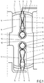
- the FIG. 1 shows two double-acting forceps springs, each with two undulating spring legs 1.
- the waveform of the legs 1 two positions are created for a bolt.
- the bolt can be moved back and forth linearly between a position or position 2 and a position or position 3.
- the legs 1 of each in the present case one-piece forceps spring in a central region between the two positions 2 and 3 have to be pressed apart against a spring tension.
- a rest position 2, 3 of each bolt is secured by the two legs 1 of a spring.
- the movement of the legs 1 is limited to the outside by walls 4, which serve as a stop. These limit the movement of the legs 1, which is effected by adjusting the position of a bolt from 2 to 3 or vice versa. It is thus achieved that a bolt is secured against displacement at high accelerations, without having to use excessively sized springs, so feathers with large spring constants.
- Two walls 4 are parallel to each other and parallel to the longitudinal extension of the associated spring with the legs 1.
- Two walls 5 serve to hold or fixing free ends of the legs 1.
- a wall portion 6 between the two legs 1 of a spring in the free Ends also serves to hold or fix the free ends of the legs 1. In particular, the free ends of the legs 1 are held and fixed by the walls 5 and 6 positively and / or non-positively.
- each one-piece spring which is opposite the free ends of the legs 1, extends in a circle around a pin 8 of the housing 9 around.
- a laterally projecting from the bolt 8 web 10 helps to hold the end 7 of each spring positively.
- the end 7 is also surrounded by a wall 11, which also contributes to a positive retention of the end 7 of each spring.
- the end 7 is also fixed.
- FIG. 1 an upper position assurance and a lower position assurance is shown. Mechanically, both position safeguards are identical in construction with the exception of the bolt.
- the bolt of the upper position lock has a smaller diameter than the bolt of the lower position lock. Due to the smaller diameter is the upper position guard has grown lower acceleration forces compared to the lower position guard.
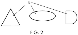
- the in the FIG. 1 shown bolts have a circular diameter. These are cylindrical pins. Instead of a circular diameter, the diameter of a bolt for the aforementioned reasons, for example, triangular, semicircular or oval.
- FIG. 2 show other embodiments of cross sections of bolts 9, which can be used alternatively in a position assurance. Shown is a triangular cross section, an oval cross section and a flattened circular shape. Depending on the shape, the dimensioning and the installation direction desired acceleration forces can be adjusted in a position assurance, which has grown a position assurance.
Landscapes
- Lock And Its Accessories (AREA)
Claims (8)
- Serrure dotée d'un dispositif d'encliquetage comprenant un loquet tournant et un cliquet d'arrêt servant à bloquer le loquet tournant, et avec un dispositif de blocage de la position doté d'un ressort, servant au verrouillage ou à protéger contre les vols.
à savoir que• le ressort est un double ressort à pince (1, 7), doté de deux branches de ressort (1) qui doivent être bougées en même temps pour pouvoir modifier la position de verrouillage ou du dispositif anti-vol ;• un boulon (2), par exemple une goupille cylindrique est prévue, sur laquelle agit des deux côtés le ressort à pince (1, 7) à titre de blocage de position ;caractérisée en ce que• une butée est prévue (4) pour la branche de ressort (1) ;• le mouvement effectué par la branche de ressort (1) vers l'extérieur est limité par deux parois (4) qui servent de butée et qui limitent le mouvement de la branche de ressort (1). Qui est actionnée par un réglage du boulon (2) depuis une première position d'arrêt vers une deuxième position d'arrêt ou vice-versa. - Serrure selon la revendication précédente, à savoir que• Les deux parois (4) sont parallèles l'une à l'autre et parallèles à l'allongement longitudinal du ressort à pince (1, 7).
- Serrure selon la revendication précédente, caractérisée en ce que• pour modifier la position d'un verrouillage ou d'un dispositif anti-vol, le boulon (2) doit être déplacé linéairement.
- Serrure selon la revendication précédente, caractérisée en ce que• une ou deux extrémités (7) de chaque branche (1) sont fixées.
- Serrure selon une des revendications précédentes, caractérisée en ce qu'• est prévu un moteur permettant de modifier la position du verrouillage ou celle du dispositif anti-vol.
- Serrure selon une des revendications précédentes, caractérisée en ce que le dispositif de blocage de la position peut, face aux forces d'accélération pouvant aller jusqu'à 30 g, sécuriser une position pouvant aller jusqu'à 55 g.
- Système comprenant au moins deux serrures selon une des revendications précédentes, à savoir que• les ressorts utilisés (1, 7) pour chaque dispositif de blocage de position sont identiques pour une serrure chacun et qu'un boulon (2) d'un dispositif de blocage de position se distingue d'un boulon (2) d'un autre dispositif de blocage de position par son diamètre et/ou sa coupe transversale et/ou son sens de montage pour les diamètres non circulaires.
- Procédé de fabrication d'un grand nombre de serrures avec dispositif de blocage selon une des revendications précédentes, à savoir que• toutes les serrures à ressort (1, 7) sont fabriquées avec des tensions de ressort de forces identiques du dispositif de blocage de la position, mais pas avec des boulons (2) identiques pour tous les dispositifs de blocage de la position.
Applications Claiming Priority (2)
| Application Number | Priority Date | Filing Date | Title |
|---|---|---|---|
| DE102013212896.7A DE102013212896A1 (de) | 2013-07-02 | 2013-07-02 | Kraftfahrzeugschloss mit Positionssicherung |
| PCT/DE2014/000333 WO2015000458A1 (fr) | 2013-07-02 | 2014-07-02 | Serrure de véhicule automobile à blocage de position |
Publications (2)
| Publication Number | Publication Date |
|---|---|
| EP3017128A1 EP3017128A1 (fr) | 2016-05-11 |
| EP3017128B1 true EP3017128B1 (fr) | 2018-09-05 |
Family
ID=51392006
Family Applications (1)
| Application Number | Title | Priority Date | Filing Date |
|---|---|---|---|
| EP14754987.7A Active EP3017128B1 (fr) | 2013-07-02 | 2014-07-02 | Serrure de véhicule automobile à blocage de position |
Country Status (5)
| Country | Link |
|---|---|
| US (1) | US10113341B2 (fr) |
| EP (1) | EP3017128B1 (fr) |
| CN (1) | CN105358780B (fr) |
| DE (1) | DE102013212896A1 (fr) |
| WO (1) | WO2015000458A1 (fr) |
Families Citing this family (3)
| Publication number | Priority date | Publication date | Assignee | Title |
|---|---|---|---|---|
| DE102013213189A1 (de) | 2013-07-05 | 2015-01-08 | Kiekert Ag | Kraftfahrzeugschloss mit Positionssicherung |
| DE102014000680A1 (de) | 2014-01-22 | 2015-07-23 | Kiekert Aktiengesellschaft | Kraftfahrzeugschloss mit Positionssicherung |
| DE102020133257A1 (de) * | 2020-12-14 | 2022-06-15 | Kiekert Aktiengesellschaft | Kraftfahrzeug-Schloss, insbesondere Kraftfahrzeug-Türschloss |
Family Cites Families (30)
| Publication number | Priority date | Publication date | Assignee | Title |
|---|---|---|---|---|
| FR1564650A (fr) * | 1968-02-12 | 1969-04-25 | ||
| US5079964A (en) * | 1989-05-25 | 1992-01-14 | Mitsui Kinzoku Kogyo Kabushiki Kaisha | Actuator for door locking apparatus for vehicle |
| US5002319A (en) * | 1990-08-28 | 1991-03-26 | Rockwell International Corporation | Sheet metal latch apparatus |
| DE4108561A1 (de) | 1991-03-15 | 1992-09-17 | Bayerische Motoren Werke Ag | Schloss mit zentralverriegelungseinrichtung fuer tueren und/oder klappen an kraftfahrzeugen |
| US5257838A (en) * | 1992-11-24 | 1993-11-02 | Lin Jui Chang | Dead bolt assembly for tubular door locks |
| DE19505779A1 (de) * | 1995-02-20 | 1996-08-29 | Bocklenberg & Motte Bomoro | Kraftfahrzeug-Klappenschloß, insbesondere Heckklappenschloß |
| US6386599B1 (en) * | 1999-08-12 | 2002-05-14 | John Phillip Chevalier | Latch arrangement for automotive door |
| EP1180569A3 (fr) * | 2000-08-09 | 2003-08-06 | ITW Limited | Mécanisme de verrouillage ou de fermeture |
| JP4277441B2 (ja) * | 2000-10-27 | 2009-06-10 | アイシン精機株式会社 | 回転レバーの位置保持装置 |
| US6733052B2 (en) * | 2000-12-14 | 2004-05-11 | Delphi Technologies, Inc. | Power operated vehicle door latch |
| DE10143366A1 (de) * | 2001-09-04 | 2003-03-20 | Kiekert Ag | Kraftfahrzeugtürverschluss |
| JP4196617B2 (ja) | 2002-05-24 | 2008-12-17 | アイシン精機株式会社 | ドアロック装置 |
| DE10320457A1 (de) | 2003-05-08 | 2004-12-16 | Kiekert Ag | Kraftfahrzeugtürverschluss |
| US7377557B2 (en) * | 2004-08-20 | 2008-05-27 | Honeywell International Inc. | Scissor mechanism for a latch assembly |
| DE102006038988B4 (de) * | 2006-08-21 | 2014-05-28 | Johnson Controls Interiors Gmbh & Co. Kg | Klappe mit einer Ver- und Entriegelungsvorrichtung |
| JP4794403B2 (ja) * | 2006-10-02 | 2011-10-19 | 三井金属アクト株式会社 | ドアロック装置 |
| DE202008005016U1 (de) * | 2008-04-10 | 2009-08-13 | BROSE SCHLIEßSYSTEME GMBH & CO. KG | Kraftfahrzeugschloß |
| DE202008005128U1 (de) * | 2008-04-14 | 2008-07-10 | D. la Porte Söhne GmbH | Fahrzeugtürschloss mit Innenauslösehebel |
| JP4760887B2 (ja) * | 2008-09-29 | 2011-08-31 | アイシン精機株式会社 | ドアロック装置 |
| JP5279433B2 (ja) * | 2008-10-01 | 2013-09-04 | 株式会社ユーシン | ドアロック装置 |
| DE102008057961A1 (de) * | 2008-11-19 | 2010-05-20 | Kiekert Ag | Schlosseinheit mit Mehrklinken-Gesperre |
| JP4972803B2 (ja) * | 2010-01-26 | 2012-07-11 | 三井金属アクト株式会社 | 車両用ドアラッチ装置 |
| DE102011012651A1 (de) * | 2011-02-28 | 2012-08-30 | BROSE SCHLIEßSYSTEME GMBH & CO. KG | Sperrwerk mit Öffnungstendenz |
| DE102011018512A1 (de) | 2011-04-23 | 2012-10-25 | Kiekert Ag | Kraftfahrzeugtürverschluss |
| DE102011076704A1 (de) * | 2011-05-30 | 2012-12-06 | Kiekert Ag | Schloss für eine Klappe oder Tür |
| DE202012001961U1 (de) * | 2012-02-28 | 2013-05-29 | Kiekert Aktiengesellschaft | Kraftfahrzeugtürverschluss |
| DE102012003854A1 (de) * | 2012-02-29 | 2013-08-29 | Kiekert Ag | Kraftfahrzeugtürverschluss und Verfahren zur elektrischen Betätigung eines Gesperres |
| DE202012002858U1 (de) * | 2012-03-20 | 2013-06-24 | Kiekert Ag | Kraftfahrzeugtürverschluss |
| DE102012207441A1 (de) * | 2012-05-04 | 2013-11-07 | Kiekert Ag | Schloss für eine Klappe oder Tür |
| DE102014000680A1 (de) * | 2014-01-22 | 2015-07-23 | Kiekert Aktiengesellschaft | Kraftfahrzeugschloss mit Positionssicherung |
-
2013
- 2013-07-02 DE DE102013212896.7A patent/DE102013212896A1/de not_active Withdrawn
-
2014
- 2014-07-02 WO PCT/DE2014/000333 patent/WO2015000458A1/fr not_active Ceased
- 2014-07-02 EP EP14754987.7A patent/EP3017128B1/fr active Active
- 2014-07-02 CN CN201480037956.7A patent/CN105358780B/zh active Active
- 2014-07-02 US US14/901,755 patent/US10113341B2/en active Active
Also Published As
| Publication number | Publication date |
|---|---|
| DE102013212896A1 (de) | 2015-01-08 |
| EP3017128A1 (fr) | 2016-05-11 |
| WO2015000458A1 (fr) | 2015-01-08 |
| US10113341B2 (en) | 2018-10-30 |
| US20160208524A1 (en) | 2016-07-21 |
| CN105358780B (zh) | 2017-12-19 |
| CN105358780A (zh) | 2016-02-24 |
Similar Documents
| Publication | Publication Date | Title |
|---|---|---|
| EP3612697B1 (fr) | Serrure pour véhicule à moteur | |
| EP2702218B1 (fr) | Système de fermeture de porte de véhicule automobile | |
| EP2362041B1 (fr) | Verrouillage de protection contre les mines pour l'agencement sur des portes de véhicules militaires | |
| EP2291571B1 (fr) | Dispositif de fermeture comprenant un ressort à cliquet | |
| EP2925945B1 (fr) | Serrure de véhicule automobile | |
| DE102014004552A1 (de) | Betätigungseinrichtung für ein Kraftfahrzeugschloss | |
| EP2828456B1 (fr) | Verrouillage de portière de véhicule automobile | |
| EP3097244B1 (fr) | Serrure de véhicule automobile avec blocage de position | |
| EP3841265B1 (fr) | Serrure de véhicule automobile, en particulier serrure de véhicule automobile pouvant être actionnée de manière électrique | |
| EP3017128B1 (fr) | Serrure de véhicule automobile à blocage de position | |
| DE102017216920A1 (de) | Türgriffeinrichtung für eine Tür eines Kraftfahrzeugs, Tür, Kraftfahrzeug | |
| EP4301952A1 (fr) | Verrou de véhicule automobile | |
| EP2844812B1 (fr) | Serrure pour une trappe ou une porte | |
| EP3132962B1 (fr) | Couvercle de reservoir dote d'un dispositif de deverrouillage a base de materiau a memoire de forme | |
| EP2929113B1 (fr) | Serrure pour une coffre ou une porte | |
| EP3017129B1 (fr) | Serrure de véhicule automobile à blocage de position | |
| EP2670934B1 (fr) | Serrure de véhicule à moteur | |
| EP4136300B1 (fr) | Verrou de véhicule automobile, en particulier verrou de portière de véhicule automobile | |
| DE3907632A1 (de) | Schloss mit sicherungseinrichtung, insbesondere fuer fahrzeugtueren | |
| EP3536882B1 (fr) | Serrure pour un battant | |
| DE102007012684A1 (de) | Betätigungsvorrichtung zur Betätigung einer Schlossbaugruppe eines Kraftfahrzeugs | |
| EP2473689B1 (fr) | Serrure de véhicule à moteur | |
| DE102019124646B4 (de) | Verriegelungseinrichtung | |
| DE102016112508A1 (de) | Schließvorrichtung mit Trägheitskupplung | |
| DE102023106526A1 (de) | Kraftfahrzeugschloss |
Legal Events
| Date | Code | Title | Description |
|---|---|---|---|
| PUAI | Public reference made under article 153(3) epc to a published international application that has entered the european phase |
Free format text: ORIGINAL CODE: 0009012 |
|
| 17P | Request for examination filed |
Effective date: 20151210 |
|
| AK | Designated contracting states |
Kind code of ref document: A1 Designated state(s): AL AT BE BG CH CY CZ DE DK EE ES FI FR GB GR HR HU IE IS IT LI LT LU LV MC MK MT NL NO PL PT RO RS SE SI SK SM TR |
|
| AX | Request for extension of the european patent |
Extension state: BA ME |
|
| DAX | Request for extension of the european patent (deleted) | ||
| GRAP | Despatch of communication of intention to grant a patent |
Free format text: ORIGINAL CODE: EPIDOSNIGR1 |
|
| STAA | Information on the status of an ep patent application or granted ep patent |
Free format text: STATUS: GRANT OF PATENT IS INTENDED |
|
| INTG | Intention to grant announced |
Effective date: 20180321 |
|
| GRAS | Grant fee paid |
Free format text: ORIGINAL CODE: EPIDOSNIGR3 |
|
| GRAA | (expected) grant |
Free format text: ORIGINAL CODE: 0009210 |
|
| STAA | Information on the status of an ep patent application or granted ep patent |
Free format text: STATUS: THE PATENT HAS BEEN GRANTED |
|
| AK | Designated contracting states |
Kind code of ref document: B1 Designated state(s): AL AT BE BG CH CY CZ DE DK EE ES FI FR GB GR HR HU IE IS IT LI LT LU LV MC MK MT NL NO PL PT RO RS SE SI SK SM TR |
|
| REG | Reference to a national code |
Ref country code: GB Ref legal event code: FG4D Free format text: NOT ENGLISH |
|
| REG | Reference to a national code |
Ref country code: CH Ref legal event code: EP |
|
| REG | Reference to a national code |
Ref country code: AT Ref legal event code: REF Ref document number: 1037988 Country of ref document: AT Kind code of ref document: T Effective date: 20180915 |
|
| REG | Reference to a national code |
Ref country code: IE Ref legal event code: FG4D Free format text: LANGUAGE OF EP DOCUMENT: GERMAN |
|
| REG | Reference to a national code |
Ref country code: DE Ref legal event code: R096 Ref document number: 502014009400 Country of ref document: DE |
|
| REG | Reference to a national code |
Ref country code: NL Ref legal event code: MP Effective date: 20180905 |
|
| REG | Reference to a national code |
Ref country code: LT Ref legal event code: MG4D |
|
| PG25 | Lapsed in a contracting state [announced via postgrant information from national office to epo] |
Ref country code: BG Free format text: LAPSE BECAUSE OF FAILURE TO SUBMIT A TRANSLATION OF THE DESCRIPTION OR TO PAY THE FEE WITHIN THE PRESCRIBED TIME-LIMIT Effective date: 20181205 Ref country code: SE Free format text: LAPSE BECAUSE OF FAILURE TO SUBMIT A TRANSLATION OF THE DESCRIPTION OR TO PAY THE FEE WITHIN THE PRESCRIBED TIME-LIMIT Effective date: 20180905 Ref country code: LT Free format text: LAPSE BECAUSE OF FAILURE TO SUBMIT A TRANSLATION OF THE DESCRIPTION OR TO PAY THE FEE WITHIN THE PRESCRIBED TIME-LIMIT Effective date: 20180905 Ref country code: FI Free format text: LAPSE BECAUSE OF FAILURE TO SUBMIT A TRANSLATION OF THE DESCRIPTION OR TO PAY THE FEE WITHIN THE PRESCRIBED TIME-LIMIT Effective date: 20180905 Ref country code: GR Free format text: LAPSE BECAUSE OF FAILURE TO SUBMIT A TRANSLATION OF THE DESCRIPTION OR TO PAY THE FEE WITHIN THE PRESCRIBED TIME-LIMIT Effective date: 20181206 Ref country code: RS Free format text: LAPSE BECAUSE OF FAILURE TO SUBMIT A TRANSLATION OF THE DESCRIPTION OR TO PAY THE FEE WITHIN THE PRESCRIBED TIME-LIMIT Effective date: 20180905 Ref country code: NO Free format text: LAPSE BECAUSE OF FAILURE TO SUBMIT A TRANSLATION OF THE DESCRIPTION OR TO PAY THE FEE WITHIN THE PRESCRIBED TIME-LIMIT Effective date: 20181205 |
|
| PG25 | Lapsed in a contracting state [announced via postgrant information from national office to epo] |
Ref country code: AL Free format text: LAPSE BECAUSE OF FAILURE TO SUBMIT A TRANSLATION OF THE DESCRIPTION OR TO PAY THE FEE WITHIN THE PRESCRIBED TIME-LIMIT Effective date: 20180905 Ref country code: HR Free format text: LAPSE BECAUSE OF FAILURE TO SUBMIT A TRANSLATION OF THE DESCRIPTION OR TO PAY THE FEE WITHIN THE PRESCRIBED TIME-LIMIT Effective date: 20180905 Ref country code: LV Free format text: LAPSE BECAUSE OF FAILURE TO SUBMIT A TRANSLATION OF THE DESCRIPTION OR TO PAY THE FEE WITHIN THE PRESCRIBED TIME-LIMIT Effective date: 20180905 |
|
| PG25 | Lapsed in a contracting state [announced via postgrant information from national office to epo] |
Ref country code: PL Free format text: LAPSE BECAUSE OF FAILURE TO SUBMIT A TRANSLATION OF THE DESCRIPTION OR TO PAY THE FEE WITHIN THE PRESCRIBED TIME-LIMIT Effective date: 20180905 Ref country code: NL Free format text: LAPSE BECAUSE OF FAILURE TO SUBMIT A TRANSLATION OF THE DESCRIPTION OR TO PAY THE FEE WITHIN THE PRESCRIBED TIME-LIMIT Effective date: 20180905 Ref country code: IT Free format text: LAPSE BECAUSE OF FAILURE TO SUBMIT A TRANSLATION OF THE DESCRIPTION OR TO PAY THE FEE WITHIN THE PRESCRIBED TIME-LIMIT Effective date: 20180905 Ref country code: EE Free format text: LAPSE BECAUSE OF FAILURE TO SUBMIT A TRANSLATION OF THE DESCRIPTION OR TO PAY THE FEE WITHIN THE PRESCRIBED TIME-LIMIT Effective date: 20180905 Ref country code: RO Free format text: LAPSE BECAUSE OF FAILURE TO SUBMIT A TRANSLATION OF THE DESCRIPTION OR TO PAY THE FEE WITHIN THE PRESCRIBED TIME-LIMIT Effective date: 20180905 Ref country code: ES Free format text: LAPSE BECAUSE OF FAILURE TO SUBMIT A TRANSLATION OF THE DESCRIPTION OR TO PAY THE FEE WITHIN THE PRESCRIBED TIME-LIMIT Effective date: 20180905 Ref country code: IS Free format text: LAPSE BECAUSE OF FAILURE TO SUBMIT A TRANSLATION OF THE DESCRIPTION OR TO PAY THE FEE WITHIN THE PRESCRIBED TIME-LIMIT Effective date: 20190105 |
|
| PG25 | Lapsed in a contracting state [announced via postgrant information from national office to epo] |
Ref country code: SK Free format text: LAPSE BECAUSE OF FAILURE TO SUBMIT A TRANSLATION OF THE DESCRIPTION OR TO PAY THE FEE WITHIN THE PRESCRIBED TIME-LIMIT Effective date: 20180905 Ref country code: PT Free format text: LAPSE BECAUSE OF FAILURE TO SUBMIT A TRANSLATION OF THE DESCRIPTION OR TO PAY THE FEE WITHIN THE PRESCRIBED TIME-LIMIT Effective date: 20190105 Ref country code: SM Free format text: LAPSE BECAUSE OF FAILURE TO SUBMIT A TRANSLATION OF THE DESCRIPTION OR TO PAY THE FEE WITHIN THE PRESCRIBED TIME-LIMIT Effective date: 20180905 |
|
| REG | Reference to a national code |
Ref country code: DE Ref legal event code: R097 Ref document number: 502014009400 Country of ref document: DE |
|
| PLBE | No opposition filed within time limit |
Free format text: ORIGINAL CODE: 0009261 |
|
| STAA | Information on the status of an ep patent application or granted ep patent |
Free format text: STATUS: NO OPPOSITION FILED WITHIN TIME LIMIT |
|
| PG25 | Lapsed in a contracting state [announced via postgrant information from national office to epo] |
Ref country code: DK Free format text: LAPSE BECAUSE OF FAILURE TO SUBMIT A TRANSLATION OF THE DESCRIPTION OR TO PAY THE FEE WITHIN THE PRESCRIBED TIME-LIMIT Effective date: 20180905 |
|
| 26N | No opposition filed |
Effective date: 20190606 |
|
| PG25 | Lapsed in a contracting state [announced via postgrant information from national office to epo] |
Ref country code: SI Free format text: LAPSE BECAUSE OF FAILURE TO SUBMIT A TRANSLATION OF THE DESCRIPTION OR TO PAY THE FEE WITHIN THE PRESCRIBED TIME-LIMIT Effective date: 20180905 |
|
| PG25 | Lapsed in a contracting state [announced via postgrant information from national office to epo] |
Ref country code: MC Free format text: LAPSE BECAUSE OF FAILURE TO SUBMIT A TRANSLATION OF THE DESCRIPTION OR TO PAY THE FEE WITHIN THE PRESCRIBED TIME-LIMIT Effective date: 20180905 |
|
| REG | Reference to a national code |
Ref country code: CH Ref legal event code: PL |
|
| GBPC | Gb: european patent ceased through non-payment of renewal fee |
Effective date: 20190702 |
|
| PG25 | Lapsed in a contracting state [announced via postgrant information from national office to epo] |
Ref country code: TR Free format text: LAPSE BECAUSE OF FAILURE TO SUBMIT A TRANSLATION OF THE DESCRIPTION OR TO PAY THE FEE WITHIN THE PRESCRIBED TIME-LIMIT Effective date: 20180905 |
|
| REG | Reference to a national code |
Ref country code: BE Ref legal event code: MM Effective date: 20190731 |
|
| PG25 | Lapsed in a contracting state [announced via postgrant information from national office to epo] |
Ref country code: GB Free format text: LAPSE BECAUSE OF NON-PAYMENT OF DUE FEES Effective date: 20190702 |
|
| PG25 | Lapsed in a contracting state [announced via postgrant information from national office to epo] |
Ref country code: LI Free format text: LAPSE BECAUSE OF NON-PAYMENT OF DUE FEES Effective date: 20190731 Ref country code: CH Free format text: LAPSE BECAUSE OF NON-PAYMENT OF DUE FEES Effective date: 20190731 Ref country code: BE Free format text: LAPSE BECAUSE OF NON-PAYMENT OF DUE FEES Effective date: 20190731 Ref country code: LU Free format text: LAPSE BECAUSE OF NON-PAYMENT OF DUE FEES Effective date: 20190702 |
|
| PG25 | Lapsed in a contracting state [announced via postgrant information from national office to epo] |
Ref country code: IE Free format text: LAPSE BECAUSE OF NON-PAYMENT OF DUE FEES Effective date: 20190702 |
|
| REG | Reference to a national code |
Ref country code: AT Ref legal event code: MM01 Ref document number: 1037988 Country of ref document: AT Kind code of ref document: T Effective date: 20190702 |
|
| PG25 | Lapsed in a contracting state [announced via postgrant information from national office to epo] |
Ref country code: AT Free format text: LAPSE BECAUSE OF NON-PAYMENT OF DUE FEES Effective date: 20190702 |
|
| PG25 | Lapsed in a contracting state [announced via postgrant information from national office to epo] |
Ref country code: CY Free format text: LAPSE BECAUSE OF FAILURE TO SUBMIT A TRANSLATION OF THE DESCRIPTION OR TO PAY THE FEE WITHIN THE PRESCRIBED TIME-LIMIT Effective date: 20180905 |
|
| PG25 | Lapsed in a contracting state [announced via postgrant information from national office to epo] |
Ref country code: HU Free format text: LAPSE BECAUSE OF FAILURE TO SUBMIT A TRANSLATION OF THE DESCRIPTION OR TO PAY THE FEE WITHIN THE PRESCRIBED TIME-LIMIT; INVALID AB INITIO Effective date: 20140702 Ref country code: MT Free format text: LAPSE BECAUSE OF FAILURE TO SUBMIT A TRANSLATION OF THE DESCRIPTION OR TO PAY THE FEE WITHIN THE PRESCRIBED TIME-LIMIT Effective date: 20180905 |
|
| PG25 | Lapsed in a contracting state [announced via postgrant information from national office to epo] |
Ref country code: MK Free format text: LAPSE BECAUSE OF FAILURE TO SUBMIT A TRANSLATION OF THE DESCRIPTION OR TO PAY THE FEE WITHIN THE PRESCRIBED TIME-LIMIT Effective date: 20180905 |
|
| P01 | Opt-out of the competence of the unified patent court (upc) registered |
Effective date: 20230529 |
|
| PGFP | Annual fee paid to national office [announced via postgrant information from national office to epo] |
Ref country code: CZ Payment date: 20250619 Year of fee payment: 12 |
|
| PGFP | Annual fee paid to national office [announced via postgrant information from national office to epo] |
Ref country code: DE Payment date: 20250722 Year of fee payment: 12 |
|
| PGFP | Annual fee paid to national office [announced via postgrant information from national office to epo] |
Ref country code: FR Payment date: 20250723 Year of fee payment: 12 |