EP3017226B1 - Schlauch mit optimierten stahldrahtverstärkungsschichten - Google Patents
Schlauch mit optimierten stahldrahtverstärkungsschichten Download PDFInfo
- Publication number
- EP3017226B1 EP3017226B1 EP14733170.6A EP14733170A EP3017226B1 EP 3017226 B1 EP3017226 B1 EP 3017226B1 EP 14733170 A EP14733170 A EP 14733170A EP 3017226 B1 EP3017226 B1 EP 3017226B1
- Authority
- EP
- European Patent Office
- Prior art keywords
- steel wire
- reinforcement layer
- wires
- steel
- ratio
- Prior art date
- Legal status (The legal status is an assumption and is not a legal conclusion. Google has not performed a legal analysis and makes no representation as to the accuracy of the status listed.)
- Active
Links
Images


Classifications
-
- B—PERFORMING OPERATIONS; TRANSPORTING
- B32—LAYERED PRODUCTS
- B32B—LAYERED PRODUCTS, i.e. PRODUCTS BUILT-UP OF STRATA OF FLAT OR NON-FLAT, e.g. CELLULAR OR HONEYCOMB, FORM
- B32B7/00—Layered products characterised by the relation between layers; Layered products characterised by the relative orientation of features between layers, or by the relative values of a measurable parameter between layers, i.e. products comprising layers having different physical, chemical or physicochemical properties; Layered products characterised by the interconnection of layers
- B32B7/02—Physical, chemical or physicochemical properties
- B32B7/022—Mechanical properties
-
- B—PERFORMING OPERATIONS; TRANSPORTING
- B32—LAYERED PRODUCTS
- B32B—LAYERED PRODUCTS, i.e. PRODUCTS BUILT-UP OF STRATA OF FLAT OR NON-FLAT, e.g. CELLULAR OR HONEYCOMB, FORM
- B32B1/00—Layered products having a non-planar shape
- B32B1/08—Tubular products
-
- B—PERFORMING OPERATIONS; TRANSPORTING
- B32—LAYERED PRODUCTS
- B32B—LAYERED PRODUCTS, i.e. PRODUCTS BUILT-UP OF STRATA OF FLAT OR NON-FLAT, e.g. CELLULAR OR HONEYCOMB, FORM
- B32B27/00—Layered products comprising a layer of synthetic resin
- B32B27/12—Layered products comprising a layer of synthetic resin next to a fibrous or filamentary layer
-
- F—MECHANICAL ENGINEERING; LIGHTING; HEATING; WEAPONS; BLASTING
- F16—ENGINEERING ELEMENTS AND UNITS; GENERAL MEASURES FOR PRODUCING AND MAINTAINING EFFECTIVE FUNCTIONING OF MACHINES OR INSTALLATIONS; THERMAL INSULATION IN GENERAL
- F16L—PIPES; JOINTS OR FITTINGS FOR PIPES; SUPPORTS FOR PIPES, CABLES OR PROTECTIVE TUBING; MEANS FOR THERMAL INSULATION IN GENERAL
- F16L11/00—Hoses, i.e. flexible pipes
- F16L11/04—Hoses, i.e. flexible pipes made of rubber or flexible plastics
- F16L11/08—Hoses, i.e. flexible pipes made of rubber or flexible plastics with reinforcements embedded in the wall
- F16L11/081—Hoses, i.e. flexible pipes made of rubber or flexible plastics with reinforcements embedded in the wall comprising one or more layers of a helically wound cord or wire
- F16L11/082—Hoses, i.e. flexible pipes made of rubber or flexible plastics with reinforcements embedded in the wall comprising one or more layers of a helically wound cord or wire two layers
-
- F—MECHANICAL ENGINEERING; LIGHTING; HEATING; WEAPONS; BLASTING
- F16—ENGINEERING ELEMENTS AND UNITS; GENERAL MEASURES FOR PRODUCING AND MAINTAINING EFFECTIVE FUNCTIONING OF MACHINES OR INSTALLATIONS; THERMAL INSULATION IN GENERAL
- F16L—PIPES; JOINTS OR FITTINGS FOR PIPES; SUPPORTS FOR PIPES, CABLES OR PROTECTIVE TUBING; MEANS FOR THERMAL INSULATION IN GENERAL
- F16L11/00—Hoses, i.e. flexible pipes
- F16L11/04—Hoses, i.e. flexible pipes made of rubber or flexible plastics
- F16L11/08—Hoses, i.e. flexible pipes made of rubber or flexible plastics with reinforcements embedded in the wall
- F16L11/081—Hoses, i.e. flexible pipes made of rubber or flexible plastics with reinforcements embedded in the wall comprising one or more layers of a helically wound cord or wire
- F16L11/083—Hoses, i.e. flexible pipes made of rubber or flexible plastics with reinforcements embedded in the wall comprising one or more layers of a helically wound cord or wire three or more layers
-
- F—MECHANICAL ENGINEERING; LIGHTING; HEATING; WEAPONS; BLASTING
- F16—ENGINEERING ELEMENTS AND UNITS; GENERAL MEASURES FOR PRODUCING AND MAINTAINING EFFECTIVE FUNCTIONING OF MACHINES OR INSTALLATIONS; THERMAL INSULATION IN GENERAL
- F16L—PIPES; JOINTS OR FITTINGS FOR PIPES; SUPPORTS FOR PIPES, CABLES OR PROTECTIVE TUBING; MEANS FOR THERMAL INSULATION IN GENERAL
- F16L11/00—Hoses, i.e. flexible pipes
- F16L11/04—Hoses, i.e. flexible pipes made of rubber or flexible plastics
- F16L11/08—Hoses, i.e. flexible pipes made of rubber or flexible plastics with reinforcements embedded in the wall
- F16L11/085—Hoses, i.e. flexible pipes made of rubber or flexible plastics with reinforcements embedded in the wall comprising one or more braided layers
- F16L11/086—Hoses, i.e. flexible pipes made of rubber or flexible plastics with reinforcements embedded in the wall comprising one or more braided layers two layers
-
- F—MECHANICAL ENGINEERING; LIGHTING; HEATING; WEAPONS; BLASTING
- F16—ENGINEERING ELEMENTS AND UNITS; GENERAL MEASURES FOR PRODUCING AND MAINTAINING EFFECTIVE FUNCTIONING OF MACHINES OR INSTALLATIONS; THERMAL INSULATION IN GENERAL
- F16L—PIPES; JOINTS OR FITTINGS FOR PIPES; SUPPORTS FOR PIPES, CABLES OR PROTECTIVE TUBING; MEANS FOR THERMAL INSULATION IN GENERAL
- F16L11/00—Hoses, i.e. flexible pipes
- F16L11/04—Hoses, i.e. flexible pipes made of rubber or flexible plastics
- F16L11/08—Hoses, i.e. flexible pipes made of rubber or flexible plastics with reinforcements embedded in the wall
- F16L11/085—Hoses, i.e. flexible pipes made of rubber or flexible plastics with reinforcements embedded in the wall comprising one or more braided layers
- F16L11/087—Hoses, i.e. flexible pipes made of rubber or flexible plastics with reinforcements embedded in the wall comprising one or more braided layers three or more layers
-
- F—MECHANICAL ENGINEERING; LIGHTING; HEATING; WEAPONS; BLASTING
- F16—ENGINEERING ELEMENTS AND UNITS; GENERAL MEASURES FOR PRODUCING AND MAINTAINING EFFECTIVE FUNCTIONING OF MACHINES OR INSTALLATIONS; THERMAL INSULATION IN GENERAL
- F16L—PIPES; JOINTS OR FITTINGS FOR PIPES; SUPPORTS FOR PIPES, CABLES OR PROTECTIVE TUBING; MEANS FOR THERMAL INSULATION IN GENERAL
- F16L11/00—Hoses, i.e. flexible pipes
- F16L11/04—Hoses, i.e. flexible pipes made of rubber or flexible plastics
- F16L11/08—Hoses, i.e. flexible pipes made of rubber or flexible plastics with reinforcements embedded in the wall
- F16L11/088—Hoses, i.e. flexible pipes made of rubber or flexible plastics with reinforcements embedded in the wall comprising a combination of one or more layers of a helically wound cord or wire with one or more braided layers
-
- B—PERFORMING OPERATIONS; TRANSPORTING
- B32—LAYERED PRODUCTS
- B32B—LAYERED PRODUCTS, i.e. PRODUCTS BUILT-UP OF STRATA OF FLAT OR NON-FLAT, e.g. CELLULAR OR HONEYCOMB, FORM
- B32B2262/00—Composition or structural features of fibres which form a fibrous or filamentary layer or are present as additives
- B32B2262/10—Inorganic fibres
- B32B2262/103—Metal fibres
-
- B—PERFORMING OPERATIONS; TRANSPORTING
- B32—LAYERED PRODUCTS
- B32B—LAYERED PRODUCTS, i.e. PRODUCTS BUILT-UP OF STRATA OF FLAT OR NON-FLAT, e.g. CELLULAR OR HONEYCOMB, FORM
- B32B2274/00—Thermoplastic elastomer material
-
- B—PERFORMING OPERATIONS; TRANSPORTING
- B32—LAYERED PRODUCTS
- B32B—LAYERED PRODUCTS, i.e. PRODUCTS BUILT-UP OF STRATA OF FLAT OR NON-FLAT, e.g. CELLULAR OR HONEYCOMB, FORM
- B32B2307/00—Properties of the layers or laminate
- B32B2307/50—Properties of the layers or laminate having particular mechanical properties
- B32B2307/51—Elastic
-
- B—PERFORMING OPERATIONS; TRANSPORTING
- B32—LAYERED PRODUCTS
- B32B—LAYERED PRODUCTS, i.e. PRODUCTS BUILT-UP OF STRATA OF FLAT OR NON-FLAT, e.g. CELLULAR OR HONEYCOMB, FORM
- B32B2307/00—Properties of the layers or laminate
- B32B2307/50—Properties of the layers or laminate having particular mechanical properties
- B32B2307/54—Yield strength; Tensile strength
-
- B—PERFORMING OPERATIONS; TRANSPORTING
- B32—LAYERED PRODUCTS
- B32B—LAYERED PRODUCTS, i.e. PRODUCTS BUILT-UP OF STRATA OF FLAT OR NON-FLAT, e.g. CELLULAR OR HONEYCOMB, FORM
- B32B2597/00—Tubular articles, e.g. hoses, pipes
Definitions
- the invention relates to hoses for conveying fluids under pressure that are also known as high pressure hoses or hydraulic hoses and to a method to produce such kind of hose.
- High pressure, flexible hoses for conveying fluids under high pressure such as hydraulic oil, water, but also steam or gasses are omnipresent in all kinds of equipment and vehicles to effectively transfer motion or fluids between parts that can move relative to one another.
- these kind of hoses consist of an elastomer core tube that contains the fluid around which one or more reinforcement layers have been spirally wound while being radially separated by intermediate layers of elastomer material.
- An outer layer is generally applied on the outermost reinforcement layer for covering the reinforcement such that it does not get damaged.
- the reinforcement layer is crucial to the functioning of the hose in that it does not only impart strength to the hose but also keeps the hose flexible.
- the reinforcement layer must be able to withstand highly variable pressures with shock waves propagating through the fluid. As hoses are many times used in harsh environments and convey aggressive fluids at high or low temperatures the reinforcement layer must maintain its properties of strength, flexibility and fatigue resistance also in these circumstances.
- the steel wires can be applied around the core tube in a number of ways such as in:
- the steel wires in the hose are wound under a helix angle that is conventionally set as the angle between the tangent vector to the steel wire and the axis of the helix.
- the neutral angle is Atan 2 which is about 54°44'.
- the primary object of the invention is to provide a hose that does away with the drawbacks of the prior art. It is a further object of the invention to provide a reinforcement a hose that has an optimal load sharing between all reinforcement layers so that at burst all reinforcement is loaded equally and to its maximum. A further objective is to have an optimal load sharing in the hose reinforcement not only at burst pressure but also on any intermediate pressure up to burst pressure in order to improve the impulse life of the hose. Further, an increased flexibility of the hose is aimed at. Another object is to provide a hose with a minimum of different reinforcement materials to reduce material stock. Further, it is the objective of the inventors to provide a method to produce the advantageous hose. As a last objective of the invention the materials fed to the hose building machine are equal and the changes are brought on the wire in the hose building machine itself or on the rewinder that spools the wire bundles on bobbins for the hose building machine.
- a hose for conveying fluids under pressure as defined by the features of claim 1 is claimed.
- the hose is built up around an elastomer core tube as known in the art.
- the tube can be extruded on a mandrel or the tube can be self-supporting. It is made of an elastomer material that is compatible with the fluid to be conveyed.
- the hose comprises at least two reinforcement layers at discrete reinforcement radii. At least two of those reinforcement layers comprise steel wires helically wound around the axis of the hose.
- a reinforcement layer refers to either a single layer of spiralled wires in case of a spiralled layer or the doubled layer of braided wires in case of a braided layer. In both cases the reinforcement layer is present at a discrete radius from the axis of the hose.
- the at least two reinforcement layers are radially separated by intermediate elastomer material layers.
- the intermediate elastomer material layers are important in that they transfer stresses through the pipe wall from one reinforcement layer to the next.
- Intermediate elastomer material should also adhere well to the reinforcement layers in order to preserve integrity of the hose.
- the thickness of the intermediate layer can be practically null for example for thermoplastic hoses as layers can be glued to one another.
- the thickness is of the order of magnitude of the steel wire reinforcement layer thickness i.e. between a quarter to four times the diameter of the steel wire.
- the hose is finished by a protective layer covering the outermost reinforcement layers.
- the protective layer can be made of an elastomer material or another harder material. Possibly it comprises textile materials for increasing the wear resistance of the hose.
- an elastic polymer material is meant that can either be thermosetting (requiring vulcanisation or heat treatment) or thermoplastic.
- Thermosetting elastomers are typically rubber materials such as natural or synthetic rubbers. Synthetic rubbers like NBR (Acrylonitrile Butadiene), SBR (Styrene Butadiene), EPDM (Ethylene Propylene Diene Monomer) or CR (Polychloroprene) or silicone rubbers are favoured for use in hoses. Of course different additives can be added to the polymer to adapt its properties.
- Thermoplastic elastomeric materials can be e.g. thermoplastic polyurethanes, thermoplastic polyamides, polyolefin blends, thermoplastic co-polyesters, thermoplastic fluoropolymers such as polyvinylidene difluoride, or even polyoxymethylene (POM). Although their use is not so widespread as rubber hose material, they find specific uses in niche applications.
- thermoplastic polyurethanes thermoplastic polyamides, polyolefin blends, thermoplastic co-polyesters, thermoplastic fluoropolymers such as polyvinylidene difluoride, or even polyoxymethylene (POM).
- the invention is characterised by the inventive adaptations of the steel wires used in the at least two steel wire reinforcement layers.
- Practical steel compositions of the steel wire used for the reinforcement of high pressure hoses - called hose reinforcement wire - do not only comprise iron and carbon but also other alloy and trace elements, some of which have a profound influence on the properties of the steel in terms of strength, ductility, formability, corrosion resistance and others.
- the remainder of the steel is iron and other elements that have other influences on the steel:
- chromium 0.005 to 0.30%wt
- vanadium 0.005 to 0.30%wt
- nickel 0.05-0.30%wt
- molybdenum 0.05-0.25%wt
- boron traces may reduce the formation of grain boundary cementite for carbon contents above the eutectoid composition (0.80%wt C) and thereby improve the formability of the wire.
- Such alloying enables carbon contents of 0.90 to 1.20%wt, resulting in ultimate tensile strengths that can be higher as 4000 MPa in drawn wires.
- hose reinforcement wire made from stainless steels may be employed.
- Preferred stainless steels contain a minimum of 12%Cr and a substantial amount of nickel.
- More preferred stainless steel compositions are austenitic stainless steels as these can easily be drawn to fine diameters.
- the more preferred compositions are those known in the art as AISI 302 (particularly the 'Heading Quality' HQ), AISI 301, AISI 304 and AISI 314.
- 'AISI' is the abbreviation of 'American Iron and Steel Institute'.
- Hose reinforcement wires predominantly have a round, circular cross section. However it has advantages to use flattened wires as disclosed in WO 2005/108846 . The use of such flattened wires is a priory not excluded from the current invention. Round hose reinforcement wires are available in diameters from 0.15 to 0.80 mm in steps of 0.05 mm. Sometimes intermediate diameters such as 0.28, 0.33, 0.56, 0.61, or 0.71 mm are provided to accommodate for optimised standard hoses. In general in braided reinforcement layers wires with a diameter of less than or about 0.40 mm are used. For spiralled hoses mainly thicker wires are used up to 0.80 mm.
- the tensile strength of a hose reinforcement wire is defined as the breaking load (the force at which the wire breaks, in N) divided by its metallic surface and is expressed in N/mm 2 or MPa.
- breaking load the force at which the wire breaks, in N
- MPa the force at which the wire breaks, in N
- Hose reinforcement wire is provided with an adhesive coating layer that can be zinc, copper or brass. Alternatively organic adhesion promoters can be provided on the wire.
- a hose reinforcement wire has a 'percentage total elongation at fracture At' or simply 'elongation at break' as defined in ISO 6892:1998(E), item 4.4.3. It is the total elongation of the gauge length at the moment of fracture, expressed as a percentage of the original gauge length (in %).
- the elongation at break of the hose reinforcement wires of interest for this application comprises three components:
- an 'E-ratio' of a steel wire is defined as the ratio of the tensile strength divided by the elongation at break of that wire. It is expressed in units of N/mm 2 . It must be noted that this E-ratio - although it has the same units as a modulus - is not to be regarded as such.
- a modulus - as known from Hooke's law - implies the presence of a linear region in the stress-strain diagram starting at zero load and elongation. Wires of the current application may not show a linear region at all or at the most a very small one.
- the E-ratio corresponds to the slope of the line connecting the origin to the point at break in a stress-strain diagram.
- the inventive hose is characterised in that the steel wires of the radially outermost steel wire reinforcement layer have the highest E-ratio, the steel wires of the innermost steel wire reinforcement layer have the lowest E-ratio. These lowest and highest E-ratio differ from one another. Further, the E-ratio of any steel wire reinforcement layer is not lower than the E-ratio of any inner laying steel wire reinforcement layer. This simply means that the E-ratio must increase or be equal when stepping through the steel reinforcement layers from the radially innermost to the radially outermost layer.
- this E-ratio is between 70 000 N/mm 2 up to 200 000 N/mm 2 , or between 85 000 to 160 000 N/mm 2 or even between 90 000 N/mm 2 and 140 000 N/mm 2 for the radially outermost steel wire reinforcement layer.
- the innermost steel wire reinforcement layer must have a lower E-ratio between 30 000 N/mm 2 and 120 000 N/mm 2 , or between 40 000 and 110 000 or between 50 000 and 105 000 N/mm 2 or between 50 000 and 90 000 N/mm 2 .
- the ranges for radially outermost and innermost layer must be distinct and non-overlapping.
- ⁇ A first way to change the E-ratio is to subject the steel wires of at least the innermost layer to a heat treatment, while the steel wires of at least the outermost layer are 'as drawn'.
- a heat treatment is also known as "stress relieving treatment” and is performed by subjecting the steel wires to a high temperature above 350°C and for a certain time in a protective atmosphere.
- An 'as drawn' wire is the wire as obtained from the wire drawing machine without any additional, intentional heat treatment applied. In this way the total elongation of the wire can be easily doubled with a loss in strength of at most 20%.
- the steel wires of the outermost reinforcement layer comprises steel wires 'as drawn' i.e. without having been subjected to any thermal treatment and having an E-ratio of between 70 000 N/mm 2 up to 200 000 N/mm 2 , or between 85 000 to 160 000 N/mm 2 or even between 90 000 N/mm 2 and 140 000 N/mm 2 .
- the steel wires of at least the innermost layer comprises steel wires that have been subjected to a thermal treatment and therefor have an E-ratio between 30 000 N/mm 2 and 120 000 N/mm 2 , or between 40 000 and 110 000 or between 50 000 and 105 000 N/mm 2 or between 50 000 and 90 000 N/mm 2 . ⁇
- Another preferred way to change the E-ratio is to introduce bends or crimps in the wire.
- at least the steel wires of at least the innermost steel wire reinforcement layer have crimps or bends.
- the steel wires of the outermost reinforcement layer are then free of crimps or bends i.e. are not deformed (except of course to take the helicoidal path of the reinforcement). This is a third preferred embodiment.
- a bend in a wire is discernible by an abrupt change in direction of the wire along its path.
- a wire with a bend will show a changing radius of curvature when travelling along the wire.
- the curvature will increase (i.e. the radius of curvature is small) compared to the curvature of the segments in between where the curvature is close to zero (i.e. the radius of curvature is large).
- a crimp is two bends following one another wherein the bending direction of the first bend is opposite to that of the following bend.
- the wire shows an alternating sequence of bends in opposite directions (left, right, left, right,...) within a single plane.
- the wire takes a zig-zag shape.
- ⁇ Crimps in different planes can also be combined in order to impart an even higher structural elongation to a wire.
- a first crimp can be made in a first plane while this crimped wire is subsequently crimped in a second plane substantially perpendicular to the first plane.
- Two single crimps are then observable in two view directions that are perpendicular to one another.
- the advantage of having a bi-plane crimped reinforcement wire is that the same amount of elongation at break can be obtained within a smaller circumscribed cylinder around the wire than with a wire having a single crimp in one plane. ⁇
- the elongation at break of the steel wires with crimps or bends can be tuned to be at least 0.3% higher than the elongation at break of the straight wire.
- an extra structural elongation of plus 4% compared to the straight wire can be easily build-in into the wire.
- an additional elongation of between 0.3 to 3% or 0.3 to 2%, or even between 0.3 to 1.5% can possibly build-in into the steel wire.
- the steel wires for at least the innermost and outermost reinforcement layers are of the same tensile class. Also preferred is if the steel wires are not only of the same tensile class but also of the same diameter.
- the wires of at least the innermost reinforcement layer then only differ from those the outermost layer in that the former ones are provided with crimps or bends while the latter ones are free of crimps or bends.
- the steel wires of the outermost reinforcement layer and the innermost reinforcement layer originate from one same diameter and tensile strength class whereby the outermost reinforcement layer is in the as drawn state having an E-ratio 'A', while the innermost layer has been subjected to a heat treatment such that its E-ratio is 0.425 ⁇ A or lower.
- the inventors can tune the E-ratio to become between 0.33 ⁇ A to 0.95 ⁇ A or better between 0.50 ⁇ A and 0.90 ⁇ A to a precise and consistent degree.
- the bending or crimping is done with a fixed periodicity i.e. there is a fixed distance between successive bends or the crimps have a specific, fixed wavelength.
- the preforming of bends and crimps given to the steel wires should not be confused with the up and down movement of the steel wire ribbons in a braided configuration.
- the periodicity of the bends or the wavelength of the crimp differs from the periodicity of the interweaving pattern of the braid.
- the wire bends induced by braiding are specifically excluded from being bends or crimps according the invention.
- a method for making the hose as described above comprises the steps of:
- the steel wires of said innermost steel wire reinforcement layer have an E-ratio that is lower than the E-ratio of the steel wires of said radially outermost steel wire reinforcement layer, whereby the E-ratio of any steel wire reinforcement layer is not lower than the E-ratio of any inner laying steel wire reinforcement layer.
- the method above is preceded by applying a thermal treatment on the steel wires of at least the innermost steel wire reinforcement layer such that they show an E-ratio between 30 000 and 120 000 N/mm 2 while the E-ratio of the steel wires of at least the outermost steel wire reinforcement layer is between 70 000 N/mm 2 and 200 000 N/mm 2 .
- the above method is preceded by the preforming of the steel wires of at least the innermost steel wire reinforcement layer with a preforming device that induces crimps or bends into said steel wires.
- the preforming of the wires can be done per single wire for example by the supplier of the wire prior to winding on the customer spool. Alternatively, the preforming can be done off-line on the bobbin winders during winding of the steel wires on the machine bobbins before they are mounted on the braider or the spiralling machine.
- the wires can either be preformed individually (one preforming device per wire) or in group (one preforming device per group of wires). The latter is somewhat preferred as it reduces the number of preforming devices. In group preforming results also in a synchronised bending or crimping making the ribbons more closed as compared to individual crimping wherein gaps form between the individual filaments of a ribbon.
- a preferred alternative is if the preforming of the steel wires is performed concurrently with, in-line with, during the winding of said innermost steel wire reinforcement layer. This can be done by mounting the preforming device on the spiral winder or braider of the hose building machine. The tension of the spiral winder or braider - about 8 to 10 N - is already sufficient to induce a bend or crimp on the steel wire. The preforming is then 'in-line'
- the preforming device can for example comprise a rotatable pin of substantially polygonal shape where over said steel wires are led under tension thereby inducing periodical unidirectional bends on said steel wires.
- a group of steel wires - for example as in a braiding ribbon - are led simultaneously over the rotatable pin. In this way bends are induced in phase and of equal bending degree between steel wires and the number of rotating preforming pins can be minimised.
- the preforming device can alternatively comprise a pair of intermeshing crimping wheels where between said steel wires are led thereby inducing periodical bi-directional crimps in said wires.
- steel wires can be grouped and led together between said crimping wheels resulting in steel wires that are crimped in phase with equal amplitude. Grouping the wires also leads to a reduced number of crimping devices.
- a hose building machine is claimed.
- the hose building machine can be a wire spiral machine wherein wires are wound individually or grouped around a centrally moving intermediate hose body. At least for every spindle axis of the first deposition carrousel a preforming device is provided.
- the hose building machine can be a braiding machine.
- At least the spool carriers of the firstly deposited steel wire reinforcement are equipped with a wire preforming device. The preforming device induced crimps or bends onto the wire when being pulled through. ⁇
- a rewinder for rewinding customer spools to braider bobbins.
- a number (5 to 17) of steel wires are wound at equal tension from customer spools in a ribbon onto the braider bobbin.
- the ribbon of steel wires is preformed in a unidirectional bends or bidirectional crimps by a bending or crimping device mounted before or after the beak of the rewinder.
- the wires in one ribbon are all crimped or bend with the same wavelength, amplitude and phase.
- a braided hose of following build was analysed: Table I Braided hose Inner diameter of core tube 9.52 mm Diameter of first steel wire reinforcement layer 16.12 mm • Braided layer of 12 ⁇ 7 steel wires in S and 12 ⁇ 7 steel wires in Z • Winding angle 53.5° • Diameter of steel wire 0.295 mm Thickness of intermediate elastomer material layer 0.99 mm Diameter of second steel wire reinforcement layer 18.10 mm • Braided layer of 12 ⁇ 7 steel wires in S and 12 ⁇ 7 steel wires in Z • Winding angle 55.5° • Diameter of steel wire 0.295 mm Thickness outer protective layer 2.79 mm Intended work pressure 35 MPa
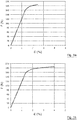
- the force (F (in N)) Elongation (in %) curve of the wire is depicted in Figure 1a .
- the wire has a diameter of 0.295 mm, a breaking load of 184 N - hence a tensile strength of 2692 N/mm 2 i.e. Normal Tensile class- and shows an elongation at break of 2.5%. It follows that the E-ratios of both reinforcement layers are equal to 107 689 N/mm 2 .
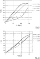
- Figure 2 shows the resulting force (F (in N) in ordinate) on the wires of the inner layer (full line) and outer layer (dashed line) when the hose is pressurised (P (in MPa) in abscissa).
- the steel wires of the innermost reinforcement layer have been thermally treated while the steel wires of the outermost reinforcement layer are left unaltered i.e. as drawn with the same force elongation diagram as of Figure 1a .
- the plastic region of the wire is greatly increased together with a loss in tensile strength.
- a wire with a tensile strength of about 2700 N/mm 2 one must therefore depart from a wire having a tensile strength of about 3100 N/mm 2 .
- the force - elongation diagram of a thermally altered steel wire is shown in Figure 1b .
- the wire has an elongation at break of 4% while it attains a tensile strength of 2700 N/mm 2 . Hence its E-ratio is 67500 MPa i.e. much lower than that of the unaltered wire. This wire is used for the innermost reinforcement layer.
- Figure 3 shows again the forces occurring in the wires of the reinforcement layers (F (in N)) as a function of the pressure 'P' (in MPa) .
- the full line is for the wires in the innermost reinforcement layer while the dashed line refers to the forces occurring in the outermost reinforcement layer. Due to the much higher elongation at break of the first layer it does not break prematurely and maintains it strength till much higher pressures.
- the burst pressure now occurs at 160 MPa and all wires are practically loaded to their tensile strength. Compared to the conventional hose, the burst pressure has increased with 14%. However, when comparing the forces occurring in the wires at about one fourth of the burst pressure i.e.
- the steel wires of the innermost reinforcement layer were subjected to a crimping treatment.
- the untreated wire (with the load - elongation according Figure 1a ) was drawn through a pair of crimping wheels thereby giving the wire a wave-like shape with an amplitude 'a' and a wavelength ' ⁇ '.
- 'double amplitude 2a' is meant the distance between parallel planes touching the extreme tops of the crimped wire minus the diameter of the wire. It can be shown that the extra elongation due to the 'structure of the wire ' i.e. the deformation of the wire ⁇ structural scales according: ⁇ structural ⁇ a / ⁇ 2
- the wire had received a crimp of wavelength 5.3 mm with amplitude 'a' of 0.238 mm. This resulted in an extra elongation of about 2% giving a total elongation at break of 4.5%.
- the breaking load only slightly decreased to 178 N.
- the tensile strength was 2600 MPa resulting in an E-ratio of 57 873 MPa which is well below the original 107 689 MPa value of the original wire by a factor of 0.537.
- a second steel wire of 0.30 mm diameter originally had a breaking load of 183N resulting in a tensile strength of 2590 N/mm 2 (Normal Tensile strength).
- the elongation at break was 2.3%.
- the breaking load was 172N at an elongation of break of 3.0% i.e. an increase of elongation of 0.7%.
- the original E-ratio of 113 000 N/mm 2 decreased to 81 000 N/mm 2 or a factor of 0.717 by the crimping.
- Figures 5 and 6 show devices 500, 600 with which unidirectional bends or bidirectional crimps can be imposed on the wire.
- a device can be easily mounted on the spool carrier of the braiding machine or on the winding head of a spiralling machine.
- a preforming pin 506, 606 is already present in order to give the steel wires a helical deformation that fits the winding angle of the reinforcement layer.
- the preforming device can be used off-line i.e. during rewinding of the steel wires on the braiding or spiralling machine bobbins, or can be used in-line i.e. the wires are deformed concurrently with the winding of the wires around the hose body.
- wires 504 coming from the pay-off spool in parallel are first guided over the preforming pin 506.
- Preforming pin 506 can either be fixedly or rotatably connected to mounting plate 502.
- the imposed radius of curvature will - amongst others - depend on diameter and tensile strength of the wires and the diameter and friction properties (if non-rotatable) of the preforming pin 506.
- the wires are thereafter guided over a polygonal shaped wheel 508 that is mounted rotatable on axis 512.
- the wheel can be provided with teeth 510. If sufficient tension is maintained on the steel wires, the steel wires 504' leaving the preforming device will show very local and very small bends 514.
- the bends are always in the same direction (unidirectional). Bends of different wires are 'in phase' when leaving the polygonal shaped wheel i.e. the bends occur at equal positions along parallel wires. The wires are subsequently wound around the intermediate hose body (not shown).
- wires 604 coming from the pay-off spool in parallel are again first guided over a performer pin 606 that may be rotating or fixed.
- the wires are subsequently led between two preforming wheels 608 and 618 that are provided with intermeshing teeth 616, 610.
- the wheels are mounted rotatable on axes 620, 612 to the mounting plate 602.
- the wheels are sufficiently far apart that the wires 604 can pass without damage.
- the deformed wires 604' are wound around the then already formed intermediate hose body (not shown).
- the passage through the forming wheels gives the wires a bidirectional, zig-zag like crimp 614.
- the amplitude of the crimp can be set by the distance between the preforming wheels and the wavelength of the crimp can be set by changing the pitch module of the teeth. Again the crimps are 'in phase'.
- Figures 7 to 10 illustrate what happens when the inventive concept is applied to a high pressure hose of spiralled build-up with four reinforcement layers that are numbered L1 to L4 from radially most inner to most outer layer as summarised in Table II.
- the inner diameter of the hose (32 mm) is considerably larger than for the braided hose (9.52 mm) and therefore the reinforcement wall must be much stronger to guarantee about the same working pressure of 36 MPa.
- the spiralled hose has four steel wire reinforcement layers, situated at four discrete radii.
- the steel wires are wound in alternating directions (S, Z, S, Z) under slightly increasing winding angles - all close to the neutral angle - when progressing from the inner reinforcement layer to the outer reinforcement layer as is customarily in the field.
- the wires are of diameter 0.60 mm in all embodiments following:
- the steel wires of the inner layers L1 and L2 are replaced with steel wires with bends by guiding conventional 0.60 mm wires under tension over a polygonal wheel.
- the bends increase the elongation at break of the wire from 2.5% up to 4.5% with only a small decrease in breaking load: from 820 N to 778 N.
- the E-ratio of the steel wire reduces from 116 000 N/mm 2 (conventional wires) to 61147 N/mm 2 .
- the bends are outwardly oriented relative to the axis of the hose.
- the outer two layers L3 and L4 are made of conventional wires.
Landscapes
- Engineering & Computer Science (AREA)
- General Engineering & Computer Science (AREA)
- Mechanical Engineering (AREA)
- Rigid Pipes And Flexible Pipes (AREA)
- Laminated Bodies (AREA)
Claims (9)
- Schlauch zum Transportieren von Flüssigkeiten unter Druck, umfassend einen Elastomerkernschlauch, mindestens zwei Verstärkungsschichten an getrennten Verstärkungsschichtradien, wobei die Verstärkungsschichten durch intermediäre Elastomermaterialschichten radial voneinander getrennt sind und eine äußere Schutzschicht die äußerste Verstärkungsschicht bedeckt, wobei mindestens zwei der Verstärkungsschichten Stahldrähte umfassen, die spiralförmig um die Achse des Schlauchs gewickelt sind, wobei die Stahldrähte der radial äußersten Stahldrahtverstärkungsschicht das höchste E-Verhältnis aufweisen, wobei die Stahldrähte der innersten Stahldrahtverstärkungsschicht das niedrigste E-Verhältnis, das sich vom höchsten E-Verhältnis unterscheidet, aufweisen, wobei das E-Verhältnis einer beliebigen Stahldrahtverstärkungsschicht nicht niedriger als das E-Verhältnis einer beliebigen innenliegenden Stahlverstärkungsschicht ist, wobei das E-Verhältnis dem Verhältnis der Zugfestigkeit über die Bruchdehnung des Stahldrahts gleicht, wobei das E-Verhältnis zwischen 70 000 N/mm2 und bis zu 200 000 N/mm2 für die radial äußerste Stahldrahtverstärkungsschicht und zwischen 30 000 N/mm2 und 120 000 N/mm2 für die radial innerste Stahldrahtverstärkungsschicht beträgt,
dadurch gekennzeichnet, dass
die Stahldrähte mindestens der innersten Stahldrahtverstärkungsschicht Faltungen innerhalb einer einzelnen Ebene aufweisen oder Biegungen aufweisen, wobei die Faltungen oder Biegungen der Veränderung des ursprünglichen E-Verhältnisses und dem Erhalt des E-Verhältnisses dienen, während die Stahldrähte mindestens der äußersten Stahldrahtverstärkungsschicht keine Biegungen oder Faltungen aufweisen. - Schlauch nach Anspruch 1, wobei die Bruchdehnung der Stahldrähte mindestens der innersten Stahldrahtverstärkungsschicht durch die Faltungen oder Biegungen im Stahldraht im Vergleich zu dem Stahldraht, der keine Faltungen oder Biegungen aufweist, um mindestens 0,3% höher ist.
- Schlauch nach einem der Ansprüche 1 bis 2, wobei die Stahldrähte mindestens der innersten und äußersten Stahldrahtverstärkungsschicht denselben Durchmesser aufweisen.
- Schlauch nach einem der Ansprüche 1 bis 3, wobei die Stahldrähte mindestens der innersten und äußersten Stahldrahtverstärkungsschicht zur gleichen Zugklasse gehören.
- Schlauch nach einem der Ansprüche 1 bis 4, wobei die Stahldrähte mindestens in der innersten Stahldrahtverstärkungsschicht in regelmäßigen Abständen unidirektional gebogen sind, um das E-Verhältnis der Stahldrahtverstärkungsschicht zu reduzieren.
- Schlauch nach einem der Ansprüche 1 bis 4, wobei die Stahldrähte mindestens in der innersten Stahldrahtverstärkungsschicht in regelmäßigen Abständen bidirektional gekräuselt sind, um das E-Verhältnis der Stahldrahtverstärkungsschicht zu reduzieren.
- Verfahren zur Herstellung eines Schlauchs zum Transportieren von Flüssigkeiten unter hohem Druck nach einem der Ansprüche 1 bis 6, umfassend die folgenden Schritte:- Bereitstellen eines Elastomerkernschlauchs;- Wickeln von Stahldrähten um den Elastomerkernschlauch in einer spiralförmigen oder geflochtenen innersten Stahldrahtverstärkungsschicht;- Aufbringen einer intermediären Elastomermaterialschicht auf die innerste Stahldrahtverstärkungsschicht;- Wickeln einer weiteren spiralförmigen oder geflochtenen Stahldrahtverstärkungsschicht auf die intermediäre Elastomermaterialschicht;- fakultatives Aufbringen einer intermediären Elastomermaterialschicht auf die äußerste Stahldrahtverstärkungsschicht;- fakultatives Aufbringen einer weiteren spiralförmigen oder geflochtenen Stahldrahtverstärkungsschicht auf die intermediäre Elastomermaterialschicht;- fakultatives ein- oder mehrmaliges Wiederholen der zwei vorherigen Schritte;- Aufbringen einer äußeren Schutzschicht, die die äußerste Verstärkungsschicht bedeckt;wobei die Stahldrähte der innersten Stahldrahtverstärkungsschicht ein E-Verhältnis aufweisen, das niedriger als das E-Verhältnis der Stahldrähte der radial äußersten Stahldrahtverstärkungsschicht ist, wobei das E-Verhältnis einer beliebigen Stahldrahtverstärkungsschicht nicht niedriger als das E-Verhältnis einer beliebigen innenliegenden Stahldrahtverstärkungsschicht ist,
dadurch gekennzeichnet, dass
die Stahldrähte mindestens der innersten Stahldrahtverstärkungsschicht mit einer Vorformungsvorrichtung vorgeformt werden, die Faltungen oder Biegungen in den Stahldrähten auslöst, gleichzeitig mit dem Schritt des Wickelns von Stahldrähten mindestens in der innersten Stahldrahtverstärkungsschicht. - Verfahren nach Anspruch 7, wobei die Vorformungsvorrichtung einen drehbaren Stift mit einer im Wesentlichen polygonalen Gestalt umfasst, über den die Stahldrähte unter Spannung geführt werden, wodurch in regelmäßigen Abständen unidirektionale Biegungen auf den Stahldrähten ausgelöst werden.
- Verfahren nach Anspruch 7, wobei die Vorformungsvorrichtung ein Paar in Eingriff stehender Zahnräder umfasst, zwischen denen die Stahldrähte geführt werden, wodurch in regelmäßigen Abständen bidirektionale Faltungen in den Drähten ausgelöst werden.
Priority Applications (2)
| Application Number | Priority Date | Filing Date | Title |
|---|---|---|---|
| PL14733170T PL3017226T3 (pl) | 2013-07-04 | 2014-06-26 | Wąż ze zoptymalizowanymi warstwami wzmocnienia drutem stalowym |
| EP14733170.6A EP3017226B1 (de) | 2013-07-04 | 2014-06-26 | Schlauch mit optimierten stahldrahtverstärkungsschichten |
Applications Claiming Priority (3)
| Application Number | Priority Date | Filing Date | Title |
|---|---|---|---|
| EP13175073 | 2013-07-04 | ||
| PCT/EP2014/063471 WO2015000773A1 (en) | 2013-07-04 | 2014-06-26 | Hose with optimised steel wire reinforcement layers |
| EP14733170.6A EP3017226B1 (de) | 2013-07-04 | 2014-06-26 | Schlauch mit optimierten stahldrahtverstärkungsschichten |
Publications (2)
| Publication Number | Publication Date |
|---|---|
| EP3017226A1 EP3017226A1 (de) | 2016-05-11 |
| EP3017226B1 true EP3017226B1 (de) | 2020-11-04 |
Family
ID=48782198
Family Applications (1)
| Application Number | Title | Priority Date | Filing Date |
|---|---|---|---|
| EP14733170.6A Active EP3017226B1 (de) | 2013-07-04 | 2014-06-26 | Schlauch mit optimierten stahldrahtverstärkungsschichten |
Country Status (9)
| Country | Link |
|---|---|
| US (1) | US10189225B2 (de) |
| EP (1) | EP3017226B1 (de) |
| KR (1) | KR102217006B1 (de) |
| CN (1) | CN105358888B (de) |
| EA (1) | EA029663B1 (de) |
| HU (1) | HUE052015T2 (de) |
| MY (1) | MY176590A (de) |
| PL (1) | PL3017226T3 (de) |
| WO (1) | WO2015000773A1 (de) |
Families Citing this family (7)
| Publication number | Priority date | Publication date | Assignee | Title |
|---|---|---|---|---|
| MY189193A (en) | 2015-07-08 | 2022-01-31 | Bekaert Sa Nv | Strip for reinforcement of a hose and a method of manufacture thereof |
| WO2017157877A1 (en) * | 2016-03-15 | 2017-09-21 | Nv Bekaert Sa | Hose reinforcement wire with increased formability |
| JP6988159B2 (ja) * | 2017-05-16 | 2022-01-05 | 横浜ゴム株式会社 | 高圧ホース |
| CN108804837A (zh) * | 2018-06-15 | 2018-11-13 | 中国石油大学(华东) | 一种基于有限元的高压胶管结构优化设计方法 |
| RU209355U1 (ru) * | 2021-11-02 | 2022-03-15 | Сергей Гаевич Степанов | Гибкий рукав |
| KR20230140907A (ko) | 2022-03-30 | 2023-10-10 | (유)씨앤투영 | 하이브리드 보강층을 갖는 고압호스 |
| WO2025187178A1 (ja) * | 2024-03-08 | 2025-09-12 | 株式会社ブリヂストン | ホース |
Family Cites Families (10)
| Publication number | Priority date | Publication date | Assignee | Title |
|---|---|---|---|---|
| US4273160A (en) | 1977-09-12 | 1981-06-16 | Parker-Hannifin Corporation | High pressure hose |
| US4585035A (en) * | 1983-12-19 | 1986-04-29 | The Goodyear Tire & Rubber Company | Reinforced hose |
| LU85874A1 (fr) * | 1985-04-29 | 1986-11-05 | Bekaert Sa Nv | Procede de fabrication de tuyau a haute resistance a la pression et a la fatigue et tuyau ainsi obtenu |
| KR100367116B1 (ko) | 1993-12-15 | 2003-02-25 | 엔.브이. 베카에르트 에스.에이. | 개방구조의스틸코드및그것의제조방법 |
| ZA9810315B (en) * | 1997-11-27 | 1999-05-18 | Bekaert Sa Nv | Steel cord with spatially waved elements |
| WO2002050464A1 (en) | 2000-12-20 | 2002-06-27 | N.V. Bekaert S.A. | Flexibile duct reinforced with high-tensile steel members |
| WO2004065686A1 (ja) * | 2003-01-24 | 2004-08-05 | The Yokohama Rubber Co., Ltd. | ゴム用補強材、該補強材を用いたゴム製品及びその製造方法、並びに、該補強材を用いた空気入りタイヤ及びその製造方法 |
| JP4859349B2 (ja) | 2004-04-05 | 2012-01-25 | 横浜ゴム株式会社 | ホース |
| EP1596114A1 (de) | 2004-05-12 | 2005-11-16 | N.V. Bekaert S.A. | Flachkabel mit hoher Zugfestigkeit für Verstärkung der Schläuche |
| US7328725B2 (en) * | 2005-08-15 | 2008-02-12 | Eaton Corporation | Reinforced hose |
-
2014
- 2014-06-26 EP EP14733170.6A patent/EP3017226B1/de active Active
- 2014-06-26 KR KR1020157036870A patent/KR102217006B1/ko not_active Expired - Fee Related
- 2014-06-26 MY MYPI2015704819A patent/MY176590A/en unknown
- 2014-06-26 HU HUE14733170A patent/HUE052015T2/hu unknown
- 2014-06-26 US US14/898,419 patent/US10189225B2/en active Active
- 2014-06-26 WO PCT/EP2014/063471 patent/WO2015000773A1/en not_active Ceased
- 2014-06-26 PL PL14733170T patent/PL3017226T3/pl unknown
- 2014-06-26 CN CN201480038666.4A patent/CN105358888B/zh active Active
- 2014-06-26 EA EA201690163A patent/EA029663B1/ru not_active IP Right Cessation
Non-Patent Citations (1)
| Title |
|---|
| None * |
Also Published As
| Publication number | Publication date |
|---|---|
| CN105358888A (zh) | 2016-02-24 |
| PL3017226T3 (pl) | 2021-04-19 |
| MY176590A (en) | 2020-08-18 |
| CN105358888B (zh) | 2018-07-31 |
| US20160136918A1 (en) | 2016-05-19 |
| EP3017226A1 (de) | 2016-05-11 |
| KR20160028419A (ko) | 2016-03-11 |
| KR102217006B1 (ko) | 2021-02-22 |
| EA201690163A1 (ru) | 2016-05-31 |
| EA029663B1 (ru) | 2018-04-30 |
| US10189225B2 (en) | 2019-01-29 |
| WO2015000773A1 (en) | 2015-01-08 |
| HUE052015T2 (hu) | 2021-04-28 |
Similar Documents
| Publication | Publication Date | Title |
|---|---|---|
| US10189225B2 (en) | Hose with optimized steel wire reinforcement layers | |
| US6109306A (en) | Kink-resistant, high pressure hose construction having a composite, spiral wound innermost reinforcement layer | |
| KR100431373B1 (ko) | 스틸코오드 및 이것을 사용한 공기타이어 | |
| AU2007246823B2 (en) | Improvements relating to hose | |
| JP5623425B2 (ja) | タイヤ補強用鋼コード | |
| KR102653649B1 (ko) | 폴리머 물품의 보강을 위한 보강 스트랜드 | |
| AU2014252857A1 (en) | A flexible pipe body and method of manufacture | |
| US11614182B2 (en) | Reinforcement layer | |
| EP0969236A2 (de) | Knickbeständiger Hochdruckschlauch | |
| WO2013073433A1 (ja) | 積層補強ホース | |
| EP2796274B1 (de) | Flacher draht | |
| CN114811207B (zh) | 软管用金属线的规格决定方法及软管 | |
| EP2807400B1 (de) | Seilstrumpf mit flachen oder abgeflachten fasern |
Legal Events
| Date | Code | Title | Description |
|---|---|---|---|
| PUAI | Public reference made under article 153(3) epc to a published international application that has entered the european phase |
Free format text: ORIGINAL CODE: 0009012 |
|
| 17P | Request for examination filed |
Effective date: 20151203 |
|
| AK | Designated contracting states |
Kind code of ref document: A1 Designated state(s): AL AT BE BG CH CY CZ DE DK EE ES FI FR GB GR HR HU IE IS IT LI LT LU LV MC MK MT NL NO PL PT RO RS SE SI SK SM TR |
|
| AX | Request for extension of the european patent |
Extension state: BA ME |
|
| DAX | Request for extension of the european patent (deleted) | ||
| STAA | Information on the status of an ep patent application or granted ep patent |
Free format text: STATUS: EXAMINATION IS IN PROGRESS |
|
| 17Q | First examination report despatched |
Effective date: 20190503 |
|
| GRAP | Despatch of communication of intention to grant a patent |
Free format text: ORIGINAL CODE: EPIDOSNIGR1 |
|
| STAA | Information on the status of an ep patent application or granted ep patent |
Free format text: STATUS: GRANT OF PATENT IS INTENDED |
|
| INTG | Intention to grant announced |
Effective date: 20200615 |
|
| RIN1 | Information on inventor provided before grant (corrected) |
Inventor name: VANDENBROUCKE, BEN Inventor name: GALLE, PETER |
|
| GRAS | Grant fee paid |
Free format text: ORIGINAL CODE: EPIDOSNIGR3 |
|
| GRAA | (expected) grant |
Free format text: ORIGINAL CODE: 0009210 |
|
| STAA | Information on the status of an ep patent application or granted ep patent |
Free format text: STATUS: THE PATENT HAS BEEN GRANTED |
|
| AK | Designated contracting states |
Kind code of ref document: B1 Designated state(s): AL AT BE BG CH CY CZ DE DK EE ES FI FR GB GR HR HU IE IS IT LI LT LU LV MC MK MT NL NO PL PT RO RS SE SI SK SM TR |
|
| REG | Reference to a national code |
Ref country code: GB Ref legal event code: FG4D |
|
| REG | Reference to a national code |
Ref country code: CH Ref legal event code: EP |
|
| REG | Reference to a national code |
Ref country code: AT Ref legal event code: REF Ref document number: 1331276 Country of ref document: AT Kind code of ref document: T Effective date: 20201115 |
|
| REG | Reference to a national code |
Ref country code: DE Ref legal event code: R096 Ref document number: 602014071969 Country of ref document: DE |
|
| REG | Reference to a national code |
Ref country code: IE Ref legal event code: FG4D |
|
| REG | Reference to a national code |
Ref country code: RO Ref legal event code: EPE |
|
| REG | Reference to a national code |
Ref country code: NL Ref legal event code: MP Effective date: 20201104 |
|
| REG | Reference to a national code |
Ref country code: HU Ref legal event code: AG4A Ref document number: E052015 Country of ref document: HU |
|
| PG25 | Lapsed in a contracting state [announced via postgrant information from national office to epo] |
Ref country code: PT Free format text: LAPSE BECAUSE OF FAILURE TO SUBMIT A TRANSLATION OF THE DESCRIPTION OR TO PAY THE FEE WITHIN THE PRESCRIBED TIME-LIMIT Effective date: 20210304 Ref country code: NO Free format text: LAPSE BECAUSE OF FAILURE TO SUBMIT A TRANSLATION OF THE DESCRIPTION OR TO PAY THE FEE WITHIN THE PRESCRIBED TIME-LIMIT Effective date: 20210204 Ref country code: RS Free format text: LAPSE BECAUSE OF FAILURE TO SUBMIT A TRANSLATION OF THE DESCRIPTION OR TO PAY THE FEE WITHIN THE PRESCRIBED TIME-LIMIT Effective date: 20201104 Ref country code: FI Free format text: LAPSE BECAUSE OF FAILURE TO SUBMIT A TRANSLATION OF THE DESCRIPTION OR TO PAY THE FEE WITHIN THE PRESCRIBED TIME-LIMIT Effective date: 20201104 Ref country code: GR Free format text: LAPSE BECAUSE OF FAILURE TO SUBMIT A TRANSLATION OF THE DESCRIPTION OR TO PAY THE FEE WITHIN THE PRESCRIBED TIME-LIMIT Effective date: 20210205 |
|
| PG25 | Lapsed in a contracting state [announced via postgrant information from national office to epo] |
Ref country code: IS Free format text: LAPSE BECAUSE OF FAILURE TO SUBMIT A TRANSLATION OF THE DESCRIPTION OR TO PAY THE FEE WITHIN THE PRESCRIBED TIME-LIMIT Effective date: 20210304 Ref country code: LV Free format text: LAPSE BECAUSE OF FAILURE TO SUBMIT A TRANSLATION OF THE DESCRIPTION OR TO PAY THE FEE WITHIN THE PRESCRIBED TIME-LIMIT Effective date: 20201104 Ref country code: SE Free format text: LAPSE BECAUSE OF FAILURE TO SUBMIT A TRANSLATION OF THE DESCRIPTION OR TO PAY THE FEE WITHIN THE PRESCRIBED TIME-LIMIT Effective date: 20201104 Ref country code: ES Free format text: LAPSE BECAUSE OF FAILURE TO SUBMIT A TRANSLATION OF THE DESCRIPTION OR TO PAY THE FEE WITHIN THE PRESCRIBED TIME-LIMIT Effective date: 20201104 Ref country code: BG Free format text: LAPSE BECAUSE OF FAILURE TO SUBMIT A TRANSLATION OF THE DESCRIPTION OR TO PAY THE FEE WITHIN THE PRESCRIBED TIME-LIMIT Effective date: 20210204 |
|
| REG | Reference to a national code |
Ref country code: LT Ref legal event code: MG9D |
|
| PG25 | Lapsed in a contracting state [announced via postgrant information from national office to epo] |
Ref country code: HR Free format text: LAPSE BECAUSE OF FAILURE TO SUBMIT A TRANSLATION OF THE DESCRIPTION OR TO PAY THE FEE WITHIN THE PRESCRIBED TIME-LIMIT Effective date: 20201104 |
|
| PG25 | Lapsed in a contracting state [announced via postgrant information from national office to epo] |
Ref country code: LT Free format text: LAPSE BECAUSE OF FAILURE TO SUBMIT A TRANSLATION OF THE DESCRIPTION OR TO PAY THE FEE WITHIN THE PRESCRIBED TIME-LIMIT Effective date: 20201104 Ref country code: SK Free format text: LAPSE BECAUSE OF FAILURE TO SUBMIT A TRANSLATION OF THE DESCRIPTION OR TO PAY THE FEE WITHIN THE PRESCRIBED TIME-LIMIT Effective date: 20201104 Ref country code: EE Free format text: LAPSE BECAUSE OF FAILURE TO SUBMIT A TRANSLATION OF THE DESCRIPTION OR TO PAY THE FEE WITHIN THE PRESCRIBED TIME-LIMIT Effective date: 20201104 Ref country code: SM Free format text: LAPSE BECAUSE OF FAILURE TO SUBMIT A TRANSLATION OF THE DESCRIPTION OR TO PAY THE FEE WITHIN THE PRESCRIBED TIME-LIMIT Effective date: 20201104 |
|
| REG | Reference to a national code |
Ref country code: DE Ref legal event code: R097 Ref document number: 602014071969 Country of ref document: DE |
|
| REG | Reference to a national code |
Ref country code: AT Ref legal event code: UEP Ref document number: 1331276 Country of ref document: AT Kind code of ref document: T Effective date: 20201104 |
|
| PG25 | Lapsed in a contracting state [announced via postgrant information from national office to epo] |
Ref country code: DK Free format text: LAPSE BECAUSE OF FAILURE TO SUBMIT A TRANSLATION OF THE DESCRIPTION OR TO PAY THE FEE WITHIN THE PRESCRIBED TIME-LIMIT Effective date: 20201104 |
|
| PLBE | No opposition filed within time limit |
Free format text: ORIGINAL CODE: 0009261 |
|
| STAA | Information on the status of an ep patent application or granted ep patent |
Free format text: STATUS: NO OPPOSITION FILED WITHIN TIME LIMIT |
|
| 26N | No opposition filed |
Effective date: 20210805 |
|
| PG25 | Lapsed in a contracting state [announced via postgrant information from national office to epo] |
Ref country code: NL Free format text: LAPSE BECAUSE OF FAILURE TO SUBMIT A TRANSLATION OF THE DESCRIPTION OR TO PAY THE FEE WITHIN THE PRESCRIBED TIME-LIMIT Effective date: 20201104 Ref country code: AL Free format text: LAPSE BECAUSE OF FAILURE TO SUBMIT A TRANSLATION OF THE DESCRIPTION OR TO PAY THE FEE WITHIN THE PRESCRIBED TIME-LIMIT Effective date: 20201104 |
|
| PG25 | Lapsed in a contracting state [announced via postgrant information from national office to epo] |
Ref country code: SI Free format text: LAPSE BECAUSE OF FAILURE TO SUBMIT A TRANSLATION OF THE DESCRIPTION OR TO PAY THE FEE WITHIN THE PRESCRIBED TIME-LIMIT Effective date: 20201104 |
|
| PG25 | Lapsed in a contracting state [announced via postgrant information from national office to epo] |
Ref country code: MC Free format text: LAPSE BECAUSE OF FAILURE TO SUBMIT A TRANSLATION OF THE DESCRIPTION OR TO PAY THE FEE WITHIN THE PRESCRIBED TIME-LIMIT Effective date: 20201104 |
|
| REG | Reference to a national code |
Ref country code: CH Ref legal event code: PL |
|
| REG | Reference to a national code |
Ref country code: BE Ref legal event code: MM Effective date: 20210630 |
|
| PG25 | Lapsed in a contracting state [announced via postgrant information from national office to epo] |
Ref country code: LU Free format text: LAPSE BECAUSE OF NON-PAYMENT OF DUE FEES Effective date: 20210626 |
|
| PG25 | Lapsed in a contracting state [announced via postgrant information from national office to epo] |
Ref country code: LI Free format text: LAPSE BECAUSE OF NON-PAYMENT OF DUE FEES Effective date: 20210630 Ref country code: IE Free format text: LAPSE BECAUSE OF NON-PAYMENT OF DUE FEES Effective date: 20210626 Ref country code: CH Free format text: LAPSE BECAUSE OF NON-PAYMENT OF DUE FEES Effective date: 20210630 |
|
| PG25 | Lapsed in a contracting state [announced via postgrant information from national office to epo] |
Ref country code: IS Free format text: LAPSE BECAUSE OF FAILURE TO SUBMIT A TRANSLATION OF THE DESCRIPTION OR TO PAY THE FEE WITHIN THE PRESCRIBED TIME-LIMIT Effective date: 20210304 |
|
| PG25 | Lapsed in a contracting state [announced via postgrant information from national office to epo] |
Ref country code: BE Free format text: LAPSE BECAUSE OF NON-PAYMENT OF DUE FEES Effective date: 20210630 |
|
| PGFP | Annual fee paid to national office [announced via postgrant information from national office to epo] |
Ref country code: HU Payment date: 20220617 Year of fee payment: 9 Ref country code: GB Payment date: 20220627 Year of fee payment: 9 Ref country code: RO Payment date: 20220616 Year of fee payment: 9 |
|
| PGFP | Annual fee paid to national office [announced via postgrant information from national office to epo] |
Ref country code: FR Payment date: 20220628 Year of fee payment: 9 |
|
| PG25 | Lapsed in a contracting state [announced via postgrant information from national office to epo] |
Ref country code: CY Free format text: LAPSE BECAUSE OF FAILURE TO SUBMIT A TRANSLATION OF THE DESCRIPTION OR TO PAY THE FEE WITHIN THE PRESCRIBED TIME-LIMIT Effective date: 20201104 |
|
| P01 | Opt-out of the competence of the unified patent court (upc) registered |
Effective date: 20230619 |
|
| PG25 | Lapsed in a contracting state [announced via postgrant information from national office to epo] |
Ref country code: RO Free format text: LAPSE BECAUSE OF NON-PAYMENT OF DUE FEES Effective date: 20230626 |
|
| GBPC | Gb: european patent ceased through non-payment of renewal fee |
Effective date: 20230626 |
|
| PG25 | Lapsed in a contracting state [announced via postgrant information from national office to epo] |
Ref country code: HU Free format text: LAPSE BECAUSE OF NON-PAYMENT OF DUE FEES Effective date: 20230627 Ref country code: GB Free format text: LAPSE BECAUSE OF NON-PAYMENT OF DUE FEES Effective date: 20230626 |
|
| PG25 | Lapsed in a contracting state [announced via postgrant information from national office to epo] |
Ref country code: FR Free format text: LAPSE BECAUSE OF NON-PAYMENT OF DUE FEES Effective date: 20230630 |
|
| PGFP | Annual fee paid to national office [announced via postgrant information from national office to epo] |
Ref country code: CZ Payment date: 20240614 Year of fee payment: 11 |
|
| PG25 | Lapsed in a contracting state [announced via postgrant information from national office to epo] |
Ref country code: MT Free format text: LAPSE BECAUSE OF FAILURE TO SUBMIT A TRANSLATION OF THE DESCRIPTION OR TO PAY THE FEE WITHIN THE PRESCRIBED TIME-LIMIT Effective date: 20201104 |
|
| PGFP | Annual fee paid to national office [announced via postgrant information from national office to epo] |
Ref country code: PL Payment date: 20250613 Year of fee payment: 12 Ref country code: DE Payment date: 20250618 Year of fee payment: 12 |
|
| PGFP | Annual fee paid to national office [announced via postgrant information from national office to epo] |
Ref country code: AT Payment date: 20250620 Year of fee payment: 12 |
|
| PGFP | Annual fee paid to national office [announced via postgrant information from national office to epo] |
Ref country code: TR Payment date: 20250617 Year of fee payment: 12 |
|
| PGFP | Annual fee paid to national office [announced via postgrant information from national office to epo] |
Ref country code: IT Payment date: 20250624 Year of fee payment: 12 |
|
| PG25 | Lapsed in a contracting state [announced via postgrant information from national office to epo] |
Ref country code: CZ Free format text: LAPSE BECAUSE OF NON-PAYMENT OF DUE FEES Effective date: 20250626 |