EP3017227B1 - Agencement de liaison de tube, système de conduites de fluide haute pression d'un moteur à combustion interne dualfuel, moteur à combustion interne dualfuel et utilisation d'un écrou de serrage - Google Patents
Agencement de liaison de tube, système de conduites de fluide haute pression d'un moteur à combustion interne dualfuel, moteur à combustion interne dualfuel et utilisation d'un écrou de serrage Download PDFInfo
- Publication number
- EP3017227B1 EP3017227B1 EP14758818.0A EP14758818A EP3017227B1 EP 3017227 B1 EP3017227 B1 EP 3017227B1 EP 14758818 A EP14758818 A EP 14758818A EP 3017227 B1 EP3017227 B1 EP 3017227B1
- Authority
- EP
- European Patent Office
- Prior art keywords
- pipe
- connection arrangement
- pipe connection
- cone
- threaded sleeve
- Prior art date
- Legal status (The legal status is an assumption and is not a legal conclusion. Google has not performed a legal analysis and makes no representation as to the accuracy of the status listed.)
- Active
Links
Images
Classifications
-
- F—MECHANICAL ENGINEERING; LIGHTING; HEATING; WEAPONS; BLASTING
- F16—ENGINEERING ELEMENTS AND UNITS; GENERAL MEASURES FOR PRODUCING AND MAINTAINING EFFECTIVE FUNCTIONING OF MACHINES OR INSTALLATIONS; THERMAL INSULATION IN GENERAL
- F16L—PIPES; JOINTS OR FITTINGS FOR PIPES; SUPPORTS FOR PIPES, CABLES OR PROTECTIVE TUBING; MEANS FOR THERMAL INSULATION IN GENERAL
- F16L19/00—Joints in which sealing surfaces are pressed together by means of a member, e.g. a swivel nut, screwed on, or into, one of the joint parts
- F16L19/02—Pipe ends provided with collars or flanges, integral with the pipe or not, pressed together by a screwed member
- F16L19/025—Pipe ends provided with collars or flanges, integral with the pipe or not, pressed together by a screwed member the pipe ends having integral collars or flanges
-
- F—MECHANICAL ENGINEERING; LIGHTING; HEATING; WEAPONS; BLASTING
- F02—COMBUSTION ENGINES; HOT-GAS OR COMBUSTION-PRODUCT ENGINE PLANTS
- F02C—GAS-TURBINE PLANTS; AIR INTAKES FOR JET-PROPULSION PLANTS; CONTROLLING FUEL SUPPLY IN AIR-BREATHING JET-PROPULSION PLANTS
- F02C7/00—Features, components parts, details or accessories, not provided for in, or of interest apart form groups F02C1/00 - F02C6/00; Air intakes for jet-propulsion plants
- F02C7/22—Fuel supply systems
- F02C7/222—Fuel flow conduits, e.g. manifolds
-
- F—MECHANICAL ENGINEERING; LIGHTING; HEATING; WEAPONS; BLASTING
- F02—COMBUSTION ENGINES; HOT-GAS OR COMBUSTION-PRODUCT ENGINE PLANTS
- F02C—GAS-TURBINE PLANTS; AIR INTAKES FOR JET-PROPULSION PLANTS; CONTROLLING FUEL SUPPLY IN AIR-BREATHING JET-PROPULSION PLANTS
- F02C9/00—Controlling gas-turbine plants; Controlling fuel supply in air- breathing jet-propulsion plants
- F02C9/26—Control of fuel supply
- F02C9/40—Control of fuel supply specially adapted to the use of a special fuel or a plurality of fuels
-
- F—MECHANICAL ENGINEERING; LIGHTING; HEATING; WEAPONS; BLASTING
- F16—ENGINEERING ELEMENTS AND UNITS; GENERAL MEASURES FOR PRODUCING AND MAINTAINING EFFECTIVE FUNCTIONING OF MACHINES OR INSTALLATIONS; THERMAL INSULATION IN GENERAL
- F16L—PIPES; JOINTS OR FITTINGS FOR PIPES; SUPPORTS FOR PIPES, CABLES OR PROTECTIVE TUBING; MEANS FOR THERMAL INSULATION IN GENERAL
- F16L19/00—Joints in which sealing surfaces are pressed together by means of a member, e.g. a swivel nut, screwed on, or into, one of the joint parts
- F16L19/02—Pipe ends provided with collars or flanges, integral with the pipe or not, pressed together by a screwed member
- F16L19/0212—Pipe ends provided with collars or flanges, integral with the pipe or not, pressed together by a screwed member using specially adapted sealing means
-
- F—MECHANICAL ENGINEERING; LIGHTING; HEATING; WEAPONS; BLASTING
- F16—ENGINEERING ELEMENTS AND UNITS; GENERAL MEASURES FOR PRODUCING AND MAINTAINING EFFECTIVE FUNCTIONING OF MACHINES OR INSTALLATIONS; THERMAL INSULATION IN GENERAL
- F16L—PIPES; JOINTS OR FITTINGS FOR PIPES; SUPPORTS FOR PIPES, CABLES OR PROTECTIVE TUBING; MEANS FOR THERMAL INSULATION IN GENERAL
- F16L51/00—Expansion-compensation arrangements for pipe-lines
-
- F—MECHANICAL ENGINEERING; LIGHTING; HEATING; WEAPONS; BLASTING
- F23—COMBUSTION APPARATUS; COMBUSTION PROCESSES
- F23K—FEEDING FUEL TO COMBUSTION APPARATUS
- F23K5/00—Feeding or distributing other fuel to combustion apparatus
- F23K5/02—Liquid fuel
- F23K5/14—Details thereof
-
- F—MECHANICAL ENGINEERING; LIGHTING; HEATING; WEAPONS; BLASTING
- F23—COMBUSTION APPARATUS; COMBUSTION PROCESSES
- F23R—GENERATING COMBUSTION PRODUCTS OF HIGH PRESSURE OR HIGH VELOCITY, e.g. GAS-TURBINE COMBUSTION CHAMBERS
- F23R3/00—Continuous combustion chambers using liquid or gaseous fuel
- F23R3/28—Continuous combustion chambers using liquid or gaseous fuel characterised by the fuel supply
- F23R3/283—Attaching or cooling of fuel injecting means including supports for fuel injectors, stems, or lances
-
- F—MECHANICAL ENGINEERING; LIGHTING; HEATING; WEAPONS; BLASTING
- F23—COMBUSTION APPARATUS; COMBUSTION PROCESSES
- F23R—GENERATING COMBUSTION PRODUCTS OF HIGH PRESSURE OR HIGH VELOCITY, e.g. GAS-TURBINE COMBUSTION CHAMBERS
- F23R3/00—Continuous combustion chambers using liquid or gaseous fuel
- F23R3/28—Continuous combustion chambers using liquid or gaseous fuel characterised by the fuel supply
- F23R3/36—Supply of different fuels
-
- F—MECHANICAL ENGINEERING; LIGHTING; HEATING; WEAPONS; BLASTING
- F05—INDEXING SCHEMES RELATING TO ENGINES OR PUMPS IN VARIOUS SUBCLASSES OF CLASSES F01-F04
- F05D—INDEXING SCHEME FOR ASPECTS RELATING TO NON-POSITIVE-DISPLACEMENT MACHINES OR ENGINES, GAS-TURBINES OR JET-PROPULSION PLANTS
- F05D2250/00—Geometry
- F05D2250/20—Three-dimensional
- F05D2250/23—Three-dimensional prismatic
- F05D2250/232—Three-dimensional prismatic conical
Definitions
- the invention relates to a pipe connection arrangement which is arranged in a high-pressure fluid conduit system of a dual fuel machine, comprising a first pipe element with an outer sealing cone and a conical approach adjacent thereto, comprising a further pipe element with an inner cone and an external thread, comprising a nut element with a clamping sleeve region having an inner clamping cone a threaded sleeve portion having an internal thread, in which the outer sealing cone of the first tubular element is at least partially disposed in the inner sealing cone of the further tubular element and in which the internal thread of the nut element is screwed onto the external thread of the further tubular element, so that the internal clamping cone of the nut element against the conical approach of Pipe member is drawn such that the outer sealing cone and the inner sealing cone are tightly clamped together.
- the invention further relates to a high pressure fluid conduit system having a pipe connection arrangement.
- the invention further relates to a double fuel machine having a gas turbine baffle connected to a high pressure fluid conduit system having at least one pipe connection arrangement.
- a cone clamping system is used, which is integrated in the nut of the screw.
- the ends of the pipe elements or the nozzle elements are conical.
- the union nuts of the screw connections are secured with a locknut system to increase the preload in the union nut.
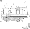
- FIG. 4 A known from the prior art generic pipe connection assembly 1 of a high pressure gas line system 2 of a gas turbine (not shown) comprising double fuel machine 3 is in the FIG. 4 shown.
- this pipe connection arrangement 1 has a pipe element 4 with a connection end 5, which comprises an outer sealing cone 6 and a conical projection 7.
- the pipe connection arrangement 1 has a further pipe element 8 in the form of a nozzle element 9 of the double fuel machine 3, which end comprises an inner sealing cone 10 and an external thread 11.
- the tubular element 4 and the further tubular element 8 are inserted into one another along a central longitudinal axis 12 of the pipe connection arrangement 1, so that the outer sealing cone 6 of the tubular element 4 rests against the inner sealing cone 10 in a form-fitting manner.
- an inner tube part 13 is inserted, wherein the inner tube part 13 is spaced from the first tube member 4 at a distance 14, so that there is a gap 15.
- a sealing element 16 is introduced.
- the two pipe elements 4 and 8 of the pipe joint assembly 1 are clamped together by means of a nut member 17 in the form of a union nut 18 in the direction of the central longitudinal axis 12.
- the union nut 18 is pushed onto the first tubular element 4 and screwed with its internal thread 19 on the external thread 11 of the further tubular element 8.
- an inner clamping cone 20 of the union nut 18 comes into operative contact with the conical projection 7 of the first tube element 4.
- the further the union nut 18 is screwed onto the further tubular element 8 the further the first tubular element 4 is dragged by the inner clamping cone 20 of the union nut 18 in the direction of the further tubular element 8 until finally the outer sealing cone 6 of the first tubular element 4 with the inner sealing cone 8 of the other Tube element 8 are clamped together with the desired biasing force.
- the pipe connection assembly 1 is also fixed with a bulkhead fitting 21 to a Brennermikflansch 22, wherein the further tubular element 8 is performed by an existing in the Brennerthereflansch 22 bore 23.
- the bulkhead screw 21 comprises a nut 24, which is also screwed onto the external thread 11 of the further tubular element 8.
- the further tubular element 8 has a projection 25, against which the burner support flange 22 is clamped by means of the nut 24.
- the in the FIG. 4 shown and known from the prior art pipe connection assembly 1 is thus designed as a cone clamping system 26 with screw (union nut), which can be achieved due to the introduced through the nut 18 in the pipe joint assembly 1 biasing force a good seal.
- the components of such screw as long as fixed and therefore also tightly connected to each other, as long as the cone clamping system 26, in particular its outer sealing cone 6 and inner cone 10, and the cap nut 18 have approximately the same temperature. This is particularly the case when a corresponding system is operated in stationary mode.
- the object of the invention is a pipe connection arrangement which is arranged in a high-pressure fluid conduit system of a dual fuel machine, comprising a first pipe element with an outer sealing cone and a conical approach adjacent thereto, comprising a further pipe element with an inner sealing cone and an external thread, comprising a nut element with an inner clamping cone solved in which the outer sealing cone of the first tubular element is at least partially disposed in the inner sealing cone of the further tubular element and wherein the internal thread of the nut element is screwed onto the external thread of the further tubular element, so that the inner clamping cone of the nut element against the conical approach of the tubular element is drawn such that the outer sealing cone and the inner sealing cone are sealingly clamped together, wherein the threaded sleeve portion of the nut element is configured conical.
- the screw connection to the pipe connection arrangement is made considerably more elastic by the conically configured threaded sleeve region, as a result of which an exceptionally good prestressing on the pipe connection arrangement can be achieved.
- the screw according to the invention differs from the known from the prior art screw, in particular of the in the German utility model DE 91 06 441 described screw connection.
- the conical shape of the present nut element ensures by the spring effect always ensures that the compression of the sealing seat is always maintained when contraction of the cone clamping system.
- the bias generated during assembly thus remains even with different thermal expansion.
- the present screw nut element is characterized on the one hand by the threaded sleeve region and on the other hand by the clamping sleeve region, which are arranged side by side in the longitudinal extent of the pipe connection arrangement, ie in the direction of the central longitudinal axis of the pipe connection arrangement.
- the threaded sleeve region In contrast to the threaded sleeve area, no internal thread but the inner clamping cone is provided on the clamping sleeve area, on which the conical projection of the first tubular element is supported.
- the present nut element is designed as a pull nut, since a tensile mother inherent good elastic properties.
- the object of the invention is also achieved by using a pull nut on a pipe connection assembly of a high pressure fluid conduit system of a dual fuel engine to obtain a sufficient biasing force of a threaded connection of the pipe joint assembly.
- the proposed nut member also offers the advantage of mitigating rapid changes in loads, so-called alternating stresses and load shocks by the now possible elongation.
- the object of the invention is also achieved by a high-pressure fluid conduit system with a pipe connection arrangement, wherein the high-pressure fluid conduit system comprises a pipe connection arrangement according to one of the features described.
- the high-pressure fluid line system is much less susceptible to temperature changes or fluctuations, whereby the risk of unintentional loosening of a screw connection is reduced, especially on double fuel machines.
- the object of the invention is also achieved by a dual fuel machine with a gas turbine connected to a high pressure fluid line system having at least one pipe connection arrangement, the double fuel machine comprising a pipe connection arrangement or a high pressure fluid pipe system according to any of the features described herein.
- the screw nut element can be produced structurally simply with the very good elastic properties if the threaded sleeve region has a conical outer contour.
- Advantageous axial expansion properties of the screw nut element in the direction of the central longitudinal axis of the pipe connection arrangement can be achieved if the threaded sleeve area has a wall cross section which varies in the longitudinal extension of the screw nut element.
- a particularly advantageous embodiment provides that the threaded sleeve region and the external thread of the further tubular element are designed and operatively connected to one another in such a way that the threaded sleeve region and an end region of the further tubular element comprising the external thread are deformable in the same direction.
- the threaded sleeve region has an axial deformation capacity that is more than 20% or more than 40% greater than threaded sleeve regions of nut elements on generic pipe joint assemblies.
- the radial and axial suspension of the screw nut element is in this case increased by the conical design of the screw sleeve element, which is loaded in the threaded sleeve region predominantly by tangential stress.
- With the tapered threaded sleeve portion of the axial deformation can be increased by at least 43%. This would already be a temperature increase or a temperature gradient of about 300 ° K required to reduce the bias of the pipe joint assembly of the invention to zero.
- the axial deformability of the threaded sleeve portion is at least more than twice as high as the axial deformability of the clamping sleeve portion of the nut member.
- the pipe joint assembly can be stably supported particularly in a high pressure fluid pipe system when it is fixed with a bulkhead fitting to a housing member or the like.
- the further tubular element has a threaded shoulder of a bulkhead screw thread, which is arranged axially adjacent to the external thread.
- the same external thread can be used for the nut member and the nut of the bulkhead connection.
- the present pipe connection arrangement can be carried out particularly advantageously if the further pipe element is a premix gas pipe element or an engine-side nozzle element.
- the pipe connection arrangement can do without additional anti-rotation, so it is self-locking.
- the pipe connection arrangement according to the invention provides that not only a thread carries the preload load, but a much more uniform distribution can be achieved at the screw.
- an elastic strain with transition areas so not only the states "solid / loose" can be achieved.
- conventional cone clamping systems can be retained.
- no further safeguards are required.
- a two-dimensional bearing behavior and a more uniform load distribution in the thread can be achieved.
- the pipe joint assembly according to the invention provides a simple construction, a simple production, a simple installation and consequently a very inexpensive solution.
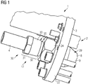
- pipe connection assembly 1 is incorporated in a high pressure fluid conduit system 2 of a dual fuel machine 3.
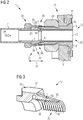
- the pipe connection assembly 1 consists essentially of a first pipe element 4, a further pipe element 8 and a nut member 17, to connect the two pipe elements 4 and 8 by means of a screw 30 fixed and sealing each other.
- the first tube element 4 has an outer sealing cone 6 and a conical projection 7.
- the further tubular element 8 has an inner sealing cone 10 and an external thread 11.
- the nut member 17 is characterized by an inner clamping cone 20 having clamping sleeve portion 31 and by an internal thread 19 having threaded sleeve portion 32.
- the outer sealing cone 6 of the first tubular element 4 is in this case at least partially inserted into the inner sealing cone 10 of the further tubular element 8.
- the internal thread 19 of the nut member 17 is screwed onto the external thread 11 of the further tube member 8, whereby the inner clamping cone 20 of the nut member 17 is pulled against the conical projection 7 of the first tube member 4 such that the outer sealing cone 6 and the inner cone 10 sealingly clamped together are, so that thereby a cone clamping system 26 is provided.
- a circumferential groove 28 is inserted, in which a soft sealing element (not shown here) can be inserted to improve the tightness of the cone clamping system 26.
- the threaded sleeve portion 32 of the nut member 17 is designed according to the invention conical so as to respect previously described cone clamping system 26 to provide a screw 30 with a sufficiently high bias in the pipe joint assembly 1.
- the screw nut member 17 in the context of the invention in particular a pull nut 33, which can always produce a sufficiently high bias on the pipe joint assembly 1 through the specially designed threaded sleeve portion 32, even if the cone clamping system 26 due to cooling by a in the tube elements 4 and 8 initiated transiently cold gas 34 contracts strongly, but the screw nut member 17 in the short term not also cools so strong.
- the threaded sleeve portion 32 of the nut member 17 has a conical outer contour 35, whereby the wall 36 of the nut member 17 at this threaded sleeve portion 32 is very elastic and stretchable.
- the threaded sleeve portion 32 has a longitudinal extent 37 of the nut member 17 variable wall cross-section 38.
- the further tube element 8 is a premix gas tube element 39, which is designed as a nozzle element 9 of the dual fuel machine 3.
- the further tubular element 8 is fixed with a bulkhead screw 21 to a burner support flange 22 of the dual fuel machine 3.
- a further nut 24 is screwed onto the external thread 11, which finally defines the burner support flange 22 against a projection 25 of the further tubular element 8.
Landscapes
- Engineering & Computer Science (AREA)
- General Engineering & Computer Science (AREA)
- Mechanical Engineering (AREA)
- Chemical & Material Sciences (AREA)
- Combustion & Propulsion (AREA)
- Fuel-Injection Apparatus (AREA)
- Joints With Pressure Members (AREA)
- Feeding And Controlling Fuel (AREA)
Claims (8)
- Agencement ( 1 ) de liaison de tuyau pour un système ( 2 ) de conduites de fluide sous haute pression d'une machine ( 3 ) à combustible double, comprenant un premier élément ( 4 ) de tuyau, ayant un cône ( 6 ) d'étanchéité extérieur et un épaulement ( 7 ), qui en est voisin,
comprenant un autre élément ( 8 ) de tuyau, ayant un cône ( 10 ) d'étanchéité intérieur et un filetage ( 11°), comprenant un élément ( 17 ) d'écrou, ayant une partie ( 31 ) de douille de serrage, comportant un cône ( 20 ) de serrage intérieur, et une partie ( 32 ) de douille filetée, comportant un taraudage ( 19 ), le cône ( 6 ) d'étanchéité extérieur du premier élément ( 4 ) de tuyau étant disposé, au moins en partie, dans le cône ( 10 ) d'étanchéité intérieur de l'autre élément ( 8 ) de tuyau et le taraudage ( 19 ) de l'élément ( 17 ) d'écrou étant vissé sur le filetage ( 11 ) de l'autre élément ( 8 ) de tuyau, de manière à ce que le cône ( 20 ) de serrage intérieur de l'élément ( 17 ) d'écrou soit tiré sur l'épaulement ( 7 ) conique du premier élément ( 4 ) de tuyau, de façon à serrer le cône ( 6 ) d'étanchéité extérieur et le cône ( 10 ) d'étanchéité intérieur, l'un à l'autre, d'une manière étanche,
dans lequel la partie ( 32 ) de douille filetée de l'élément ( 17 ) d'écrou est conique. - Agencement ( 1 ) de liaison de tuyau suivant la revendication 1,
dans lequel la partie ( 32 ) de douille filetée a un contour ( 35 ) extérieur conique. - Agencement ( 1 ) de liaison de tuyau suivant la revendication 1 ou 2,
dans lequel la partie ( 32 ) de douille filetée a une section ( 38 ) transversale de paroi se modifiant dans l'étendue ( 37 ) longitudinale de l'élément ( 17 ) d'écrou. - Agencement ( 1 ) de liaison de tuyau suivant l'une des revendications 1 à 3,
dans lequel la partie ( 32 ) de douille filetée et le filetage ( 11 ) de l'autre élément ( 8 ) de tuyau sont conformés et sont en liaison d'action entre eux, de manière à ce que la partie ( 32 ) de douille filetée et une partie d'extrémité, comprenant le filetage ( 11 ) de l'autre élément ( 8 ) de tuyau, puissent être déformées dans le même sens. - Agencement ( 1 ) de liaison de tuyau suivant l'une des revendications 1 à 4,
dans lequel l'autre élément ( 8 ) de tuyau est un élément ( 39 ) de tuyau de gaz de pré-mélange, ou un élément ( 9 ) de conduit du côté du moteur à combustion interne. - Système ( 2 ) de conduites de fluide sous haute pression ayant un agencement ( 1 ) de tuyau,
dans lequel le système ( 2 ) de conduites de fluide sous haute pression comprend un agencement ( 1 ) de tuyau suivant l'une des revendications précédentes. - Machine ( 3 ) à deux combustibles, comprenant une turbine à gaz raccordée à un système ( 2 ) de conduites de fluide sous haute pression, qui a au moins un agencement ( 1 ) de liaison de tuyau,
la machine ( 3 ) à deux combustibles comprenant un agencement ( 1 ) de liaison de tuyau ou un système ( 2 ) de conduites de fluide sous haute pression suivant l'une des revendications précédentes. - Utilisation d'un écrou ( 33 ) de traction sur un agencement ( 1 ) de liaison de tuyau d'un système ( 2 ) de conduites de fluide sous haute pression d'une machine ( 3 ) à deux combustibles, pour obtenir une force de précontrainte suffisante d'un vissage ( 30 ) de l'agencement ( 1 ) de liaison de tuyau, l'écrou ( 33 ) de traction étant conformé sous la forme d'un élément ( 17 ) d'écrou, ayant une partie ( 31 ) de douille de serrage, comportant un cône ( 20 ) de serrage intérieur, et une partie ( 32 ) de douille filetée, comportant un taraudage ( 19 ), la partie ( 32 ) de douille filetée de l'élément ( 17 ) d'écrou étant conique.
Priority Applications (1)
| Application Number | Priority Date | Filing Date | Title |
|---|---|---|---|
| EP14758818.0A EP3017227B1 (fr) | 2013-09-20 | 2014-08-21 | Agencement de liaison de tube, système de conduites de fluide haute pression d'un moteur à combustion interne dualfuel, moteur à combustion interne dualfuel et utilisation d'un écrou de serrage |
Applications Claiming Priority (3)
| Application Number | Priority Date | Filing Date | Title |
|---|---|---|---|
| EP13185330.1A EP2851600A1 (fr) | 2013-09-20 | 2013-09-20 | Agencement de liaison de tube, système de conduites de fluide haute pression d'un moteur à combustion interne dualfuel, moteur à combustion interne dualfuel et utilisation d'un écrou de serrage |
| PCT/EP2014/067831 WO2015039832A1 (fr) | 2013-09-20 | 2014-08-21 | Ensemble de raccordement de tuyaux, système de conduites de fluide haute pression d'un double moteur à combustion interne, double moteur à combustion interne et utilisation d'un écrou de traction |
| EP14758818.0A EP3017227B1 (fr) | 2013-09-20 | 2014-08-21 | Agencement de liaison de tube, système de conduites de fluide haute pression d'un moteur à combustion interne dualfuel, moteur à combustion interne dualfuel et utilisation d'un écrou de serrage |
Publications (2)
| Publication Number | Publication Date |
|---|---|
| EP3017227A1 EP3017227A1 (fr) | 2016-05-11 |
| EP3017227B1 true EP3017227B1 (fr) | 2017-06-14 |
Family
ID=49230583
Family Applications (2)
| Application Number | Title | Priority Date | Filing Date |
|---|---|---|---|
| EP13185330.1A Withdrawn EP2851600A1 (fr) | 2013-09-20 | 2013-09-20 | Agencement de liaison de tube, système de conduites de fluide haute pression d'un moteur à combustion interne dualfuel, moteur à combustion interne dualfuel et utilisation d'un écrou de serrage |
| EP14758818.0A Active EP3017227B1 (fr) | 2013-09-20 | 2014-08-21 | Agencement de liaison de tube, système de conduites de fluide haute pression d'un moteur à combustion interne dualfuel, moteur à combustion interne dualfuel et utilisation d'un écrou de serrage |
Family Applications Before (1)
| Application Number | Title | Priority Date | Filing Date |
|---|---|---|---|
| EP13185330.1A Withdrawn EP2851600A1 (fr) | 2013-09-20 | 2013-09-20 | Agencement de liaison de tube, système de conduites de fluide haute pression d'un moteur à combustion interne dualfuel, moteur à combustion interne dualfuel et utilisation d'un écrou de serrage |
Country Status (5)
| Country | Link |
|---|---|
| US (1) | US10281068B2 (fr) |
| EP (2) | EP2851600A1 (fr) |
| JP (1) | JP6224230B2 (fr) |
| CN (1) | CN105556188B (fr) |
| WO (1) | WO2015039832A1 (fr) |
Families Citing this family (11)
| Publication number | Priority date | Publication date | Assignee | Title |
|---|---|---|---|---|
| DE102016207703A1 (de) * | 2016-05-04 | 2017-11-09 | Robert Bosch Gmbh | Riementrieb, beispielsweise riemengetriebener Startergenerator |
| CN109058639B (zh) * | 2018-10-17 | 2024-01-26 | 西南交通大学 | 一种真空交通管道的伸缩补偿接口 |
| CN209944710U (zh) * | 2019-05-06 | 2020-01-14 | 广东美的制冷设备有限公司 | 排水结构、空调室内机及空调器 |
| CN112049993B (zh) * | 2020-07-24 | 2025-03-11 | 中国航天空气动力技术研究院 | 能够快速更换的高压气流量测量与控制装置及更换方法 |
| CN113464285A (zh) * | 2021-08-02 | 2021-10-01 | 中国航发贵阳发动机设计研究所 | 内置式双油路燃油总管安装结构 |
| EP4303429B1 (fr) * | 2022-07-08 | 2025-03-26 | Volvo Truck Corporation | Agencement de raccord de tuyaux pour un système de gestion de fluide |
| DE102022207493A1 (de) * | 2022-07-21 | 2024-02-01 | Rolls-Royce Deutschland Ltd & Co Kg | Verbindungsvorrichtung zur Strömungsverbindung zwischen einem Kraftstoff- Zuleitungssystem und einer Düsenvorrichtung, Düsenvorrichtung und Gasturbinenanordnung |
| CN119594430B (zh) * | 2023-09-08 | 2025-11-25 | 中国航发商用航空发动机有限责任公司 | 燃烧室级间段结构、燃烧室、航空发动机 |
| US12339003B2 (en) | 2023-09-18 | 2025-06-24 | GE Marmara Technology Center Muhendislik Hizmetleri Ltd | Gas turbine engine and fuel nozzle therefor |
| US12613035B1 (en) | 2024-09-16 | 2026-04-28 | General Electric Company | Combustion section for a turbine engine |
| US12480657B1 (en) | 2025-04-29 | 2025-11-25 | General Electric Company | Gas turbine engine and fuel nozzle therefor |
Family Cites Families (28)
| Publication number | Priority date | Publication date | Assignee | Title |
|---|---|---|---|---|
| US2033409A (en) * | 1934-08-06 | 1936-03-10 | Cleveland J Wilkinson | Oil well device |
| GB2064006B (en) * | 1979-11-24 | 1983-09-14 | Rolls Royce | Dual fuel system for a gas turbine engine |
| DE3709819A1 (de) * | 1986-05-12 | 1987-11-19 | Waluga Armaturen | Rohrverschraubung |
| DE3743170C1 (en) * | 1987-12-19 | 1989-05-18 | Karl Dipl-Ing Weinhold | Pipe screw-connection |
| CN2041757U (zh) | 1988-12-06 | 1989-07-26 | 沈阳工程机械厂 | 高压管接头 |
| US5060988A (en) * | 1990-05-08 | 1991-10-29 | Nwd International, Inc. | Hydraulic coupling |
| DE9106441U1 (de) * | 1991-05-25 | 1991-08-08 | Karl Hamacher GmbH, 4630 Bochum | Rohrkupplung |
| US5263312A (en) * | 1992-07-21 | 1993-11-23 | General Electric Company | Tube fitting for a gas turbine engine |
| IT1264422B1 (it) * | 1993-05-12 | 1996-09-23 | Agip Spa | Giunto per la connessione rapida a tenuta di tubazioni, particolarmente adatto per tubazioni petrolifere |
| US5350200A (en) * | 1994-01-10 | 1994-09-27 | General Electric Company | Tube coupling assembly |
| US5890746A (en) * | 1996-12-18 | 1999-04-06 | General Electric Company | Cooled and wetted redundant seal tube fitting |
| US5725259A (en) | 1996-12-19 | 1998-03-10 | Dials; Carroll P. | Conduit coupling |
| US6487860B2 (en) * | 2000-12-08 | 2002-12-03 | General Electric Company | Turbine engine fuel supply system |
| US20040094959A1 (en) * | 2002-11-19 | 2004-05-20 | Sami Shemtov | Device for coupling two conduits |
| DE102005026580B3 (de) * | 2005-06-08 | 2006-06-22 | Eifeler Maschinenbau Gmbh | Rohrverbindung mit einem umgeformten Rohr |
| US7484776B2 (en) * | 2005-07-14 | 2009-02-03 | Stinger Wellhead Protection, Inc. | High-pressure threaded union with metal-to-metal seal, and metal ring gasket for same |
| EP2184525B1 (fr) | 2008-11-06 | 2011-10-19 | Eifeler Maschinenbau GmbH | Raccordement de tuyau avec un tuyau et procédé de fabrication d'une section de raccordement d'un raccordement de tuyau |
| JP2010242712A (ja) | 2009-04-09 | 2010-10-28 | Otics Corp | フューエルデリバリパイプ |
| US8555648B2 (en) | 2010-02-12 | 2013-10-15 | General Electric Company | Fuel injector nozzle |
| CN102269303A (zh) * | 2010-06-02 | 2011-12-07 | 北汽福田汽车股份有限公司 | 汽车制动油管 |
| CN103748397B (zh) | 2011-04-01 | 2016-05-04 | 帕克-汉尼芬制造业德国有限责任两合公司 | 用于管路或软管管路的、带有锥形螺纹的耐高压的螺旋连接部 |
| CN202195187U (zh) * | 2011-07-18 | 2012-04-18 | 宁波管通机械有限公司 | 叉车管路连接管 |
| CN202195817U (zh) | 2011-08-25 | 2012-04-18 | 中国科学院西安光学精密机械研究所 | 基于图像判读的双激光束平面定位系统 |
| DE102011111524A1 (de) | 2011-08-31 | 2013-02-28 | Richard Weinhold | Vorrichtung zum Verbinden von Doppelmantelrohren |
| US9163841B2 (en) * | 2011-09-23 | 2015-10-20 | Siemens Aktiengesellschaft | Cast manifold for dry low NOx gas turbine engine |
| CN203115333U (zh) * | 2012-12-30 | 2013-08-07 | 浙江普利司汽车零部件有限公司 | 汽车空调无焊接管路接头 |
| EP2827042A1 (fr) * | 2013-07-15 | 2015-01-21 | Siemens Aktiengesellschaft | Raccord de tuyauterie pour le passage d'un fluide sous pression |
| CA2875512C (fr) * | 2014-12-18 | 2015-12-08 | Westport Power Inc. | Structure d'etancheite pour combustible gazeux |
-
2013
- 2013-09-20 EP EP13185330.1A patent/EP2851600A1/fr not_active Withdrawn
-
2014
- 2014-08-21 JP JP2016515391A patent/JP6224230B2/ja active Active
- 2014-08-21 CN CN201480051784.9A patent/CN105556188B/zh active Active
- 2014-08-21 US US15/021,427 patent/US10281068B2/en active Active
- 2014-08-21 WO PCT/EP2014/067831 patent/WO2015039832A1/fr not_active Ceased
- 2014-08-21 EP EP14758818.0A patent/EP3017227B1/fr active Active
Also Published As
| Publication number | Publication date |
|---|---|
| WO2015039832A1 (fr) | 2015-03-26 |
| JP2016539283A (ja) | 2016-12-15 |
| EP2851600A1 (fr) | 2015-03-25 |
| EP3017227A1 (fr) | 2016-05-11 |
| US20160223106A1 (en) | 2016-08-04 |
| US10281068B2 (en) | 2019-05-07 |
| JP6224230B2 (ja) | 2017-11-01 |
| CN105556188A (zh) | 2016-05-04 |
| CN105556188B (zh) | 2019-08-02 |
Similar Documents
| Publication | Publication Date | Title |
|---|---|---|
| EP2851600A1 (fr) | Agencement de liaison de tube, système de conduites de fluide haute pression d'un moteur à combustion interne dualfuel, moteur à combustion interne dualfuel et utilisation d'un écrou de serrage | |
| EP2534401B1 (fr) | Dispositif de raccordement pour un tuyau en matière plastique | |
| DE19607521C1 (de) | Kraftstoff-Verteilerrohr | |
| EP2905461B1 (fr) | Installation d'injection de carburant dotée d'un composant destiné à guider le carburant, d'une soupape d'injection de carburant et d'un support | |
| EP4115107B1 (fr) | Raccord de tuyauterie | |
| EP2829782A1 (fr) | Selle pour un raccord de dérivation | |
| EP2413012A2 (fr) | Connecteur à fiches | |
| EP2986882B1 (fr) | Raccord de tuyauterie pour le passage d'un fluide sous pression | |
| EP3245433B1 (fr) | Dispositif de liaison pour former une liaison hydraulique | |
| EP0428120A2 (fr) | Pièce de connexion détachable pour conduits | |
| AT501851B1 (de) | Verbindung von leitungen für hochdruckmedien | |
| WO2010040334A1 (fr) | Accouplement à verrouillage | |
| DE102015216150A1 (de) | Dichtungsanordnung für eine Kraftstoffzuleitung | |
| DE112017002558T5 (de) | Kraftstoff-Verteilungsvorrichtung | |
| EP3037709B1 (fr) | Systeme de fixation d'un raccord de tuyau pour système d'air de suralimentation | |
| EP2873899B1 (fr) | Système de couplage destiné à relier deux conduites de fluide | |
| DE102011086005A1 (de) | Kraftstoffinjektor, Verfahren zur Montage eines Kraftstoffinjektors sowie Spanneinrichtung zur Montage eines Kraftstoffinjektors | |
| DE102012012422B4 (de) | Befestigungsanordnung einer Kraftstoffleitung an einem Injektor | |
| EP1780403B1 (fr) | Soupape d'injection de combustible | |
| DE102007012536B4 (de) | Leitung mit Knickschutzhülse und Knickschutzhülse | |
| DE10309311A1 (de) | Kraftstoffhockdruckspeicher | |
| DE2943745C2 (fr) | ||
| DE102004054754B4 (de) | Lösbare Hochdruckverbindung zwischen einem Druckspeicher und/oder Druckverteiler und einer Druckleitung | |
| EP3772602B1 (fr) | Unité de piston de cylindre de traction | |
| DE102011052907A1 (de) | Hochdruckfeste Anschlussverbindung, insbesondere in Kraftstoff-Einspritzsystemen |
Legal Events
| Date | Code | Title | Description |
|---|---|---|---|
| PUAI | Public reference made under article 153(3) epc to a published international application that has entered the european phase |
Free format text: ORIGINAL CODE: 0009012 |
|
| 17P | Request for examination filed |
Effective date: 20160201 |
|
| AK | Designated contracting states |
Kind code of ref document: A1 Designated state(s): AL AT BE BG CH CY CZ DE DK EE ES FI FR GB GR HR HU IE IS IT LI LT LU LV MC MK MT NL NO PL PT RO RS SE SI SK SM TR |
|
| AX | Request for extension of the european patent |
Extension state: BA ME |
|
| RIN1 | Information on inventor provided before grant (corrected) |
Inventor name: DUEMLER, HARTWIG Inventor name: XU, CHANGSHENG Inventor name: HESSE, WERNER Inventor name: STARING, SASCHA Inventor name: ROSENKRANZ, JOSEF Inventor name: BOETTCHER, ANDREAS Inventor name: NUDING, JOACHIM-RENE Inventor name: LAPP, PATRICK |
|
| DAX | Request for extension of the european patent (deleted) | ||
| GRAP | Despatch of communication of intention to grant a patent |
Free format text: ORIGINAL CODE: EPIDOSNIGR1 |
|
| RIC1 | Information provided on ipc code assigned before grant |
Ipc: F16L 19/02 20060101ALI20161216BHEP Ipc: F16L 51/00 20060101ALI20161216BHEP Ipc: F02C 9/40 20060101ALI20161216BHEP Ipc: F16L 19/025 20060101AFI20161216BHEP Ipc: F02C 7/22 20060101ALI20161216BHEP Ipc: F23R 3/36 20060101ALI20161216BHEP Ipc: F23R 3/28 20060101ALI20161216BHEP Ipc: F23K 5/14 20060101ALI20161216BHEP |
|
| INTG | Intention to grant announced |
Effective date: 20170117 |
|
| GRAS | Grant fee paid |
Free format text: ORIGINAL CODE: EPIDOSNIGR3 |
|
| GRAA | (expected) grant |
Free format text: ORIGINAL CODE: 0009210 |
|
| AK | Designated contracting states |
Kind code of ref document: B1 Designated state(s): AL AT BE BG CH CY CZ DE DK EE ES FI FR GB GR HR HU IE IS IT LI LT LU LV MC MK MT NL NO PL PT RO RS SE SI SK SM TR |
|
| REG | Reference to a national code |
Ref country code: GB Ref legal event code: FG4D Free format text: NOT ENGLISH |
|
| REG | Reference to a national code |
Ref country code: CH Ref legal event code: EP Ref country code: AT Ref legal event code: REF Ref document number: 901319 Country of ref document: AT Kind code of ref document: T Effective date: 20170615 |
|
| REG | Reference to a national code |
Ref country code: IE Ref legal event code: FG4D Free format text: LANGUAGE OF EP DOCUMENT: GERMAN |
|
| REG | Reference to a national code |
Ref country code: DE Ref legal event code: R096 Ref document number: 502014004258 Country of ref document: DE |
|
| REG | Reference to a national code |
Ref country code: CH Ref legal event code: NV Representative=s name: SIEMENS SCHWEIZ AG, CH |
|
| REG | Reference to a national code |
Ref country code: FR Ref legal event code: PLFP Year of fee payment: 4 |
|
| RAP2 | Party data changed (patent owner data changed or rights of a patent transferred) |
Owner name: SIEMENS AKTIENGESELLSCHAFT |
|
| REG | Reference to a national code |
Ref country code: CH Ref legal event code: PCOW Free format text: NEW ADDRESS: WERNER-VON-SIEMENS-STRASSE 1, 80333 MUENCHEN (DE) |
|
| REG | Reference to a national code |
Ref country code: NL Ref legal event code: MP Effective date: 20170614 |
|
| REG | Reference to a national code |
Ref country code: LT Ref legal event code: MG4D |
|
| PG25 | Lapsed in a contracting state [announced via postgrant information from national office to epo] |
Ref country code: LT Free format text: LAPSE BECAUSE OF FAILURE TO SUBMIT A TRANSLATION OF THE DESCRIPTION OR TO PAY THE FEE WITHIN THE PRESCRIBED TIME-LIMIT Effective date: 20170614 Ref country code: NO Free format text: LAPSE BECAUSE OF FAILURE TO SUBMIT A TRANSLATION OF THE DESCRIPTION OR TO PAY THE FEE WITHIN THE PRESCRIBED TIME-LIMIT Effective date: 20170914 Ref country code: HR Free format text: LAPSE BECAUSE OF FAILURE TO SUBMIT A TRANSLATION OF THE DESCRIPTION OR TO PAY THE FEE WITHIN THE PRESCRIBED TIME-LIMIT Effective date: 20170614 Ref country code: FI Free format text: LAPSE BECAUSE OF FAILURE TO SUBMIT A TRANSLATION OF THE DESCRIPTION OR TO PAY THE FEE WITHIN THE PRESCRIBED TIME-LIMIT Effective date: 20170614 Ref country code: GR Free format text: LAPSE BECAUSE OF FAILURE TO SUBMIT A TRANSLATION OF THE DESCRIPTION OR TO PAY THE FEE WITHIN THE PRESCRIBED TIME-LIMIT Effective date: 20170915 |
|
| PG25 | Lapsed in a contracting state [announced via postgrant information from national office to epo] |
Ref country code: NL Free format text: LAPSE BECAUSE OF FAILURE TO SUBMIT A TRANSLATION OF THE DESCRIPTION OR TO PAY THE FEE WITHIN THE PRESCRIBED TIME-LIMIT Effective date: 20170614 Ref country code: SE Free format text: LAPSE BECAUSE OF FAILURE TO SUBMIT A TRANSLATION OF THE DESCRIPTION OR TO PAY THE FEE WITHIN THE PRESCRIBED TIME-LIMIT Effective date: 20170614 Ref country code: LV Free format text: LAPSE BECAUSE OF FAILURE TO SUBMIT A TRANSLATION OF THE DESCRIPTION OR TO PAY THE FEE WITHIN THE PRESCRIBED TIME-LIMIT Effective date: 20170614 Ref country code: BG Free format text: LAPSE BECAUSE OF FAILURE TO SUBMIT A TRANSLATION OF THE DESCRIPTION OR TO PAY THE FEE WITHIN THE PRESCRIBED TIME-LIMIT Effective date: 20170914 Ref country code: RS Free format text: LAPSE BECAUSE OF FAILURE TO SUBMIT A TRANSLATION OF THE DESCRIPTION OR TO PAY THE FEE WITHIN THE PRESCRIBED TIME-LIMIT Effective date: 20170614 |
|
| PG25 | Lapsed in a contracting state [announced via postgrant information from national office to epo] |
Ref country code: EE Free format text: LAPSE BECAUSE OF FAILURE TO SUBMIT A TRANSLATION OF THE DESCRIPTION OR TO PAY THE FEE WITHIN THE PRESCRIBED TIME-LIMIT Effective date: 20170614 Ref country code: CZ Free format text: LAPSE BECAUSE OF FAILURE TO SUBMIT A TRANSLATION OF THE DESCRIPTION OR TO PAY THE FEE WITHIN THE PRESCRIBED TIME-LIMIT Effective date: 20170614 Ref country code: SK Free format text: LAPSE BECAUSE OF FAILURE TO SUBMIT A TRANSLATION OF THE DESCRIPTION OR TO PAY THE FEE WITHIN THE PRESCRIBED TIME-LIMIT Effective date: 20170614 Ref country code: RO Free format text: LAPSE BECAUSE OF FAILURE TO SUBMIT A TRANSLATION OF THE DESCRIPTION OR TO PAY THE FEE WITHIN THE PRESCRIBED TIME-LIMIT Effective date: 20170614 |
|
| PG25 | Lapsed in a contracting state [announced via postgrant information from national office to epo] |
Ref country code: SM Free format text: LAPSE BECAUSE OF FAILURE TO SUBMIT A TRANSLATION OF THE DESCRIPTION OR TO PAY THE FEE WITHIN THE PRESCRIBED TIME-LIMIT Effective date: 20170614 Ref country code: IS Free format text: LAPSE BECAUSE OF FAILURE TO SUBMIT A TRANSLATION OF THE DESCRIPTION OR TO PAY THE FEE WITHIN THE PRESCRIBED TIME-LIMIT Effective date: 20171014 Ref country code: PL Free format text: LAPSE BECAUSE OF FAILURE TO SUBMIT A TRANSLATION OF THE DESCRIPTION OR TO PAY THE FEE WITHIN THE PRESCRIBED TIME-LIMIT Effective date: 20170614 Ref country code: ES Free format text: LAPSE BECAUSE OF FAILURE TO SUBMIT A TRANSLATION OF THE DESCRIPTION OR TO PAY THE FEE WITHIN THE PRESCRIBED TIME-LIMIT Effective date: 20170614 |
|
| REG | Reference to a national code |
Ref country code: DE Ref legal event code: R097 Ref document number: 502014004258 Country of ref document: DE |
|
| PG25 | Lapsed in a contracting state [announced via postgrant information from national office to epo] |
Ref country code: MC Free format text: LAPSE BECAUSE OF FAILURE TO SUBMIT A TRANSLATION OF THE DESCRIPTION OR TO PAY THE FEE WITHIN THE PRESCRIBED TIME-LIMIT Effective date: 20170614 |
|
| PLBE | No opposition filed within time limit |
Free format text: ORIGINAL CODE: 0009261 |
|
| STAA | Information on the status of an ep patent application or granted ep patent |
Free format text: STATUS: NO OPPOSITION FILED WITHIN TIME LIMIT |
|
| PG25 | Lapsed in a contracting state [announced via postgrant information from national office to epo] |
Ref country code: DK Free format text: LAPSE BECAUSE OF FAILURE TO SUBMIT A TRANSLATION OF THE DESCRIPTION OR TO PAY THE FEE WITHIN THE PRESCRIBED TIME-LIMIT Effective date: 20170614 |
|
| REG | Reference to a national code |
Ref country code: BE Ref legal event code: MM Effective date: 20170831 |
|
| 26N | No opposition filed |
Effective date: 20180315 |
|
| REG | Reference to a national code |
Ref country code: IE Ref legal event code: MM4A |
|
| PG25 | Lapsed in a contracting state [announced via postgrant information from national office to epo] |
Ref country code: LU Free format text: LAPSE BECAUSE OF NON-PAYMENT OF DUE FEES Effective date: 20170821 |
|
| PG25 | Lapsed in a contracting state [announced via postgrant information from national office to epo] |
Ref country code: IE Free format text: LAPSE BECAUSE OF NON-PAYMENT OF DUE FEES Effective date: 20170821 |
|
| REG | Reference to a national code |
Ref country code: FR Ref legal event code: PLFP Year of fee payment: 5 |
|
| PG25 | Lapsed in a contracting state [announced via postgrant information from national office to epo] |
Ref country code: BE Free format text: LAPSE BECAUSE OF NON-PAYMENT OF DUE FEES Effective date: 20170831 Ref country code: SI Free format text: LAPSE BECAUSE OF FAILURE TO SUBMIT A TRANSLATION OF THE DESCRIPTION OR TO PAY THE FEE WITHIN THE PRESCRIBED TIME-LIMIT Effective date: 20170614 |
|
| PG25 | Lapsed in a contracting state [announced via postgrant information from national office to epo] |
Ref country code: MT Free format text: LAPSE BECAUSE OF FAILURE TO SUBMIT A TRANSLATION OF THE DESCRIPTION OR TO PAY THE FEE WITHIN THE PRESCRIBED TIME-LIMIT Effective date: 20170614 |
|
| GBPC | Gb: european patent ceased through non-payment of renewal fee |
Effective date: 20180821 |
|
| PG25 | Lapsed in a contracting state [announced via postgrant information from national office to epo] |
Ref country code: HU Free format text: LAPSE BECAUSE OF FAILURE TO SUBMIT A TRANSLATION OF THE DESCRIPTION OR TO PAY THE FEE WITHIN THE PRESCRIBED TIME-LIMIT; INVALID AB INITIO Effective date: 20140821 |
|
| PG25 | Lapsed in a contracting state [announced via postgrant information from national office to epo] |
Ref country code: GB Free format text: LAPSE BECAUSE OF NON-PAYMENT OF DUE FEES Effective date: 20180821 Ref country code: CY Free format text: LAPSE BECAUSE OF FAILURE TO SUBMIT A TRANSLATION OF THE DESCRIPTION OR TO PAY THE FEE WITHIN THE PRESCRIBED TIME-LIMIT Effective date: 20170614 |
|
| PG25 | Lapsed in a contracting state [announced via postgrant information from national office to epo] |
Ref country code: MK Free format text: LAPSE BECAUSE OF FAILURE TO SUBMIT A TRANSLATION OF THE DESCRIPTION OR TO PAY THE FEE WITHIN THE PRESCRIBED TIME-LIMIT Effective date: 20170614 |
|
| PG25 | Lapsed in a contracting state [announced via postgrant information from national office to epo] |
Ref country code: TR Free format text: LAPSE BECAUSE OF FAILURE TO SUBMIT A TRANSLATION OF THE DESCRIPTION OR TO PAY THE FEE WITHIN THE PRESCRIBED TIME-LIMIT Effective date: 20170614 |
|
| PG25 | Lapsed in a contracting state [announced via postgrant information from national office to epo] |
Ref country code: PT Free format text: LAPSE BECAUSE OF FAILURE TO SUBMIT A TRANSLATION OF THE DESCRIPTION OR TO PAY THE FEE WITHIN THE PRESCRIBED TIME-LIMIT Effective date: 20170614 |
|
| PG25 | Lapsed in a contracting state [announced via postgrant information from national office to epo] |
Ref country code: AL Free format text: LAPSE BECAUSE OF FAILURE TO SUBMIT A TRANSLATION OF THE DESCRIPTION OR TO PAY THE FEE WITHIN THE PRESCRIBED TIME-LIMIT Effective date: 20170614 |
|
| REG | Reference to a national code |
Ref country code: AT Ref legal event code: MM01 Ref document number: 901319 Country of ref document: AT Kind code of ref document: T Effective date: 20190821 |
|
| PG25 | Lapsed in a contracting state [announced via postgrant information from national office to epo] |
Ref country code: AT Free format text: LAPSE BECAUSE OF NON-PAYMENT OF DUE FEES Effective date: 20190821 |
|
| REG | Reference to a national code |
Ref country code: DE Ref legal event code: R081 Ref document number: 502014004258 Country of ref document: DE Owner name: SIEMENS ENERGY GLOBAL GMBH & CO. KG, DE Free format text: FORMER OWNER: SIEMENS AKTIENGESELLSCHAFT, 80333 MUENCHEN, DE |
|
| PGFP | Annual fee paid to national office [announced via postgrant information from national office to epo] |
Ref country code: DE Payment date: 20250827 Year of fee payment: 12 |
|
| PGFP | Annual fee paid to national office [announced via postgrant information from national office to epo] |
Ref country code: IT Payment date: 20250825 Year of fee payment: 12 |
|
| PGFP | Annual fee paid to national office [announced via postgrant information from national office to epo] |
Ref country code: FR Payment date: 20250825 Year of fee payment: 12 |
|
| PGFP | Annual fee paid to national office [announced via postgrant information from national office to epo] |
Ref country code: CH Payment date: 20250901 Year of fee payment: 12 |