EP3017262B1 - Feuerwaffe mit schwenkbarer laufaufnahmeanordnung - Google Patents
Feuerwaffe mit schwenkbarer laufaufnahmeanordnung Download PDFInfo
- Publication number
- EP3017262B1 EP3017262B1 EP14850519.1A EP14850519A EP3017262B1 EP 3017262 B1 EP3017262 B1 EP 3017262B1 EP 14850519 A EP14850519 A EP 14850519A EP 3017262 B1 EP3017262 B1 EP 3017262B1
- Authority
- EP
- European Patent Office
- Prior art keywords
- barrel
- slide plate
- receiver assembly
- bolt
- receiver
- Prior art date
- Legal status (The legal status is an assumption and is not a legal conclusion. Google has not performed a legal analysis and makes no representation as to the accuracy of the status listed.)
- Active
Links
Images


Classifications
-
- F—MECHANICAL ENGINEERING; LIGHTING; HEATING; WEAPONS; BLASTING
- F41—WEAPONS
- F41A—FUNCTIONAL FEATURES OR DETAILS COMMON TO BOTH SMALLARMS AND ORDNANCE, e.g. CANNONS; MOUNTINGS FOR SMALLARMS OR ORDNANCE
- F41A3/00—Breech mechanisms, e.g. locks
- F41A3/58—Breakdown breech mechanisms, e.g. for shotguns
-
- F—MECHANICAL ENGINEERING; LIGHTING; HEATING; WEAPONS; BLASTING
- F41—WEAPONS
- F41A—FUNCTIONAL FEATURES OR DETAILS COMMON TO BOTH SMALLARMS AND ORDNANCE, e.g. CANNONS; MOUNTINGS FOR SMALLARMS OR ORDNANCE
- F41A3/00—Breech mechanisms, e.g. locks
- F41A3/64—Mounting of breech-blocks; Accessories for breech-blocks or breech-block mountings
- F41A3/68—Bolt stops, i.e. means for limiting bolt opening movement
-
- F—MECHANICAL ENGINEERING; LIGHTING; HEATING; WEAPONS; BLASTING
- F41—WEAPONS
- F41A—FUNCTIONAL FEATURES OR DETAILS COMMON TO BOTH SMALLARMS AND ORDNANCE, e.g. CANNONS; MOUNTINGS FOR SMALLARMS OR ORDNANCE
- F41A11/00—Assembly or disassembly features; Modular concepts; Articulated or collapsible guns
-
- F—MECHANICAL ENGINEERING; LIGHTING; HEATING; WEAPONS; BLASTING
- F41—WEAPONS
- F41A—FUNCTIONAL FEATURES OR DETAILS COMMON TO BOTH SMALLARMS AND ORDNANCE, e.g. CANNONS; MOUNTINGS FOR SMALLARMS OR ORDNANCE
- F41A3/00—Breech mechanisms, e.g. locks
- F41A3/64—Mounting of breech-blocks; Accessories for breech-blocks or breech-block mountings
- F41A3/66—Breech housings or frames; Receivers
-
- F—MECHANICAL ENGINEERING; LIGHTING; HEATING; WEAPONS; BLASTING
- F41—WEAPONS
- F41C—SMALLARMS, e.g. PISTOLS, RIFLES; ACCESSORIES THEREFOR
- F41C3/00—Pistols, e.g. revolvers
- F41C3/14—Revolvers
- F41C3/16—Hinge-frame revolvers
-
- F—MECHANICAL ENGINEERING; LIGHTING; HEATING; WEAPONS; BLASTING
- F41—WEAPONS
- F41C—SMALLARMS, e.g. PISTOLS, RIFLES; ACCESSORIES THEREFOR
- F41C7/00—Shoulder-fired smallarms, e.g. rifles, carbines, shotguns
- F41C7/11—Breakdown shotguns or rifles
Definitions
- the present disclosure generally relates to firearms, and more particularly to a pistol with a tilting barrel-receiver assembly as described in US6766795 B .
- Semi-automatic pistols generally include a grip frame having a grip portion for grasping by the user, barrel defining a chamber for holding a cartridge, trigger-actuated firing mechanism for cocking and releasing a striker or hammer to detonate the cartridge, and an axially reciprocating breech block.
- the breach block defines a breech face for forming an openable and closeable breech with the rear of the chamber for firing the pistol and ejecting spent cartridge casings in a manner well known in the art.
- Portions of the frame below the barrel and breech block generally house components of the firing mechanism.
- any reference to direction or orientation is merely intended for convenience of description and is not intended in any way to limit the scope of the present invention.
- Relative terms such as “lower.” “upper,” “horizontal,” “vertical,”, “above,'” “below,” “up,” “down,” “top'' and “bottom” as well as derivative thereof (e.g.. “horizontally,” “downwardly,” “upwardly,” etc.) should be construed to refer to the orientation as then described or as shown in the drawing under discussion. These relative terms are for convenience of description only and do not require that the apparatus be constructed or operated in a particular orientation.
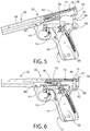
- FIGS. 1 and 2 depict an exemplary embodiment of a semi-automatic firearm in the non-limiting form of a pistol having a pivotable and tilting barrel-receiver assembly according to the present disclosure. It will be appreciated that the present invention is not limited to application in pistols, but may instead be broadly used in other types of firearms including without limitation rifles, shotguns, etc in which a tilting barrel-receiver assembly is desirable.
- Pistol 10 defines a longitudinal axis LA and includes a grip frame 12 having a front trigger guard portion 12a and a barrel-receiver assembly including a barrel 20 and receiver 30.
- the barrel-receiver assembly 20/30 is formed as a single unitary structure with the barrel being integral with the receiver.
- the barrel 20 may be a separate component which is permanently or removably coupled to the front of the receiver 30.
- the rear of the frame 12 defines an elongated grip 16 for holding pistol 10.
- the frame 12 includes an at least partially open interior space 11 for housing the firing mechanism components (see, e.g. FIGS. 5 and 6 ).
- a portion of interior space 11 in grip 16 further defines a magazine well 13 configured to bold a removably intertable magazine (not shown) that contains a plurality of cartridges.
- Frame 12 may be made of any suitable material commonly used in the art including metal, polymer (e g. glass reinforced or unreinforced nylon or other plastic), or combinations thereof;
- Pistol 10 includes a trigger-actuated firing mechanism including a trigger 14 which is operable to cock and release a pivotable hammer 40 (see. e.g. FIGS. 5 and 6 ) in one embodiment.
- a trigger 14 which is operable to cock and release a pivotable hammer 40 (see. e.g. FIGS. 5 and 6 ) in one embodiment.
- Other possible embodiments may instead comprise an axially reciprocating-cockable striker in lieu of a hammer which are well known to those skilled in the art without further elaboration.
- the hammer assembly may further include a hammer strut 41 and spring 42 operable to bias the hammer 40 in a forward direction towards an axially movable firing pin 43.
- Trigger 14 is mechanically linked to hammer 40 and a rotatable sear 44 via trigger bar 45.
- the trigger bar is operable to cock hammer 40 into a rearward ready-to-fire position. Sear 44 operates to hold the hammer in the rearward cocked position. Pulling trigger 14 rotates the sear 44, which in turn releases the hammer 40 to strike the rear end of firing pin 43. The front end of the firing pin strikes a chambered cartridge and discharges the pistol 10.
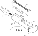
- a spring-biased reciprocating bolt 50 is provided having opposing laterally projecting bolt ears 52 at the rear for manually retracting the bolt (see, e.g. FIGS. 1-2 and 5-12 ).
- Bolt 50 is generally cylindrical in shape as best shown in FIG. 7 and slidably mounted inside receiver 30 for rearward and forward reciprocating movement in recoil upon discharging the pistol.
- the forward face of the bolt 50 defines the breech face.
- bolt 50 is made of steel or an alloy thereof suitable for withstanding the combustion forces generated when detonating a cartridge while maintain a closed breech thereby supporting the rim area of the cartridge.
- Bolt 50 includes a firing pin assembly 54 for striking a chambered cartridge and a cartridge extractor assembly 56 as will be well known in the art (see.
- bolt 50 further includes an axially elongated slot 57 through which a bolt stop pin 80 projects (see FIGS. 6 , 7 , 11 , and 15 ).
- This slot allows the bolt 50 to slide around and past the bolt stop pin 80 both forward/rearward during recoil or when manually opening the breech.
- the rear end of the slot 57 may be arcuately curved and serves as a bolt stop to limit the forward movement and position of the bolt 50 when the breech is closed.
- FIGS. 1-12 show various views of the pistol barrel-receiver assembly 20-30, and related components.
- Barrel 20 includes an open front muzzle end 23 and an open rear end 25.
- Barrel 20 is axially elongated and defines a longitudinally-extending bore 22 extending therethrough that communicates with open ends 23,25. Bore 22 may be rifled.
- the rear portion of barrel 20 defines a chamber 28 configured for holding a cartridge to properly support the cartridge casing when firing the pistol 10.
- the chamber 28 may be configured for holding rimfire type cartridges; however, in certain other embodiments the chamber may be configured for centerfire type cartridges. Both type cartridges are well known to those skilled in the art without further elaboration.
- Receiver 30 may be an axially elongated and generally hollow cylindrical structure defining a longitudinally-extending internal cavity 38.
- Receiver 30 further includes an open front end 31. opposing open rear end 33, and an ejection port 18 (see FIGS. 1-12 ).
- Cavity 38 may be generally circular in cross section and may vary in diameter along the length of the receiver. Cavity 38 may extend axially completely through receiver 30 and communicate with open front and rear ends 31, 33 as shown.
- Open front end 31 of receiver 30 communicates with chamber 28 of the barrel 20 to load cartridges from a magazine (not shown for clarity) disposed in magazine well 13 of the grip frame 12 into the chamber and to extract spent cartridges for ejection through ejection port 18 of the receiver.
- Receiver 30 further includes a bottom cartridge feed opening 38c that communicates with the magazine well for receiving cartridges from the magazine.
- Barrel-receiver assembly 20/30 may be mounted in a pivotable and tilting manner to grip frame 12 via a suitable rotational coupling.
- the barrel-receiver assembly is angularly movable and pivotable between a closed operating (i.e. ready-to-fire) position ( FIG. 1 ) and an open maintenance position ( FIG. 2 ).
- the closed position the barrel-receiver assembly 20/30 and bore 22 of barrel 20 are coaxially aligned with the longitudinal axis LA of pistol 10.
- the barrel-receiver assembly 20/30 and barrel bore 22 are disposed at an angle A1 to the longitudinal axis LA Angle A1 may be between 0 and 90 degrees, and in some embodiments more than 90 degrees.
- the tilting feature provides ready access to the pistol 10 components for inspection and maintenance without requiring the barrel-receiver assembly 10/30 and fasteners (e.g. screws, pins, etc.) to be dismounted from the grip frame 12 and then re-installed.
- fasteners e.g. screws, pins, etc.
- no tools are required to open and close the barrel-receiver assembly 20/30. This allows a user to readily open and inspect the pistol even in the field when ready access to tools (e.g. screwdriver, pin punch, hammer, pliers, etc.) may not be available.
- grip frame 12 includes a lateral pivot pin 60 which engages a transverse mounting hole 61 in barrel-receiver assembly 20/30 to rotationally couple the barrel-receiver assembly to the frame (see, e.g. FIGS. 1 , 2 , 5, and 6 ).
- mounting hole 61 may be disposed proximate to the bottom of the barrel-receiver assembly.
- Pivot pin 60 defines a pivot axis for rotating and tilting barrel-receiver assembly 20/30.
- the pivot pin 60 may be positioned near the front top end of the trigger guard portion 12a of grip frame 12 so that the barrel-receiver assembly 20/30 may be pivoted or tilted without interference from the grip frame.
- pistol 10 further includes a manually-operated latching mechanism 100 which is operable to lock and unlock the barrel-receiver assembly 20/30 to grip frame 12.
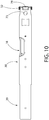
- the latching mechanism may comprise an assembly of a spring-biased slide plate 70, spring 77, elongated spring guide rod 76, and actuator button 78.
- Rod 76 is longitudinally oriented and disposed in receiver 30.
- spring 77 may be a helical compression spring having coils disposed around the rod 76 which act on the front end of and biases a slide plate 70 axially rearwards towards engagement with bolt stop pin 80.
- Other suitable types of spring e g. torsion springs, etc.
- the latching mechanism 100 is configured to selectively engage and disengage the grip frame 12 or an appurtenance thereof to (1) lock the pivoting barrel-receiver assembly 20/30 in the closed position on the grip frame during operation of the pistol (see, e.g. FIG. 1 ), and ( 2 ) to unlock the barrel-receiver assembly so that the assembly may be pivoted to the tilted open position (see, e.g. FIG. 2 ).
- FIGS. 16-22 illustrate different views of a slide plate 70 with an integral actuator button 78.
- Slide plate 70 is substantially horizontally oriented and may be laterally broadened with respect to adjoining portions of rod 76 as shown in one embodiment. Accordingly, slide plate 70 in some configurations may have a lateral width (measured transversely to longitudinal axis LA) which is larger than the diameter of rod 76. In one embodiment, slide plate 70 may have a slightly arcuately curved convex top surface 70a (best shown in FIG. 22 ) when viewed in lateral transverse cross-section to conform to the arcuately curved shape of the top of the tubular receiver 30. Other configurations of the slide plate are suitable and may be used such as a flat top surface for example.
- Slide plate 70 is operated with and moved axially in a horizontal direction via actuator button 78, which may be located rearward of the plate in certain embodiments (see, e.g. FIGS. 1-6 and 8-12 ).
- button 78 may be a unitary structural part of the slide plate disposed at the rear end of the slide plate.
- the actuator button 78 may be a separate component rigidly coupled to the slide plate 70 by any suitable means (e.g. snap fit, shrink fit, welding/soldering, adhesives, fasteners, or other) so that sliding the button forward or rearward moves the slide plate 70 in unison therewith.
- the button 78 may remain separate in construct from slide plate 70 and be slideably arranged in the receiver to engage the rear end of the slide plate.
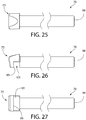
- FIGS. 23-27 illustrate different views of the spring guide rod 76.
- spring guide rod 76 includes a forward end 98 and opposing rear end 75 configured and arranged to engage the front end of slide plate 70.
- the rod 76 may be formed as ether an integral unitary structural part of slide plate 70 or alternatively may be a separate component attached to the slide plate.
- rear end 75 of rod 76 in one configuration may detachably engage the front end of slide plate 70 via a generally snug, but non-permanent connection as shown in FIGS. 3-4 and 14.
- slide plate 70 may include a cross-bar 97 (see, e.g. FIGS.
- the rear end 75 of rod 76 may include a hook 99 configured to engage cross-bar 97.
- a downwardly open slot 101 is formed adjacent and forward of the hook which receives the cross-bar 97 at least partially therein when the hook 99 latches over the cross-bar.
- the spring 77 which engages the front end of the slide plate 70 keeps the hook 99 engaged with the cross-bar 97.
- the slide plate 70 may be affixed to the rear end 75 of the rod via other suitable mechanical attachment means including without limitation a snap fit, shrink fit, welding/soldering, adhesives, fasteners, or other suitable method.
- the slide plate 70 with integral actuator button 78 assembly may be slidably supported by receiver 30 in a rearwardly open elongated channel 79 for rearward and forward axial movement when manually and selectively operated by a user.
- the actuator button 78 is biased in a rearward axial direction by the slide plate 70 which is urged in the same rearward direction by spring 77, as described herein.
- the slide plate 70 is axially movable via the actuator button 78 between a forward unlocked axial position of the slide plate disengaged from the grip frame 12 (see, e.g. FIG. 3 ) and a rearward locked axial position (see. e.g. FIG. 4 ) engaged with the grip frame.
- slide plate 70 may disposed proximate to the rear end 33 of receiver 30 opposite the pivot axis of the barrel-receiver assembly 20/30 at the distal front end 31 of the receiver.
- slide plate 70 is configured and operable to lockingly engage a forward facing locking slot 81 formed in the grip frame 12.
- Slot 81 may be formed in a protrusion on grip frame 12 such as without limitation a vertically oriented latch pin mounted to the frame.
- the bolt stop pin 80 may also serve e as the latch pin thereby combining the dual functions of a latch pin for latching the barrel-receiver assembly 20/30 in the closed position and also as a bolt travel stop for limiting the forward movement and position of the bolt 50 with respect to the barrel 20 and receiver 30.
- the locking slot 81 may be horizontally oriented to engage the horizontally oriented slide plate 70.
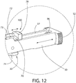
- bolt stop pin 80 may have a cylindrical body in one embodiment
- Bolt stop pin 80 may be metal and affixed to the grip frame 12 of the pistol 10 by any suitable means.
- bolt stop pin 80 may be fixed to grip frame 12 via a lateral mounting pin 82 inserted through opposing holes 84 formed in the sides of the frame (see FIG. 4 ).
- the bolt stop pin 80 includes a pin hole 83 for inserting the mounting pin 82 therethrough. Hole 83 may be formed at any suitable location in the bolt stop pin, such as without limitation proximate to the bottom end of the bolt stop pin as shown.
- the frame 12 is configured to engage the bolt stop pin 80 to prevent the pin from rotating about mounting pin 82. thereby keeping the pin 80 in a stationary position with respect to the frame.
- the bolt stop pin 80 may be affixed to the grip frame 12 in a rigid manner which essentially forms a stiff upright post for securely anchoring the barrel-receiver assembly 20/30 in the closed locked position to the frame.
- This rigid attachment of the bolt stop pin 80 is also advantageous because the bolt stop pin may serve the dual function of both a barrel-receiver assembly 20/30 latch pin and a bolt travel stop which abuttingly engages and arrests the forward return movement of the bolt 50 under recoil after firing the pistol.
- the mutual engagement between the slide plate 70 and slotted bolt stop pin 80 prevents the barrel-receiver assembly 20/30 from being tilted upwards about the pivot axis near the front trigger guard portion 12a of the grip frame when operating the pistol in firing mode.
- the locking slot 81 may be formed proximate to the top end of the bolt stop pin 80 to engage the slide plate 70 disposed in the upper portion of the receiver above the longitudinal cavity 38.
- the top end of the bolt stop pin 80 may be convexly rounded to facilitate reinsertion back through the locking aperture 72 of the slide plate 70 when closing the barrel-receiver assembly 20/30.
- the locking aperture 72 in slide plate 70 in one configuration is configured and arranged to engage a portion of slide plate 70 that is immediately forward of the aperture with the slot 81 in bolt stop pin 80.
- the locking aperture 72 may be formed as a circular hole in one embodiment which extends vertically completely through slide plate 70 between its top and bottom surfaces. Accordingly, aperture 72 lies substantially in the horizontal plane.
- the bolt stop pin 80 is insertable vertically through aperture 72 of slide plate 70. When in the locked position as shown in FIGS. 4 and 6 , a top end portion of bolt stop pin 80 may protrude upwards beyond the top surface of the slid plate 70 and in some embodiments beyond the top surface of the receiver 30.
- receiver 30 may include a pair of vertically spaced apart holes 73 and 74 best shown in FIG.
- the locking portion of the slide plate 70 may be disposed forward of the actuator button 78 portion.
- the locking aperture 72 includes a pair of laterally spaced apart protruding locking ledges 91 which are configured and arranged to engage locking slot 81 of bolt stop pin 80 (see also FIG. 15 ).
- the ledges 91 project laterally inwards and rearward into locking aperture 72.
- Ledges 91 have a height H1 less than the height H2 of the slide plate 70 as best shown in FIG. 17 .
- the ledges 91 have an arcuate shape and are spaced apart less than the diameter of the bolt stop pin 80 to engage the locking slot 81.
- an open channel 92 is formed in slide plate 70 which is in communication with the forward portion of the locking aperture 72 to allow a part of the bolt stop pin 80 to enter the rear of the channel when the locking ledges 91 engage the locking slot 81.
- the channel 92 may be defined by opposing parallel straight sides 93 of the slide plate 70.
- a single continuous arcuately shaped locking ledge 91 may be provided (represented in FIG. 16 by dashed lines) which is arranged to engage locking slot 81 of bolt stop pin 80.
- a ledge may be formed by simply joining the pair of ledges 91 with a central bridge piece having the same curvature to form a continuous arc in configuration.
- the channel 92 may optionally be omitted altogether in such an embodiment.
- slide plate 70 may be provided to selectively engage and disengage the locking slot 81 of bolt stop pin 80.
- latching mechanism may have other various configurations and is expressly not limited by the exemplary embodiments shown and described herein.
- slide plate 70 with actuator button 78 may include a tab 94 which is configured and arranged to engage a pocket 96 formed in the bolt 50.
- This arrangement helps maintain positive engagement between rear end of the slide plate 70 with the bolt 50 (when the bolt is locked during firing to form a closed breech) to prevent the rear end of the slide plate from popping up under the biasing action of the spring 77 on the slide plate and initial recoil forces.
- the tab 94 projects rearward from and is an integral part of an L-shaped protrusion 95 projecting downwards from actuator button 78 behind the locking aperture 72.
- the pocket 96 is formed in the rear end of the bolt intermediate to the pair of bolt ears 52 behind slot 57.
- the bolt 50 travels rearward under recoil and the tab 94 leaves the pocket 96 as the breech is opened.
- the receiver interacts with the slide plate 70 to keep it in position during this time.
- the tab 94 re-enters the pocket 96 and the breech is closed.
- spring guide rod 76. slide plate 70, and bolt stop pin 80 may be made of a suitable metal and/or combination of metals such as without limitation steel including stainless steel, titanium, and or aluminum, In other possible embodiments, some or all of these components or portions thereof may be made of non-metallic materials such as without limitation unfilled or glass reinforced polymers.
- barrel 20 may be made of a metal with suitable toughness and durability to withstand the combustion pressures and temperatures generated when firing the pistol.
- barrel 20 may be made of a suitable steel and alloys thereof.
- the receiver 30 is integral with the barrel 20 and formed of the same material.
- the barrel 20 and receiver 30 are formed as separate components which are mechanically joined together (e.g. threaded or interlocked connections, etc.)
- the receiver 30 may be made of a different material than the barrel such as relatively lighter-weight metal including aluminum, titanium, and alloys thereof to reduce the overall weight of the pistol 10.
- receiver 30 may be made of 6061-T6 aluminum.
- barrel-receiver assembly 20/30 is shown in a downward closed and ready-to-fire operating position.
- Sliding plate 70 is in the rearward locked position engaged with locking slot 81 of bolt stop pin 80.
- the slide plate actuator button 78 is first manually moved axially forward toward the muzzle end 23 of barrel 20.
- the actuator button 78 which acts on a rear end of the slide plate 70, pushes the slide plate in turn forward to the unlocked position.
- the slide plate 70 becomes disengaged from locking slot 81 of bolt stop pin 80 and frees the barrel-receiver assembly 20/30 to be moved pivotally with respect to the grip frame 12 of pistol 10 about pivot pin 60.
- the barrel-receiver assembly 20/30 is pivoted upwards and forward (counter-clockwise as shown in FIGS. 2 , 3 , and 5 ) about pivot pin 60.
- the rear end of the receiver 30 is displaced and vertically moved apart from the rear end of the grip frame 12.
- Barrel-receiver assembly is now in the upward angled open position.
- Barrel-receiver assembly 20 30 is tilted and angled with respect to the longitudinal axis of the pistol 10 in which bolt stop piu 80 is now disengaged completely from barrel-receiver assembly 23/30.
- the barrel-receiver assembly and portions of the grip frame 12 containing the firing mechanism and hammer assembly are now fully accessible to a user for inspection and maintenance.
- the barrel-receiver assembly is pivoted downwards and rearward (clockwise as shown in FIGS. 1 , 5. and 6 ) about pivot pin 60.
- the underside of slide plate 70 first engages the top of the bolt stop pin 80, which in one non-limiting embodiment may be rounded as shown. This automatically slides the slide plate 70 forward slightly against the biasing force of spring 77 so that the top portion of the bolt stop pin 80 may enter aperture 72 in the slide plate.
- the spring-biased slide plate will be free to move rearward and snap into the locking slot.
- the bottom rear end of the receiver 30 abuttingly contacts and becomes fully seated on the top rear end of grip frame 12. Barrel-receiver assembly 20/30 is now returned to its closed and ready-to-fire operating position.
Landscapes
- Engineering & Computer Science (AREA)
- General Engineering & Computer Science (AREA)
- Portable Nailing Machines And Staplers (AREA)
- Storing, Repeated Paying-Out, And Re-Storing Of Elongated Articles (AREA)
- Wing Frames And Configurations (AREA)
Claims (7)
- Schusswaffe mit kippbarer Lauf-Systemkasten-Anordnung, wobei die Schusswaffe Folgendes umfasst:eine Längsachse (LA);einen Rahmen (12);eine Lauf-Systemkasten-Anordnung (20/30), die schwenkbar von dem Rahmen (12) gestützt wird, wobei die Lauf-Systemkasten-Anordnung (20/30) zwischen einer gekippten offenen Position und einer geschlossenen Position winkelig beweglich ist; undeinen Sperrmechanismus (100), der in der Lauf-Systemkasten-Anordnung (20/30) angeordnet ist, wobei der Sperrmechanismus (100) eine Gleitplatte (70) umfasst, die dafür konfiguriert und ausgelegt ist, den Rahmen (12) optional einzurücken oder auszurücken;die Gleitplatte (70), die gleitfähig zwischen einer verriegelten Position, in der die Lauf-Systemkasten-Anordnung (20/30) in der geschlossenen Position gehalten wird, und einer entriegelten Position, in der die Lauf-Systemkasten-Anordnung (20/30) in die offene Position beweglich ist, beweglich ist; undeinen vertikal ausgerichteten Sperrstift, der an dem Rahmen (12) angebracht ist und durch die Gleitplatte (70) eingerückt oder ausgerückt wird;wobei der Sperrstift einen Verriegelungsschlitz (81) umfasst, der durch die Gleitplatte (70) eingerückt oder ausgerückt wird;wobei der Sperrstift ferner dafür konfiguriert und angeordnet ist, mit einem sich hin- und herbewegenden Bolzen (50) einzurücken, der verschiebbar in der Lauf-Systemkasten-Anordnung (20/30) angeordnet ist, wobei der Sperrstift einen Bolzenstoppstift definiert, der die Vorwärtsbewegung des Bolzens (50) stoppen kann.
- Schusswaffe nach Anspruch 1, wobei:die Gleitplatte (70) eine Verriegelungsöffnung (72) umfasst, die dafür konfiguriert ist, den Sperrstift einzurücken oder auszurücken, oderdie Gleitplatte (70) eine Verriegelungsöffnung (72) umfasst, die dafür konfiguriert ist, den Verriegelungsschlitz (81) des Sperrstiftes einzurücken oder auszurücken, oderdie Gleitplatte (70) eine Verriegelungsöffnung (72) umfasst, die dafür konfiguriert ist, den Verriegelungsschlitz (81) des Sperrstiftes einzurücken oder auszurücken, wobei die Verriegelungsöffnung (72) eine Verriegelungsleiste (91) mit verringerter Höhe definiert, die nach innen in die Öffnung (72) hineinragt, wobei die Verriegelungsleiste (91) mit dem Verriegelungsschlitz (81) des Sperrstiftes in Eingriff gebracht werden kann, um die verriegelte Position zu bilden.
- Schusswaffe nach Anspruch 1, wobei ein hinteres Ende der Lauf-Systemkasten-Anordnung (20/30) nach oben schwenkt und ein vorderes Ende der Lauf-Systemkasten-Anordnung (20/30) nach unten schwenkt, wenn die Lauf-Systemkasten-Anordnung (20/30) von der geschlossenen Position in die offene Position bewegt wird.
- Schusswaffe nach Anspruch 1, wobei die Lauf-Systemkasten-Anordnung (20/30) um eine Schwenkachse schwenkt, die sich vor dem Abzug (14) befindet.
- Schusswaffe nach Anspruch 1, wobei die Gleitplatte (70) durch eine Feder (77) in die verriegelte Position vorgespannt ist, optional, wobei der Sperrmechanismus eine axial längliche Stange (76) umfasst, die entlang der Längsachse orientiert und mit einem vorderen Ende der Gleitplatte (70) verbunden ist, wobei die Gleitplatte (70), die Feder (77) und die Stange (76) in der Lauf-Systemkasten-Anordnung (20/30) montiert und mit dieser beweglich sind.
- Schusswaffe nach Anspruch 1, die ferner einen Betätigungsknopf (78) umfasst, der einstückig mit der Gleitplatte (70) gebildet ist und von einer oberen Oberfläche der Gleitplatte (70) nach oben vorsteht, um die Gleitplatte (70) zwischen der verriegelten und der entriegelten Position zu bewegen.
- Schusswaffe nach Anspruch 1, wobei:die Lauf-Systemkasten-Anordnung (20/30) ferner einen sich axial hin- und herbewegenden Bolzen (50) umfasst, der einen offenen und geschlossenen Verschluss bilden kann; unddie Gleitplatte (70) eine Lasche (94) aufweist, die nach hinten vorsteht, wobei die Lasche (94) dafür ausgelegt ist, alternativ eine nach vorne offene Buchse (96), die in einem hinteren Ende des Bolzens (50) gebildet ist, einzurücken oder auszurücken, wenn die Pistole abgefeuert wird.
Applications Claiming Priority (2)
| Application Number | Priority Date | Filing Date | Title |
|---|---|---|---|
| US201361841819P | 2013-07-01 | 2013-07-01 | |
| PCT/US2014/045096 WO2015050606A2 (en) | 2013-07-01 | 2014-07-01 | Firearm with pivoting barrel-receiver assembly |
Publications (3)
| Publication Number | Publication Date |
|---|---|
| EP3017262A2 EP3017262A2 (de) | 2016-05-11 |
| EP3017262A4 EP3017262A4 (de) | 2017-06-21 |
| EP3017262B1 true EP3017262B1 (de) | 2018-08-22 |
Family
ID=52779261
Family Applications (1)
| Application Number | Title | Priority Date | Filing Date |
|---|---|---|---|
| EP14850519.1A Active EP3017262B1 (de) | 2013-07-01 | 2014-07-01 | Feuerwaffe mit schwenkbarer laufaufnahmeanordnung |
Country Status (4)
| Country | Link |
|---|---|
| US (1) | US9291411B2 (de) |
| EP (1) | EP3017262B1 (de) |
| BR (1) | BR112015032762A2 (de) |
| WO (1) | WO2015050606A2 (de) |
Families Citing this family (12)
| Publication number | Priority date | Publication date | Assignee | Title |
|---|---|---|---|---|
| WO2015088794A1 (en) | 2013-12-09 | 2015-06-18 | Osborne William S | Collapsible pistol |
| EP3280968B1 (de) * | 2015-04-09 | 2020-02-26 | Sturm, Ruger & Company, Inc. | Feuerwaffe mit schwenkbarer laufaufnahmeanordnung |
| WO2017077399A2 (en) * | 2015-07-22 | 2017-05-11 | Sagi Faifer | Receiver cover and accessory rail |
| US10215513B2 (en) * | 2015-12-18 | 2019-02-26 | Jeffrey Scott Cross | AR style receiver compatible with pistol magazines and cartridges |
| WO2017136838A1 (en) * | 2016-02-04 | 2017-08-10 | Michael Full | Folding compact pistol |
| US10371475B2 (en) * | 2016-09-21 | 2019-08-06 | Browning | Firearm magazine |
| KR101901224B1 (ko) * | 2016-11-01 | 2018-10-10 | 신원엠에스(주) | 소총 |
| EP3367040B1 (de) * | 2017-02-27 | 2019-10-30 | Glock Technology GmbH | Pistole |
| US10514218B2 (en) * | 2018-05-25 | 2019-12-24 | 03312004 Llc | Firearm and method of forming channels to contain compressible material |
| US11041687B2 (en) | 2018-12-10 | 2021-06-22 | Maxim Defense Industries, LLC | Gas block and barrel assembly and method of fabricating same |
| US11156421B2 (en) * | 2018-12-14 | 2021-10-26 | DK Precision Outdoor, LLC | Firearm and methods for operation and manufacture thereof |
| US12313375B2 (en) * | 2022-09-16 | 2025-05-27 | Zenk Llc | Open frame revolver with changeable drum |
Family Cites Families (51)
| Publication number | Priority date | Publication date | Assignee | Title |
|---|---|---|---|---|
| US970307A (en) * | 1909-07-20 | 1910-09-13 | Smith & Wesson Inc | Automatic pistol. |
| GB156518A (en) | 1917-11-19 | 1921-11-03 | Waldo Emerson Rosebush | Improvements in automatic hand firearms |
| US1363262A (en) | 1918-06-14 | 1920-12-28 | Vickers Ltd | Rifle and machine-gun |
| US2354025A (en) | 1942-07-20 | 1944-07-18 | Kilgore Mfg Co | Firearm |
| US2372614A (en) | 1943-03-05 | 1945-03-27 | Carl G Swebilius | Box-magazine construction for repeating firearms |
| US2585275A (en) * | 1949-08-10 | 1952-02-12 | Sturm Ruger & Co | Receiver and grip connection for autoloading pistols |
| US2809457A (en) * | 1954-06-03 | 1957-10-15 | Clarence E Simpson | Barrel mounting on a pivoted receiver |
| US3153874A (en) * | 1962-08-01 | 1964-10-27 | Merrill Rex Raymond | Hinged barrel firearm with trigger safety means |
| US3318192A (en) * | 1965-02-12 | 1967-05-09 | Armalite Inc | Locked action rifle for automatic and semi-automatic selective firing |
| US3380183A (en) | 1965-02-12 | 1968-04-30 | Armalite Inc | Upper handguard fixedly mounted on barrel assembly by breechblock guide rods |
| ES379338A1 (es) | 1969-04-29 | 1973-04-16 | Beretta Armi Spa | Perfeccionamientos en los fusiles automaticos. |
| US4407085A (en) | 1981-10-02 | 1983-10-04 | Hillberg Robert L | Handgun firing mechanism |
| SE430435B (sv) | 1981-12-14 | 1983-11-14 | Flodman Guns Kb | Ledanordning for ett brytgever |
| EP0210736A1 (de) * | 1985-06-14 | 1987-02-04 | Aserma Manufacturing A Division Of O.M.C. Aserma (Proprietary) Limited | Feuerwaffe |
| FR2585818B1 (fr) | 1985-08-05 | 1987-10-09 | Richert Pierre | Lanceur double gros calibre a canons basculants |
| US4999939A (en) * | 1987-12-31 | 1991-03-19 | Springfield Armory, Inc. | Breech load pistol and conversion |
| US4964232A (en) | 1989-08-30 | 1990-10-23 | U. S. Competition Arms, Inc. | Single barrel break-action trap shotgun |
| US5225619A (en) | 1990-11-09 | 1993-07-06 | Rodgers Instrument Corporation | Method and apparatus for randomly reading waveform segments from a memory |
| US5349773A (en) * | 1992-08-11 | 1994-09-27 | U.S. Competiton Arms, Inc. | Double barrel break-action shotgun |
| US5404863A (en) | 1993-01-06 | 1995-04-11 | Poor; Keith A. | Gas-powered, single-shot gun with tip-up barrel for loading |
| US5467549A (en) | 1993-12-30 | 1995-11-21 | Rowlands; Kenneth C. | Firearm automatic safety system |
| ITMI970419A1 (it) | 1997-02-26 | 1998-08-27 | Franchi S P A | Fucile da caccia a canne sovrapposte con dispositivo per la intercambiabilita' di serie del gruppo canne |
| US6655065B1 (en) | 1997-11-01 | 2003-12-02 | Daniel L. Chapman | Barrel catch mechanism |
| IT1309224B1 (it) | 1999-07-05 | 2002-01-16 | Beretta Armi Spa | Dispositivo di chiusura della canna in pistole semiautomatiche edautomatiche |
| US6293040B1 (en) | 1999-08-27 | 2001-09-25 | Defense Procurement Manufacturing Services, Inc. | Interchangeable weapon receiver for alternate ammunition |
| ES2183684B1 (es) | 2000-07-06 | 2004-06-16 | Industrias El Gamo, Sa | Pistola de aire o gas comprimido. |
| US6526683B1 (en) * | 2001-02-16 | 2003-03-04 | N. Eugene Crandall | Mid-grip high-power pistol |
| US6766795B1 (en) * | 2002-01-28 | 2004-07-27 | Pursuit Marketing, Inc. | Paintball gun having a hinged receiver and method for making same |
| DE10235283C1 (de) | 2002-08-02 | 2003-12-18 | Sat Swiss Arms Technology Ag | Kipplaufwaffe |
| US6604311B1 (en) | 2002-10-12 | 2003-08-12 | Thompson Intellectual Properties, Ltd. | Lever-operated breechblock for muzzle-loading firearm |
| US7065913B2 (en) * | 2002-11-12 | 2006-06-27 | Blackpowder Products, Inc. | Muzzle-loading firearm with pivoting block action |
| US6907687B2 (en) | 2002-12-02 | 2005-06-21 | Browning Arms Company | Over-and-under shotgun apparatus and method |
| US6935063B1 (en) | 2004-04-26 | 2005-08-30 | Steve M. Johnson | Triple-barrel shotgun |
| US6952895B1 (en) * | 2004-07-21 | 2005-10-11 | Kimber Ip, Llc | Magazine disconnect safety |
| WO2006056429A1 (de) | 2004-11-24 | 2006-06-01 | Heckler & Koch Gmbh | Mehrschüssige handfeuerwaffe |
| US7353742B1 (en) * | 2005-04-05 | 2008-04-08 | Kimber Ip, Llc | Double action firing pin system |
| US7316092B2 (en) * | 2005-08-05 | 2008-01-08 | Deleeuw David C | Muzzle-loading firearm and easily removable breech plug for use therewith |
| US7360478B2 (en) | 2005-09-30 | 2008-04-22 | Colt Canada Corporation | Projectile launcher convertible for left or right hand operation |
| US7493718B2 (en) * | 2006-07-10 | 2009-02-24 | Steinkamp Maschinenbau Gmbh & Co. Kg | Rifle with shoulder support |
| ITMI20070106A1 (it) | 2007-01-24 | 2008-07-25 | Beretta Armi Spa | Fucile semiautomatico a corto rinculo |
| US7739821B1 (en) | 2007-05-15 | 2010-06-22 | Wayne Eugene Hamme | Folding pistol |
| US7673553B2 (en) | 2007-05-21 | 2010-03-09 | Karl Lippard | Barrel link for a semiautomatic weapon |
| US7908781B2 (en) | 2008-01-10 | 2011-03-22 | Thompson/Center Arms Company, Inc. | Muzzle loading firearm with break-open action |
| US8087344B2 (en) | 2009-08-19 | 2012-01-03 | Double Nickel Holdings, Llc | Recoil operating pistol with nestable barrel and slide |
| CZ304992B6 (cs) | 2009-09-15 | 2015-03-18 | Česká Zbrojovka A.S. | Střelná zbraň s výklopnou hlavní |
| US8132348B1 (en) | 2010-03-26 | 2012-03-13 | Thomas R Post | Muzzle-loaded rifle action breech assembly |
| US8495831B1 (en) | 2010-12-22 | 2013-07-30 | DoubleTap Defense, LLC | Two shot pistol |
| DE102011054723B4 (de) | 2011-05-02 | 2016-02-18 | German Sport Guns Gmbh | Handfeuerwaffe |
| USD681147S1 (en) | 2011-12-07 | 2013-04-30 | Luxus Arms LLC | Firearm |
| US8701326B2 (en) * | 2011-12-08 | 2014-04-22 | Sturm, Ruger & Company, Inc. | Pistol barrel system and method |
| US8950100B2 (en) * | 2011-12-09 | 2015-02-10 | Sturm, Ruger & Company, Inc. | Slide takedown system and method for firearm |
-
2014
- 2014-07-01 US US14/321,323 patent/US9291411B2/en active Active
- 2014-07-01 WO PCT/US2014/045096 patent/WO2015050606A2/en not_active Ceased
- 2014-07-01 EP EP14850519.1A patent/EP3017262B1/de active Active
- 2014-07-01 BR BR112015032762A patent/BR112015032762A2/pt not_active IP Right Cessation
Non-Patent Citations (1)
| Title |
|---|
| None * |
Also Published As
| Publication number | Publication date |
|---|---|
| US9291411B2 (en) | 2016-03-22 |
| EP3017262A4 (de) | 2017-06-21 |
| US20150247688A1 (en) | 2015-09-03 |
| WO2015050606A3 (en) | 2015-06-04 |
| WO2015050606A2 (en) | 2015-04-09 |
| BR112015032762A2 (pt) | 2017-07-25 |
| EP3017262A2 (de) | 2016-05-11 |
Similar Documents
| Publication | Publication Date | Title |
|---|---|---|
| EP3017262B1 (de) | Feuerwaffe mit schwenkbarer laufaufnahmeanordnung | |
| US10175012B2 (en) | Firearm with pivoting barrel-receiver assembly | |
| EP3129739B1 (de) | Abzugssystem für feuerwaffen | |
| EP2661600B1 (de) | Magazinentnahmemechanismus für eine schusswaffe | |
| US9513074B1 (en) | Firearm with interchangeable parts | |
| US20180195822A1 (en) | Bullpup conversion kit for firearm | |
| US8312656B2 (en) | Shotgun having an improved shotshell feeding mechanism | |
| KR102709716B1 (ko) | 자동 장전식 화기용 무기 리시버 및 무기 리시버가 구비된 자동 장전식 화기 | |
| EP2185888B1 (de) | Leichtes schiesssteuergehäuse für einen revolver | |
| US11578939B2 (en) | Safety mechanism for firearms | |
| US7096618B2 (en) | Pistol with magazine disconnect | |
| US7861449B1 (en) | Cylinder latching mechanism for revolver | |
| US20100071245A1 (en) | Firearm having an improved forearm fastening mechanism | |
| US20250341372A1 (en) | Ambidextrous bolt release mechanism for firearm | |
| EP3137839B1 (de) | Ladesystem für eine schusswaffe | |
| EP3948142B1 (de) | Bolzenauslösemechanismus für schusswaffen | |
| US11808542B2 (en) | Extended slide stop | |
| HK1160209A1 (en) | Firing actuator mechanism for toy gun | |
| HK1192308B (zh) | 槍支 |
Legal Events
| Date | Code | Title | Description |
|---|---|---|---|
| PUAI | Public reference made under article 153(3) epc to a published international application that has entered the european phase |
Free format text: ORIGINAL CODE: 0009012 |
|
| 17P | Request for examination filed |
Effective date: 20151222 |
|
| AK | Designated contracting states |
Kind code of ref document: A2 Designated state(s): AL AT BE BG CH CY CZ DE DK EE ES FI FR GB GR HR HU IE IS IT LI LT LU LV MC MK MT NL NO PL PT RO RS SE SI SK SM TR |
|
| AX | Request for extension of the european patent |
Extension state: BA ME |
|
| RIN1 | Information on inventor provided before grant (corrected) |
Inventor name: ZONSHINE, AMIR |
|
| DAX | Request for extension of the european patent (deleted) | ||
| RIC1 | Information provided on ipc code assigned before grant |
Ipc: F41A 11/00 20060101AFI20170116BHEP Ipc: F41A 21/48 20060101ALI20170116BHEP Ipc: F41A 21/00 20060101ALI20170116BHEP Ipc: F41A 11/04 20060101ALI20170116BHEP Ipc: F41A 3/68 20060101ALI20170116BHEP |
|
| A4 | Supplementary search report drawn up and despatched |
Effective date: 20170519 |
|
| RIC1 | Information provided on ipc code assigned before grant |
Ipc: F41A 21/00 20060101ALI20170515BHEP Ipc: F41A 3/68 20060101ALI20170515BHEP Ipc: F41A 11/00 20060101AFI20170515BHEP Ipc: F41A 21/48 20060101ALI20170515BHEP Ipc: F41A 11/04 20060101ALI20170515BHEP |
|
| GRAP | Despatch of communication of intention to grant a patent |
Free format text: ORIGINAL CODE: EPIDOSNIGR1 |
|
| STAA | Information on the status of an ep patent application or granted ep patent |
Free format text: STATUS: GRANT OF PATENT IS INTENDED |
|
| INTG | Intention to grant announced |
Effective date: 20180426 |
|
| GRAS | Grant fee paid |
Free format text: ORIGINAL CODE: EPIDOSNIGR3 |
|
| GRAA | (expected) grant |
Free format text: ORIGINAL CODE: 0009210 |
|
| STAA | Information on the status of an ep patent application or granted ep patent |
Free format text: STATUS: THE PATENT HAS BEEN GRANTED |
|
| AK | Designated contracting states |
Kind code of ref document: B1 Designated state(s): AL AT BE BG CH CY CZ DE DK EE ES FI FR GB GR HR HU IE IS IT LI LT LU LV MC MK MT NL NO PL PT RO RS SE SI SK SM TR |
|
| REG | Reference to a national code |
Ref country code: GB Ref legal event code: FG4D |
|
| REG | Reference to a national code |
Ref country code: CH Ref legal event code: EP |
|
| REG | Reference to a national code |
Ref country code: CH Ref legal event code: NV Representative=s name: SERVOPATENT GMBH, CH |
|
| REG | Reference to a national code |
Ref country code: AT Ref legal event code: REF Ref document number: 1033004 Country of ref document: AT Kind code of ref document: T Effective date: 20180915 |
|
| REG | Reference to a national code |
Ref country code: IE Ref legal event code: FG4D |
|
| REG | Reference to a national code |
Ref country code: DE Ref legal event code: R096 Ref document number: 602014031087 Country of ref document: DE |
|
| REG | Reference to a national code |
Ref country code: NL Ref legal event code: MP Effective date: 20180822 |
|
| REG | Reference to a national code |
Ref country code: LT Ref legal event code: MG4D |
|
| PG25 | Lapsed in a contracting state [announced via postgrant information from national office to epo] |
Ref country code: SE Free format text: LAPSE BECAUSE OF FAILURE TO SUBMIT A TRANSLATION OF THE DESCRIPTION OR TO PAY THE FEE WITHIN THE PRESCRIBED TIME-LIMIT Effective date: 20180822 Ref country code: BG Free format text: LAPSE BECAUSE OF FAILURE TO SUBMIT A TRANSLATION OF THE DESCRIPTION OR TO PAY THE FEE WITHIN THE PRESCRIBED TIME-LIMIT Effective date: 20181122 Ref country code: RS Free format text: LAPSE BECAUSE OF FAILURE TO SUBMIT A TRANSLATION OF THE DESCRIPTION OR TO PAY THE FEE WITHIN THE PRESCRIBED TIME-LIMIT Effective date: 20180822 Ref country code: GR Free format text: LAPSE BECAUSE OF FAILURE TO SUBMIT A TRANSLATION OF THE DESCRIPTION OR TO PAY THE FEE WITHIN THE PRESCRIBED TIME-LIMIT Effective date: 20181123 Ref country code: LT Free format text: LAPSE BECAUSE OF FAILURE TO SUBMIT A TRANSLATION OF THE DESCRIPTION OR TO PAY THE FEE WITHIN THE PRESCRIBED TIME-LIMIT Effective date: 20180822 Ref country code: NL Free format text: LAPSE BECAUSE OF FAILURE TO SUBMIT A TRANSLATION OF THE DESCRIPTION OR TO PAY THE FEE WITHIN THE PRESCRIBED TIME-LIMIT Effective date: 20180822 Ref country code: FI Free format text: LAPSE BECAUSE OF FAILURE TO SUBMIT A TRANSLATION OF THE DESCRIPTION OR TO PAY THE FEE WITHIN THE PRESCRIBED TIME-LIMIT Effective date: 20180822 Ref country code: NO Free format text: LAPSE BECAUSE OF FAILURE TO SUBMIT A TRANSLATION OF THE DESCRIPTION OR TO PAY THE FEE WITHIN THE PRESCRIBED TIME-LIMIT Effective date: 20181122 Ref country code: IS Free format text: LAPSE BECAUSE OF FAILURE TO SUBMIT A TRANSLATION OF THE DESCRIPTION OR TO PAY THE FEE WITHIN THE PRESCRIBED TIME-LIMIT Effective date: 20181222 |
|
| PG25 | Lapsed in a contracting state [announced via postgrant information from national office to epo] |
Ref country code: LV Free format text: LAPSE BECAUSE OF FAILURE TO SUBMIT A TRANSLATION OF THE DESCRIPTION OR TO PAY THE FEE WITHIN THE PRESCRIBED TIME-LIMIT Effective date: 20180822 Ref country code: HR Free format text: LAPSE BECAUSE OF FAILURE TO SUBMIT A TRANSLATION OF THE DESCRIPTION OR TO PAY THE FEE WITHIN THE PRESCRIBED TIME-LIMIT Effective date: 20180822 Ref country code: AL Free format text: LAPSE BECAUSE OF FAILURE TO SUBMIT A TRANSLATION OF THE DESCRIPTION OR TO PAY THE FEE WITHIN THE PRESCRIBED TIME-LIMIT Effective date: 20180822 |
|
| PG25 | Lapsed in a contracting state [announced via postgrant information from national office to epo] |
Ref country code: RO Free format text: LAPSE BECAUSE OF FAILURE TO SUBMIT A TRANSLATION OF THE DESCRIPTION OR TO PAY THE FEE WITHIN THE PRESCRIBED TIME-LIMIT Effective date: 20180822 Ref country code: CZ Free format text: LAPSE BECAUSE OF FAILURE TO SUBMIT A TRANSLATION OF THE DESCRIPTION OR TO PAY THE FEE WITHIN THE PRESCRIBED TIME-LIMIT Effective date: 20180822 Ref country code: EE Free format text: LAPSE BECAUSE OF FAILURE TO SUBMIT A TRANSLATION OF THE DESCRIPTION OR TO PAY THE FEE WITHIN THE PRESCRIBED TIME-LIMIT Effective date: 20180822 Ref country code: ES Free format text: LAPSE BECAUSE OF FAILURE TO SUBMIT A TRANSLATION OF THE DESCRIPTION OR TO PAY THE FEE WITHIN THE PRESCRIBED TIME-LIMIT Effective date: 20180822 Ref country code: PL Free format text: LAPSE BECAUSE OF FAILURE TO SUBMIT A TRANSLATION OF THE DESCRIPTION OR TO PAY THE FEE WITHIN THE PRESCRIBED TIME-LIMIT Effective date: 20180822 |
|
| REG | Reference to a national code |
Ref country code: DE Ref legal event code: R097 Ref document number: 602014031087 Country of ref document: DE |
|
| PG25 | Lapsed in a contracting state [announced via postgrant information from national office to epo] |
Ref country code: SK Free format text: LAPSE BECAUSE OF FAILURE TO SUBMIT A TRANSLATION OF THE DESCRIPTION OR TO PAY THE FEE WITHIN THE PRESCRIBED TIME-LIMIT Effective date: 20180822 Ref country code: DK Free format text: LAPSE BECAUSE OF FAILURE TO SUBMIT A TRANSLATION OF THE DESCRIPTION OR TO PAY THE FEE WITHIN THE PRESCRIBED TIME-LIMIT Effective date: 20180822 Ref country code: SM Free format text: LAPSE BECAUSE OF FAILURE TO SUBMIT A TRANSLATION OF THE DESCRIPTION OR TO PAY THE FEE WITHIN THE PRESCRIBED TIME-LIMIT Effective date: 20180822 |
|
| PLBE | No opposition filed within time limit |
Free format text: ORIGINAL CODE: 0009261 |
|
| STAA | Information on the status of an ep patent application or granted ep patent |
Free format text: STATUS: NO OPPOSITION FILED WITHIN TIME LIMIT |
|
| 26N | No opposition filed |
Effective date: 20190523 |
|
| PG25 | Lapsed in a contracting state [announced via postgrant information from national office to epo] |
Ref country code: SI Free format text: LAPSE BECAUSE OF FAILURE TO SUBMIT A TRANSLATION OF THE DESCRIPTION OR TO PAY THE FEE WITHIN THE PRESCRIBED TIME-LIMIT Effective date: 20180822 |
|
| PG25 | Lapsed in a contracting state [announced via postgrant information from national office to epo] |
Ref country code: MC Free format text: LAPSE BECAUSE OF FAILURE TO SUBMIT A TRANSLATION OF THE DESCRIPTION OR TO PAY THE FEE WITHIN THE PRESCRIBED TIME-LIMIT Effective date: 20180822 |
|
| GBPC | Gb: european patent ceased through non-payment of renewal fee |
Effective date: 20190701 |
|
| PG25 | Lapsed in a contracting state [announced via postgrant information from national office to epo] |
Ref country code: TR Free format text: LAPSE BECAUSE OF FAILURE TO SUBMIT A TRANSLATION OF THE DESCRIPTION OR TO PAY THE FEE WITHIN THE PRESCRIBED TIME-LIMIT Effective date: 20180822 |
|
| PG25 | Lapsed in a contracting state [announced via postgrant information from national office to epo] |
Ref country code: GB Free format text: LAPSE BECAUSE OF NON-PAYMENT OF DUE FEES Effective date: 20190701 |
|
| PG25 | Lapsed in a contracting state [announced via postgrant information from national office to epo] |
Ref country code: LU Free format text: LAPSE BECAUSE OF NON-PAYMENT OF DUE FEES Effective date: 20190701 |
|
| REG | Reference to a national code |
Ref country code: CH Ref legal event code: PCAR Free format text: NEW ADDRESS: WANNERSTRASSE 9/1, 8045 ZUERICH (CH) |
|
| PG25 | Lapsed in a contracting state [announced via postgrant information from national office to epo] |
Ref country code: PT Free format text: LAPSE BECAUSE OF FAILURE TO SUBMIT A TRANSLATION OF THE DESCRIPTION OR TO PAY THE FEE WITHIN THE PRESCRIBED TIME-LIMIT Effective date: 20181222 Ref country code: FR Free format text: LAPSE BECAUSE OF NON-PAYMENT OF DUE FEES Effective date: 20190731 |
|
| PG25 | Lapsed in a contracting state [announced via postgrant information from national office to epo] |
Ref country code: IE Free format text: LAPSE BECAUSE OF NON-PAYMENT OF DUE FEES Effective date: 20190701 |
|
| PG25 | Lapsed in a contracting state [announced via postgrant information from national office to epo] |
Ref country code: CY Free format text: LAPSE BECAUSE OF FAILURE TO SUBMIT A TRANSLATION OF THE DESCRIPTION OR TO PAY THE FEE WITHIN THE PRESCRIBED TIME-LIMIT Effective date: 20180822 |
|
| REG | Reference to a national code |
Ref country code: AT Ref legal event code: UEP Ref document number: 1033004 Country of ref document: AT Kind code of ref document: T Effective date: 20180822 |
|
| PG25 | Lapsed in a contracting state [announced via postgrant information from national office to epo] |
Ref country code: MT Free format text: LAPSE BECAUSE OF FAILURE TO SUBMIT A TRANSLATION OF THE DESCRIPTION OR TO PAY THE FEE WITHIN THE PRESCRIBED TIME-LIMIT Effective date: 20180822 Ref country code: HU Free format text: LAPSE BECAUSE OF FAILURE TO SUBMIT A TRANSLATION OF THE DESCRIPTION OR TO PAY THE FEE WITHIN THE PRESCRIBED TIME-LIMIT; INVALID AB INITIO Effective date: 20140701 |
|
| PG25 | Lapsed in a contracting state [announced via postgrant information from national office to epo] |
Ref country code: MK Free format text: LAPSE BECAUSE OF FAILURE TO SUBMIT A TRANSLATION OF THE DESCRIPTION OR TO PAY THE FEE WITHIN THE PRESCRIBED TIME-LIMIT Effective date: 20180822 |
|
| PGFP | Annual fee paid to national office [announced via postgrant information from national office to epo] |
Ref country code: DE Payment date: 20250728 Year of fee payment: 12 |
|
| PGFP | Annual fee paid to national office [announced via postgrant information from national office to epo] |
Ref country code: IT Payment date: 20250627 Year of fee payment: 12 |
|
| PGFP | Annual fee paid to national office [announced via postgrant information from national office to epo] |
Ref country code: BE Payment date: 20250724 Year of fee payment: 12 |
|
| PGFP | Annual fee paid to national office [announced via postgrant information from national office to epo] |
Ref country code: AT Payment date: 20250718 Year of fee payment: 12 |
|
| PGFP | Annual fee paid to national office [announced via postgrant information from national office to epo] |
Ref country code: CH Payment date: 20250801 Year of fee payment: 12 |