EP3017782A2 - Systeme d'assistance a l'operation - Google Patents
Systeme d'assistance a l'operation Download PDFInfo
- Publication number
- EP3017782A2 EP3017782A2 EP15192669.8A EP15192669A EP3017782A2 EP 3017782 A2 EP3017782 A2 EP 3017782A2 EP 15192669 A EP15192669 A EP 15192669A EP 3017782 A2 EP3017782 A2 EP 3017782A2
- Authority
- EP
- European Patent Office
- Prior art keywords
- unit
- assistance system
- operation assistance
- pivot axis
- robot arm
- Prior art date
- Legal status (The legal status is an assumption and is not a legal conclusion. Google has not performed a legal analysis and makes no representation as to the accuracy of the status listed.)
- Granted
Links
Images



Classifications
-
- A—HUMAN NECESSITIES
- A61—MEDICAL OR VETERINARY SCIENCE; HYGIENE
- A61B—DIAGNOSIS; SURGERY; IDENTIFICATION
- A61B90/00—Instruments, implements or accessories specially adapted for surgery or diagnosis and not covered by any of the groups A61B1/00 - A61B50/00, e.g. for luxation treatment or for protecting wound edges
- A61B90/50—Supports for surgical instruments, e.g. articulated arms
-
- A—HUMAN NECESSITIES
- A61—MEDICAL OR VETERINARY SCIENCE; HYGIENE
- A61B—DIAGNOSIS; SURGERY; IDENTIFICATION
- A61B34/00—Computer-aided surgery; Manipulators or robots specially adapted for use in surgery
- A61B34/30—Surgical robots
-
- B—PERFORMING OPERATIONS; TRANSPORTING
- B25—HAND TOOLS; PORTABLE POWER-DRIVEN TOOLS; MANIPULATORS
- B25J—MANIPULATORS; CHAMBERS PROVIDED WITH MANIPULATION DEVICES
- B25J18/00—Arms
- B25J18/005—Arms having a curved shape
-
- B—PERFORMING OPERATIONS; TRANSPORTING
- B25—HAND TOOLS; PORTABLE POWER-DRIVEN TOOLS; MANIPULATORS
- B25J—MANIPULATORS; CHAMBERS PROVIDED WITH MANIPULATION DEVICES
- B25J19/00—Accessories fitted to manipulators, e.g. for monitoring, for viewing; Safety devices combined with or specially adapted for use in connection with manipulators
- B25J19/0004—Braking devices
-
- B—PERFORMING OPERATIONS; TRANSPORTING
- B25—HAND TOOLS; PORTABLE POWER-DRIVEN TOOLS; MANIPULATORS
- B25J—MANIPULATORS; CHAMBERS PROVIDED WITH MANIPULATION DEVICES
- B25J9/00—Program-controlled manipulators
- B25J9/02—Program-controlled manipulators characterised by movement of the arms, e.g. cartesian coordinate type
- B25J9/04—Program-controlled manipulators characterised by movement of the arms, e.g. cartesian coordinate type by rotating at least one arm, excluding the head movement itself, e.g. cylindrical coordinate type or polar coordinate type
- B25J9/046—Revolute coordinate type
-
- A—HUMAN NECESSITIES
- A61—MEDICAL OR VETERINARY SCIENCE; HYGIENE
- A61B—DIAGNOSIS; SURGERY; IDENTIFICATION
- A61B90/00—Instruments, implements or accessories specially adapted for surgery or diagnosis and not covered by any of the groups A61B1/00 - A61B50/00, e.g. for luxation treatment or for protecting wound edges
- A61B90/50—Supports for surgical instruments, e.g. articulated arms
- A61B2090/5025—Supports for surgical instruments, e.g. articulated arms with a counter-balancing mechanism
-
- A—HUMAN NECESSITIES
- A61—MEDICAL OR VETERINARY SCIENCE; HYGIENE
- A61B—DIAGNOSIS; SURGERY; IDENTIFICATION
- A61B90/00—Instruments, implements or accessories specially adapted for surgery or diagnosis and not covered by any of the groups A61B1/00 - A61B50/00, e.g. for luxation treatment or for protecting wound edges
- A61B90/50—Supports for surgical instruments, e.g. articulated arms
- A61B2090/508—Supports for surgical instruments, e.g. articulated arms with releasable brake mechanisms
-
- A—HUMAN NECESSITIES
- A61—MEDICAL OR VETERINARY SCIENCE; HYGIENE
- A61B—DIAGNOSIS; SURGERY; IDENTIFICATION
- A61B90/00—Instruments, implements or accessories specially adapted for surgery or diagnosis and not covered by any of the groups A61B1/00 - A61B50/00, e.g. for luxation treatment or for protecting wound edges
- A61B90/50—Supports for surgical instruments, e.g. articulated arms
- A61B90/57—Accessory clamps
- A61B2090/571—Accessory clamps for clamping a support arm to a bed or other supports
-
- A—HUMAN NECESSITIES
- A61—MEDICAL OR VETERINARY SCIENCE; HYGIENE
- A61B—DIAGNOSIS; SURGERY; IDENTIFICATION
- A61B34/00—Computer-aided surgery; Manipulators or robots specially adapted for use in surgery
- A61B34/30—Surgical robots
- A61B34/37—Leader-follower robots
Definitions
- the invention relates to an operation assistance system according to the preamble of claim 1.
- Surgery assistance systems particularly for supporting medical procedures or operations, are well known. Such systems are used, for example, to guide auxiliary instruments, e.g. Camera systems, etc. used.
- an operation assistance system for guiding surgical or medical tools or instruments is known, by means of which, for example, a camera unit having an endoscope is guided controlled.
- the surgical assistance system has a controlled robot kinematics by means of which a surgical or medical tool or instrument mounted on its free end can be moved in a controlled manner in three-dimensional space.
- the robot kinematics comprises, for example, at least one support column, at least one first and second robot arm and at least one instrument support receiving the instrument support.
- a plurality of hydraulic drive units are provided, which can be controlled by appropriate supply or discharge of a fluid medium.
- an articulated arm for holding medical instruments is already known, in which at least one drive unit is provided which can position the articulated arm in an active state and is manually reset in a passive state.
- the drive unit is moved by manual force on a held by the articulated arm instrument.
- this articulated arm has no robot kinematics, that is to say that a medical instrument mounted thereon is only conditionally controllable in three-dimensional space.
- such an articulated arm is not suitable for use for minimally invasive operations, in particular for the controlled guidance or tracking of a camera unit by the operator.
- An essential aspect of the operation assistance system is the fact that each drive unit is assigned a controllable magnetic brake unit, via which the robot kinematics can be decoupled from the drive units.
- controllable magnetic brake units fixed the arms of the robot kinematics position and stable position, ie caused by the drive units, unwanted displacement of the robot kinematics from a predetermined desired position is effectively avoided.
- the robot kinematics is unlocked by the drive units and is manually movable in the unlocked state by the surgeon, in particular by the surgeon quickly and easy to use in a practically any operating position brought.
- all controllable magnetic brake units can be activated or deactivated approximately simultaneously by actuation of a single operating element.
- these are de-energized in the deactivated state and energized in the activated, whereby the frictionally engaged or frictional connection between the respective drive unit and the magnetic brake unit is released and thus the drive unit is released.
- the surgeon can thus initiate the activation of the entire robot kinematics by pressing a control element.
- a magnetic brake unit has at least one magnetic brake, which is preferably held against rotation in a housing and has a front-side friction surface.
- the standing with the threaded spindle in operative connection threaded nut is accommodated in a variant in a nut receptacle which is rotatably mounted in the housing via bearing units.
- the nut receiving a front-side friction lining, which can be brought into a frictional connection with the front-side friction surface of the magnetic brake.
- an instrument carrier is arranged on the second robot arm by means of an angled joint piece, the angled joint piece having a latching shaft with a plurality of free-end latching lugs, which is in operative connection with a latching nut arranged on the second robot arm.
- the angled joint piece is preferably mounted manually rotatable about a fourth pivot axis in a sleeve-like latching shaft guidance unit arranged on the second robot arm.
- the sleeve-like latching shaft guide unit has a first guide or receiving channel section for receiving the latching shaft and an adjoining second guide or receiving channel section for secure rotation of the latching nut.
- the latching shaft is preferably acted upon by means of at least one spring element with a restoring force, which acts in the direction of the locking nut.
- the sleeve-like locking shaft guide unit has a control panel with a plurality of switching or operating elements.
- the control contains u.a. the control element for approximately simultaneous actuation of the controllable magnetic brake units.
- FIG. 1 By way of example, an operation assistance system 1 designed according to the invention for medical interventions or operations for guiding medical, in particular surgical tools and instruments is shown.
- a medical tool or instrument is understood to mean, in particular, a camera unit which is mounted on an endoscope and introduced in a minimally invasive operation via a small-sized surgical opening (“trocar”) into an operating space within a patient's body.
- trocar small-sized surgical opening
- the surgical assistance system 1 consists essentially of a base unit 2 and a robot kinematics comprising a support column 3, a first and second robot arm 4, 5 and possibly an instrument carrier 6, wherein the instrument carrier 6, for example, on the second Robot arm 5 is articulated, preferably by means of an angled joint piece 7.
- the instrument carrier 6 is formed for example for direct recording of the medical tool or instrument or for indirect recording by means of an instrument holder.
- the structure of the robot kinematics is shown in the perspective view of the operation assistance system 1 according to FIG. 1 I see it as an example.
- the base unit 2 comprises a carrier plate 2.1, a preferably multi-part base housing 2.2 and at least one fastening element 2.3, by means of which the surgical assistance system 1 or the base unit 2 can be fastened laterally to an operating table, for example.
- the base housing 2.2 at least one control unit and optionally further functional units are arranged (not shown in the figures).
- the support column 3 has a lower and upper end portion 3 ', 3 ".
- the base unit 2 of the operation assistance system 1 is pivotably connected to the lower end portion 3' of the support column 3 of the robot kinematics by means of a first drive unit 8 pivotable about a first pivot axis SA1
- the first pivot axis SA1 in this case runs vertically to the installation plane of the operation assistance system 1 or operation level or level of the operating table.
- the first robot arm 4 has a first and a second end section 4 ', 4 ", wherein the first end section 4' of the first robot arm 4 with the upper end section 3" of the support column 3 opposite the base unit 2 is pivotably pivoted about a second drive unit 9
- the second pivot axis SA2 and the second end portion 4 "of the first robot arm 4 are pivotally connected to a first end portion 5 'of the second robot arm 5 by a third drive unit 10 about a third pivot axis SA3 a second, the first end portion 5 'opposite end portion 5 "on which in the present embodiment, the angled joint piece 7 is rotatably provided about a fourth pivot axis SA4.
- the angled joint piece 7 is designed for rotatable and detachable receiving a connection portion 6' of the instrument support 6 , namely about a fifth pivot axis SA5.
- the opposite free end 6 "of the instrument carrier 6 forms an instrument receptacle.
- the first to third drive units 8 - 10 are preferably independently controllable via at least one control unit in order to effect a rotary or pivoting movement of the robot kinematics about at least the first to third pivot axes SA1 to SA3.
- the second and third pivot axes SA2, SA3 parallel to each other, whereas the first pivot axis SA1 is oriented perpendicular to the second or third pivot axis SA2, SA3.
- the first drive unit 8 is preferably accommodated in the base housing 2.2 and the second drive unit 9 is either arranged laterally on the support column 3 or integrated or received in the support column 3.
- the third drive unit 10 is either arranged laterally on the first robot arm 4 or integrated therein or accommodated therein.
- the support column 3 extends vertically, substantially along the first pivot axis SA1, ie, is approximately rotatable about its own longitudinal axis.
- the first and second robot arm 4, 5 also extend substantially along a straight line, which preferably runs perpendicular to the second or third pivot axis SA2, SA3. In the present embodiment, at least the first robot arm 4 has a slight curvature.
- the second and / or third drive units 9, 10 are formed by a linear drive unit, which is designed to generate a linear drive movement AB oriented along the longitudinal axis of the support column 2 or the first pivot axis SA1 and / or the first robot arm 4.
- SA3 is a pivot joint 11 comprising a crankshaft-like drive element 12 with the respective linear drive unit 9, 10 in operative connection.
- the linear drive unit is designed as a spindle motor unit.
- the respectively formed as a linear drive unit second and / or third drive unit 9, 10 have in the present embodiment, a motor unit, preferably an electric motor unit 13 which is in operative connection with a motor brake unit 14. To the motor unit 13, a gear unit 15 is connected, via which a threaded spindle 16 is set in rotation.
- the threaded spindle 16 is connected via a spindle nut 17 with a controllable magnetic brake unit 18, which has a housing 18.1, which preferably concentrically extends around the threaded spindle 16 and in which the threaded spindle 16 is at least partially received with your linear motor unit 9, 10 opposite free end ,
- the spindle nut 17 is rotatably mounted in the housing 18.1 via bearing units 18.2, by means of a nut receiver 18.3.
- the nut receiver 18.3 is formed sleeve-like and at least partially received in the housing 18.1 and rotatably supported therein by means of the bearing units 18.2.
- the threaded spindle 16 extends through the sleeve-like nut receiver 18.3.
- a friction surface 20 forming a friction lining is provided at the spindle nut 17 opposite free frontal end of the nut receiver 18.3 .
- a friction surface 20 forming a friction lining is provided at the nut receiver 18.3 then along the threaded spindle 16 then also received in the housing 18.1 and rotatably connected to this magnetic brake 19, which is on the frontal friction surface 20 in frictional engagement with the friction lining of the nut receiver 18.3 can be brought.
- the rotational movement generated by the motor unit 13 is converted into a linear movement of the magnetic brake unit 18, which in turn is connected via a connecting rod 21 with the free crank end of the crankshaft-like drive element 12.
- a spring assembly 22 may be provided.
- the spring arrangement 22 establishes an elastic connection between the crankshaft-like drive element 12 and the opposite first end section 4 'of the second robot arm 4.
- the spring assembly 22 is preferably dimensioned such that the surgeon in the unlocked state of the robot kinematics can adjust these substantially neutral in weight or their robot arms 4, 5 can move in space, regardless of the current angular position of the pivot joint eleventh
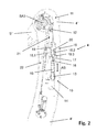
- FIG. 3 3 shows by way of example a perspective sectional representation through the second end section 5 '' of the second robot arm 5 and thus the connection region of the angled joint element 7.
- the angled joint element 7 has at its upper free end 7 'a latching shaft 7.1 and an adjoining latching nut 7.2 7.1 is rotatable about the fourth pivot axis SA4 in the second End portion 5 "of the second robot arm 5 is received, wherein the locking nut 7.2 twist-proof in the second end portion 5" of the second robot arm 5 is arranged.
- a sleeve-like locking shaft guide unit 23 is arranged laterally on the second end portion 5 "of the second robot arm 5, the first guide or receiving channel section 23.1 for receiving the locking shaft 7.1 and an adjoining second guide or
- the diameter of the first guide or receiving channel section 23.1 is smaller than the diameter of the second guide or receiving channel section 23.2, so that in the transition region between said sections 23.1, 23.2 a contact profile for the locking nut element
- the locking nut 7.2 which is received torsionally secure in the second guide or receiving channel section 23.2, has a plurality of detent openings approximately equally distributed about the fourth pivot axis SA4 into which the free-end detent lugs of the detent shaft 7.1 engage, and thus a rotation secure connection between the angled joint member 7 and the latch shaft guide unit 23 on the second robot arm 5 form.
- the locking shaft 7.1 is acted upon by means of a spring element with a restoring force, which acts in the direction of the locking nut 7.2 and thus presses the ELId disorderen detents in the locking openings of the locking nut 7.2.
- a spring element with a restoring force, which acts in the direction of the locking nut 7.2 and thus presses the ELId disorderen detents in the locking openings of the locking nut 7.2.
- Switching or operating elements can be arranged, via which the operator can switch individual or all magnetic brake unit 18 of the linear motor units 9, 10 in such a way that they cause a decoupling of the robot kinematics by the drive units 9, 10 and "unlocked” the robot kinematics by the drive units 9, 10. is.
- the robot kinematics In the "unlocked” state, the robot kinematics can be moved freely manually by the surgeon and can thus be quickly and easily moved to a new desired operating position without requiring a robot kinematics process controlled by the drive units 8 to 10.
- the robot kinematics is locked by means of the magnetic brake units 18 and thus permanently and reliably held in the predetermined position. As a result, the operation of the operation assistance system 1 for the surgeon is much easier.
- the magnetic brake units 18 are de-energized, so that a frictional engagement between the linear motor units 9, 10 and the respectively associated magnetic brake unit 18, 18 * is given.
- the frictional connection or the frictional connection is resolved and disconnected the drive connection.
- the drive units 8 to 10 are unlocked and the robot kinematics can be moved freely in space by the surgeon.
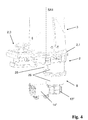
- FIG. 4 shows a perspective view of the base unit 2 of the operation assistance system 1 without the base housing 2.1 in an enlarged detail view.
- FIG. 5 shows a partial section along the first pivot axis SA1 through the first drive unit 8 for driving the support column 2 about the first, vertical pivot axis SA1.
- the first Drive unit 8 has a motor unit, preferably electric motor unit 13 *, which is connected to a transmission unit 14 *.
- the motor unit 13 * is connected via the gear unit 14 * and a magnetic brake unit 18 * to a planetary gear unit 25, wherein the magnetic brake unit 18 * and the planetary gear unit 25 are accommodated in a common outer housing 26.
- the planetary gear unit 25 is itself in turn accommodated in an inner housing 26 *, which is mounted by means of bearing units 27 in the outer housing 26 rotatably about a parallel to the first pivot axis SA1 oriented axis of rotation.
- the magnetic brake unit 18 * in turn has a magnetic brake 19 *, which is rotatably connected to the outer housing 26.
- a friction lining is provided, which has an end-face friction surface 20 * for producing a frictional connection or a frictional connection between the magnetic brake unit 18 * and the planetary gear unit 25.
- an angle sensor unit 28 may be provided for detecting the current rotational angular position of the support column 3 with respect to the first pivot axis SA1.
- At least the robot arms 4, 5 of the robot kinematics are preferably formed as a hollow body or as plate-shaped arm members and made for example of a material which ensures high stability and resilience, to achieve the lowest possible mass has the lowest possible specific gravity and at the same time for imaging or image-forming media, for example for X-rays, magnetic fields or electromagnetic waves is a neutral material.
- a material for the hollow arms formed as a robot arms 4, 5 a fiber-reinforced, for example, carbon fiber reinforced plastic is preferably used.
Landscapes
- Engineering & Computer Science (AREA)
- Health & Medical Sciences (AREA)
- Surgery (AREA)
- Robotics (AREA)
- Life Sciences & Earth Sciences (AREA)
- Mechanical Engineering (AREA)
- Nuclear Medicine, Radiotherapy & Molecular Imaging (AREA)
- Biomedical Technology (AREA)
- Heart & Thoracic Surgery (AREA)
- Medical Informatics (AREA)
- Molecular Biology (AREA)
- Animal Behavior & Ethology (AREA)
- General Health & Medical Sciences (AREA)
- Public Health (AREA)
- Veterinary Medicine (AREA)
- Pathology (AREA)
- Oral & Maxillofacial Surgery (AREA)
- Manipulator (AREA)
- Endoscopes (AREA)
Applications Claiming Priority (1)
| Application Number | Priority Date | Filing Date | Title |
|---|---|---|---|
| DE102014116103.3A DE102014116103A1 (de) | 2014-11-05 | 2014-11-05 | Operations-Assistenz-System |
Publications (3)
| Publication Number | Publication Date |
|---|---|
| EP3017782A2 true EP3017782A2 (fr) | 2016-05-11 |
| EP3017782A3 EP3017782A3 (fr) | 2016-08-17 |
| EP3017782B1 EP3017782B1 (fr) | 2019-10-23 |
Family
ID=54539836
Family Applications (1)
| Application Number | Title | Priority Date | Filing Date |
|---|---|---|---|
| EP15192669.8A Active EP3017782B1 (fr) | 2014-11-05 | 2015-11-03 | Systeme d'assistance a l'operation |
Country Status (5)
| Country | Link |
|---|---|
| US (1) | US20160120606A1 (fr) |
| EP (1) | EP3017782B1 (fr) |
| JP (1) | JP6692147B2 (fr) |
| CN (1) | CN105769342B (fr) |
| DE (1) | DE102014116103A1 (fr) |
Cited By (3)
| Publication number | Priority date | Publication date | Assignee | Title |
|---|---|---|---|---|
| CN106344158A (zh) * | 2016-09-21 | 2017-01-25 | 东莞市联洲知识产权运营管理有限公司 | 一种底部设有升降滚轮的手术机器人 |
| CN106361434A (zh) * | 2016-09-21 | 2017-02-01 | 东莞市联洲知识产权运营管理有限公司 | 一种刀具可多维度运动的手术机器人 |
| WO2018194749A1 (fr) * | 2017-04-21 | 2018-10-25 | Qualcomm Incorporated | Structure mécanique |
Families Citing this family (23)
| Publication number | Priority date | Publication date | Assignee | Title |
|---|---|---|---|---|
| DE102015225183B4 (de) * | 2015-12-15 | 2022-09-15 | Carl Zeiss Meditec Ag | Medizinische Vorrichtung mit einem medizinisch-optischen Gerät und einer Haltevorrichtung und Verfahren zum Betrieb der medizinischen Vorrichtung |
| CN106264733B (zh) * | 2016-09-21 | 2018-12-25 | 青岛市妇女儿童医院 | 一种悬挂式手术器械 |
| CN106175937B (zh) * | 2016-09-21 | 2018-12-21 | 新昌县普达环保科技有限公司 | 一种设有旋转刀具装夹盘的手术机器人 |
| CN106264734B (zh) * | 2016-09-21 | 2018-09-28 | 吴红燕 | 一种设有滚轮底座的手术器械 |
| CN106264735B (zh) * | 2016-09-21 | 2018-09-28 | 吴红燕 | 一种可移动可静置的手术机器人 |
| CN106377318B (zh) * | 2016-11-22 | 2018-09-11 | 哈尔滨工业大学 | 脊柱微创手术机器人实现空间运动串联的三自由度机构 |
| CN106625637A (zh) * | 2016-12-08 | 2017-05-10 | 重庆金创谷医疗科技有限公司 | 机械臂和内镜辅助机械臂装置 |
| DE102017125923A1 (de) | 2017-11-07 | 2019-05-09 | Andreas Karguth | Roboterarm und Roboterarmeinheit |
| CN108742883A (zh) * | 2018-08-31 | 2018-11-06 | 合肥德易电子有限公司 | 用于甲状腺微创手术的机器人 |
| DE102018127857B3 (de) * | 2018-11-08 | 2020-03-19 | Hiwin Technologies Corp. | Roboterarm |
| US10751873B2 (en) | 2018-11-13 | 2020-08-25 | Hiwin Technologies Corp. | Robotic arm |
| US11864857B2 (en) | 2019-09-27 | 2024-01-09 | Globus Medical, Inc. | Surgical robot with passive end effector |
| US11426178B2 (en) | 2019-09-27 | 2022-08-30 | Globus Medical Inc. | Systems and methods for navigating a pin guide driver |
| US12408929B2 (en) | 2019-09-27 | 2025-09-09 | Globus Medical, Inc. | Systems and methods for navigating a pin guide driver |
| US11890066B2 (en) | 2019-09-30 | 2024-02-06 | Globus Medical, Inc | Surgical robot with passive end effector |
| EP4042925B1 (fr) | 2019-12-27 | 2023-10-04 | RIVERFIELD Inc. | Adaptateur de tête de caméra |
| CN111449754A (zh) * | 2020-01-02 | 2020-07-28 | 杭州法博激光科技有限公司 | 适用于输尿管碎石软镜手术的辅助装置 |
| CN111449753A (zh) * | 2020-01-07 | 2020-07-28 | 杭州法博激光科技有限公司 | 输尿管碎石软镜手术机械臂辅助装置 |
| CN114828769B (zh) | 2020-02-18 | 2024-01-09 | 瑞德医疗机器股份有限公司 | 医疗用机器人 |
| DE102020106817A1 (de) | 2020-03-12 | 2021-09-16 | Karl Storz Se & Co. Kg | Andockvorrichtung, chirurgische Haltevorrichtung und Verfahren |
| CN112107367A (zh) * | 2020-04-01 | 2020-12-22 | 杭州法博激光科技有限公司 | 适用于输尿管碎石软镜手术的机械臂辅助装置 |
| CN115533878B (zh) * | 2022-11-02 | 2024-10-08 | 中国科学院深圳先进技术研究院 | 可穿戴于干式潜水服内的水下助力外骨骼肩部关节结构 |
| CN118662080B (zh) * | 2024-08-26 | 2024-10-29 | 青蓝集创医疗设备(成都)有限公司 | 内窥镜镜体角度调整机构、方法、操作柄及内窥镜 |
Citations (2)
| Publication number | Priority date | Publication date | Assignee | Title |
|---|---|---|---|---|
| DE102007019363A1 (de) | 2007-04-23 | 2008-11-06 | Jürgen Michael Knapp | Operations-Assistenz-System |
| DE102011004370A1 (de) | 2011-02-18 | 2012-08-23 | Siemens Aktiengesellschaft | Gelenkarm mit Feststellmechanismus |
Family Cites Families (23)
| Publication number | Priority date | Publication date | Assignee | Title |
|---|---|---|---|---|
| US4250762A (en) * | 1979-03-30 | 1981-02-17 | Warner Electric Brake & Clutch Company | Actuator having a drive screw and a selectively rotatable nut |
| US4506590A (en) * | 1982-07-28 | 1985-03-26 | Shimadzu Coporation | Hydraulic rotary actuator |
| JPS60167785A (ja) * | 1984-02-03 | 1985-08-31 | 新明和工業株式会社 | 産業用ロボツト |
| JPS6189490U (fr) * | 1984-11-14 | 1986-06-11 | ||
| EP0577876B1 (fr) * | 1992-07-09 | 1996-09-04 | TRIENGINEERING Co., Ltd. | Appareil à rouleau pour joindre une pièce |
| US5524180A (en) * | 1992-08-10 | 1996-06-04 | Computer Motion, Inc. | Automated endoscope system for optimal positioning |
| US5762458A (en) * | 1996-02-20 | 1998-06-09 | Computer Motion, Inc. | Method and apparatus for performing minimally invasive cardiac procedures |
| JP2993906B2 (ja) * | 1997-03-31 | 1999-12-27 | 三鷹光器株式会社 | 医療用スタンド装置 |
| US6211591B1 (en) * | 1997-08-27 | 2001-04-03 | Tri-Tech, Inc. | Linear/rotary electromagnetic device |
| FR2782467B1 (fr) * | 1998-08-19 | 2000-09-15 | Commissariat Energie Atomique | Element de liaison a verin a vis et ecrou et son application un bras de robot |
| JP4472361B2 (ja) * | 2004-01-06 | 2010-06-02 | オリンパス株式会社 | 医療器具保持装置及び医療器具保持システム。 |
| WO2007034561A1 (fr) * | 2005-09-26 | 2007-03-29 | Toshiaki Shimada | Robot industriel |
| US9435388B2 (en) * | 2008-04-04 | 2016-09-06 | Freehand 2010 Limited | Clutch mechanism |
| KR20100082225A (ko) * | 2009-01-08 | 2010-07-16 | 삼성전자주식회사 | 로봇용 관절구동장치 및 이를 구비한 로봇 |
| DE102009018917A1 (de) * | 2009-04-28 | 2010-11-18 | Aktormed Gmbh | Operations-Assistenz-System |
| CN101598126B (zh) * | 2009-06-18 | 2010-11-17 | 宁波威克斯液压有限公司 | 子母叶片泵转子加工工艺 |
| GB2472066A (en) * | 2009-07-23 | 2011-01-26 | Medi Maton Ltd | Device for manipulating and tracking a guide tube with radiopaque markers |
| WO2011133873A1 (fr) * | 2010-04-22 | 2011-10-27 | Blue Belt Technologies, Llc | Suiveur d'outil chirurgical piloté reconfigurable |
| CN104546139B (zh) * | 2012-04-27 | 2017-07-28 | 库卡实验仪器有限公司 | 机器人手术系统和手术器械 |
| CN103213128B (zh) * | 2013-04-01 | 2015-08-19 | 聊城大学 | 一种苗木嫁接机器人控制系统 |
| US9554861B2 (en) * | 2014-02-19 | 2017-01-31 | Hiwin Technologies Corp. | Medical instrument holding apparatus |
| CN103888031B (zh) * | 2014-03-07 | 2016-05-11 | 京东方科技集团股份有限公司 | 一种制动控制电路以及马达系统 |
| US9412287B2 (en) * | 2014-04-23 | 2016-08-09 | Halcore Group, Inc. | Traffic advisor for emergency vehicles |
-
2014
- 2014-11-05 DE DE102014116103.3A patent/DE102014116103A1/de not_active Withdrawn
-
2015
- 2015-10-30 US US14/927,742 patent/US20160120606A1/en not_active Abandoned
- 2015-11-03 EP EP15192669.8A patent/EP3017782B1/fr active Active
- 2015-11-04 CN CN201511036079.4A patent/CN105769342B/zh active Active
- 2015-11-05 JP JP2015217276A patent/JP6692147B2/ja active Active
Patent Citations (2)
| Publication number | Priority date | Publication date | Assignee | Title |
|---|---|---|---|---|
| DE102007019363A1 (de) | 2007-04-23 | 2008-11-06 | Jürgen Michael Knapp | Operations-Assistenz-System |
| DE102011004370A1 (de) | 2011-02-18 | 2012-08-23 | Siemens Aktiengesellschaft | Gelenkarm mit Feststellmechanismus |
Cited By (6)
| Publication number | Priority date | Publication date | Assignee | Title |
|---|---|---|---|---|
| CN106344158A (zh) * | 2016-09-21 | 2017-01-25 | 东莞市联洲知识产权运营管理有限公司 | 一种底部设有升降滚轮的手术机器人 |
| CN106361434A (zh) * | 2016-09-21 | 2017-02-01 | 东莞市联洲知识产权运营管理有限公司 | 一种刀具可多维度运动的手术机器人 |
| WO2018194749A1 (fr) * | 2017-04-21 | 2018-10-25 | Qualcomm Incorporated | Structure mécanique |
| CN110536784A (zh) * | 2017-04-21 | 2019-12-03 | 高通股份有限公司 | 机器人操纵器 |
| US10576622B2 (en) | 2017-04-21 | 2020-03-03 | Qualcomm Incorporated | Robotic manipulator |
| CN110536784B (zh) * | 2017-04-21 | 2021-04-09 | 高通股份有限公司 | 机器人操纵器 |
Also Published As
| Publication number | Publication date |
|---|---|
| EP3017782A3 (fr) | 2016-08-17 |
| JP2016093493A (ja) | 2016-05-26 |
| CN105769342A (zh) | 2016-07-20 |
| DE102014116103A1 (de) | 2016-05-12 |
| CN105769342B (zh) | 2020-05-19 |
| US20160120606A1 (en) | 2016-05-05 |
| JP6692147B2 (ja) | 2020-05-13 |
| EP3017782B1 (fr) | 2019-10-23 |
Similar Documents
| Publication | Publication Date | Title |
|---|---|---|
| EP3017782B1 (fr) | Systeme d'assistance a l'operation | |
| DE10314827B3 (de) | Chirurgisches Instrument | |
| EP2962673B1 (fr) | Colonne de table d'opération pour table d'opération | |
| EP0980676B1 (fr) | Dispositif chirurgical d'anastomose | |
| DE10314828B3 (de) | Chirurgisches Instrument | |
| DE102012222755B4 (de) | Instrument, insbesondere medizinisch endoskopisches Instrument oder Technoskop | |
| EP2246006B1 (fr) | Système d'assistance à l'opération | |
| DE102016111737A1 (de) | Instrumententrägervorrichtung für einen Manipulator eines robotischen Operationssystems | |
| DE202005002585U1 (de) | Elektromotorischer Linearantrieb | |
| EP3565754A1 (fr) | Colonne de direction réglable par moteur pour véhicule automobile | |
| DE102018112679B4 (de) | Klemmvorrichtung und -anordnung für ein medizinisches Instrument | |
| DE2844647A1 (de) | Laengsverstellvorrichtung fuer einen fahrzeugsitz | |
| WO2017036752A1 (fr) | Colonne de direction réglable pour véhicules automobiles, munie d'un élément d'absorption d'énergie en cas de collision du véhicule | |
| EP3247299A1 (fr) | Dispositif pour maintenir et mettre en mouvement un laparoscope pendant une opération | |
| DE102018112324A1 (de) | Handwerkzeugmaschine | |
| EP1737720A2 (fr) | Colonne de direction de securite pour automobile | |
| DE102005007205B3 (de) | Elektromotorischer Linearantrieb | |
| DE102018112682A1 (de) | Haltevorrichtung und Verfahren zum Arretieren der Haltevorrichtung | |
| WO2016113274A1 (fr) | Pilier de table d'opération | |
| DE102013002831B4 (de) | Haltevorrichtung für ein chirurgisches Instrument und eine Schleuse mit einer Notlösefunktion | |
| DE102005023477A1 (de) | Vorrichtung zur Lagerung eines Patienten für eine minimalinvasive Implantation eines künstlichen Hüftgelenks | |
| DE2913712C2 (de) | Krankenbett | |
| DE102023104237A1 (de) | Lenkeinrichtung für ein Kraftfahrzeug sowie entsprechendes Kraftfahrzeug | |
| DE102021119524A1 (de) | Chirurgisches Instrument und Lenkgetriebe dafür | |
| DE102010050290B4 (de) | Spannvorrichtung |
Legal Events
| Date | Code | Title | Description |
|---|---|---|---|
| PUAI | Public reference made under article 153(3) epc to a published international application that has entered the european phase |
Free format text: ORIGINAL CODE: 0009012 |
|
| AK | Designated contracting states |
Kind code of ref document: A2 Designated state(s): AL AT BE BG CH CY CZ DE DK EE ES FI FR GB GR HR HU IE IS IT LI LT LU LV MC MK MT NL NO PL PT RO RS SE SI SK SM TR |
|
| AX | Request for extension of the european patent |
Extension state: BA ME |
|
| PUAL | Search report despatched |
Free format text: ORIGINAL CODE: 0009013 |
|
| AK | Designated contracting states |
Kind code of ref document: A3 Designated state(s): AL AT BE BG CH CY CZ DE DK EE ES FI FR GB GR HR HU IE IS IT LI LT LU LV MC MK MT NL NO PL PT RO RS SE SI SK SM TR |
|
| AX | Request for extension of the european patent |
Extension state: BA ME |
|
| RIC1 | Information provided on ipc code assigned before grant |
Ipc: B25J 18/00 20060101ALI20160714BHEP Ipc: A61B 90/57 20160101ALN20160714BHEP Ipc: A61B 34/30 20160101AFI20160714BHEP Ipc: A61B 90/50 20160101ALN20160714BHEP |
|
| STAA | Information on the status of an ep patent application or granted ep patent |
Free format text: STATUS: REQUEST FOR EXAMINATION WAS MADE |
|
| 17P | Request for examination filed |
Effective date: 20170214 |
|
| RBV | Designated contracting states (corrected) |
Designated state(s): AL AT BE BG CH CY CZ DE DK EE ES FI FR GB GR HR HU IE IS IT LI LT LU LV MC MK MT NL NO PL PT RO RS SE SI SK SM TR |
|
| GRAP | Despatch of communication of intention to grant a patent |
Free format text: ORIGINAL CODE: EPIDOSNIGR1 |
|
| STAA | Information on the status of an ep patent application or granted ep patent |
Free format text: STATUS: GRANT OF PATENT IS INTENDED |
|
| RIC1 | Information provided on ipc code assigned before grant |
Ipc: A61B 34/30 20160101AFI20190611BHEP Ipc: A61B 90/00 20160101ALI20190611BHEP Ipc: B25J 18/00 20060101ALN20190611BHEP Ipc: B25J 9/12 20060101ALI20190611BHEP Ipc: A61B 90/57 20160101ALN20190611BHEP Ipc: A61B 90/50 20160101ALN20190611BHEP |
|
| INTG | Intention to grant announced |
Effective date: 20190702 |
|
| GRAS | Grant fee paid |
Free format text: ORIGINAL CODE: EPIDOSNIGR3 |
|
| GRAA | (expected) grant |
Free format text: ORIGINAL CODE: 0009210 |
|
| STAA | Information on the status of an ep patent application or granted ep patent |
Free format text: STATUS: THE PATENT HAS BEEN GRANTED |
|
| AK | Designated contracting states |
Kind code of ref document: B1 Designated state(s): AL AT BE BG CH CY CZ DE DK EE ES FI FR GB GR HR HU IE IS IT LI LT LU LV MC MK MT NL NO PL PT RO RS SE SI SK SM TR |
|
| REG | Reference to a national code |
Ref country code: GB Ref legal event code: FG4D Free format text: NOT ENGLISH |
|
| REG | Reference to a national code |
Ref country code: CH Ref legal event code: EP |
|
| REG | Reference to a national code |
Ref country code: IE Ref legal event code: FG4D Free format text: LANGUAGE OF EP DOCUMENT: GERMAN |
|
| REG | Reference to a national code |
Ref country code: DE Ref legal event code: R096 Ref document number: 502015010719 Country of ref document: DE |
|
| REG | Reference to a national code |
Ref country code: AT Ref legal event code: REF Ref document number: 1192795 Country of ref document: AT Kind code of ref document: T Effective date: 20191115 |
|
| REG | Reference to a national code |
Ref country code: NL Ref legal event code: MP Effective date: 20191023 |
|
| REG | Reference to a national code |
Ref country code: LT Ref legal event code: MG4D |
|
| PG25 | Lapsed in a contracting state [announced via postgrant information from national office to epo] |
Ref country code: LT Free format text: LAPSE BECAUSE OF FAILURE TO SUBMIT A TRANSLATION OF THE DESCRIPTION OR TO PAY THE FEE WITHIN THE PRESCRIBED TIME-LIMIT Effective date: 20191023 Ref country code: NL Free format text: LAPSE BECAUSE OF FAILURE TO SUBMIT A TRANSLATION OF THE DESCRIPTION OR TO PAY THE FEE WITHIN THE PRESCRIBED TIME-LIMIT Effective date: 20191023 Ref country code: BG Free format text: LAPSE BECAUSE OF FAILURE TO SUBMIT A TRANSLATION OF THE DESCRIPTION OR TO PAY THE FEE WITHIN THE PRESCRIBED TIME-LIMIT Effective date: 20200123 Ref country code: FI Free format text: LAPSE BECAUSE OF FAILURE TO SUBMIT A TRANSLATION OF THE DESCRIPTION OR TO PAY THE FEE WITHIN THE PRESCRIBED TIME-LIMIT Effective date: 20191023 Ref country code: GR Free format text: LAPSE BECAUSE OF FAILURE TO SUBMIT A TRANSLATION OF THE DESCRIPTION OR TO PAY THE FEE WITHIN THE PRESCRIBED TIME-LIMIT Effective date: 20200124 Ref country code: PL Free format text: LAPSE BECAUSE OF FAILURE TO SUBMIT A TRANSLATION OF THE DESCRIPTION OR TO PAY THE FEE WITHIN THE PRESCRIBED TIME-LIMIT Effective date: 20191023 Ref country code: NO Free format text: LAPSE BECAUSE OF FAILURE TO SUBMIT A TRANSLATION OF THE DESCRIPTION OR TO PAY THE FEE WITHIN THE PRESCRIBED TIME-LIMIT Effective date: 20200123 Ref country code: LV Free format text: LAPSE BECAUSE OF FAILURE TO SUBMIT A TRANSLATION OF THE DESCRIPTION OR TO PAY THE FEE WITHIN THE PRESCRIBED TIME-LIMIT Effective date: 20191023 Ref country code: SE Free format text: LAPSE BECAUSE OF FAILURE TO SUBMIT A TRANSLATION OF THE DESCRIPTION OR TO PAY THE FEE WITHIN THE PRESCRIBED TIME-LIMIT Effective date: 20191023 Ref country code: PT Free format text: LAPSE BECAUSE OF FAILURE TO SUBMIT A TRANSLATION OF THE DESCRIPTION OR TO PAY THE FEE WITHIN THE PRESCRIBED TIME-LIMIT Effective date: 20200224 |
|
| PG25 | Lapsed in a contracting state [announced via postgrant information from national office to epo] |
Ref country code: HR Free format text: LAPSE BECAUSE OF FAILURE TO SUBMIT A TRANSLATION OF THE DESCRIPTION OR TO PAY THE FEE WITHIN THE PRESCRIBED TIME-LIMIT Effective date: 20191023 Ref country code: RS Free format text: LAPSE BECAUSE OF FAILURE TO SUBMIT A TRANSLATION OF THE DESCRIPTION OR TO PAY THE FEE WITHIN THE PRESCRIBED TIME-LIMIT Effective date: 20191023 Ref country code: IS Free format text: LAPSE BECAUSE OF FAILURE TO SUBMIT A TRANSLATION OF THE DESCRIPTION OR TO PAY THE FEE WITHIN THE PRESCRIBED TIME-LIMIT Effective date: 20200224 |
|
| PG25 | Lapsed in a contracting state [announced via postgrant information from national office to epo] |
Ref country code: AL Free format text: LAPSE BECAUSE OF FAILURE TO SUBMIT A TRANSLATION OF THE DESCRIPTION OR TO PAY THE FEE WITHIN THE PRESCRIBED TIME-LIMIT Effective date: 20191023 |
|
| REG | Reference to a national code |
Ref country code: CH Ref legal event code: PL |
|
| REG | Reference to a national code |
Ref country code: DE Ref legal event code: R097 Ref document number: 502015010719 Country of ref document: DE |
|
| PG2D | Information on lapse in contracting state deleted |
Ref country code: IS |
|
| PG25 | Lapsed in a contracting state [announced via postgrant information from national office to epo] |
Ref country code: CH Free format text: LAPSE BECAUSE OF NON-PAYMENT OF DUE FEES Effective date: 20191130 Ref country code: LU Free format text: LAPSE BECAUSE OF NON-PAYMENT OF DUE FEES Effective date: 20191103 Ref country code: MC Free format text: LAPSE BECAUSE OF FAILURE TO SUBMIT A TRANSLATION OF THE DESCRIPTION OR TO PAY THE FEE WITHIN THE PRESCRIBED TIME-LIMIT Effective date: 20191023 Ref country code: ES Free format text: LAPSE BECAUSE OF FAILURE TO SUBMIT A TRANSLATION OF THE DESCRIPTION OR TO PAY THE FEE WITHIN THE PRESCRIBED TIME-LIMIT Effective date: 20191023 Ref country code: DK Free format text: LAPSE BECAUSE OF FAILURE TO SUBMIT A TRANSLATION OF THE DESCRIPTION OR TO PAY THE FEE WITHIN THE PRESCRIBED TIME-LIMIT Effective date: 20191023 Ref country code: LI Free format text: LAPSE BECAUSE OF NON-PAYMENT OF DUE FEES Effective date: 20191130 Ref country code: EE Free format text: LAPSE BECAUSE OF FAILURE TO SUBMIT A TRANSLATION OF THE DESCRIPTION OR TO PAY THE FEE WITHIN THE PRESCRIBED TIME-LIMIT Effective date: 20191023 Ref country code: CZ Free format text: LAPSE BECAUSE OF FAILURE TO SUBMIT A TRANSLATION OF THE DESCRIPTION OR TO PAY THE FEE WITHIN THE PRESCRIBED TIME-LIMIT Effective date: 20191023 Ref country code: RO Free format text: LAPSE BECAUSE OF FAILURE TO SUBMIT A TRANSLATION OF THE DESCRIPTION OR TO PAY THE FEE WITHIN THE PRESCRIBED TIME-LIMIT Effective date: 20191023 Ref country code: IS Free format text: LAPSE BECAUSE OF FAILURE TO SUBMIT A TRANSLATION OF THE DESCRIPTION OR TO PAY THE FEE WITHIN THE PRESCRIBED TIME-LIMIT Effective date: 20200223 |
|
| REG | Reference to a national code |
Ref country code: BE Ref legal event code: MM Effective date: 20191130 |
|
| PLBE | No opposition filed within time limit |
Free format text: ORIGINAL CODE: 0009261 |
|
| STAA | Information on the status of an ep patent application or granted ep patent |
Free format text: STATUS: NO OPPOSITION FILED WITHIN TIME LIMIT |
|
| PG25 | Lapsed in a contracting state [announced via postgrant information from national office to epo] |
Ref country code: SM Free format text: LAPSE BECAUSE OF FAILURE TO SUBMIT A TRANSLATION OF THE DESCRIPTION OR TO PAY THE FEE WITHIN THE PRESCRIBED TIME-LIMIT Effective date: 20191023 Ref country code: SK Free format text: LAPSE BECAUSE OF FAILURE TO SUBMIT A TRANSLATION OF THE DESCRIPTION OR TO PAY THE FEE WITHIN THE PRESCRIBED TIME-LIMIT Effective date: 20191023 Ref country code: IT Free format text: LAPSE BECAUSE OF FAILURE TO SUBMIT A TRANSLATION OF THE DESCRIPTION OR TO PAY THE FEE WITHIN THE PRESCRIBED TIME-LIMIT Effective date: 20191023 |
|
| 26N | No opposition filed |
Effective date: 20200724 |
|
| PG25 | Lapsed in a contracting state [announced via postgrant information from national office to epo] |
Ref country code: IE Free format text: LAPSE BECAUSE OF NON-PAYMENT OF DUE FEES Effective date: 20191103 |
|
| PG25 | Lapsed in a contracting state [announced via postgrant information from national office to epo] |
Ref country code: SI Free format text: LAPSE BECAUSE OF FAILURE TO SUBMIT A TRANSLATION OF THE DESCRIPTION OR TO PAY THE FEE WITHIN THE PRESCRIBED TIME-LIMIT Effective date: 20191023 Ref country code: BE Free format text: LAPSE BECAUSE OF NON-PAYMENT OF DUE FEES Effective date: 20191130 |
|
| PG25 | Lapsed in a contracting state [announced via postgrant information from national office to epo] |
Ref country code: CY Free format text: LAPSE BECAUSE OF FAILURE TO SUBMIT A TRANSLATION OF THE DESCRIPTION OR TO PAY THE FEE WITHIN THE PRESCRIBED TIME-LIMIT Effective date: 20191023 |
|
| PG25 | Lapsed in a contracting state [announced via postgrant information from national office to epo] |
Ref country code: HU Free format text: LAPSE BECAUSE OF FAILURE TO SUBMIT A TRANSLATION OF THE DESCRIPTION OR TO PAY THE FEE WITHIN THE PRESCRIBED TIME-LIMIT; INVALID AB INITIO Effective date: 20151103 Ref country code: MT Free format text: LAPSE BECAUSE OF FAILURE TO SUBMIT A TRANSLATION OF THE DESCRIPTION OR TO PAY THE FEE WITHIN THE PRESCRIBED TIME-LIMIT Effective date: 20191023 |
|
| REG | Reference to a national code |
Ref country code: AT Ref legal event code: MM01 Ref document number: 1192795 Country of ref document: AT Kind code of ref document: T Effective date: 20201103 |
|
| PG25 | Lapsed in a contracting state [announced via postgrant information from national office to epo] |
Ref country code: AT Free format text: LAPSE BECAUSE OF NON-PAYMENT OF DUE FEES Effective date: 20201103 |
|
| PG25 | Lapsed in a contracting state [announced via postgrant information from national office to epo] |
Ref country code: TR Free format text: LAPSE BECAUSE OF FAILURE TO SUBMIT A TRANSLATION OF THE DESCRIPTION OR TO PAY THE FEE WITHIN THE PRESCRIBED TIME-LIMIT Effective date: 20191023 |
|
| PG25 | Lapsed in a contracting state [announced via postgrant information from national office to epo] |
Ref country code: MK Free format text: LAPSE BECAUSE OF FAILURE TO SUBMIT A TRANSLATION OF THE DESCRIPTION OR TO PAY THE FEE WITHIN THE PRESCRIBED TIME-LIMIT Effective date: 20191023 |
|
| REG | Reference to a national code |
Ref country code: DE Ref legal event code: R081 Ref document number: 502015010719 Country of ref document: DE Owner name: AKTORMED GMBH, DE Free format text: FORMER OWNER: AKTORMED GMBH, 93092 BARBING, DE |
|
| PGFP | Annual fee paid to national office [announced via postgrant information from national office to epo] |
Ref country code: DE Payment date: 20251126 Year of fee payment: 11 |
|
| PGFP | Annual fee paid to national office [announced via postgrant information from national office to epo] |
Ref country code: GB Payment date: 20251121 Year of fee payment: 11 |
|
| PGFP | Annual fee paid to national office [announced via postgrant information from national office to epo] |
Ref country code: FR Payment date: 20251125 Year of fee payment: 11 |