EP3017910A2 - Drehtisch - Google Patents
Drehtisch Download PDFInfo
- Publication number
- EP3017910A2 EP3017910A2 EP15020190.3A EP15020190A EP3017910A2 EP 3017910 A2 EP3017910 A2 EP 3017910A2 EP 15020190 A EP15020190 A EP 15020190A EP 3017910 A2 EP3017910 A2 EP 3017910A2
- Authority
- EP
- European Patent Office
- Prior art keywords
- turntable
- receiving device
- processing devices
- rotation
- machining
- Prior art date
- Legal status (The legal status is an assumption and is not a legal conclusion. Google has not performed a legal analysis and makes no representation as to the accuracy of the status listed.)
- Withdrawn
Links
- 238000003754 machining Methods 0.000 claims description 20
- 230000001360 synchronised effect Effects 0.000 claims description 2
- 238000011109 contamination Methods 0.000 claims 1
- 238000011161 development Methods 0.000 description 4
- 230000018109 developmental process Effects 0.000 description 4
- 239000000356 contaminant Substances 0.000 description 1
- 230000000694 effects Effects 0.000 description 1
- 230000005484 gravity Effects 0.000 description 1
- 238000003801 milling Methods 0.000 description 1
Images



Classifications
-
- B—PERFORMING OPERATIONS; TRANSPORTING
- B23—MACHINE TOOLS; METAL-WORKING NOT OTHERWISE PROVIDED FOR
- B23Q—DETAILS, COMPONENTS, OR ACCESSORIES FOR MACHINE TOOLS, e.g. ARRANGEMENTS FOR COPYING OR CONTROLLING; MACHINE TOOLS IN GENERAL CHARACTERISED BY THE CONSTRUCTION OF PARTICULAR DETAILS OR COMPONENTS; COMBINATIONS OR ASSOCIATIONS OF METAL-WORKING MACHINES, NOT DIRECTED TO A PARTICULAR RESULT
- B23Q1/00—Members which are comprised in the general build-up of a form of machine, particularly relatively large fixed members
- B23Q1/25—Movable or adjustable work or tool supports
- B23Q1/64—Movable or adjustable work or tool supports characterised by the purpose of the movement
- B23Q1/66—Worktables interchangeably movable into operating positions
-
- B—PERFORMING OPERATIONS; TRANSPORTING
- B23—MACHINE TOOLS; METAL-WORKING NOT OTHERWISE PROVIDED FOR
- B23Q—DETAILS, COMPONENTS, OR ACCESSORIES FOR MACHINE TOOLS, e.g. ARRANGEMENTS FOR COPYING OR CONTROLLING; MACHINE TOOLS IN GENERAL CHARACTERISED BY THE CONSTRUCTION OF PARTICULAR DETAILS OR COMPONENTS; COMBINATIONS OR ASSOCIATIONS OF METAL-WORKING MACHINES, NOT DIRECTED TO A PARTICULAR RESULT
- B23Q1/00—Members which are comprised in the general build-up of a form of machine, particularly relatively large fixed members
- B23Q1/25—Movable or adjustable work or tool supports
- B23Q1/44—Movable or adjustable work or tool supports using particular mechanisms
- B23Q1/48—Movable or adjustable work or tool supports using particular mechanisms with sliding pairs and rotating pairs
- B23Q1/4852—Movable or adjustable work or tool supports using particular mechanisms with sliding pairs and rotating pairs a single sliding pair followed perpendicularly by a single rotating pair
-
- B—PERFORMING OPERATIONS; TRANSPORTING
- B23—MACHINE TOOLS; METAL-WORKING NOT OTHERWISE PROVIDED FOR
- B23Q—DETAILS, COMPONENTS, OR ACCESSORIES FOR MACHINE TOOLS, e.g. ARRANGEMENTS FOR COPYING OR CONTROLLING; MACHINE TOOLS IN GENERAL CHARACTERISED BY THE CONSTRUCTION OF PARTICULAR DETAILS OR COMPONENTS; COMBINATIONS OR ASSOCIATIONS OF METAL-WORKING MACHINES, NOT DIRECTED TO A PARTICULAR RESULT
- B23Q1/00—Members which are comprised in the general build-up of a form of machine, particularly relatively large fixed members
- B23Q1/25—Movable or adjustable work or tool supports
- B23Q1/44—Movable or adjustable work or tool supports using particular mechanisms
- B23Q1/50—Movable or adjustable work or tool supports using particular mechanisms with rotating pairs only, the rotating pairs being the first two elements of the mechanism
- B23Q1/52—Movable or adjustable work or tool supports using particular mechanisms with rotating pairs only, the rotating pairs being the first two elements of the mechanism a single rotating pair
- B23Q1/525—Movable or adjustable work or tool supports using particular mechanisms with rotating pairs only, the rotating pairs being the first two elements of the mechanism a single rotating pair which is parallel to the working surface
-
- B—PERFORMING OPERATIONS; TRANSPORTING
- B23—MACHINE TOOLS; METAL-WORKING NOT OTHERWISE PROVIDED FOR
- B23Q—DETAILS, COMPONENTS, OR ACCESSORIES FOR MACHINE TOOLS, e.g. ARRANGEMENTS FOR COPYING OR CONTROLLING; MACHINE TOOLS IN GENERAL CHARACTERISED BY THE CONSTRUCTION OF PARTICULAR DETAILS OR COMPONENTS; COMBINATIONS OR ASSOCIATIONS OF METAL-WORKING MACHINES, NOT DIRECTED TO A PARTICULAR RESULT
- B23Q1/00—Members which are comprised in the general build-up of a form of machine, particularly relatively large fixed members
- B23Q1/25—Movable or adjustable work or tool supports
- B23Q1/44—Movable or adjustable work or tool supports using particular mechanisms
- B23Q1/50—Movable or adjustable work or tool supports using particular mechanisms with rotating pairs only, the rotating pairs being the first two elements of the mechanism
- B23Q1/54—Movable or adjustable work or tool supports using particular mechanisms with rotating pairs only, the rotating pairs being the first two elements of the mechanism two rotating pairs only
- B23Q1/5406—Movable or adjustable work or tool supports using particular mechanisms with rotating pairs only, the rotating pairs being the first two elements of the mechanism two rotating pairs only a single rotating pair followed perpendicularly by a single rotating pair
- B23Q1/5437—Movable or adjustable work or tool supports using particular mechanisms with rotating pairs only, the rotating pairs being the first two elements of the mechanism two rotating pairs only a single rotating pair followed perpendicularly by a single rotating pair and in which the degree of freedom, which belongs to the working surface, is perpendicular to this surface
-
- B—PERFORMING OPERATIONS; TRANSPORTING
- B23—MACHINE TOOLS; METAL-WORKING NOT OTHERWISE PROVIDED FOR
- B23Q—DETAILS, COMPONENTS, OR ACCESSORIES FOR MACHINE TOOLS, e.g. ARRANGEMENTS FOR COPYING OR CONTROLLING; MACHINE TOOLS IN GENERAL CHARACTERISED BY THE CONSTRUCTION OF PARTICULAR DETAILS OR COMPONENTS; COMBINATIONS OR ASSOCIATIONS OF METAL-WORKING MACHINES, NOT DIRECTED TO A PARTICULAR RESULT
- B23Q11/00—Accessories fitted to machine tools for keeping tools or parts of the machine in good working condition or for cooling work; Safety devices specially combined with or arranged in, or specially adapted for use in connection with, machine tools
- B23Q11/08—Protective coverings for parts of machine tools; Splash guards
- B23Q11/0891—Protective coverings for parts of machine tools; Splash guards arranged between the working area and the operator
-
- B—PERFORMING OPERATIONS; TRANSPORTING
- B23—MACHINE TOOLS; METAL-WORKING NOT OTHERWISE PROVIDED FOR
- B23Q—DETAILS, COMPONENTS, OR ACCESSORIES FOR MACHINE TOOLS, e.g. ARRANGEMENTS FOR COPYING OR CONTROLLING; MACHINE TOOLS IN GENERAL CHARACTERISED BY THE CONSTRUCTION OF PARTICULAR DETAILS OR COMPONENTS; COMBINATIONS OR ASSOCIATIONS OF METAL-WORKING MACHINES, NOT DIRECTED TO A PARTICULAR RESULT
- B23Q39/00—Metal-working machines incorporating a plurality of sub-assemblies, each capable of performing a metal-working operation
- B23Q39/02—Metal-working machines incorporating a plurality of sub-assemblies, each capable of performing a metal-working operation the sub-assemblies being capable of being brought to act at a single operating station
- B23Q39/028—Metal-working machines incorporating a plurality of sub-assemblies, each capable of performing a metal-working operation the sub-assemblies being capable of being brought to act at a single operating station with a plurality of workholder per toolhead in operating position
-
- B—PERFORMING OPERATIONS; TRANSPORTING
- B23—MACHINE TOOLS; METAL-WORKING NOT OTHERWISE PROVIDED FOR
- B23Q—DETAILS, COMPONENTS, OR ACCESSORIES FOR MACHINE TOOLS, e.g. ARRANGEMENTS FOR COPYING OR CONTROLLING; MACHINE TOOLS IN GENERAL CHARACTERISED BY THE CONSTRUCTION OF PARTICULAR DETAILS OR COMPONENTS; COMBINATIONS OR ASSOCIATIONS OF METAL-WORKING MACHINES, NOT DIRECTED TO A PARTICULAR RESULT
- B23Q39/00—Metal-working machines incorporating a plurality of sub-assemblies, each capable of performing a metal-working operation
- B23Q39/02—Metal-working machines incorporating a plurality of sub-assemblies, each capable of performing a metal-working operation the sub-assemblies being capable of being brought to act at a single operating station
- B23Q39/028—Metal-working machines incorporating a plurality of sub-assemblies, each capable of performing a metal-working operation the sub-assemblies being capable of being brought to act at a single operating station with a plurality of workholder per toolhead in operating position
- B23Q39/029—Metal-working machines incorporating a plurality of sub-assemblies, each capable of performing a metal-working operation the sub-assemblies being capable of being brought to act at a single operating station with a plurality of workholder per toolhead in operating position with a twin table for alternatively working on one of the tables
-
- B—PERFORMING OPERATIONS; TRANSPORTING
- B23—MACHINE TOOLS; METAL-WORKING NOT OTHERWISE PROVIDED FOR
- B23Q—DETAILS, COMPONENTS, OR ACCESSORIES FOR MACHINE TOOLS, e.g. ARRANGEMENTS FOR COPYING OR CONTROLLING; MACHINE TOOLS IN GENERAL CHARACTERISED BY THE CONSTRUCTION OF PARTICULAR DETAILS OR COMPONENTS; COMBINATIONS OR ASSOCIATIONS OF METAL-WORKING MACHINES, NOT DIRECTED TO A PARTICULAR RESULT
- B23Q2220/00—Machine tool components
- B23Q2220/004—Rotary tables
Definitions
- the present invention relates to a rotary table apparatus according to the preamble of claim 1.
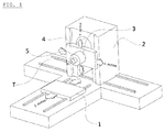
- machining centers such as the machining center, in the perspective view of FIG. 1 is shown used for machining mechanical parts.
- the illustrated machining center is, for example, with a carriage that can move horizontally in the Z-direction, and a stand that holds a tool so that it is formed in a vertical plane formed in the X and Y directions , can be moved, equipped. In this way, degrees of freedom of machining in three directions that are perpendicular to each other are achieved.
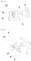
- a turntable device which has a support surface which can pivot about one or two axes.
- An appropriate structure is in FIG. 2 shown.
- the machining center is provided with 4 or 5 degrees of freedom of machining, whereby a more complicated machining is possible.
- Known turntable devices allow the inclusion of one or more processing devices or workpieces in these processing devices. In order to enable loading and unloading of the processing devices parallel to the main time, further processing devices would have to be loaded and unloaded within the processing space of the processing center while processing is being carried out on another processing device. This possibility results from new concepts, such as machining parallel to the time of day using a robot while the robot and processing room are connected. A manual loading while running Spindle is not allowed for safety reasons. Known turntable devices complicate this time-parallel loading and unloading of the processing devices, since all processing devices are arranged on a spatial plane.
- the present invention is based on the above-mentioned problems. It is an object of the invention to enable the time-parallel loading and unloading on a turntable.
- the present invention is a rotary table apparatus comprising: a receptacle for rotatably supporting a turntable and a turntable rack for rotatably supporting the cantilever-shaped receptacle.
- At least two processing devices are arranged on the receiving device, the spatial arrangement of which is designed in such a way that at least two processing devices can be alternately brought into the same spatial orientation relative to the tool by rotation about the axis of rotation. Due to the arrangement, the receiving device forms a shielding of the processing devices. Exactly this shielding effect of the recording device allows loading and unloading parallel to the main time, since, for example, machining chips can be shielded from the other clamping points by a corresponding design of the receiving device.
- the non-processing processing devices can be loaded and unloaded, which is advantageously taken over by a robot which is arranged in the processing space of the machining center or the robot cell space is combined with the processing space of the machining center.
- the rotational movement of the receiving device is controlled by the control of the machining center.
- a desired machining program can proceed.
- At least one additional turntable is used.
- This turntable is controlled by the machine control, allowing a machining program to run.
- a so-called 5-axis machining is possible. This is needed, for example, for the milling of so-called impellers or turbine wheels, since a 3-axis machining would leave undercuts on the workpiece unprocessed.
- the turntables are controlled so that they can work by means of synchronous and / or asynchronous rotation speed. This allows a turntable to stand while one or more turntables rotate. It can thus be loaded and unloaded on one turntable while working on the other turntables.
- the at least two processing devices are arranged eccentrically with respect to one another in such a way that a reverse side machining is made possible by means of at least one opening in the receiving device. This is advantageous if a reverse side machining is necessary. Then it would be disadvantageous if both processing devices were arranged concentrically with each other, which would mean that the respective rear sides would no longer be accessible.
- the receiving device is supported by an abutment.
- larger machining forces can be absorbed and there are fewer vibrations during machining.
- a rotary feedthrough for the distribution of media is arranged concentrically to the rotation axis from the turntable frame to the receiving device.
- hydraulic or pneumatic clamping elements can be used, which are acted upon via a central supply, for example via the machine with pressure.
- the receiving device is deposited in several levels.
- the rotating devices which are based on the receiving device, can be constructed correspondingly lower.
- additional shields are arranged around the receiving device.
- at least one processing device can be kept accessible to the tool in each case.
- At least one other processing device can be shielded and loaded and unloaded in this state.
- the additional shields can be alternately brought into the same spatial orientation.
- the turntable frame is integrated into the machine frame. This is mainly used in appropriately designed machines. For 3-axis machines, turntables are often placed on the machine table retrospectively.
- FIG. 1 In the perspective view FIG. 1 the structure of a machining center is shown. This representation is for better understanding and still shows no inventive design.
- FIG. 2 the structure of a machining center is shown.
- a turntable device according to the prior art. This representation is for better understanding and still shows no inventive design.
- FIG. 3 an embodiment is shown in which the processing devices (7 + 8) are arranged concentrically with each other.
- This has the advantage that with a corresponding rotation about the axis of rotation 1 (9), in this case 180 °, the processing device 2 (8) can be brought into the same spatial plane position in which the processing device 1 (7) stood before the rotation.
- the concentric arrangement of the processing devices results in the same spatial plane orientation after rotation about the rotation axis 1 (9) even the same position position relative to the machining tool (T).
- the disadvantage of the embodiment 1 is bypassed.
- the non-concentric arrangement of the processing devices (7 + 8) allows a breakthrough (13) in the receiving device (6). Through this breakthrough (13) through back processing on the workpiece (W) can be made.
- FIG. 5 Further axes of rotation are shown arranged on the receiving device (6). This results in 5 degrees of freedom, which allows a complicated processing.
- FIG. 6 shows a structure according to FIG. 5 with additional shields (15).
- additional shields (15) around the receiving device (6) arranged around so that it leaves the at least one machining device (7,8) in progress towards the tool (T) and the at least one to be loaded and unloaded processing device (7,8) shields, wherein by rotation about the axis of rotation 1 (9) the additional shields (15) can be alternately brought into the same spatial plane orientation, wherein the respective shielding additional shield (15) is preferably active so that it is in the direction of gravity on the respective processing device (7,8).
- the Rajabschrimitch (15) thus cover the non-processing processing devices (7,8), so that no machining chips or other contaminants can reach the clamping points. This ensures process-reliable, parallel-time loading. Without this provision, there could be a risk that the clamping points would be contaminated by the machining between the unloading and the new loading.
- FIG. 7 a receiving device (6) is shown, which has a stepped-off by a plurality of planes form, wherein two opposite planes are shifted parallel to each other in such a way that the processing devices (7 + 8) are closer to the rotation axis 1 (9).
- This space can be saved, since the circumscribed enveloping circle of the entire built-up on the receiving device (6) elements is thereby reduced.
Landscapes
- Engineering & Computer Science (AREA)
- Mechanical Engineering (AREA)
- Multi-Process Working Machines And Systems (AREA)
- Feeding Of Workpieces (AREA)
- Machine Tool Units (AREA)
Abstract
Description
- Die vorliegende Erfindung betrifft eine Drehtischvorrichtung gemäß dem Oberbegriff des Patentanspruchs 1. Herkömmlicherweise werden Bearbeitungszentren, wie zum Beispiel das Bearbeitungszentrum, das in der perspektivischen Ansicht von
Figur 1 gezeigt ist, zur maschinellen Bearbeitung mechanischer Teile verwendet. Das veranschaulichte Bearbeitungszentrum ist zum Beispiel mit einem Schlitten, der sich horizontal in der Z-Richtung bewegen kann, und einem Ständer, der ein Werkzeug so hält, dass es in einer vertikalen Ebene, die in der X- und der Y-Richtung gebildet wird, bewegt werden kann, ausgestattet. Auf diese Weise werden Freiheitsgrade der maschinellen Bearbeitung in drei Richtungen, die senkrecht zueinander verlaufen, erreicht. - In den vergangenen Jahren wurde auf dem Schlitten zur weiteren Erhöhung des Freiheitsgrades der maschinellen Bearbeitung zusätzlich eine Drehtischvorrichtung angeordnet, die eine Auflagefläche aufweist, die um ein oder zwei Achsen schwenken kann. Ein entsprechender Aufbau ist in
Figur 2 gezeigt. Auf diese Weise wird das Bearbeitungszentrum mit 4 bzw. 5 Freiheitsgraden der maschinellen Bearbeitung versehen, wodurch eine kompliziertere Bearbeitung möglich wird. - Bekannte Drehtischvorrichtungen ermöglichen die Aufnahme einer oder mehrerer Bearbeitungsvorrichtungen bzw. der Werkstücke in diesen Bearbeitungsvorrichtungen. Um eine hauptzeitparallele Be- und Entladung der Bearbeitungsvorrichtungen zu ermöglichen, müssten innerhalb des Bearbeitungsraumes des Bearbeitungszentrums weitere Bearbeitungsvorrichtungen be- und entladen werden, während an einer anderen Bearbeitungsvorrichtung bearbeitet wird. Diese Möglichkeit ergibt sich durch neue Konzepte, wie einer hauptzeitparallelen Bearbeitung mittels Roboter bei verbundenem Roboter- und Bearbeitungsraum. Eine manuelle Beladung, während laufender Spindel ist aus Sicherheitsgründen nicht zulässig. Bekannte Drehtischvorrichtungen erschweren dieses hauptzeitparallele Be- und Entladen der Bearbeitungsvorrichtungen, da alle Bearbeitungsvorrichtungen auf einer Raumebene angeordnet sind.
- Die vorliegende Erfindung basiert auf den oben angesprochenen Problempunkten. Es ist Aufgabe der Erfindung, die hauptzeitparallele Be- und Entladung auf einem Drehtisch zu ermöglichen.
- Dies wird mit den Merkmalen nach Schutzanspruch 1 umfänglich gelöst.
- Vorteilhafte Ausgestaltungen und Weiterbildungen der Erfindung sind in den Unteransprüchen angegeben.
- Die vorliegende Erfindung ist eine Drehtischvorrichtung, die folgendes aufweist: eine Aufnahmevorrichtung zur drehbaren Lagerung eines Drehtisches und ein Drehtischgestell zur drehbaren Lagerung der als Ausleger geformten Aufnahmevorrichtung. Auf der Aufnahmevorrichtung sind wenigstens zwei Bearbeitungsvorrichtungen angeordnet, wobei deren räumliche Anordnung zueinander derart gestaltet ist, dass durch Rotation um die Drehachse wenigstens zwei Bearbeitungsvorrichtungen abwechselnd in gleiche Raumausrichtung relativ zum Werkzeug gebracht werden können. Die Aufnahmevorrichtung bildet anordnungsbedingt eine Abschirmung der Bearbeitungsvorrichtungen. Genau diese Abschirmungswirkung der Aufnahmevorrichtung ermöglicht das hauptzeitparallele Be- und Entladen, da beispielsweise Bearbeitungsspäne durch entsprechende Bauart der Aufnahmevorrichtung von den anderen Spannstellen abgeschirmt werden können.
- Die jeweils nicht in Bearbeitung befindlichen Bearbeitungsvorrichtungen können Be- und Entladen werden, was vorteilhaft von einem Roboter übernommen wird, welcher im Bearbeitungsraum des Bearbeitungszentrums angeordnet ist bzw. dessen Roboterzellenraum mit dem Bearbeitungsraum des Bearbeitungszentrums kombiniert ist.
- Gemäß einer bevorzugten Ausgestaltung der Erfindung wird die Drehbewegung der Aufnahmevorrichtung von der Steuerung des Bearbeitungszentrums gesteuert. Somit kann ein gewünschtes Bearbeitungsprogramm ablaufen.
- Vorteilhafterweise wird wenigstens ein zusätzlicher Drehtisch verwendet. Dieser Drehtisch wird durch die Maschinensteuerung angesteuert, womit ein Bearbeitungsprogramm ablaufen kann. Somit ist eine sogenannte 5-Achs-Bearbeitung möglich. Dies wird beispielsweise für das Fräsen von sogenannten Impellern oder Turbinenrädern benötigt, da eine 3-achsige Bearbeitung Hinterschneidungen am Werkstück unbearbeitet ließe.
- Gemäß einer bevorzugten Ausgestaltung werden die Drehtische so angesteuert, dass diese mittels synchroner und/oder asynchroner Drehgeschwindigkeit arbeiten können. Hiermit wird ermöglicht, dass ein Drehtisch steht, während einer oder mehrere weitere Drehtische drehen. Es kann somit an einem Drehtisch be- und entladen werden, während an den anderen Drehtischen gearbeitet wird.
- In einer Weiterbildung der Erfindung sind die wenigstens zwei Bearbeitungsvorrichtungen derart exzentrisch zueinander angeordnet, dass eine Rückseitenbearbeitung mittels wenigstens eines Durchbruchs in der Aufnahmevorrichtung ermöglicht wird. Dies ist dann vorteilhaft, wenn eine Rückseitenbearbeitung nötig ist. Dann wäre es nachteilig, wenn beide Bearbeitungsvorrichtungen konzentrisch zueinander angeordnet wären, was zur Folge hätte, dass die jeweiligen Rückseiten nicht mehr zugänglich wären.
- Vorteilhafterweise wird die Aufnahmevorrichtung von einer Gegenlagerung abgestützt. Somit können größere Bearbeitungskräfte aufgenommen werden und es entstehen weniger Vibrationen bei der Bearbeitung.
- In einer Weiterbildung der Erfindung ist konzentrisch zur Drehachse vom Drehtischgestell zur Aufnahmevorrichtung hin eine Drehdurchführung für die Verteilung von Medien angeordnet. Mit einer solchen Drehdurchführung können beispielsweise hydraulische oder pneumatische Spannelemente eingesetzt werden, welche über eine zentrale Versorgung, beispielsweise über die Maschine mit Druck beaufschlagt werden.
- Gemäß einer bevorzugten Ausbildung der Erfindung ist die Aufnahmevorrichtung in mehreren Ebenen abgesetzt. Somit können die Drehvorrichtungen, welche auf die Aufnahmevorrichtung aufbauen, entsprechend niedriger aufgebaut werden.
- Vorteilhafterweise sind Zusatzabschirmungen um die Aufnahmevorichtung herum angeordnet. Mit solchen Zusatzabschirmungen kann jeweils wenigstens eine Bearbeitungsvorrichtung zum Werkzeug hin zugänglich gehalten werden. Wenigstens eine weitere Bearbeitungsvorrichtung kann abgeschirmt werden und in diesem Zustand be- und entladen. Durch Rotation um die erste Drehachse können die Zusatzabschirmungen abwechselnd in gleiche Raumausrichtung gebracht werden.
- In einer Weiterbildung der Erfindung ist das Drehtischgestell in das Maschinengestell integriert. Dies wird überwiegend bei entsprechend konstruierten Maschinen angewandt. Bei 3-Achs-Maschinen werden Drehtische oft nachträglich auf den Maschinentisch aufgesetzt.
- Die Erfindung wird anhand der nachfolgenden Figuren ausführlich erläutert. Es zeigen:
- Fig. 1
- eine perspektivische Darstellung eines Bearbeitungszentrums
- Fig. 2
- eine perspektivische Darstellung nach
Figur 1 mit zusätzlicher Drehtischvorrichtung - Fig. 3
- eine perspektivische Darstellung einer Drehtischvorrichtung auf einem Maschinentisch mit zwei konzentrisch zueinander stehenden Bearbeitungsvorrichtungen
- Fig. 4
- eine perspektivische Darstellung einer Drehtischvorrichtung auf einem Maschinentisch mit nicht konzentrisch zueinander stehenden Bearbeitungsvorrichtungen
- Fig. 5
- eine perspektivische Darstellung einer Drehtischvorrichtung auf einem Maschinentisch mit zwei Drehtischen auf einer Aufnahmevorrichtung
- Fig. 6
- eine perspektivische Darstellung einer Drehtischvorrichtung auf einem Maschinentisch mit Zusatzabschirmungen
- Fig. 7
- eine perspektivische Darstellung einer Drehtischvorrichtung auf einem Maschinentisch mit aufgesetzten Drehachsen, welche mittels abgesetzter Aufnahmevorrichtung zur Drehachse 1 hin verschoben sind
- In der perspektivischen Darstellung nach
Figur 1 ist der Aufbau eines Bearbeitungszentrums dargestellt. Diese Darstellung dient zum besseren Verständnis und zeigt noch keine erfindungsgemäße Ausgestaltung. - In der perspektivischen Darstellung nach
Figur 2 ist der Aufbau eines Bearbeitungszentrums dargestellt. Hier ist nun zusätzlich eine Drehtischvorrichtung nach dem Stand der Technik aufgebaut. Diese Darstellung dient zum besseren Verständnis und zeigt noch keine erfindungsgemäße Ausgestaltung. - Mit der
Figur 3 ist eine Ausführung dargestellt, bei der die Bearbeitungsvorrichtungen (7+8) konzentrisch zueinander angeordnet sind. Dies hat zum Vorteil, dass bei einer entsprechenden Drehung um die Drehachse 1 (9), hier 180°, die Bearbeitungsvorrichtung 2 (8) in gleiche räumliche Ebenenlage gebracht werden kann, in der vor der Drehung die Bearbeitungsvorrichtung 1 (7) stand. Durch die konzentrische Anordnung der Bearbeitungsvorrichtungen ergibt sich zur gleichen Raumebenenausrichtung nach der Drehung um die Drehachse 1 (9) sogar die gleiche Positionslage relativ zum Bearbeitungswerkzeug (T). - Mit Ausführungsform, wie in
Figur 4 dargestellt, wird der Nachteil der Ausführungsform 1 umgangen. Die nicht konzentrische Anordnung der Bearbeitungsvorrichtungen (7+8) ermöglicht einen Durchbruch (13) in der Aufnahmevorrichtung (6). Durch diesen Durchbruch (13) hindurch kann eine rückseitige Bearbeitung am Werkstück (W) vorgenommen werden. - In der perspektivischen Darstellung nach
Figur 5 werden weitere Drehachsen auf der Aufnahmevorrichtung (6) angeordnet gezeigt. Hiermit ergeben sich 5 Freiheitsgrade, was eine komplizierte Bearbeitung erlaubt. - Die perspektivische Darstellung nach
Figur 6 zeigt einen Aufbau gemäßFigur 5 mit Zusatzabschirmungen (15). Es sind zwei Zusatzabschirmungen (15) um die Aufnahmevorrichtung (6) herum derart angeordnet, dass diese die jeweils wenigstens eine in Bearbeitung befindliche Bearbeitungsvorrichtung (7,8) zum Werkzeug (T) hin zugänglich lässt und die wenigstens eine zu be- und entladende Bearbeitungsvorrichtung (7,8) abschirmt, wobei durch Rotation um die Drehachse 1 (9) die Zusatzabschirmungen (15) abwechselnd in gleiche Raumebenenausrichtung gebracht werden können, wobei die jeweils abschirmende Zusatzabschirmung (15) vorzugsweise derart aktiv ist, dass diese in Schwerkraftrichtung über der jeweiligen Bearbeitungsvorrichtung (7,8) steht. Die Zusatzabschrimungen (15) decken somit die nicht in Bearbeitung befindlichen Bearbeitungsvorrichtungen (7,8) ab, damit keine Bearbeitungsspäne oder sonstigen Verschmutzungen an die Spannstellen gelangen können. Hiermit wird eine prozesssichere hauptzeitparallele Beladung gewährleistet. Ohne diese Vorkehrung könnte die Gefahr bestehen, dass die Spannstellen durch die zerspanende Bearbeitung zwischen des Entladevorgangs und des neuen Beladens verschmutzt werden würden. - In der perspektivischen Darstellung nach
Figur 7 ist eine Aufnahmevorrichtung (6) gezeigt, die eine durch mehrere Ebenen abgesetzte Form aufweist, wobei zwei gegenüberliegende Ebenen derart zueinander parallel verschoben sind, dass die Bearbeitungsvorrichtungen (7+8) näher zur Drehachse 1 (9) aufgebaut sind. Hiermit kann Bauraumeingespart werden, da der umschriebene Hüll-Drehkreis der gesamten auf der Aufnahmevorrichtung (6) aufgebauten Elemente hierdurch verkleinert wird. -
- 1
- Maschinentisch
- 2
- Fahrständer
- 3
- Bearbeitungsspindel
- 4
- Spindelführung
- 5
- Werkzeugaufnahme
- 6
- Aufnahmevorrichtung
- 7
- Bearbeitungsvorrichtung 1
- 8
- Bearbeitungsvorrichtung 2
- 9
- Drehachse 1
- 10
- Drehachse 2
- 11
- Gegenlagerung
- 12
- Drehtischgestell
- 13
- Durchbruch
- 14
- Drehtisch
- 15
- Zusatzabschirmung
- T
- Werkzeug
- W
- Werkstück
Claims (10)
- Drehtischvorrichtung, aufweisend eine Aufnahmevorrichtung (6) zur Lagerung von Bearbeitungsvorrichtungen und ein Drehtischgestell (12) zur um die Drehachse 1 (9) drehbaren Lagerung der als Ausleger geformten Aufnahmevorrichtung (6),
dadurch gekennzeichnet, dass auf der Aufnahmevorrichtung (6) wenigstens zwei Bearbeitungsvorrichtungen (7+8) angeordnet sind, wobei deren räumliche Anordnung zueinander derart gestaltet ist, dass durch Rotation um die Drehachse 1 (9) wenigstens zwei Bearbeitungsvorrichtungen (7+8) abwechselnd in gleiche Raumebenenausrichtung - relativ zum Werkzeug (T) - bringbar sind, wobei die Aufnahmevorrichtung (6) eine Abschirmung der Bearbeitungsvorrichtungen gegen Verschmutzung zur hauptzeitparallelen Be- und Entladung bildet. - Drehtischvorrichtung nach Anspruch 1,
dadurch gekennzeichnet, dass die Drehbewegung der Aufnahmevorrichtung (6) von der Steuerung des Bearbeitungszentrums derart gesteuert wird, dass ein gewünschtes Bearbeitungsprogramm abläuft. - Drehtischvorrichtung nach einem der vorhergehenden Ansprüche, dadurch gekennzeichnet, dass die Bearbeitungsvorrichtungen auf jeweils einem Drehtisch (14) angeordnet sind, wobei hiermit wenigstens eine zusätzliche Drehachse 2 (10) entsteht, wobei der Drehtisch (14) durch die Steuerung des Bearbeitungszentrums angesteuert wird.
- Drehtischvorrichtung nach Anspruch 3,
dadurch gekennzeichnet, dass die Drehtische (14) mittels Ansteuerung mit synchroner und/oder asynchroner Drehgeschwindigkeiten rotieren. - Drehtischvorrichtung nach Anspruch 1,
dadurch gekennzeichnet, dass die wenigstens zwei Bearbeitungsvorrichtungen (7+8) innerhalb der Raumebene der Aufnahmevorrichtung (6) derart exzentrisch zueinander angeordnet sind, dass wenigstens ein Durchbruch (13) anordnenbar ist. - Drehtischvorrichtung nach einem der vorhergehenden Ansprüche, dadurch gekennzeichnet, dass die Aufnahmevorrichtung (6) mit einer Gegenlagerung (11) abgestützt wird.
- Drehtischvorrichtung nach einem der vorhergehenden Ansprüche, dadurch gekennzeichnet, dass konzentrisch zur Drehachse 1 (9) vom Drehtischgestell (12) zur Aufnahmevorrichtung (6) eine Drehdurchführung für die Verteilung von Medien zum Betätigen der Bearbeitungsvorrichtungen führt.
- Drehtischvorrichtung nach einem der vorhergehenden Ansprüche, dadurch gekennzeichnet, dass die Aufnahmevorrichtung (6) eine durch mehrere Ebenen abgesetzte Form aufweist, wobei wenigstens zwei gegenüberliegende Ebenen derart zueinander parallel verschoben sind, dass die Bearbeitungsvorrichtungen (7+8) näher zur Drehachse 1 (9) aufgebaut sind.
- Drehtischvorrichtung nach einem der vorhergehenden Ansprüche, dadurch gekennzeichnet, dass wenigstens zwei Zusatzabschirmungen (15) um die Aufnahmevorrichtung (6) herum derart angeordnet sind, dass diese die jeweils wenigstens eine in Bearbeitung befindliche Bearbeitungsvorrichtung zum Werkzeug (T) hin zugänglich lässt und die wenigstens eine zu be- und entladende Bearbeitungsvorrichtung abschirmt, wobei durch Rotation um die Drehachse 1 (9) die Zusatzabschirmungen (15) abwechselnd in gleiche Raumebenenausrichtung bringbar sind.
- Drehtischvorrichtung nach einem der vorhergehenden Ansprüche, dadurch gekennzeichnet, das Drehtischgestell (12) in das Maschinengestell integriert ist.
Applications Claiming Priority (4)
| Application Number | Priority Date | Filing Date | Title |
|---|---|---|---|
| DE102014114258.6A DE102014114258B4 (de) | 2014-02-21 | 2014-09-30 | Roboterzelle zum hauptzeitparallelen Be- und Entladen von Einzelplatz-Zerspanungsmaschinen sowie Vorrichtung zum Zerspanen mit einer solchen Roboterzelle |
| DE102014015583 | 2014-10-15 | ||
| DE102014015346 | 2014-10-18 | ||
| DE102015011329 | 2015-09-03 |
Publications (2)
| Publication Number | Publication Date |
|---|---|
| EP3017910A2 true EP3017910A2 (de) | 2016-05-11 |
| EP3017910A3 EP3017910A3 (de) | 2016-07-13 |
Family
ID=54324783
Family Applications (1)
| Application Number | Title | Priority Date | Filing Date |
|---|---|---|---|
| EP15020190.3A Withdrawn EP3017910A3 (de) | 2014-09-30 | 2015-10-15 | Drehtisch |
Country Status (1)
| Country | Link |
|---|---|
| EP (1) | EP3017910A3 (de) |
Cited By (4)
| Publication number | Priority date | Publication date | Assignee | Title |
|---|---|---|---|---|
| US20160167184A1 (en) * | 2013-07-29 | 2016-06-16 | Alfing Kessler Sondermaschinen Gmbh | Machine Tool Having a Workpiece Changing Device |
| US20190176278A1 (en) * | 2014-04-08 | 2019-06-13 | Etxe-Tar, S.A. | Machine tool |
| WO2021115577A1 (en) * | 2019-12-10 | 2021-06-17 | Abb Schweiz Ag | Positioning apparatus and system |
| EP4559618A1 (de) * | 2023-11-27 | 2025-05-28 | Schwäbische Werkzeugmaschinen GmbH | Werkzeugmaschine und verfahren zum betreiben einer derartigen werkzeugmaschine |
Family Cites Families (4)
| Publication number | Priority date | Publication date | Assignee | Title |
|---|---|---|---|---|
| DE19959072A1 (de) * | 1999-12-08 | 2001-06-13 | Ernst Mendrok | Werkzeugmaschine mit schwenkbaren Werkstückträgern |
| DE20212865U1 (de) * | 2002-08-22 | 2002-10-02 | Brinkmann, Johannes, Dipl.-Ing., 35745 Herborn | Vorrichtung zum Aufspannen von Werkstücken |
| US9539688B2 (en) * | 2012-06-25 | 2017-01-10 | Makino Milling Machine Co., Ltd. | Machine tool |
| EP2929979A1 (de) * | 2014-04-08 | 2015-10-14 | Etxe-Tar, S.A. | Werkzeugmaschine zur mechanischen Bearbeitung von Gestängen |
-
2015
- 2015-10-15 EP EP15020190.3A patent/EP3017910A3/de not_active Withdrawn
Non-Patent Citations (1)
| Title |
|---|
| None |
Cited By (8)
| Publication number | Priority date | Publication date | Assignee | Title |
|---|---|---|---|---|
| US20160167184A1 (en) * | 2013-07-29 | 2016-06-16 | Alfing Kessler Sondermaschinen Gmbh | Machine Tool Having a Workpiece Changing Device |
| US9914189B2 (en) * | 2013-07-29 | 2018-03-13 | Alfing Kessler Sondermaschinen Gmbh | Machine tool having a workpiece changing device |
| US20190176278A1 (en) * | 2014-04-08 | 2019-06-13 | Etxe-Tar, S.A. | Machine tool |
| US10850357B2 (en) * | 2014-04-08 | 2020-12-01 | Etxe-Tar, S.A. | Machine tool |
| WO2021115577A1 (en) * | 2019-12-10 | 2021-06-17 | Abb Schweiz Ag | Positioning apparatus and system |
| CN114746220A (zh) * | 2019-12-10 | 2022-07-12 | Abb瑞士股份有限公司 | 定位设备和系统 |
| US12558749B2 (en) | 2019-12-10 | 2026-02-24 | Abb Schweiz Ag | Positioning apparatus and system |
| EP4559618A1 (de) * | 2023-11-27 | 2025-05-28 | Schwäbische Werkzeugmaschinen GmbH | Werkzeugmaschine und verfahren zum betreiben einer derartigen werkzeugmaschine |
Also Published As
| Publication number | Publication date |
|---|---|
| EP3017910A3 (de) | 2016-07-13 |
Similar Documents
| Publication | Publication Date | Title |
|---|---|---|
| DE102007051904B3 (de) | Werkzeugmaschine | |
| DE102014114258B4 (de) | Roboterzelle zum hauptzeitparallelen Be- und Entladen von Einzelplatz-Zerspanungsmaschinen sowie Vorrichtung zum Zerspanen mit einer solchen Roboterzelle | |
| DE102015218206A1 (de) | Werkzeugmaschine, insbesondere mehrfachspindel-fräsmaschine | |
| DE102019120681B4 (de) | Werkzeugmaschine | |
| EP2945776B1 (de) | Werkzeug-maschine mit palettenwechsler | |
| EP2915622A1 (de) | Bearbeitungsmaschine, insbesondere schleifmaschine, mit einem drehbaren werkzeugmagazin | |
| DE102010051865A1 (de) | Werkzeugmaschine | |
| EP3291943B1 (de) | Werkzeugmaschine | |
| DE19800034C2 (de) | Werkzeugmaschine für Bearbeitungswerkzeuge aus der Gruppe Schleifkörper und Fräser | |
| EP1927429A1 (de) | Werkzeugmaschine mit Werkzeugmagazin | |
| DE102009050174B4 (de) | Vertikales Bearbeitungszentrum in Gantry-Bauform mit einem kreisringförmigen Werkzeugmagazin innerhalb des Bearbeitungszentrums | |
| EP2533939A1 (de) | Werkzeugmaschine mit schwenkkopf | |
| DE102016121200A1 (de) | Bearbeitungszentrum zum Bearbeiten von Werkstücken | |
| EP2161099B1 (de) | Schleifmaschine | |
| DE2411059C2 (de) | Werkzeugmaschine, insbesondere Drehmaschine, mit mindestens zwei in einem Rundschalttisch drehbar gelagerten Werkstückträgern | |
| EP2524751B1 (de) | Vertikaldrehmaschine | |
| DE102015205350A1 (de) | Vorrichtung und Verfahren zur spanenden Bearbeitung eines Werkstücks | |
| DE102015107257A1 (de) | Bearbeitungsmaschine mit Werkzeugübergabevorrichtung | |
| WO2012168489A1 (de) | Werkzeugmaschine und verfahren für eine werkzeugmaschine | |
| DE102016102952B4 (de) | Rundtakt-Werkzeugmaschine | |
| EP2928638B1 (de) | Bearbeitungsstation für bauteile | |
| DE10224577A1 (de) | Vorrichtung zur Bearbeitung von Werkstücken sowie Maschinenanordnung hierzu | |
| DE112013000290T5 (de) | Drehbearbeitungsmaschine | |
| DE102016000614A1 (de) | Transfermaschine mit Roboter zum Werkstücktransfer | |
| DE102008052540B3 (de) | Kompaktdrehmaschine |
Legal Events
| Date | Code | Title | Description |
|---|---|---|---|
| PUAI | Public reference made under article 153(3) epc to a published international application that has entered the european phase |
Free format text: ORIGINAL CODE: 0009012 |
|
| AK | Designated contracting states |
Kind code of ref document: A2 Designated state(s): AL AT BE BG CH CY CZ DE DK EE ES FI FR GB GR HR HU IE IS IT LI LT LU LV MC MK MT NL NO PL PT RO RS SE SI SK SM TR |
|
| AX | Request for extension of the european patent |
Extension state: BA ME |
|
| PUAL | Search report despatched |
Free format text: ORIGINAL CODE: 0009013 |
|
| AK | Designated contracting states |
Kind code of ref document: A3 Designated state(s): AL AT BE BG CH CY CZ DE DK EE ES FI FR GB GR HR HU IE IS IT LI LT LU LV MC MK MT NL NO PL PT RO RS SE SI SK SM TR |
|
| AX | Request for extension of the european patent |
Extension state: BA ME |
|
| RIC1 | Information provided on ipc code assigned before grant |
Ipc: B23Q 1/66 20060101ALI20160607BHEP Ipc: B23Q 7/04 20060101AFI20160607BHEP Ipc: B23Q 11/08 20060101ALI20160607BHEP Ipc: B23Q 3/06 20060101ALN20160607BHEP Ipc: B23Q 1/54 20060101ALI20160607BHEP Ipc: B25J 5/00 20060101ALI20160607BHEP Ipc: B23Q 1/48 20060101ALI20160607BHEP Ipc: B25J 21/00 20060101ALI20160607BHEP Ipc: B23Q 1/52 20060101ALI20160607BHEP |
|
| 17P | Request for examination filed |
Effective date: 20160721 |
|
| RBV | Designated contracting states (corrected) |
Designated state(s): AL AT BE BG CH CY CZ DE DK EE ES FI FR GB GR HR HU IE IS IT LI LT LU LV MC MK MT NL NO PL PT RO RS SE SI SK SM TR |
|
| 17Q | First examination report despatched |
Effective date: 20180507 |
|
| STAA | Information on the status of an ep patent application or granted ep patent |
Free format text: STATUS: THE APPLICATION IS DEEMED TO BE WITHDRAWN |
|
| 18D | Application deemed to be withdrawn |
Effective date: 20180918 |