EP3017919A2 - Configuration d'angle de redondance base sur un evenement pour un robot articule - Google Patents
Configuration d'angle de redondance base sur un evenement pour un robot articule Download PDFInfo
- Publication number
- EP3017919A2 EP3017919A2 EP15193165.6A EP15193165A EP3017919A2 EP 3017919 A2 EP3017919 A2 EP 3017919A2 EP 15193165 A EP15193165 A EP 15193165A EP 3017919 A2 EP3017919 A2 EP 3017919A2
- Authority
- EP
- European Patent Office
- Prior art keywords
- manipulator
- joint
- movement
- robot
- hinge
- Prior art date
- Legal status (The legal status is an assumption and is not a legal conclusion. Google has not performed a legal analysis and makes no representation as to the accuracy of the status listed.)
- Withdrawn
Links
Images


Classifications
-
- B—PERFORMING OPERATIONS; TRANSPORTING
- B25—HAND TOOLS; PORTABLE POWER-DRIVEN TOOLS; MANIPULATORS
- B25J—MANIPULATORS; CHAMBERS PROVIDED WITH MANIPULATION DEVICES
- B25J9/00—Program-controlled manipulators
- B25J9/06—Program-controlled manipulators characterised by multi-articulated arms
-
- B—PERFORMING OPERATIONS; TRANSPORTING
- B25—HAND TOOLS; PORTABLE POWER-DRIVEN TOOLS; MANIPULATORS
- B25J—MANIPULATORS; CHAMBERS PROVIDED WITH MANIPULATION DEVICES
- B25J9/00—Program-controlled manipulators
- B25J9/0081—Program-controlled manipulators with leader teach-in means
-
- B—PERFORMING OPERATIONS; TRANSPORTING
- B25—HAND TOOLS; PORTABLE POWER-DRIVEN TOOLS; MANIPULATORS
- B25J—MANIPULATORS; CHAMBERS PROVIDED WITH MANIPULATION DEVICES
- B25J9/00—Program-controlled manipulators
- B25J9/16—Program controls
- B25J9/1628—Program controls characterised by the control loop
- B25J9/1633—Program controls characterised by the control loop compliant, force, torque control, e.g. combined with position control
-
- B—PERFORMING OPERATIONS; TRANSPORTING
- B25—HAND TOOLS; PORTABLE POWER-DRIVEN TOOLS; MANIPULATORS
- B25J—MANIPULATORS; CHAMBERS PROVIDED WITH MANIPULATION DEVICES
- B25J9/00—Program-controlled manipulators
- B25J9/16—Program controls
- B25J9/1628—Program controls characterised by the control loop
- B25J9/1643—Program controls characterised by the control loop redundant control
-
- B—PERFORMING OPERATIONS; TRANSPORTING
- B25—HAND TOOLS; PORTABLE POWER-DRIVEN TOOLS; MANIPULATORS
- B25J—MANIPULATORS; CHAMBERS PROVIDED WITH MANIPULATION DEVICES
- B25J9/00—Program-controlled manipulators
- B25J9/16—Program controls
- B25J9/1656—Program controls characterised by programming, planning systems for manipulators
- B25J9/1664—Program controls characterised by programming, planning systems for manipulators characterised by motion, path, trajectory planning
- B25J9/1666—Avoiding collision or forbidden zones
-
- B—PERFORMING OPERATIONS; TRANSPORTING
- B25—HAND TOOLS; PORTABLE POWER-DRIVEN TOOLS; MANIPULATORS
- B25J—MANIPULATORS; CHAMBERS PROVIDED WITH MANIPULATION DEVICES
- B25J9/00—Program-controlled manipulators
- B25J9/16—Program controls
- B25J9/1674—Program controls characterised by safety, monitoring, diagnostic
-
- G—PHYSICS
- G05—CONTROLLING; REGULATING
- G05B—CONTROL OR REGULATING SYSTEMS IN GENERAL; FUNCTIONAL ELEMENTS OF SUCH SYSTEMS; MONITORING OR TESTING ARRANGEMENTS FOR SUCH SYSTEMS OR ELEMENTS
- G05B19/00—Program-control systems
- G05B19/02—Program-control systems electric
- G05B19/42—Recording and playback systems, i.e. in which the program is recorded from a cycle of operations, e.g. the cycle of operations being manually controlled, after which this record is played back on the same machine
- G05B19/423—Teaching successive positions by walk-through, i.e. the tool head or end effector being grasped and guided directly, with or without servo-assistance, to follow a path
-
- G—PHYSICS
- G05—CONTROLLING; REGULATING
- G05B—CONTROL OR REGULATING SYSTEMS IN GENERAL; FUNCTIONAL ELEMENTS OF SUCH SYSTEMS; MONITORING OR TESTING ARRANGEMENTS FOR SUCH SYSTEMS OR ELEMENTS
- G05B2219/00—Program-control systems
- G05B2219/30—Nc systems
- G05B2219/36—Nc in input of data, input key till input tape
- G05B2219/36432—By putting some constraints on some DOF, move within limited volumes, areas, planes, limits motion in x, y or z planes, virtual reality constraints
-
- G—PHYSICS
- G05—CONTROLLING; REGULATING
- G05B—CONTROL OR REGULATING SYSTEMS IN GENERAL; FUNCTIONAL ELEMENTS OF SUCH SYSTEMS; MONITORING OR TESTING ARRANGEMENTS FOR SUCH SYSTEMS OR ELEMENTS
- G05B2219/00—Program-control systems
- G05B2219/30—Nc systems
- G05B2219/39—Robotics, robotics to robotics hand
- G05B2219/39201—Control of joint stiffness
-
- G—PHYSICS
- G05—CONTROLLING; REGULATING
- G05B—CONTROL OR REGULATING SYSTEMS IN GENERAL; FUNCTIONAL ELEMENTS OF SUCH SYSTEMS; MONITORING OR TESTING ARRANGEMENTS FOR SUCH SYSTEMS OR ELEMENTS
- G05B2219/00—Program-control systems
- G05B2219/30—Nc systems
- G05B2219/40—Robotics, robotics mapping to robotics vision
- G05B2219/40365—Configuration control, select other tasks by configuration of link positions
-
- Y—GENERAL TAGGING OF NEW TECHNOLOGICAL DEVELOPMENTS; GENERAL TAGGING OF CROSS-SECTIONAL TECHNOLOGIES SPANNING OVER SEVERAL SECTIONS OF THE IPC; TECHNICAL SUBJECTS COVERED BY FORMER USPC CROSS-REFERENCE ART COLLECTIONS [XRACs] AND DIGESTS
- Y10—TECHNICAL SUBJECTS COVERED BY FORMER USPC
- Y10S—TECHNICAL SUBJECTS COVERED BY FORMER USPC CROSS-REFERENCE ART COLLECTIONS [XRACs] AND DIGESTS
- Y10S901/00—Robots
- Y10S901/02—Arm motion controller
- Y10S901/03—Teaching system
- Y10S901/04—Manual lead through
Definitions
- the present invention generally relates to a method for controlling a manipulator, in particular a hand-held multi-axis articulated arm robot, which has at least one redundant degree of freedom.
- Manipulators in particular industrial robots, are used for various work processes in, for example, assembly or production in an industrial environment.
- An industrial robot is an automatically controlled, freely programmable manipulator that can be programmed in three or more axes.
- Industrial robots can be used mobile or in a fixed location.
- An articulated robot or articulated robot, is a three-dimensional mobile industrial robot, which is composed of several hinges. Usually, the hinges are connected to arm links, and each pivot is characterized by a hinge axis. Often, articulated arm robots are equipped with six joints to map each of the six possible Cartesian degrees of freedom as possible through a hinge axis. When a robot has six or fewer degrees of freedom, the position and orientation of the individual arm members is typically uniquely defined by the position of the tool center point (TCP).
- TCP tool center point
- the seventh and each further axis is an overdetermination.
- the manipulator thus has additional degrees of freedom, which are considered redundant.
- redundant manipulators have more joint axes than Cartesian degrees of freedom.
- a manipulator with a redundant seventh axis is characterized advantageously by increased flexibility, since with fixed TCP - ie, if the position and orientation of the TCP remains unchanged in space - the manipulator can take several positions. This increased flexibility, or flexible skill, can be used, for example, for collision avoidance.
- a redundant manipulator can also assume undesired postures.
- the redundant (i.d.R., middle or elbow joint) joint can perform a redundant motion.
- this joint may unintentionally fall off or move downward and hinder the execution of later movements. This can occur, in particular, when the articulated-arm robot is hand-guided in force-compensated mode in which, for example, the effect of gravity on the limbs of the manipulator is compensated.
- an elbow joint may drift into an unfavorable area and collide with the environment or the operator.
- the articulated arm robot can come in an unfavorable attitude when handling the hand, so that the robot can be moved only by manually reorienting the elbow angle. Consequently, in this case, the operator must disadvantageously use both hands to control the robot.
- WO 2014/043702 A1 describes a system and method to restrict the movement of a robot with redundant degrees of freedom.
- the object of the present invention to provide a method and a system which allows to optimize the behavior of the elbow joint of a manipulator in the hand-held mode.
- Another object of the present invention is to prevent drifting of the posture of a redundant manipulator to an undesired position. The object is achieved by the method according to claim 1 and the manipulator system according to claim 10.
- the inventive method relates to controlling a hand-held multi-axis manipulator, such as a Gelenkarmroboters whose axes are provided with torque sensors for detecting the torques acting on the axes.
- the manipulator has at least one redundant degree of freedom.
- the manipulator can be operated in at least one of its degrees of freedom by means of compliance control, which allows a force- and / or torque-controlled operation.
- compliance control can be carried out in particular by means of an impedance control, an admittance control, a position control or a torque control.
- the hand-held manipulator is guided directly on the end effector, ie the center of the tool, and the operator concentrates only on the movement of the end effector.
- a region is defined according to the method for at least one joint of the multi-axis manipulator, in which this joint can move freely in accordance with the overall movement of the manipulator.
- the joint may move in an area defined for this joint without having to be acted upon.
- the area is defined so that a collision of the corresponding joint with the environment and / or the operator is avoided.
- the region can also be defined in such a way that movement of the corresponding joint into an unfavorable position is avoided.
- a joint has reached a limit of the area defined for the joint. It is thus determined whether, by the hand-guided movement, a joint has reached a limit of the range defined for this joint.
- the movement of the manipulator is adjusted when it has been determined that the joint has reached the limit of the area defined for the joint.
- the movement becomes adapted such that movement of the joint through the boundary is counteracted without the tool center of the manipulator is moved due to this counteracting.
- the movement of the manipulator is adjusted so that the joint can not move freely through the boundary of the area.
- the movement is thereby adapted by utilizing the redundant degree of freedom so that the tool center point of the manipulator is advantageously not moved (ie without substantial disturbance of the working process), that is not displaced or twisted or tilted.
- the position and orientation of the TCP in space thus remains essentially unchanged.
- the present invention relates to manipulators having a plurality of axes, wherein preferably all axes, and at least the axes essential for operation, can be operated with force or torque control.
- the movement of the manipulator is advantageously adjusted by the method according to the invention only when a joint has reached a range limit defined for the joint, so that otherwise the full flexibility of the redundant robot can be utilized.
- the zero space stiffness for the joint can be increased.
- a movement of the joint is counteracted, so that the joint can not slip or fall out of the permitted range into a prohibited zone.
- adjusting the movement relates precisely to that joint which has reached a boundary of the area defined for the joint. Further preferably, adjusting the movement does not affect any of the other joints.
- the manipulator has at least six axes A1-A6, more preferably at least seven axes A1-A7.
- the rigidity of the redundant joints of the axes A3 and / or A4 is changed, wherein the joints of the axes A3 and / or A4 preferably define an elbow joint of the manipulator.
- adjusting the movement includes changing the position of the joint and adjacent arms that has reached the boundary of the area defined for the joint.
- the actual position of the corresponding joint is actively commanded, thus preventing a possible collision of the joint with the environment.
- This change in position can be done alternatively or in addition to the above-described reaction possibilities for the joint, which has reached a limit.
- detecting (detecting) whether a joint of the manipulator is outside a working range defined for the joint comprises ascending and / or descending flanks.
- the signal edges are the transitions between the signal states high (H) and low (L), and are referred to as rising and falling edges.
- the detection is performed while the manipulator is hand-held in the force-compensated mode.
- the method according to the invention then corrects the posture of a redundant manipulator or adjusts the movement of individual joints when a region defined for a single joint is left.
- the procedure is such that the tool center of the manipulator is not moved or moved as a result of the adaptation, at least not such that the working process is disturbed. Consequently, the operator can continue to work undisturbed, without monitoring the attitude of the manipulator and without having to interrupt his work by the movement adjustment described.
- the manipulator system according to the invention comprising a hand-held multi-axis manipulator, in particular an articulated arm robot whose axes are provided with torque sensors for detecting the torques acting on the axles, wherein the manipulator has at least one redundant degree of freedom and has a tool center point - is provided with a control device, the Implementation of the method according to the invention is set up in order to carry out the method steps described.
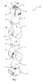
- the Fig. 1 shows a multi-unit manipulator, namely a Gelenkarmroboter 100 in an extended position and illustrates the formation of the members or arms 111, 112, 113, 114, 115, 116 and the driven and controllable or controllable axes I - VII.
- robot 100 is a lightweight robot of the type KUKA LBR III, which is installed by means of a foot 110 stationary.
- An end effector can be mounted on the hand flange 117 of the robot 100.
- a tool center is also provided by an end effector.
- the individual elements 110, 111, 112, 113, 114, 115, 116, 117 of the illustrated robot 100 are connected to one another by joints 121, 122, 123, 124, 125, 126, 127, wherein the joints can move independently of each other.
- the illustrated robot 100 has seven axes of rotation I-VII. Consequently, one of these axes is considered to be redundant compared to a sufficiently deterministic 6 DOF system. While the axes I-III form the shoulder joint of the illustrated robot 100, and axes V-VII depict a corresponding wrist, the axis IV and corresponding hinge 124 may be considered the redundant or elbow joint of the robot 100.
- the Fig. 2 shows the robot 100 in a different attitude. Unlike the in Fig. 1
- the elbow joint is now clearly kinked, and represents the highest point of the robot 100. If an operator guides the robot 100 directly to the hand flange 117, the robot 100 may move in accordance with the hand-guided motion respond and follow the lead. Due to the redundant axis, however, it is possible that the elbow joint 124 tilts down and may possibly collide with the operator. Such a redundant movement of the elbow joint as a function of the upstream and downstream joint can be described by a change in the so-called elbow angle. By the method according to the invention an unfavorable change of the elbow angle can be avoided.
- the method according to the invention can also be applied to other angles or joints, in particular if an articulated-arm robot having more than seven axes is present.
- the Fig. 3 shows a flowchart for carrying out a method 300 according to the invention.
- the process begins in step 301 where the area (or work area or work space) for the elbow joint is defined.
- the manipulator has such a posture in which the elbow joint of the manipulator is located in the area defined for the joint.
- a condition may be formulated, such as falling below a spatial distance of the elbow joint to the workspace boundary.
- step 304 the elbow joint of the manipulator approaches the boundary of the defined area. This approach is done in response to the hand-held movement of the manipulator.
- decision 305 it is checked whether the elbow joint has reached a limit of the range defined for the joint. Alternatively, at decision 305, it may be checked if the condition defined in step 303 is met.
- an isochronous message with system information is provided in step 306.
- This system information may include, but is not limited to, the current position of the manipulator and elbow, or the current elbow angle, as well as the forces and / or moments in each of the joints.
- a reaction strategy is executed.
- This reaction strategy may be one or more reactions according to decision 309, and may depend on the system information provided.
- the stiffness of the elbow joint may be increased.
- the elbow angle is toughened to prevent further fall of the elbow angle.
- the stiffness of the elbow joint can be increased in the torque control.
- a directional force application can be made to the elbow joint. The application of a force pulse is effected isochronously, so that the elbow joint is returned to the permitted range.
- the Cartesian position of the elbow joint itself may be remanded to achieve a desired position. This variant is particularly advantageous if it is to be avoided by the monitoring of the elbow that the manipulator collides with its environment.
- reaction strategies 310, 311 and 312 described are only exemplary reactions and other possible reaction strategies can be selected. Of the Programmers or operators can decide for themselves which reaction strategy to apply and whether several strategies should be combined.
- the operator may cause a reaction of the manipulator. Consequently, the adjustment of the movement of the manipulator is triggered manually, the adjustment takes place automatically even then.
- the operator can manually trigger an adjustment of the movement of the manipulator, whereupon the manipulator automatically reacts accordingly, so that a movement of a joint is counteracted by a boundary of the area defined for the joint, and without the tool center point of the manipulator is moved due to the Schmidt vomits ,
- manipulator can vary in the number and design of its members as well as its driven axes.
- the manipulator can have any number and combination of rotational and / or translational axes, so that the manipulator has at least one redundant degree of freedom.
Landscapes
- Engineering & Computer Science (AREA)
- Robotics (AREA)
- Mechanical Engineering (AREA)
- Manipulator (AREA)
- Physics & Mathematics (AREA)
- General Physics & Mathematics (AREA)
- Automation & Control Theory (AREA)
- Numerical Control (AREA)
Applications Claiming Priority (1)
| Application Number | Priority Date | Filing Date | Title |
|---|---|---|---|
| DE102014222809.3A DE102014222809B3 (de) | 2014-11-07 | 2014-11-07 | Event-basierte Redundanzwinkelkonfiguartion für Gelenkarmroboter |
Publications (2)
| Publication Number | Publication Date |
|---|---|
| EP3017919A2 true EP3017919A2 (fr) | 2016-05-11 |
| EP3017919A3 EP3017919A3 (fr) | 2016-07-20 |
Family
ID=54478597
Family Applications (1)
| Application Number | Title | Priority Date | Filing Date |
|---|---|---|---|
| EP15193165.6A Withdrawn EP3017919A3 (fr) | 2014-11-07 | 2015-11-05 | Configuration d'angle de redondance base sur un evenement pour un robot articule |
Country Status (5)
| Country | Link |
|---|---|
| US (1) | US9616564B2 (fr) |
| EP (1) | EP3017919A3 (fr) |
| KR (1) | KR101644758B1 (fr) |
| CN (1) | CN105583822B (fr) |
| DE (1) | DE102014222809B3 (fr) |
Cited By (1)
| Publication number | Priority date | Publication date | Assignee | Title |
|---|---|---|---|---|
| CN109760016A (zh) * | 2017-11-10 | 2019-05-17 | 株式会社安川电机 | 示教装置、机器人系统以及示教方法 |
Families Citing this family (29)
| Publication number | Priority date | Publication date | Assignee | Title |
|---|---|---|---|---|
| GB2523831B (en) * | 2014-03-07 | 2020-09-30 | Cmr Surgical Ltd | Surgical arm |
| EP3277467B1 (fr) * | 2015-03-31 | 2020-04-29 | ABB Schweiz AG | Procédé pour commander un robot industriel de manière tactile |
| GB2538497B (en) | 2015-05-14 | 2020-10-28 | Cmr Surgical Ltd | Torque sensing in a surgical robotic wrist |
| US9757859B1 (en) * | 2016-01-21 | 2017-09-12 | X Development Llc | Tooltip stabilization |
| US9744665B1 (en) | 2016-01-27 | 2017-08-29 | X Development Llc | Optimization of observer robot locations |
| US10059003B1 (en) | 2016-01-28 | 2018-08-28 | X Development Llc | Multi-resolution localization system |
| CN106002948B (zh) * | 2016-06-29 | 2018-04-10 | 北京空间飞行器总体设计部 | 一种空间超冗余驱动机械臂及组装方法 |
| KR102686459B1 (ko) * | 2016-12-06 | 2024-07-18 | 한화로보틱스 주식회사 | 경계면 설정 장치 및 방법 |
| JP6499701B2 (ja) * | 2017-03-30 | 2019-04-10 | ファナック株式会社 | ロボット |
| DE102017004711B4 (de) | 2017-05-16 | 2019-02-21 | Kuka Deutschland Gmbh | Robotersteuerung |
| EP3444079B1 (fr) * | 2017-08-17 | 2022-02-16 | Siemens Healthcare GmbH | Procédé et système pour faire fonctionner un robot guidé à la main |
| JP7013766B2 (ja) * | 2017-09-22 | 2022-02-01 | セイコーエプソン株式会社 | ロボット制御装置、ロボットシステム、及び制御方法 |
| DE102017011130B4 (de) | 2017-12-01 | 2021-03-04 | Kuka Deutschland Gmbh | Verfahren und System zum Steuern eines Roboters |
| CN110405749B (zh) * | 2018-04-27 | 2020-12-15 | 深圳市优必选科技有限公司 | 关节限位检测方法、装置、机器人及计算机可读存储介质 |
| CN112218595B (zh) | 2018-05-18 | 2026-04-03 | 奥瑞斯健康公司 | 用于机器人使能的远程操作的系统的控制器 |
| CN109048345A (zh) * | 2018-08-30 | 2018-12-21 | 惠州市正耀科技有限公司 | 多工位铆孔冲孔机 |
| CN109676606B (zh) * | 2018-12-29 | 2021-07-23 | 达闼机器人有限公司 | 一种计算机械臂臂角范围的方法、机械臂及机器人 |
| DE102019101072B3 (de) * | 2019-01-16 | 2020-03-12 | Franka Emika Gmbh | Unterstützen eines manuellen Führens eines Robotermanipulators |
| CN109676596B (zh) * | 2019-01-30 | 2023-09-22 | 华南理工大学 | 一种六自由度智能抓取机械臂 |
| DE102019202456B4 (de) | 2019-02-22 | 2025-07-10 | Kuka Deutschland Gmbh | Verfahren und System zum Durchführen einer vorgegebenen Aufgabe durch einen Roboter |
| DE102019118260B3 (de) | 2019-07-05 | 2020-08-20 | Franka Emika Gmbh | Taktile Rückmeldung eines Endeffektors eines Robotermanipulators über verschiedene Orientierungsbereiche |
| DE102019120157B3 (de) * | 2019-07-25 | 2020-08-20 | Franka Emika Gmbh | Verifikation eines Massemodells eines Robotermanipulators |
| WO2021155319A1 (fr) | 2020-01-29 | 2021-08-05 | Boseagle Surgical Inc. | Robots chirurgicaux endoscopiques |
| DE102021201024B3 (de) | 2021-02-04 | 2022-05-12 | Kuka Deutschland Gmbh | Verfahren und System zum Betreiben eines Roboters |
| CN113664837B (zh) * | 2021-09-18 | 2023-01-31 | 武汉联影智融医疗科技有限公司 | 机器人评价指标计算方法和机器人构型参数的寻优方法 |
| CN113894782B (zh) * | 2021-10-12 | 2023-01-17 | 华中科技大学 | 基于刚度定向的机器人铣削加工姿态优化方法及系统 |
| CN114571469B (zh) * | 2022-05-05 | 2022-07-26 | 北京科技大学 | 一种机械臂零空间实时避障控制方法及系统 |
| US12410586B2 (en) * | 2022-07-05 | 2025-09-09 | Caterpillar Inc. | Systems and methods for collision avoidance for shape changing machines |
| DE102025108325A1 (de) * | 2025-03-05 | 2026-04-02 | Schaeffler Technologies AG & Co. KG | Roboter mit integriertem Algorithmus zur Umsetzung einer Schonhaltung; sowie Verfahren zur Steuerung des Roboters |
Citations (1)
| Publication number | Priority date | Publication date | Assignee | Title |
|---|---|---|---|---|
| WO2014043702A1 (fr) | 2012-09-17 | 2014-03-20 | Rethink Robotics, Inc. | Contrainte de structures mécaniques de robots manipulateurs avec des degrés de liberté redondants |
Family Cites Families (22)
| Publication number | Priority date | Publication date | Assignee | Title |
|---|---|---|---|---|
| DE3606685A1 (de) * | 1986-02-28 | 1987-09-03 | Forsch Steuerungstechnik Der W | Vorrichtung zur handfuehrung eines industrieroboters |
| US4986724A (en) * | 1987-11-10 | 1991-01-22 | Cincinnati Milacron Inc. | System for compensated motion of coupled robot axes |
| US5297238A (en) * | 1991-08-30 | 1994-03-22 | Cimetrix Incorporated | Robot end-effector terminal control frame (TCF) calibration method and device |
| EP0850730B1 (fr) * | 1995-09-14 | 2002-07-24 | Kabushiki Kaisha Yaskawa Denki | Unite d'enseignement pour robots |
| SE0001312D0 (sv) * | 2000-04-10 | 2000-04-10 | Abb Ab | Industrirobot |
| DE10345743A1 (de) * | 2003-10-01 | 2005-05-04 | Kuka Roboter Gmbh | Verfahren und Vorrichtung zum Bestimmen von Position und Orientierung einer Bildempfangseinrichtung |
| US8676379B2 (en) | 2006-07-04 | 2014-03-18 | Panasonic Corporation | Device and method for controlling robot arm, robot, and robot arm control program |
| WO2008011845A1 (fr) * | 2006-07-28 | 2008-01-31 | Siemens Aktiengesellschaft | Compensation de la compliance dépendant de la position pour une machine-outil |
| DE102006049627A1 (de) * | 2006-10-20 | 2008-04-24 | Fraunhofer-Gesellschaft zur Förderung der angewandten Forschung e.V. | Verfahren und Vorrichtung zur Feinpositionierung eines Werkzeugs mit einer Handhabungseinrichtung |
| DE102007059480B4 (de) | 2007-12-11 | 2018-07-05 | Kuka Roboter Gmbh | Verfahren und Vorrichtung zur Posenüberwachung eines Manipulators |
| DE102007062108A1 (de) * | 2007-12-21 | 2009-07-02 | Kuka Roboter Gmbh | Industrieroboter und Verfahren zum Programmieren eines Industrieroboters |
| KR101660064B1 (ko) * | 2008-12-17 | 2016-09-26 | 쿠카 레보라토리즈 게엠베하 | 사전 결정된 경로를 매니퓰레이터가 주행하게 하기 위한 방법, 및 이러한 방법을 실행하기 위한 제어 장치 |
| EP2243602B1 (fr) * | 2009-04-22 | 2013-05-15 | KUKA Roboter GmbH | Procédé et dispositif de commande d'un manipulateur |
| JP4763074B2 (ja) * | 2009-08-03 | 2011-08-31 | ファナック株式会社 | ロボットのツール先端点の位置の計測装置および計測方法 |
| KR101633357B1 (ko) * | 2010-01-14 | 2016-06-28 | 삼성전자 주식회사 | 매니퓰레이터 및 그 제어방법 |
| DE202010005313U1 (de) * | 2010-04-27 | 2011-10-27 | Kuka Laboratories Gmbh | Bearbeitungseinrichtung |
| CN102725109B (zh) * | 2010-07-27 | 2015-03-18 | 松下电器产业株式会社 | 移动路径搜索装置及移动路径搜索方法 |
| DE102011003506A1 (de) * | 2011-02-02 | 2012-08-16 | Kuka Roboter Gmbh | Industrieroboter |
| DE102011106321A1 (de) * | 2011-07-01 | 2013-01-03 | Kuka Laboratories Gmbh | Verfahren und Steuermittel zum Steuern eines Roboters |
| DE102013012448A1 (de) * | 2013-07-26 | 2015-01-29 | Kuka Laboratories Gmbh | Verfahren und Vorrichtung zum Bremsen einer Roboterachsanordnung |
| DE102013218823A1 (de) * | 2013-09-19 | 2015-04-02 | Kuka Laboratories Gmbh | Verfahren zum manuell geführten Verstellen der Pose eines Manipulatorarms eines Industrieroboters und zugehöriger Industrieroboter |
| DE102013222456A1 (de) * | 2013-11-05 | 2015-05-07 | Kuka Laboratories Gmbh | Verfahren zum Programmieren von Bewegungsabläufen eines redundanten Industrieroboters und zugehöriger Industrieroboter |
-
2014
- 2014-11-07 DE DE102014222809.3A patent/DE102014222809B3/de active Active
-
2015
- 2015-11-02 US US14/930,529 patent/US9616564B2/en active Active
- 2015-11-04 CN CN201510738679.9A patent/CN105583822B/zh active Active
- 2015-11-05 EP EP15193165.6A patent/EP3017919A3/fr not_active Withdrawn
- 2015-11-06 KR KR1020150155685A patent/KR101644758B1/ko active Active
Patent Citations (1)
| Publication number | Priority date | Publication date | Assignee | Title |
|---|---|---|---|---|
| WO2014043702A1 (fr) | 2012-09-17 | 2014-03-20 | Rethink Robotics, Inc. | Contrainte de structures mécaniques de robots manipulateurs avec des degrés de liberté redondants |
Cited By (2)
| Publication number | Priority date | Publication date | Assignee | Title |
|---|---|---|---|---|
| CN109760016A (zh) * | 2017-11-10 | 2019-05-17 | 株式会社安川电机 | 示教装置、机器人系统以及示教方法 |
| CN109760016B (zh) * | 2017-11-10 | 2022-08-09 | 株式会社安川电机 | 示教装置、机器人系统以及示教方法 |
Also Published As
| Publication number | Publication date |
|---|---|
| DE102014222809B3 (de) | 2016-01-14 |
| US20160129588A1 (en) | 2016-05-12 |
| KR20160055077A (ko) | 2016-05-17 |
| CN105583822A (zh) | 2016-05-18 |
| CN105583822B (zh) | 2018-04-13 |
| KR101644758B1 (ko) | 2016-08-10 |
| US9616564B2 (en) | 2017-04-11 |
| EP3017919A3 (fr) | 2016-07-20 |
Similar Documents
| Publication | Publication Date | Title |
|---|---|---|
| DE102014222809B3 (de) | Event-basierte Redundanzwinkelkonfiguartion für Gelenkarmroboter | |
| EP2905111B1 (fr) | Procédé de programmation d'un robot industriel et robot industriel correspondant | |
| DE102008062622B9 (de) | Verfahren und Vorrichtung zur Befehlseingabe in eine Steuerung eines Manipulators | |
| EP2851162B1 (fr) | Procédé de réglage manuel de la pose d'un bras manipulateur d'un robot industriel et robot industriel associé | |
| EP2868445B1 (fr) | Procédé de programmation de déroulements de mouvement d'un robot industriel redondant et robot industriel associé | |
| EP2546711B2 (fr) | Procédé de programmation d'un robot | |
| EP1950010B1 (fr) | Robot et procédé de programmation d'un robot | |
| DE102011110902B4 (de) | Sicherer Betrieb eines Kraft- oder ImpedanzgesteuertenRoboters im Arbeitsraum | |
| DE102018102995B4 (de) | Robotersystem | |
| EP3323026A1 (fr) | Détermination d'une instruction d'entrée pour un robot, qui est entrée en exerçant manuellement une force sur le robot | |
| EP2359205A1 (fr) | Procédé et dispositif pour l'entrée d'une instruction dans une commande d'un manipulateur | |
| DE102007059480B4 (de) | Verfahren und Vorrichtung zur Posenüberwachung eines Manipulators | |
| DE102014226936B3 (de) | Ganzkörperimpedanz für mobile Roboter | |
| WO2016050238A1 (fr) | Procédé et dispositif de commande/régulation d'un manipulateur de robot | |
| EP1529605B1 (fr) | Procédé et système de commande des robots | |
| DE102018112370B4 (de) | Richtungsabhängige Kollisionsdetektion für einen Robotermanipulator | |
| WO2017220185A1 (fr) | Surveillance d'un ensemble robotique | |
| WO2018010842A1 (fr) | Résolution redondante pour manipulateur redondant | |
| WO2015158612A1 (fr) | Dispositif robot présentant un axe linéaire | |
| DE102017204211B4 (de) | Robotersteuerung und Robotersteuerungsverfahren | |
| DE102020107612B3 (de) | Adaptive Eingabevorrichtung | |
| DE102019118260B3 (de) | Taktile Rückmeldung eines Endeffektors eines Robotermanipulators über verschiedene Orientierungsbereiche | |
| WO2017064105A2 (fr) | Souris à axes multiples pour robot à axes multiples | |
| WO2018145917A1 (fr) | Dispositif et procédé pour le réglage du mode de conduite d'un véhicule télécommandé avec un manipulateur | |
| EP3448631A1 (fr) | Robot à support mobile et manipulateur |
Legal Events
| Date | Code | Title | Description |
|---|---|---|---|
| PUAI | Public reference made under article 153(3) epc to a published international application that has entered the european phase |
Free format text: ORIGINAL CODE: 0009012 |
|
| AK | Designated contracting states |
Kind code of ref document: A2 Designated state(s): AL AT BE BG CH CY CZ DE DK EE ES FI FR GB GR HR HU IE IS IT LI LT LU LV MC MK MT NL NO PL PT RO RS SE SI SK SM TR |
|
| AX | Request for extension of the european patent |
Extension state: BA ME |
|
| PUAL | Search report despatched |
Free format text: ORIGINAL CODE: 0009013 |
|
| AK | Designated contracting states |
Kind code of ref document: A3 Designated state(s): AL AT BE BG CH CY CZ DE DK EE ES FI FR GB GR HR HU IE IS IT LI LT LU LV MC MK MT NL NO PL PT RO RS SE SI SK SM TR |
|
| AX | Request for extension of the european patent |
Extension state: BA ME |
|
| RIC1 | Information provided on ipc code assigned before grant |
Ipc: B25J 9/16 20060101AFI20160613BHEP Ipc: B25J 9/00 20060101ALI20160613BHEP Ipc: B25J 9/06 20060101ALI20160613BHEP |
|
| 17P | Request for examination filed |
Effective date: 20170119 |
|
| RBV | Designated contracting states (corrected) |
Designated state(s): AL AT BE BG CH CY CZ DE DK EE ES FI FR GB GR HR HU IE IS IT LI LT LU LV MC MK MT NL NO PL PT RO RS SE SI SK SM TR |
|
| RAP1 | Party data changed (applicant data changed or rights of an application transferred) |
Owner name: KUKA DEUTSCHLAND GMBH |
|
| 17Q | First examination report despatched |
Effective date: 20190702 |
|
| STAA | Information on the status of an ep patent application or granted ep patent |
Free format text: STATUS: THE APPLICATION IS DEEMED TO BE WITHDRAWN |
|
| 18D | Application deemed to be withdrawn |
Effective date: 20191113 |
|
| P01 | Opt-out of the competence of the unified patent court (upc) registered |
Effective date: 20230528 |