EP3018001A2 - Systeme de paroi coulissante, structure de coffre et vehicule automobile - Google Patents
Systeme de paroi coulissante, structure de coffre et vehicule automobile Download PDFInfo
- Publication number
- EP3018001A2 EP3018001A2 EP15188307.1A EP15188307A EP3018001A2 EP 3018001 A2 EP3018001 A2 EP 3018001A2 EP 15188307 A EP15188307 A EP 15188307A EP 3018001 A2 EP3018001 A2 EP 3018001A2
- Authority
- EP
- European Patent Office
- Prior art keywords
- sliding wall
- traction means
- guide
- sliding
- drive cylinder
- Prior art date
- Legal status (The legal status is an assumption and is not a legal conclusion. Google has not performed a legal analysis and makes no representation as to the accuracy of the status listed.)
- Granted
Links
Images


Classifications
-
- B—PERFORMING OPERATIONS; TRANSPORTING
- B60—VEHICLES IN GENERAL
- B60P—VEHICLES ADAPTED FOR LOAD TRANSPORTATION OR TO TRANSPORT, TO CARRY, OR TO COMPRISE SPECIAL LOADS OR OBJECTS
- B60P1/00—Vehicles predominantly for transporting loads and modified to facilitate loading, consolidating the load, or unloading
- B60P1/006—Vehicles predominantly for transporting loads and modified to facilitate loading, consolidating the load, or unloading charge and discharge with pusher plates
-
- B—PERFORMING OPERATIONS; TRANSPORTING
- B60—VEHICLES IN GENERAL
- B60P—VEHICLES ADAPTED FOR LOAD TRANSPORTATION OR TO TRANSPORT, TO CARRY, OR TO COMPRISE SPECIAL LOADS OR OBJECTS
- B60P1/00—Vehicles predominantly for transporting loads and modified to facilitate loading, consolidating the load, or unloading
- B60P1/36—Vehicles predominantly for transporting loads and modified to facilitate loading, consolidating the load, or unloading using endless chains or belts thereon
- B60P1/365—Vehicles predominantly for transporting loads and modified to facilitate loading, consolidating the load, or unloading using endless chains or belts thereon the chains or belts being fixed to a rigid pusher plate
Definitions
- the invention relates to a sliding wall system, a cargo space structure with such a sliding wall system and a vehicle having such a cargo space structure.
- a sliding wall system comprising a sliding wall system known.
- the displacement of a wall of the sliding wall system serves to temporarily reduce the loading space bounded on one side by the wall, in order either to discharge charge stored in the loading space via a discharge opening located in the opposite direction of the displaceable wall, or to charge the load when the loading space is completely closed compacted.
- a vehicle in the form of a trailer with such a cargo space structure is for example from DE 20 2004 009 744 U1 known.
- the upwardly open cargo space is bounded by a load compartment floor, a movable end wall, a rear wall to be opened by folding up and two side walls.
- the load compartment floor is partially made of a main floor immovably integrated in the cargo space structure and a sliding floor whose length (in the direction of the displacement of the end wall) in about half of the largest distance between the sliding end wall and the rear wall and by means of a drive in the form of a Hydraulic cylinder is displaceable, formed.
- a displacement of the end wall relative to the rear wall or relative to the releasable from the rear discharge opening is carried out by moving the sliding floor including the front wall on the main floor and / or a displacement of the end wall on the sliding floor, wherein for the widest possible displacement of the end wall in the direction of Discharge both the sliding floor on the main floor and the front wall on the sliding floor must be moved.
- a side facing away from the loading space is connected to the end wall and consequently to this mitbewegter drive provided.
- This cooperates with a traction means in the form of a chain, which extends in a direction formed by the sliding floor channel on the side facing away from the loading space side of the sliding floor along the directions of movement of the end wall.
- the chain receiving channel is provided with an opening extending along its longitudinal direction through which the respective portion of the chain, which is guided in dependence on the relative position of the end wall on the sliding floor over a plurality of sprockets of the drive, is led out of the channel.
- a webbing serves to cover the opening of the channel to prevent ingress of cargo stored in the cargo space.
- the webbing is in those portions of the channel in which the chain is guided within the channel, on this and closes the opening accordingly.
- the webbing is lifted off the channel via a roller arrangement and guided over the deflection gears of the drive.
- a tensioning device for the webbing is provided.
- a trailer with a cargo space structure with sliding wall system known.
- this cargo space structure of the rotary drive by means of which the movement of the sliding wall can be effected, stationarily integrated in the load compartment structure, wherein a drive movement of the rotary drive is transmitted via a traction means on the sliding wall.
- the rotary drive is arranged at one end of the loading space structure and a deflection roller at the other end of the loading space structure.
- the traction means whose two ends are fastened to the sliding wall, is guided over both the deflection roller and the drive wheel of the rotary drive which additionally acts as a deflection.
- the traction means is in that section, in the context of the possible movement of the sliding wall on the drive wheel of the Rotary drive is guided, designed as a chain, so that the drive power of the rotary drive can be transmitted slip-free on the traction means.
- the traction means is designed as a rope.
- the present invention has the object to provide a sliding wall system for a cargo space structure of a vehicle, which allows the construction of high displacement performance for the sliding wall in a structurally advantageous and cost-effective manner.
- a load compartment structure with such a sliding wall system is the subject of claim 11.
- a vehicle comprising such a cargo space structure is the subject of claim 15.
- Advantageous embodiments of the sliding wall system according to the invention and thus of the cargo space structure and / or vehicle according to the invention are objects of the further claims and will become apparent from the following description the invention.
- the invention is based on the idea that hydraulic or pneumatic drive cylinders are characterized by low power to weight and - compared to particular hydraulic or pneumatic rotary drives with comparable performance - by low cost. Such a drive cylinder could therefore be used advantageously for generating the forces causing a displacement of the sliding wall.
- a disadvantage with the use of a drive cylinder is its comparatively small stroke or its overall length compared to the achievable stroke. According to the invention, this disadvantage is compensated by the fact that the drive of the sliding wall takes place only indirectly by means of the drive cylinder, by the movements of the movable part of the drive cylinder are transmitted via traction means on the sliding wall.
- a deflection of the traction means advantageously allows the realization of a translation less than one, in which a movement of the movable part of the drive cylinder by a defined distance to a movement of the sliding wall by a distance greater than the defined distance is leads.
- Advantageous can be a ratio of 1/2, because then the total length of the drive cylinder in the fully extended state is only slightly longer than the maximum displacement path provided for the sliding wall. The drive cylinder can thus be integrated into the load compartment structure, without this significantly surmounting a limited space on one side of the sliding wall cargo space.
- a sliding wall system for a load compartment structure comprising at least one guide, a sliding wall and a drive for sliding the sliding wall along the guide, characterized in that the drive comprises a (preferably hydraulic or pneumatic) drive cylinder, wherein a movement of a movable part ( in particular the piston rod) of the drive cylinder is transmitted in a first direction of movement via a first traction means and a movement of the movable part of the drive cylinder in a second direction of movement via a second traction means on the sliding wall.
- a (preferably hydraulic or pneumatic) drive cylinder wherein a movement of a movable part (in particular the piston rod) of the drive cylinder is transmitted in a first direction of movement via a first traction means and a movement of the movable part of the drive cylinder in a second direction of movement via a second traction means on the sliding wall.
- An inventive load compartment construction comprises, in addition to such a sliding wall system, at least one floor, the sliding wall being displaceable along the floor.
- the load compartment structure may further comprise at least one wall (side wall, roof wall), along which the sliding wall is also displaceable. It can also be provided that the sliding wall is displaceable in the direction of a discharge opening, which enables an advantageous unloading of the loading space bounded by the sliding wall and the floor and optionally the further walls by means of the sliding wall.
- a loading space formed by the load compartment structure is preferably bounded by the sliding wall and the further wall (s). Particularly preferred is an at least laterally full (ie, only upwardly open) limitation provided by walls, further preferably at least one of the walls, in particular that which is opposite the sliding wall, opened can be to release the discharge.
- the displaceable wall is preferably a rear wall in the direction of travel of a vehicle provided with the cargo space structure or (particularly preferred) at the front. But it is also possible to form at least one side wall as a sliding wall.
- one end of the first traction means is attached to the sliding wall and the other end to the guide, wherein the traction means (in particular exclusively) via a arranged on the movable part of the drive cylinder deflection (in particular deflection roller ) is guided.
- the second traction means can preferably be guided over two deflections (in particular deflection rollers) arranged outside the displacement region of the sliding wall, wherein the second traction means is also fixed to the sliding wall and guided over a deflection arranged on the movable part of the drive cylinder or on the moving part of the Fixed drive cylinder and guided over a arranged on the sliding wall deflection.
- the sliding wall is moved away from the discharge opening. Since this usually only small forces for moving the sliding wall are required, the relatively large length of the second traction device, resulting from the preferably provided multiple deflection, usually no problem in terms of excessive elongation of the second traction means is.
- the second traction means is formed inexpensively as a rope.
- the use of a rope can also provide the advantage of a relatively low weight and low operating noise.
- the first traction means over which possibly significantly higher tensile forces are transmitted, can advantageously be designed as a chain, which is better designed in comparison to a rope in terms of low elongation at high tensile forces and good deflectability.
- each of the traction means may be formed as a rope or chain.
- An embodiment of the sliding system according to the invention which is advantageous with regard to the required construction space can provide that all of the strands formed by the first and second traction means extend approximately coaxially or parallel to a longitudinal axis of the drive cylinder. This makes it possible in particular to arrange the entire drive train parallel to the sliding area for the sliding wall, whereby advantageously the great longitudinal extent of the of the Cargo space limited cargo space for the arrangement of the drive train can be exploited.
- An embodiment of the sliding wall system according to the invention in which the first traction means and the second traction means extend in parallel (spaced) planes, can also be advantageous as regards the required installation space. In particular, thereby conflicting space requirements for the at least two traction means can be avoided.
- first traction means and a second traction means are provided, wherein the second traction means is arranged with respect to the direction transverse to the directions of movement of the sliding wall between these two first traction means.
- first traction means whose elongation can be kept low.
- a symmetrical arrangement of the second traction means between two first traction means also promotes a possible symmetrical power transmission from the drive cylinder to the sliding wall on the respective traction means without it comes to space conflicts in housing the traction means.
- a tensioning device for the first traction means and / or the second traction means can be provided.
- the traction means can be biased so that a movement of the movable part of the drive cylinder is transmitted as directly as possible to the sliding wall.
- a tensioning device can be designed, for example, as a simple spring element, in particular a helical spring or threaded anchor.
- the guide is designed as a guide channel and the drive cylinder, the first traction means and / or the second traction means are at least partially disposed within the guide channel.
- This allows the powertrain to be effectively protected against the ingress of contaminants.
- this allows advantageously an embodiment of the sliding wall system as an individually manageable unit.
- these can be advantageously mounted on a structure in order to form a loading space structure according to the invention.
- an underside of the guide channel of the sliding wall system for example, placed on the floor of the structure and fixed there (eg screwed).
- this also makes it possible to design a loading space structure with a sliding wall or a sliding wall on the same or a similar basic structure as required, for example by mounting a stationary wall (instead of the sliding wall) as an alternative to a sliding wall system according to the invention.
- the sliding wall system with arranged within a guide channel drive train of the guide channel should advantageously at least opposite the loading space, more preferably as completely as possible (in particular full circumference) be formed to prevent ingress of contaminants.
- the transmission of forces from the drive train to the sliding wall must be ensured, which is preferably done mechanically by means of a fastening section.
- the guide has a guide slot, wherein the attachment portion for the sliding wall extends through the guide slot, wherein the first traction means (and the second traction means on the side facing away from the sliding wall of a guide surface engage the attachment portion.
- the guide slot wherever the mounting portion of the sliding wall is not straight is guided through the guide slot, as well as possible seals.
- the guide slot is formed between the formed as an elastically deformable cover guide surface and another element of the guide, wherein the cover is lifted by the attachment portion locally from the other element.
- a suitable cover for a loading space structure according to the invention can be inexpensively formed from a metal sheet, in particular a steel sheet. Such a cover is also characterized by a relatively good wear resistance. Also possible is the formation of the cover made of plastic or any other elastic materials.
- the mounting portion is disposed on the spaced side of the loading space of the sliding wall or below the sliding wall.
- a vehicle according to the invention comprises at least one chassis, in particular a wheel-based chassis, and a loading space structure according to the invention arranged on the chassis.
- the vehicle may in particular be a trailer.
- An embodiment in the form of a motor vehicle is also possible.
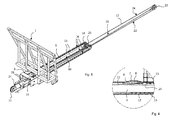
- the sliding wall system shown in the drawings comprises a sliding wall 1, a guide along which the sliding wall 1 is displaceable, and a drive train.
- the sliding wall 1 comprises a support structure made of rods and a planking not shown in the drawings on a loading space of the vehicle according to the Fig. 11 facing side of the supporting structure.
- the drive train is arranged almost completely within the guide channel 2 formed as a guide.
- the guide channel 2 having a rectangular cross-section is designed to be completely closed, ie all four sides of the guide channel 2 extending in the longitudinal direction are designed to be closed by corresponding guide wall elements.
- the two lateral guide wall elements 3 serve as guide rails, in each of which a guide carriage 4 of the sliding wall 1 is displaceably guided.
- a lower guide wall element 5 and an upper guide wall element are also provided.
- the upper guide wall element serves as a cover 6, which is connected only at its two ends fixed to the two lateral guide wall elements 3.
- the cover 6, which consists for example of a sheet steel, rests on the lateral guide wall elements 3 only with the formation of two guide slots and can thus be lifted from them locally under elastic deformation. This makes it possible to connect the sliding wall 1 arranged on one side of the cover 6 via a fastening section with components of the drive train arranged on the other side of the cover 6.
- the attachment portion comprises a cross member 7 fixing the two guide carriages 4, which is guided between the cover 6 and the lateral guide wall elements 3 and thus within the guide slots, and a fastening part 8 which is connected to the cross member 7 and located within the guide channel 2.
- an end face of the guide channel 2 is formed closed. This is the end that is at the rear of the Fig. 11 shown, the sliding wall system integrating and designed as a trailer vehicle is arranged. Only arranged at the front of the vehicle front side of the guide channel 2 is open.
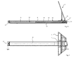
- a cylinder tube 9 of a hydraulic or pneumatic drive cylinder 10 and a guide roller 11 for a traction means 12 which is fixed to the free end of the cylinder tube 9 aligned with transversely of the vehicle axis of rotation.
- the drive cylinder 10 and the guide roller 11 are parts of the drive train, which also includes further pulleys and a total of three traction means.
- Two first traction means 13 are formed as chains. These serve to transmit an extension movement of a piston rod 14 of the drive cylinder 10 on the sliding wall 1, wherein it is provided that a movement of the Piston rod 14 is translated to the sliding wall 1 with 1/2, the sliding wall 1 thus at double speed or twice as far as the piston rod 14 is moved.
- a first end of each of the chain-shaped first traction means 13 is fixed in the region of the open end of the guide channel 2, while a second end of each second traction means 13 is fixed to the fastening part 8 of the sliding wall 1.
- the guided parallel to each other first traction means 13 are also guided over each one on the head of the piston rod 14 rotatably mounted guide roller 15, so that for each first traction means 13, two parallel runs 16 result.
- the drive cylinder 10 can be advantageously integrated with respect to the installation space in the guide channel 2, that the head of the piston rod 14 is disposed in the fully retracted state of the drive cylinder 10 approximately in the center of the intended displacement region of the sliding wall 1. As a result, the drive cylinder 10 projects out of the guide channel 2 only with a relatively short section.
- the shift range extends from the front end of the cargo space structure at the front of the vehicle according to the Fig. 11 to the rear end of the cargo space structure in the rear of the vehicle.
- the sliding wall 1 thus represents a front wall of the cargo space structure.
- the cargo space structure further comprises a bottom 17 and two side walls 18.
- the sliding wall 1, the bottom 17 and the side walls 18 define the loading space.
- the sliding wall 1 is displaceable along the bottom 17 and the side walls 18 in the direction of a discharge opening formed in the rear of the vehicle.
- the Fig. 1 to 3 . 5 and 11 show a first end position for the sliding wall 1, in which the variable of this limited cargo space is greatest. In the second end position with fully extended drive cylinder (see. Fig.
- the sliding wall 1 is located substantially directly at the discharge opening, so that the loading space is minimal.
- the sliding wall 1 can serve to convey cargo stored in the loading space in the direction of the unloading opening and out of it.
- the drive cylinder 10 is advantageous because such - in contrast to particular hydraulic or pneumatic rotary drives - characterized by a high power to weight and low costs.
- the forces required to carry the load out are transmitted via the two first traction means 13 from the piston rod 14 to the sliding wall 1.
- their training as chains with regard to the elongations occurring is advantageous because chains can be formed in a simple and cost-effective manner with high longitudinal stiffness, without this having a negative effect on the deflectability over the two pulleys 15.
- the movement or forces are transmitted via the two chain-shaped first traction means 13, this is done at a retraction of the drive cylinder 10, whereby the sliding wall 1 is moved from the rear of the vehicle or the discharge opening in the direction of the front of the vehicle , via a rope-shaped second traction means 12.
- the second traction means 12 is for this purpose with a first end in the fixing also the first ends of the chain-shaped first traction means 13 fixing part. 8 determined, for example by a clamping fixation.
- a first run 19 of the second pulling means 12 is guided to a first guide roller 20 with aligned in the vertical direction of the vehicle axis. This first guide roller 20 is not rotationally driven during a movement of the sliding wall 1.
- a second run 21 of the second pulling means 12 extends to a second guide roller 11, which is that guide roller 11, at the free end of the cylinder tube 9 of the drive cylinder 10 and thus outside of the guide channel 2 and thus of the sliding region of the sliding wall 1 is arranged.
- a third run 22 of the second pulling means 12 extends from this second guide roller 11 to a third guide roller 23, which is arranged in the region of the rear of the vehicle outside the displacement area for the side wall 1 and also has an aligned in the transverse direction of the vehicle axis of rotation. Accordingly, this third run 22 extends between two deflection rollers 11, 23 firmly integrated in the guide of the sliding wall system, so that its length does not change during the movement of the sliding wall.
- a fourth run 24 of the second pulling means 12 extends to a fourth guide roller 25 which is arranged between the two guide rollers 15 for the chain-shaped first pulling means 13 at the head of the piston rod 14 of the drive cylinder 10.
- a fifth strand 26 finally extends from the fourth deflection roller 25 to a fastening element 27 for the corresponding end of the second traction mechanism 12, which is arranged shortly before the third deflection roller 23.
- both the fifth run 26 and the fourth run 24 are extended by a distance corresponding to the stroke of the piston rod 14, whereby the desired translation of the movement of the piston rod 14 is achieved on the sliding wall 1 of 1/2. Since no load has to be moved when moving the sliding wall 1 coming from the discharge opening, the forces required for this are comparatively low.
- the second traction means 12 can be inexpensively formed as a rope. A relatively large extensibility of the rope-shaped second traction means 12, the In particular, in conjunction with the relatively large length of this traction device 12 could result in a large elongation due to the multiple deflection, is no problem because of these relatively low forces.
- the traction means 12, 13 should be biased with at least low voltage.
- a tensioning device is provided for each of the chain-shaped first traction means 13. This comprises a threaded rod 28 which is connected to one end of the respective first traction means 13 and screwed into a threaded opening of the fastening part 8, which allows a change in position of the corresponding end and thus a clamping of the associated first traction means 13.
- the rope-shaped second traction means 12 no such tensioning device is provided.
- a tensioning of the second traction means 12 is rather by the clamping and thereby stepless fixation of one end of the (held under tension during assembly) second traction means 12 in the attachment part 8 of the sliding wall 1 allows.
Landscapes
- Engineering & Computer Science (AREA)
- Transportation (AREA)
- Mechanical Engineering (AREA)
- Power-Operated Mechanisms For Wings (AREA)
- Loading Or Unloading Of Vehicles (AREA)
Applications Claiming Priority (1)
| Application Number | Priority Date | Filing Date | Title |
|---|---|---|---|
| DE201420105316 DE202014105316U1 (de) | 2014-11-05 | 2014-11-05 | Schiebewandsystem, Laderaumaufbau und Fahrzeug |
Publications (3)
| Publication Number | Publication Date |
|---|---|
| EP3018001A2 true EP3018001A2 (fr) | 2016-05-11 |
| EP3018001A3 EP3018001A3 (fr) | 2016-05-25 |
| EP3018001B1 EP3018001B1 (fr) | 2019-06-19 |
Family
ID=52106754
Family Applications (1)
| Application Number | Title | Priority Date | Filing Date |
|---|---|---|---|
| EP15188307.1A Active EP3018001B1 (fr) | 2014-11-05 | 2015-10-05 | Structure de coffre avec une système de paroi coulissante et vehicule automobile |
Country Status (6)
| Country | Link |
|---|---|
| US (1) | US9663011B2 (fr) |
| EP (1) | EP3018001B1 (fr) |
| DE (1) | DE202014105316U1 (fr) |
| DK (1) | DK3018001T3 (fr) |
| ES (1) | ES2733400T3 (fr) |
| HU (1) | HUE044425T2 (fr) |
Cited By (2)
| Publication number | Priority date | Publication date | Assignee | Title |
|---|---|---|---|---|
| DE102016113064A1 (de) | 2016-07-15 | 2018-01-18 | Bernd Icking | Entladevorrichtung |
| CN109720260A (zh) * | 2019-01-25 | 2019-05-07 | 威海顺丰专用车制造股份有限公司 | 一种散货用运输车厢及汽车 |
Families Citing this family (4)
| Publication number | Priority date | Publication date | Assignee | Title |
|---|---|---|---|---|
| CN104859512A (zh) * | 2014-12-17 | 2015-08-26 | 康昌全 | 一种便于箱体类货物装卸的车箱 |
| DE102016110138B4 (de) * | 2016-06-01 | 2020-07-09 | Fliegl Agrartechnik Gmbh | Abschiebevorrichtung und Abschiebewagen mit einer Abschiebevorrichtung |
| AU2018355890B2 (en) * | 2017-10-23 | 2021-02-11 | Denis ORLOV | Particulate material haulage arrangement |
| FI128005B (en) | 2018-07-05 | 2019-07-31 | Turf Gamechanger Oy | Lawn care device |
Citations (2)
| Publication number | Priority date | Publication date | Assignee | Title |
|---|---|---|---|---|
| DE202004009744U1 (de) | 2004-06-21 | 2004-08-19 | Fliegl, Josef | Baueinheit für einen Anhänger |
| DE202014102305U1 (de) | 2014-05-16 | 2014-06-06 | Josef Fliegl sen. | Laderaumaufbau mit einer verschiebbaren Wand und Fahrzeug mit einem solchen Laderaumaufbau |
Family Cites Families (17)
| Publication number | Priority date | Publication date | Assignee | Title |
|---|---|---|---|---|
| GB530873A (en) * | 1939-05-20 | 1940-12-24 | Atherton Brothers Ltd | Improvements in bodies for commercial vehicles |
| US2318886A (en) * | 1942-11-23 | 1943-05-11 | Paiement Joseph | Loading and unloading mechanism for trucks |
| US2505009A (en) * | 1948-12-16 | 1950-04-25 | Yale & Towne Mfg Co | Lift truck |
| US2530350A (en) * | 1949-01-08 | 1950-11-14 | Tipton Mfg Co Inc | Unloader for farm vehicles |
| US2781925A (en) * | 1954-01-27 | 1957-02-19 | Walter M Baldridge | Power operated unloading apparatus for truck bodies |
| US3021968A (en) * | 1958-12-01 | 1962-02-20 | Herbert F Myers | Load ejector mechanism for vehicle bodies |
| DE1530708A1 (de) * | 1963-07-17 | 1969-03-20 | Walter Feil | Entladevorrichtung fuer Fahrzeuge und Anhaenger |
| GB1512004A (en) * | 1974-05-10 | 1978-05-24 | Massey Ferguson Perkins Ltd | Material discharging implements |
| US4395189A (en) * | 1981-02-02 | 1983-07-26 | Munten Gerard H | Dual mast lift truck for unbalanced loads and the like |
| JPS5930762A (ja) * | 1982-08-10 | 1984-02-18 | 川崎炉材株式会社 | キヤスタブル耐火物 |
| DE9408962U1 (de) | 1994-06-01 | 1995-09-28 | Wagner, Ewald, 66606 St Wendel | Lastfahrzeug |
| GB2351063B (en) * | 1999-06-15 | 2003-08-20 | Multidrive Ltd | Load carrying body |
| NL1014489C2 (nl) | 2000-02-24 | 2001-08-28 | Cargomac B V | Transportvloer. |
| DE10058189A1 (de) | 2000-11-23 | 2002-05-29 | Claas Selbstfahr Erntemasch | Vorrichtung zum Entleeren eines Laderaumes |
| CA2709797C (fr) * | 2009-12-10 | 2013-02-12 | Harvey Stewart | Module de plancher actif leger pour remorques |
| US9371201B2 (en) * | 2011-02-17 | 2016-06-21 | A Ward Attachments Limited | Container loader |
| US20140219755A1 (en) * | 2014-04-12 | 2014-08-07 | Caterpillar Sarl | Actuating system for ejector of dump truck |
-
2014
- 2014-11-05 DE DE201420105316 patent/DE202014105316U1/de not_active Expired - Lifetime
-
2015
- 2015-10-05 ES ES15188307T patent/ES2733400T3/es active Active
- 2015-10-05 DK DK15188307.1T patent/DK3018001T3/da active
- 2015-10-05 HU HUE15188307 patent/HUE044425T2/hu unknown
- 2015-10-05 EP EP15188307.1A patent/EP3018001B1/fr active Active
- 2015-10-22 US US14/920,096 patent/US9663011B2/en active Active
Patent Citations (2)
| Publication number | Priority date | Publication date | Assignee | Title |
|---|---|---|---|---|
| DE202004009744U1 (de) | 2004-06-21 | 2004-08-19 | Fliegl, Josef | Baueinheit für einen Anhänger |
| DE202014102305U1 (de) | 2014-05-16 | 2014-06-06 | Josef Fliegl sen. | Laderaumaufbau mit einer verschiebbaren Wand und Fahrzeug mit einem solchen Laderaumaufbau |
Cited By (3)
| Publication number | Priority date | Publication date | Assignee | Title |
|---|---|---|---|---|
| DE102016113064A1 (de) | 2016-07-15 | 2018-01-18 | Bernd Icking | Entladevorrichtung |
| DE102016113064B4 (de) | 2016-07-15 | 2018-09-20 | Bernd Icking | Entladevorrichtung |
| CN109720260A (zh) * | 2019-01-25 | 2019-05-07 | 威海顺丰专用车制造股份有限公司 | 一种散货用运输车厢及汽车 |
Also Published As
| Publication number | Publication date |
|---|---|
| US9663011B2 (en) | 2017-05-30 |
| EP3018001A3 (fr) | 2016-05-25 |
| ES2733400T3 (es) | 2019-11-28 |
| DK3018001T3 (da) | 2019-07-22 |
| DE202014105316U1 (de) | 2014-11-27 |
| HUE044425T2 (hu) | 2019-10-28 |
| US20160121775A1 (en) | 2016-05-05 |
| EP3018001B1 (fr) | 2019-06-19 |
Similar Documents
| Publication | Publication Date | Title |
|---|---|---|
| EP3018001B1 (fr) | Structure de coffre avec une système de paroi coulissante et vehicule automobile | |
| DE102015214784A1 (de) | Verstellvorrichtung mit einer fremdkraftbetätigt verstellbaren Verschlussklappe | |
| DE102020117251A1 (de) | Bodenbearbeitungsmaschine mit längenveränderlicher Steigeinrichtung mit mehreren unterschiedlichen steigbereiten Betriebsstellungen | |
| DE102008020161A1 (de) | Spannvorrichtung mit verschiebbarer Spannschiene | |
| DE102015109274B3 (de) | Rolloanordnung mit Triebmittel zur Seitenführung einer Rollobahn | |
| DE102016104653A1 (de) | Doppelt teleskopierbare Bogenabstützung | |
| EP2944511A1 (fr) | Structure de coffre dotée d'une paroi coulissante et véhicule doté d'une telle structure de coffre | |
| AT516739B1 (de) | Fahrzeugaufbau | |
| EP1825082B1 (fr) | Dispositif de stationnement pour véhicules automobiles | |
| DE102022105086A1 (de) | Ausfahrbarer Leitersatz mit mehreren Leiterteilen | |
| DE2926657A1 (de) | Hubmast fuer hublader | |
| EP2010736A1 (fr) | Système de garage pour véhicules à moteur | |
| DE19528885C1 (de) | Einrichtung zum gegenläufigen Verschieben von Gabelzinken an Flurförderzeugen | |
| DE4304553C2 (de) | Hebebühne, insbesondere Kraftfahrzeug-Hebebühne | |
| EP2058172A1 (fr) | Structure d'espace de charge avec une paroi frontale mobile et véhicule de transport muni d'une telle structure | |
| DE102012001184B4 (de) | Kran mit einem Teleskopmastsystem | |
| DE588621C (de) | Verschiebbares Verdeck, insbesondere fuer Kraftwagen | |
| DE1555187C3 (de) | Vorrichtung zum Versenken eines starren Daches in den Heckraum einer Personenkraftwagenkarosserie | |
| EP1031660A1 (fr) | Poutre lisseuse | |
| DE202009006630U1 (de) | Hubvorrichtung | |
| DE602005004905T2 (de) | Steuervorrichtung zum Öffnen und Schliessen eines oben offenen Behälters für Nutzfahrzeuge | |
| DE202016105411U1 (de) | Rampenanordnung für Rollstühle zum Anbau an Fahrzeuge | |
| DE102016113064A1 (de) | Entladevorrichtung | |
| DE202005018342U1 (de) | Runge für einen Planenaufbau | |
| DE102008018032B4 (de) | Hubgerüst für ein Flurförderzeug |
Legal Events
| Date | Code | Title | Description |
|---|---|---|---|
| PUAL | Search report despatched |
Free format text: ORIGINAL CODE: 0009013 |
|
| PUAI | Public reference made under article 153(3) epc to a published international application that has entered the european phase |
Free format text: ORIGINAL CODE: 0009012 |
|
| AK | Designated contracting states |
Kind code of ref document: A2 Designated state(s): AL AT BE BG CH CY CZ DE DK EE ES FI FR GB GR HR HU IE IS IT LI LT LU LV MC MK MT NL NO PL PT RO RS SE SI SK SM TR |
|
| AX | Request for extension of the european patent |
Extension state: BA ME |
|
| AK | Designated contracting states |
Kind code of ref document: A3 Designated state(s): AL AT BE BG CH CY CZ DE DK EE ES FI FR GB GR HR HU IE IS IT LI LT LU LV MC MK MT NL NO PL PT RO RS SE SI SK SM TR |
|
| AX | Request for extension of the european patent |
Extension state: BA ME |
|
| RIC1 | Information provided on ipc code assigned before grant |
Ipc: B60P 1/00 20060101AFI20160418BHEP Ipc: B60P 1/36 20060101ALI20160418BHEP |
|
| STAA | Information on the status of an ep patent application or granted ep patent |
Free format text: STATUS: REQUEST FOR EXAMINATION WAS MADE |
|
| 17P | Request for examination filed |
Effective date: 20161109 |
|
| RBV | Designated contracting states (corrected) |
Designated state(s): AL AT BE BG CH CY CZ DE DK EE ES FI FR GB GR HR HU IE IS IT LI LT LU LV MC MK MT NL NO PL PT RO RS SE SI SK SM TR |
|
| GRAP | Despatch of communication of intention to grant a patent |
Free format text: ORIGINAL CODE: EPIDOSNIGR1 |
|
| STAA | Information on the status of an ep patent application or granted ep patent |
Free format text: STATUS: GRANT OF PATENT IS INTENDED |
|
| INTG | Intention to grant announced |
Effective date: 20190228 |
|
| GRAS | Grant fee paid |
Free format text: ORIGINAL CODE: EPIDOSNIGR3 |
|
| GRAA | (expected) grant |
Free format text: ORIGINAL CODE: 0009210 |
|
| STAA | Information on the status of an ep patent application or granted ep patent |
Free format text: STATUS: THE PATENT HAS BEEN GRANTED |
|
| AK | Designated contracting states |
Kind code of ref document: B1 Designated state(s): AL AT BE BG CH CY CZ DE DK EE ES FI FR GB GR HR HU IE IS IT LI LT LU LV MC MK MT NL NO PL PT RO RS SE SI SK SM TR |
|
| REG | Reference to a national code |
Ref country code: GB Ref legal event code: FG4D Free format text: NOT ENGLISH |
|
| REG | Reference to a national code |
Ref country code: CH Ref legal event code: EP |
|
| REG | Reference to a national code |
Ref country code: IE Ref legal event code: FG4D Free format text: LANGUAGE OF EP DOCUMENT: GERMAN |
|
| REG | Reference to a national code |
Ref country code: AT Ref legal event code: REF Ref document number: 1145059 Country of ref document: AT Kind code of ref document: T Effective date: 20190715 |
|
| REG | Reference to a national code |
Ref country code: DE Ref legal event code: R096 Ref document number: 502015009364 Country of ref document: DE |
|
| REG | Reference to a national code |
Ref country code: DK Ref legal event code: T3 Effective date: 20190717 |
|
| REG | Reference to a national code |
Ref country code: NL Ref legal event code: FP |
|
| REG | Reference to a national code |
Ref country code: HU Ref legal event code: AG4A Ref document number: E044425 Country of ref document: HU |
|
| PG25 | Lapsed in a contracting state [announced via postgrant information from national office to epo] |
Ref country code: SE Free format text: LAPSE BECAUSE OF FAILURE TO SUBMIT A TRANSLATION OF THE DESCRIPTION OR TO PAY THE FEE WITHIN THE PRESCRIBED TIME-LIMIT Effective date: 20190619 Ref country code: LT Free format text: LAPSE BECAUSE OF FAILURE TO SUBMIT A TRANSLATION OF THE DESCRIPTION OR TO PAY THE FEE WITHIN THE PRESCRIBED TIME-LIMIT Effective date: 20190619 Ref country code: AL Free format text: LAPSE BECAUSE OF FAILURE TO SUBMIT A TRANSLATION OF THE DESCRIPTION OR TO PAY THE FEE WITHIN THE PRESCRIBED TIME-LIMIT Effective date: 20190619 Ref country code: NO Free format text: LAPSE BECAUSE OF FAILURE TO SUBMIT A TRANSLATION OF THE DESCRIPTION OR TO PAY THE FEE WITHIN THE PRESCRIBED TIME-LIMIT Effective date: 20190919 Ref country code: HR Free format text: LAPSE BECAUSE OF FAILURE TO SUBMIT A TRANSLATION OF THE DESCRIPTION OR TO PAY THE FEE WITHIN THE PRESCRIBED TIME-LIMIT Effective date: 20190619 Ref country code: FI Free format text: LAPSE BECAUSE OF FAILURE TO SUBMIT A TRANSLATION OF THE DESCRIPTION OR TO PAY THE FEE WITHIN THE PRESCRIBED TIME-LIMIT Effective date: 20190619 |
|
| REG | Reference to a national code |
Ref country code: LT Ref legal event code: MG4D |
|
| REG | Reference to a national code |
Ref country code: ES Ref legal event code: FG2A Ref document number: 2733400 Country of ref document: ES Kind code of ref document: T3 Effective date: 20191128 |
|
| PG25 | Lapsed in a contracting state [announced via postgrant information from national office to epo] |
Ref country code: BG Free format text: LAPSE BECAUSE OF FAILURE TO SUBMIT A TRANSLATION OF THE DESCRIPTION OR TO PAY THE FEE WITHIN THE PRESCRIBED TIME-LIMIT Effective date: 20190919 Ref country code: RS Free format text: LAPSE BECAUSE OF FAILURE TO SUBMIT A TRANSLATION OF THE DESCRIPTION OR TO PAY THE FEE WITHIN THE PRESCRIBED TIME-LIMIT Effective date: 20190619 Ref country code: LV Free format text: LAPSE BECAUSE OF FAILURE TO SUBMIT A TRANSLATION OF THE DESCRIPTION OR TO PAY THE FEE WITHIN THE PRESCRIBED TIME-LIMIT Effective date: 20190619 Ref country code: GR Free format text: LAPSE BECAUSE OF FAILURE TO SUBMIT A TRANSLATION OF THE DESCRIPTION OR TO PAY THE FEE WITHIN THE PRESCRIBED TIME-LIMIT Effective date: 20190920 |
|
| PG25 | Lapsed in a contracting state [announced via postgrant information from national office to epo] |
Ref country code: EE Free format text: LAPSE BECAUSE OF FAILURE TO SUBMIT A TRANSLATION OF THE DESCRIPTION OR TO PAY THE FEE WITHIN THE PRESCRIBED TIME-LIMIT Effective date: 20190619 Ref country code: PT Free format text: LAPSE BECAUSE OF FAILURE TO SUBMIT A TRANSLATION OF THE DESCRIPTION OR TO PAY THE FEE WITHIN THE PRESCRIBED TIME-LIMIT Effective date: 20191021 Ref country code: SK Free format text: LAPSE BECAUSE OF FAILURE TO SUBMIT A TRANSLATION OF THE DESCRIPTION OR TO PAY THE FEE WITHIN THE PRESCRIBED TIME-LIMIT Effective date: 20190619 Ref country code: RO Free format text: LAPSE BECAUSE OF FAILURE TO SUBMIT A TRANSLATION OF THE DESCRIPTION OR TO PAY THE FEE WITHIN THE PRESCRIBED TIME-LIMIT Effective date: 20190619 |
|
| PG25 | Lapsed in a contracting state [announced via postgrant information from national office to epo] |
Ref country code: IS Free format text: LAPSE BECAUSE OF FAILURE TO SUBMIT A TRANSLATION OF THE DESCRIPTION OR TO PAY THE FEE WITHIN THE PRESCRIBED TIME-LIMIT Effective date: 20191019 Ref country code: SM Free format text: LAPSE BECAUSE OF FAILURE TO SUBMIT A TRANSLATION OF THE DESCRIPTION OR TO PAY THE FEE WITHIN THE PRESCRIBED TIME-LIMIT Effective date: 20190619 Ref country code: IT Free format text: LAPSE BECAUSE OF FAILURE TO SUBMIT A TRANSLATION OF THE DESCRIPTION OR TO PAY THE FEE WITHIN THE PRESCRIBED TIME-LIMIT Effective date: 20190619 |
|
| PG25 | Lapsed in a contracting state [announced via postgrant information from national office to epo] |
Ref country code: TR Free format text: LAPSE BECAUSE OF FAILURE TO SUBMIT A TRANSLATION OF THE DESCRIPTION OR TO PAY THE FEE WITHIN THE PRESCRIBED TIME-LIMIT Effective date: 20190619 |
|
| PG25 | Lapsed in a contracting state [announced via postgrant information from national office to epo] |
Ref country code: PL Free format text: LAPSE BECAUSE OF FAILURE TO SUBMIT A TRANSLATION OF THE DESCRIPTION OR TO PAY THE FEE WITHIN THE PRESCRIBED TIME-LIMIT Effective date: 20190619 |
|
| PG25 | Lapsed in a contracting state [announced via postgrant information from national office to epo] |
Ref country code: MC Free format text: LAPSE BECAUSE OF FAILURE TO SUBMIT A TRANSLATION OF THE DESCRIPTION OR TO PAY THE FEE WITHIN THE PRESCRIBED TIME-LIMIT Effective date: 20190619 Ref country code: IS Free format text: LAPSE BECAUSE OF FAILURE TO SUBMIT A TRANSLATION OF THE DESCRIPTION OR TO PAY THE FEE WITHIN THE PRESCRIBED TIME-LIMIT Effective date: 20200224 |
|
| REG | Reference to a national code |
Ref country code: DE Ref legal event code: R097 Ref document number: 502015009364 Country of ref document: DE |
|
| PLBE | No opposition filed within time limit |
Free format text: ORIGINAL CODE: 0009261 |
|
| STAA | Information on the status of an ep patent application or granted ep patent |
Free format text: STATUS: NO OPPOSITION FILED WITHIN TIME LIMIT |
|
| PG2D | Information on lapse in contracting state deleted |
Ref country code: IS |
|
| PG25 | Lapsed in a contracting state [announced via postgrant information from national office to epo] |
Ref country code: LU Free format text: LAPSE BECAUSE OF NON-PAYMENT OF DUE FEES Effective date: 20191005 |
|
| 26N | No opposition filed |
Effective date: 20200603 |
|
| PG25 | Lapsed in a contracting state [announced via postgrant information from national office to epo] |
Ref country code: SI Free format text: LAPSE BECAUSE OF FAILURE TO SUBMIT A TRANSLATION OF THE DESCRIPTION OR TO PAY THE FEE WITHIN THE PRESCRIBED TIME-LIMIT Effective date: 20190619 |
|
| GBPC | Gb: european patent ceased through non-payment of renewal fee |
Effective date: 20191005 |
|
| PG25 | Lapsed in a contracting state [announced via postgrant information from national office to epo] |
Ref country code: IE Free format text: LAPSE BECAUSE OF NON-PAYMENT OF DUE FEES Effective date: 20191005 Ref country code: GB Free format text: LAPSE BECAUSE OF NON-PAYMENT OF DUE FEES Effective date: 20191005 Ref country code: FR Free format text: LAPSE BECAUSE OF NON-PAYMENT OF DUE FEES Effective date: 20191031 |
|
| PG25 | Lapsed in a contracting state [announced via postgrant information from national office to epo] |
Ref country code: CY Free format text: LAPSE BECAUSE OF FAILURE TO SUBMIT A TRANSLATION OF THE DESCRIPTION OR TO PAY THE FEE WITHIN THE PRESCRIBED TIME-LIMIT Effective date: 20190619 |
|
| PG25 | Lapsed in a contracting state [announced via postgrant information from national office to epo] |
Ref country code: MT Free format text: LAPSE BECAUSE OF FAILURE TO SUBMIT A TRANSLATION OF THE DESCRIPTION OR TO PAY THE FEE WITHIN THE PRESCRIBED TIME-LIMIT Effective date: 20190619 |
|
| PG25 | Lapsed in a contracting state [announced via postgrant information from national office to epo] |
Ref country code: MK Free format text: LAPSE BECAUSE OF FAILURE TO SUBMIT A TRANSLATION OF THE DESCRIPTION OR TO PAY THE FEE WITHIN THE PRESCRIBED TIME-LIMIT Effective date: 20190619 |
|
| PGFP | Annual fee paid to national office [announced via postgrant information from national office to epo] |
Ref country code: CZ Payment date: 20250923 Year of fee payment: 11 |
|
| REG | Reference to a national code |
Ref country code: CH Ref legal event code: U11 Free format text: ST27 STATUS EVENT CODE: U-0-0-U10-U11 (AS PROVIDED BY THE NATIONAL OFFICE) Effective date: 20251101 |
|
| PGFP | Annual fee paid to national office [announced via postgrant information from national office to epo] |
Ref country code: NL Payment date: 20251023 Year of fee payment: 11 |
|
| PGFP | Annual fee paid to national office [announced via postgrant information from national office to epo] |
Ref country code: HU Payment date: 20251106 Year of fee payment: 11 |
|
| PGFP | Annual fee paid to national office [announced via postgrant information from national office to epo] |
Ref country code: DE Payment date: 20251020 Year of fee payment: 11 |
|
| PGFP | Annual fee paid to national office [announced via postgrant information from national office to epo] |
Ref country code: AT Payment date: 20251021 Year of fee payment: 11 |
|
| PGFP | Annual fee paid to national office [announced via postgrant information from national office to epo] |
Ref country code: DK Payment date: 20251023 Year of fee payment: 11 |
|
| PGFP | Annual fee paid to national office [announced via postgrant information from national office to epo] |
Ref country code: BE Payment date: 20251022 Year of fee payment: 11 |
|
| PGFP | Annual fee paid to national office [announced via postgrant information from national office to epo] |
Ref country code: CH Payment date: 20251101 Year of fee payment: 11 |
|
| PGFP | Annual fee paid to national office [announced via postgrant information from national office to epo] |
Ref country code: ES Payment date: 20251114 Year of fee payment: 11 |