EP3018081A1 - Palettenförderer für Drucker - Google Patents
Palettenförderer für Drucker Download PDFInfo
- Publication number
- EP3018081A1 EP3018081A1 EP14192123.9A EP14192123A EP3018081A1 EP 3018081 A1 EP3018081 A1 EP 3018081A1 EP 14192123 A EP14192123 A EP 14192123A EP 3018081 A1 EP3018081 A1 EP 3018081A1
- Authority
- EP
- European Patent Office
- Prior art keywords
- pallet
- train
- wagon
- pallets
- conveyor
- Prior art date
- Legal status (The legal status is an assumption and is not a legal conclusion. Google has not performed a legal analysis and makes no representation as to the accuracy of the status listed.)
- Granted
Links
Images



Classifications
-
- B—PERFORMING OPERATIONS; TRANSPORTING
- B41—PRINTING; LINING MACHINES; TYPEWRITERS; STAMPS
- B41J—TYPEWRITERS; SELECTIVE PRINTING MECHANISMS, i.e. MECHANISMS PRINTING OTHERWISE THAN FROM A FORME; CORRECTION OF TYPOGRAPHICAL ERRORS
- B41J11/00—Devices or arrangements of selective printing mechanisms, e.g. ink-jet printers or thermal printers, for supporting or handling copy material in sheet or web form
- B41J11/007—Conveyor belts or like feeding devices
-
- B—PERFORMING OPERATIONS; TRANSPORTING
- B41—PRINTING; LINING MACHINES; TYPEWRITERS; STAMPS
- B41J—TYPEWRITERS; SELECTIVE PRINTING MECHANISMS, i.e. MECHANISMS PRINTING OTHERWISE THAN FROM A FORME; CORRECTION OF TYPOGRAPHICAL ERRORS
- B41J13/00—Devices or arrangements of selective printing mechanisms, e.g. ink-jet printers or thermal printers, specially adapted for supporting or handling copy material in short lengths, e.g. sheets
- B41J13/10—Sheet holders, retainers, movable guides, or stationary guides
- B41J13/14—Aprons or guides for the printing section
-
- B—PERFORMING OPERATIONS; TRANSPORTING
- B65—CONVEYING; PACKING; STORING; HANDLING THIN OR FILAMENTARY MATERIAL
- B65H—HANDLING THIN OR FILAMENTARY MATERIAL, e.g. SHEETS, WEBS, CABLES
- B65H5/00—Feeding articles separated from piles; Feeding articles to machines
- B65H5/04—Feeding articles separated from piles; Feeding articles to machines by movable tables or carriages
-
- B—PERFORMING OPERATIONS; TRANSPORTING
- B65—CONVEYING; PACKING; STORING; HANDLING THIN OR FILAMENTARY MATERIAL
- B65G—TRANSPORT OR STORAGE DEVICES, e.g. CONVEYORS FOR LOADING OR TIPPING, SHOP CONVEYOR SYSTEMS OR PNEUMATIC TUBE CONVEYORS
- B65G37/00—Combinations of mechanical conveyors of the same kind, or of different kinds, of interest apart from their application in particular machines or use in particular manufacturing processes
-
- B—PERFORMING OPERATIONS; TRANSPORTING
- B65—CONVEYING; PACKING; STORING; HANDLING THIN OR FILAMENTARY MATERIAL
- B65H—HANDLING THIN OR FILAMENTARY MATERIAL, e.g. SHEETS, WEBS, CABLES
- B65H5/00—Feeding articles separated from piles; Feeding articles to machines
- B65H5/08—Feeding articles separated from piles; Feeding articles to machines by grippers, e.g. suction grippers
- B65H5/085—Feeding articles separated from piles; Feeding articles to machines by grippers, e.g. suction grippers by combinations of endless conveyors and grippers
-
- B—PERFORMING OPERATIONS; TRANSPORTING
- B65—CONVEYING; PACKING; STORING; HANDLING THIN OR FILAMENTARY MATERIAL
- B65H—HANDLING THIN OR FILAMENTARY MATERIAL, e.g. SHEETS, WEBS, CABLES
- B65H2402/00—Constructional details of the handling apparatus
- B65H2402/10—Modular constructions, e.g. using preformed elements or profiles
-
- B—PERFORMING OPERATIONS; TRANSPORTING
- B65—CONVEYING; PACKING; STORING; HANDLING THIN OR FILAMENTARY MATERIAL
- B65H—HANDLING THIN OR FILAMENTARY MATERIAL, e.g. SHEETS, WEBS, CABLES
- B65H2403/00—Power transmission; Driving means
- B65H2403/90—Machine drive
- B65H2403/92—Electric drive
-
- B—PERFORMING OPERATIONS; TRANSPORTING
- B65—CONVEYING; PACKING; STORING; HANDLING THIN OR FILAMENTARY MATERIAL
- B65H—HANDLING THIN OR FILAMENTARY MATERIAL, e.g. SHEETS, WEBS, CABLES
- B65H2406/00—Means using fluid
- B65H2406/30—Suction means
- B65H2406/34—Suction grippers
- B65H2406/344—Suction grippers circulating in closed loop
Definitions
- Some pallet conveyors for printers include a plurality of pallets (or bars) arranged to circulate on an endless track.
- the pallets support and move print media during printing in a print zone of the printer. Accordingly, the pallets circulate back to the print zone via a handling zone without supporting any print media.
- a controller individually controls the velocity of the pallets.
- each pallet is equipped with electromagnetic elements or magnetic responsive material so that its velocity to be individually controlled by the controller relative to the endless track.
- the velocity of the pallets is individually controlled.
- the pallets are equipped with either electromagnetic elements or with magnetic responsive material depending on the implementation.
- the pallets are equipped with motors, encoder heads and drivers in each side.
- the pallets include magnetic elements and are driven by a linear motor that is arranged along the track.
- the bill of materials (BOM) of the pallets may be high.
- the present disclosure provides solutions that at least partially reduce the BOM and improve the cost effectiveness of the pallet conveyors involved.
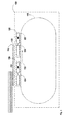
- FIG. 1 is a side view schematically illustrating an example pallet conveyor for a printer according to an implementation.
- Pallet conveyor 100 comprises a track 115 on which train pallet 122 and wagon pallet 124 circulate. Wagon pallet 124 is towed by train pallet 122.
- the train and wagon pallets may support a print substrate 110.
- train pallet 122 tows only wagon pallet 124.
- the number of wagon pallets that may be towed by a single train pallet may vary.
- a train pallet may tow a wagon pallet configuration that may comprise a single wagon pallet or a plurality of wagon pallets coupled between them in a successive manner.
- the number of wagon pallets in a wagon pallet configuration may be limited by the size or power of the driving mechanism of the train pallet. As the number of wagon pallets in a wagon pallet configuration increases the train-and-wagon configuration may become more flexible. Accordingly, a wagon pallet configuration with fewer pallets may require a train pallet with smaller driving mechanism parts, such as motors.
- the train pallet 122 may be the leading pallet of the train-and-wagon configuration 120 and the wagon pallet 124 may be the leading pallet of the wagon pallet configuration. In the example of Fig. 1 , as there is only one wagon pallet in the wagon pallet configuration, the wagon pallet is also the last pallet of the train-and-wagon configuration.
- a coupling 123 may maintain the distance between the two pallets substantially constant as the pallets circulate the endless track 115.
- the train pallet 122 may comprise at least part of the driving mechanism that provides the motive power to the train-and-wagon configuration and may be operably coupled with the track 115.
- the track 115 may be an endless track.
- the wagon pallet 124 may be merely dragged by the train pallet 122 along the endless track and may not be individually controlled.
- the pallet conveyor may include multiple train-and-wagon configurations.
- the pallet conveyor further includes train-and-wagon configuration 130.
- Train-and-wagon configuration 130 may comprise train pallet 132 coupled to wagon pallet 134 with coupling 133.
- train pallet means an active pallet bearing at least part of the driving mechanism of the train-and-wagon configuration
- wagon pallet means a passive pallet dragged or towed by a train pallet either directly or indirectly.
- a wagon pallet may be directly dragged by a train pallet when it is directly coupled to a train pallet.
- a wagon pallet may form part of a wagon pallet configuration, i.e. a series of wagon pallets coupled together.
- a particular wagon pallet may be indirectly dragged by a train pallet when it belongs to a wagon pallet configuration that is being dragged by a train pallet even though the particular wagon pallet is not directly coupled to the train pallet.
- Coupling a wagon pallet configuration to a train pallet allows for the wagon pallet configuration to comprise wagon pallets that do not have any part of driving mechanism.
- the driving mechanism may comprise at least part of a motor, drivers, controllers and encoder heads.
- By providing only the train pallet with at least part of the driving mechanism it is possible to provide a pallet conveyor for a printer with improved cost-effectiveness and with lower bill-of-materials (BOM) as compared with pallet conveyors where all pallets are individually driven.
- BOM bill-of-materials
- the encoder head may be arranged with the wagon pallet configuration. This may improve the motion accuracy as the train motor may generate some mechanical or electromagnetic noise, thus affecting the encoder head when the encoder head is arranged with the train pallet.
- FIG. 2 is a top view schematically illustrating an example pallet conveyor for a printer according to an implementation.
- Pallet conveyor 200 comprises an endless track 215 on which a plurality of pallets (222, 224, 232, 234) circulate.
- the plurality of pallets is arranged in train-and-wagon configurations (220, 230). More specifically, train-and-wagon configuration 220 comprises train pallet 222 coupled to wagon pallet 224.
- train-and-wagon configuration 220 comprises train pallet 222 coupled to wagon pallet 224.
- a coupling 223A is coupled on a first side of the train-and-wagon configuration 220.
- a first extreme of the coupling 223A is fixed to a first side of train pallet 222 and a second extreme of coupling 223A may be fixed to a first side of wagon pallet 224.
- a coupling 223B may be coupled to a second side of the train-and-wagon configuration 220.
- a first extreme of the coupling 223B may be fixed to a second side of train pallet 222 and a second extreme of coupling 223B may be fixed to a second side of wagon pallet 224.
- the couplings 223A and 223B may be rigid joints to maintain the distance between the two pallets substantially constant as the pallets circulate the endless track 215.
- the train pallet 222 may provide the motive power and may be operably coupled with the endless track 215.
- the train pallet and the endless track may be operably coupled together via a first portion disposed on each respective train pallet and a second portion disposed along a length of the track.
- One of the respective first and second portions may comprise an electromagnetic element and the other of the respective first and second portions may comprise a magnetically responsive material.
- the train pallet may comprise at least part of a driving mechanism, such as a coil motor 240A on the first side and another motor 240B on the second side.
- the track may be equipped with the rest of the driving mechanism in the form of a plurality of magnets 250 along the sides of the track.
- the train pallets 222, 232 may also comprise encoders to provide the feedback controls.
- the wagon pallet 224 may be merely dragged by the train pallet 222 along the endless track and may not be individually controlled.
- train-and-wagon configuration 230 may comprise train pallet 232 coupled to wagon pallet 234 with couplings 233A and 233B and coil motors 245A, 245B on the sides of the train pallet 232, respectively.
- the pallet conveyor 200 may also comprise a central controller 260.
- the central controller may individually control the velocity of each train-and-wagon configuration along the track by controlling the velocity of each train pallet. It may communicate wirelessly with the train pallet controllers and transfer any motion control signals. Electricity may be transferred via sliding brushes.
- the described driving mechanism is only provided as an example. One skilled in the art may appreciate that any other driving mechanism may be used to drive the train pallets.
- Each pallet may be equipped with an independent vacuum mechanism including a vacuum surface portion 270 located at a top portion of the pallets, and a vacuum source 275 to apply negative pressure or vacuum at vacuum surface portion 270 to draw and removably secure a print media against and relative to the top portion of the pallets.
- an independent vacuum mechanism including a vacuum surface portion 270 located at a top portion of the pallets, and a vacuum source 275 to apply negative pressure or vacuum at vacuum surface portion 270 to draw and removably secure a print media against and relative to the top portion of the pallets.
- pallets of a pallet conveyor may include a vacuum mechanism in which the vacuum source is located remotely from the individual pallets.
- the vacuum source may be arranged with the train pallet and may apply negative pressure or vacuum at vacuum surface portion 270 of all the pallets in the train-and-wagon configuration.
- FIG. 3 is a side view schematically illustrating an example printer according to another implementation.
- Printer 300 comprises a printing mechanism 370 and a conveyor 315 on which multiple pallets (322, 324A, 324B, 332, 334A, 334B) may circulate.
- Printing mechanism 370 may include ink supplies 375 for supplying ink to a printhead assembly 380.
- Printhead assembly 380 may include an arrangement of one or more printheads for dispensing ink on to a sheet or continuous web of paper or other print substrate 310.
- Printhead assembly 380 may be stationary with a substrate wide array of printheads or carriage mounted to scan the printhead(s) back and forth across print substrate 310.
- the multiple pallets may be arranged in train-and-wagon configurations (320, 330).
- train-and-wagon configurations 320, 330, and 340 may comprise train pallets 322, 332, and 342 coupled to wagon pallet configurations 324, 334, and 344, respectively.
- the train pallets may comprise at least part of a driving mechanism 322M, 332M and 342M.
- the train pallets may be coupled to the respective wagon pallet configurations with couplings 323, 333, 343 respectively.
- Couplings 323, 333, 343 may be rigid joints.
- the couplings may comprise a rigid central part with rotating axis on each side. The rotating axis may be fixed to the pallets and rotate with respect to the rigid central part.
- the rigid central part may comprise two openings and the rotating axis may pass through the openings and may be fixed to the pallets.
- the rotating axis may have a head having a width larger than the width of the corresponding opening of the rigid central part so that the rigid central part is maintained in position.
- the rotating axis may be fixed to the rigid central part and rotate with respect to the pallets. Then the pallets may have corresponding openings to receive the rotating axis.
- wagon pallet configurations 324, 334, 344 may comprise wagon pallets 324A, 324B, wagon pallets 334A, 334B, and wagon pallets 344A, 344B, respectively. That is, the wagon pallet configurations 324, 334, 344 may comprise 2 wagon pallets each.
- the wagon pallets of the wagon pallet configurations in the example of Fig. 3 may be coupled between them with the same type of rigid joint(s) as the one(s) used to couple the train pallet with the leading wagon pallet of the wagon pallet configuration. This allows the distance between the wagon pallets to remain steady when dragged by the respective train pallet. Accordingly, the train pallet may perceive the wagon pallet configuration as a single piece to minimize the reactive forces of the wagon pallet configuration to the respective train pallet.
- the distance between train-and-wagon configurations may vary according to the needs of the printer.
- a flexible coupling element acting as a distance limiter may be placed between a last wagon pallet of an advancing train-and-wagon configuration and a train pallet of a train-and-wagon configuration. This may limit the distance between train-and-wagon configurations to minimize the maximum gap that may be generated due to a malfunction or an error.
- a flexible coupling element 370 is placed between the wagon 324B of the train-and-wagon configuration 320 and the train pallet 332 of the train-and-wagon configuration 330.
- the flexible coupling element 370 may be in the form of an elastic joint.
- a flexible part in the middle may only allow a predetermined maximum distance (gap) between the two train-and-wagon configurations.
- some wiring may pass from one train-and-wagon configuration to another, for example power supply from sliding brushes.
- the flexible coupling element 370 may prevent damage to the passing wires in case of malfunction.
- the printer may comprise a print zone 305 wherein a portion of the pallets are to carry print media 310 along a forward track of the conveyor and a handling zone 307 to move the rest of the pallets, such as train-and-wagon configuration 340, along a return track of the conveyor to return them to the print zone.
- the printhead assembly 380 may be positioned in the print zone to print onto the print media carried by the pallets in the print zone.
- the distance maintained by the couplings between the pallets may be such that no print media may be trapped between two pallets.
- the selection of distance limiter, and therefore the distance may also depend on the flexibility of the print media to be used in the printer.
- two train-and-wagon configurations may be connected with a rigid joint, such as coupling 323.
- a rigid joint such as coupling 323.
- the motors' highest force may be required only during the transition from handling zone 307 to printing zone 305, i.e. when the train pallet is at 90° degrees with respect to the print media 310 direction, only one pallet may be at such worst position at any given time while the rest may be at lower angles, thus requiring less force. Therefore, at any given time, the rest of the pallets may not require the full force of their respective motors. Therefore, connecting two train-and-wagon configurations with a rigid joint may allow the motors of two train pallets to contribute to the driving of the 90° degrees positioned pallet. Thus, smaller or less potent motors may be used overall.
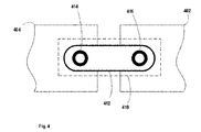
- Fig. 4 schematically illustrates a detail of a coupling between two pallets.
- Pallet 402 may be a train pallet or a wagon pallet.
- Pallet 404 may only be a wagon pallet.
- the two pallets may be coupled with a coupling 410.
- the coupling 410 may be a rigid joint. It may comprise a central rigid part 412 and two rotating axes 414, 416. Each axis may be coupled to an opening of the respective pallet. That way, the axis may rotate when the pallets do not belong to the same plane. However, the central rigid part may maintain the distance between the two pallets as they move along an endless track (not shown).
- Fig. 5 schematically illustrates a detail of a coupling between two train-and-wagon configurations.
- Train-and-wagon configuration 502 may be coupled with train-and-wagon configuration 504.
- the last wagon pallet of train-and-wagon configuration 502 may be coupled to the train pallet of train-and-wagon configuration 504.
- a flexible coupling element 510 may be fixed at one end to a side of the wagon pallet of the train-and-wagon configuration 502 and at another end to a side of the train pallet of train-and-wagon configuration 504.
- the flexible coupling element 510 may comprise a first part 512 fixedly coupled to pallet 502, a second part 514 fixedly coupled to pallet 504 and an elastic or flexible central part to allow the two connected pallets to move freely between them up to a predetermined upper limit that corresponds to a safety distance (gap) between the two pallets.
- Pallet conveyors for printers employing train-and-wagon configurations of the present invention may reduce the number of components used in the pallet conveyors and allow for a simpler construction with less maintenance needs.
- Wagon pallets may require less frequent servicing as they employ no active parts. Therefore, only train pallets may require servicing.
Landscapes
- Engineering & Computer Science (AREA)
- Mechanical Engineering (AREA)
- Ink Jet (AREA)
- Dot-Matrix Printers And Others (AREA)
- Delivering By Means Of Belts And Rollers (AREA)
- Feeding Of Articles By Means Other Than Belts Or Rollers (AREA)
Priority Applications (5)
| Application Number | Priority Date | Filing Date | Title |
|---|---|---|---|
| EP14192123.9A EP3018081B1 (de) | 2014-11-06 | 2014-11-06 | Palettenförderer für Drucker |
| JP2015201731A JP5972445B2 (ja) | 2014-11-06 | 2015-10-13 | プリンタ用のパレットコンベヤー |
| US14/918,324 US9421795B2 (en) | 2014-11-06 | 2015-10-20 | Pallet conveyors for printers |
| CN201910116629.5A CN110091629B (zh) | 2014-11-06 | 2015-11-06 | 用于打印机的托盘输送装置 |
| CN201510924958.4A CN105584232B (zh) | 2014-11-06 | 2015-11-06 | 用于打印机的托盘输送装置 |
Applications Claiming Priority (1)
| Application Number | Priority Date | Filing Date | Title |
|---|---|---|---|
| EP14192123.9A EP3018081B1 (de) | 2014-11-06 | 2014-11-06 | Palettenförderer für Drucker |
Publications (2)
| Publication Number | Publication Date |
|---|---|
| EP3018081A1 true EP3018081A1 (de) | 2016-05-11 |
| EP3018081B1 EP3018081B1 (de) | 2017-08-02 |
Family
ID=51866054
Family Applications (1)
| Application Number | Title | Priority Date | Filing Date |
|---|---|---|---|
| EP14192123.9A Active EP3018081B1 (de) | 2014-11-06 | 2014-11-06 | Palettenförderer für Drucker |
Country Status (4)
| Country | Link |
|---|---|
| US (1) | US9421795B2 (de) |
| EP (1) | EP3018081B1 (de) |
| JP (1) | JP5972445B2 (de) |
| CN (2) | CN110091629B (de) |
Cited By (1)
| Publication number | Priority date | Publication date | Assignee | Title |
|---|---|---|---|---|
| EP4707208A1 (de) * | 2024-05-15 | 2026-03-11 | MPRINT Morlock GmbH + Co. KG | Transportvorrichtung, verwendung einer transportvorrichtung und druckvorrichtung |
Families Citing this family (7)
| Publication number | Priority date | Publication date | Assignee | Title |
|---|---|---|---|---|
| EP3124263B1 (de) | 2015-07-31 | 2018-05-16 | HP Scitex Ltd | Druckmedientransportvorrichtung |
| US11072398B2 (en) * | 2016-08-12 | 2021-07-27 | Illinois Tool Works Inc. | Apparatuses and methods for high-resolution printing |
| CN109085445B (zh) * | 2016-08-18 | 2020-12-08 | 杨聪 | 避雷器试验装置 |
| CN109188133B (zh) * | 2016-08-18 | 2021-06-08 | 嵊州市雾非雾机械设备商行 | 一种避雷器试验车 |
| EP3315309B1 (de) * | 2016-10-31 | 2021-08-04 | HP Scitex Ltd | Vakuum in einem palettenförderer für ein drucksystem |
| DE102019209125A1 (de) * | 2018-07-25 | 2020-01-30 | Heidelberger Druckmaschinen Ag | Digitaldruckmaschine |
| EP3941864B1 (de) * | 2019-03-21 | 2024-04-24 | Bobst Mex Sa | Tintenstrahldruckmaschine zum bedrucken von einzelblättern |
Citations (2)
| Publication number | Priority date | Publication date | Assignee | Title |
|---|---|---|---|---|
| US20090056567A1 (en) * | 2007-08-30 | 2009-03-05 | Mimaki Engineering Co., Ltd. | Printing apparatus |
| US20130088554A1 (en) * | 2011-02-10 | 2013-04-11 | Hewlett-Packard Industrial Printing Ltd. | Pallet transfer device |
Family Cites Families (21)
| Publication number | Priority date | Publication date | Assignee | Title |
|---|---|---|---|---|
| US4430012A (en) | 1981-04-06 | 1984-02-07 | Zenith Radio Corporation | Paper guide for line printer |
| JP2690075B2 (ja) | 1986-08-21 | 1997-12-10 | 松下電送 株式会社 | カラー画像記録装置 |
| US4807790A (en) | 1986-10-10 | 1989-02-28 | Kentaro Ushioda | Paper feeding method and apparatus |
| JP2905323B2 (ja) * | 1991-11-13 | 1999-06-14 | 富士通株式会社 | 試験設備管理方式 |
| US5748483A (en) | 1994-12-13 | 1998-05-05 | Check Technology Corporation | Printing system |
| DE19622230A1 (de) | 1996-06-03 | 1997-12-04 | Schenk Gmbh | Vorrichtung zum Bedrucken von Materialien, insbesondere textilen Werkstoffen, Keramik, Papier oder dergleichen |
| US5730048A (en) * | 1997-01-06 | 1998-03-24 | Averill; Michael J. | System for the printing of small flat objects using direct rotary printing apparatus |
| US6066206A (en) | 1997-02-21 | 2000-05-23 | Speedline Technologies, Inc. | Dual track stenciling system with solder gathering head |
| US6072587A (en) | 1998-03-02 | 2000-06-06 | Accent Color Sciences, Inc. | Method of detecting position on a continuous print receiving elastic web |
| US6325480B1 (en) | 1998-07-28 | 2001-12-04 | Eastman Kodak Company | Ink jet printer and method capable of forming a plurality of registration marks on a receiver and sensing the marks formed thereby |
| JP2000158731A (ja) | 1998-11-26 | 2000-06-13 | Toppan Forms Co Ltd | 印字用シート |
| JP4422268B2 (ja) * | 2000-01-11 | 2010-02-24 | 株式会社ミヤコシ | 平板部材用の連続多色印刷装置 |
| US6948901B2 (en) | 2002-11-12 | 2005-09-27 | Metso Paper Ag | Paper roll storage and handling installation and method for storing and handling paper rolls |
| FR2853853B1 (fr) | 2003-04-15 | 2005-07-15 | Inov Media | Procede et systeme pour l'impression d'une pluralite de supports |
| JP4935418B2 (ja) * | 2006-02-27 | 2012-05-23 | ブラザー工業株式会社 | インクジェット記録装置 |
| US7722151B2 (en) | 2007-01-30 | 2010-05-25 | Hewlett-Packard Development Company, L.P. | Printing apparatus |
| JP4995670B2 (ja) * | 2007-08-30 | 2012-08-08 | 株式会社ミマキエンジニアリング | 印刷装置 |
| JP5769331B2 (ja) * | 2010-03-05 | 2015-08-26 | 日特エンジニアリング株式会社 | パレット搬送装置及びパレット搬送方法 |
| JP2011189998A (ja) * | 2010-03-12 | 2011-09-29 | Nittoku Eng Co Ltd | パレット搬送方法及びパレット搬送装置 |
| JP2012045763A (ja) * | 2010-08-25 | 2012-03-08 | Fujifilm Corp | 画像記録装置 |
| WO2012108870A1 (en) * | 2011-02-10 | 2012-08-16 | Hewlett-Packard Development Company, L.P. | Media transport assembly |
-
2014
- 2014-11-06 EP EP14192123.9A patent/EP3018081B1/de active Active
-
2015
- 2015-10-13 JP JP2015201731A patent/JP5972445B2/ja active Active
- 2015-10-20 US US14/918,324 patent/US9421795B2/en active Active
- 2015-11-06 CN CN201910116629.5A patent/CN110091629B/zh active Active
- 2015-11-06 CN CN201510924958.4A patent/CN105584232B/zh active Active
Patent Citations (2)
| Publication number | Priority date | Publication date | Assignee | Title |
|---|---|---|---|---|
| US20090056567A1 (en) * | 2007-08-30 | 2009-03-05 | Mimaki Engineering Co., Ltd. | Printing apparatus |
| US20130088554A1 (en) * | 2011-02-10 | 2013-04-11 | Hewlett-Packard Industrial Printing Ltd. | Pallet transfer device |
Cited By (1)
| Publication number | Priority date | Publication date | Assignee | Title |
|---|---|---|---|---|
| EP4707208A1 (de) * | 2024-05-15 | 2026-03-11 | MPRINT Morlock GmbH + Co. KG | Transportvorrichtung, verwendung einer transportvorrichtung und druckvorrichtung |
Also Published As
| Publication number | Publication date |
|---|---|
| CN105584232B (zh) | 2019-01-15 |
| JP2016088750A (ja) | 2016-05-23 |
| CN105584232A (zh) | 2016-05-18 |
| US9421795B2 (en) | 2016-08-23 |
| CN110091629A (zh) | 2019-08-06 |
| CN110091629B (zh) | 2020-12-04 |
| EP3018081B1 (de) | 2017-08-02 |
| JP5972445B2 (ja) | 2016-08-17 |
| US20160129699A1 (en) | 2016-05-12 |
Similar Documents
| Publication | Publication Date | Title |
|---|---|---|
| EP3018081B1 (de) | Palettenförderer für Drucker | |
| CN101171133B (zh) | 定位托架组件的系统 | |
| US8919950B2 (en) | Pallet transfer device | |
| WO2002022371A3 (en) | Tape drive and printing apparatus | |
| JP2013032007A5 (ja) | インクジェット印刷システム | |
| EP3069807B1 (de) | Bohrmaschine und verfahren zur herstellung eines gebohrten produkts | |
| US20200002118A1 (en) | Vacuum within a pallet conveyor for a printing system | |
| US20090284575A1 (en) | Moving floor media transport for digital printers | |
| CN103182858B (zh) | 上游和下游传送工具之间传送力的控制的改善的运动质量 | |
| US10189663B2 (en) | Print media transport apparatus | |
| CN109153270A (zh) | 用于印刷印刷品的设备和方法 | |
| JP2013169778A5 (de) |
Legal Events
| Date | Code | Title | Description |
|---|---|---|---|
| PUAI | Public reference made under article 153(3) epc to a published international application that has entered the european phase |
Free format text: ORIGINAL CODE: 0009012 |
|
| AK | Designated contracting states |
Kind code of ref document: A1 Designated state(s): AL AT BE BG CH CY CZ DE DK EE ES FI FR GB GR HR HU IE IS IT LI LT LU LV MC MK MT NL NO PL PT RO RS SE SI SK SM TR |
|
| AX | Request for extension of the european patent |
Extension state: BA ME |
|
| 17P | Request for examination filed |
Effective date: 20161110 |
|
| RBV | Designated contracting states (corrected) |
Designated state(s): AL AT BE BG CH CY CZ DE DK EE ES FI FR GB GR HR HU IE IS IT LI LT LU LV MC MK MT NL NO PL PT RO RS SE SI SK SM TR |
|
| GRAP | Despatch of communication of intention to grant a patent |
Free format text: ORIGINAL CODE: EPIDOSNIGR1 |
|
| RIC1 | Information provided on ipc code assigned before grant |
Ipc: B65H 5/08 20060101ALI20170223BHEP Ipc: B65H 5/04 20060101AFI20170223BHEP |
|
| INTG | Intention to grant announced |
Effective date: 20170316 |
|
| GRAS | Grant fee paid |
Free format text: ORIGINAL CODE: EPIDOSNIGR3 |
|
| GRAA | (expected) grant |
Free format text: ORIGINAL CODE: 0009210 |
|
| AK | Designated contracting states |
Kind code of ref document: B1 Designated state(s): AL AT BE BG CH CY CZ DE DK EE ES FI FR GB GR HR HU IE IS IT LI LT LU LV MC MK MT NL NO PL PT RO RS SE SI SK SM TR |
|
| REG | Reference to a national code |
Ref country code: CH Ref legal event code: EP Ref country code: AT Ref legal event code: REF Ref document number: 914206 Country of ref document: AT Kind code of ref document: T Effective date: 20170815 |
|
| REG | Reference to a national code |
Ref country code: IE Ref legal event code: FG4D |
|
| REG | Reference to a national code |
Ref country code: DE Ref legal event code: R096 Ref document number: 602014012463 Country of ref document: DE |
|
| REG | Reference to a national code |
Ref country code: FR Ref legal event code: PLFP Year of fee payment: 4 |
|
| REG | Reference to a national code |
Ref country code: NL Ref legal event code: MP Effective date: 20170802 |
|
| REG | Reference to a national code |
Ref country code: AT Ref legal event code: MK05 Ref document number: 914206 Country of ref document: AT Kind code of ref document: T Effective date: 20170802 |
|
| REG | Reference to a national code |
Ref country code: LT Ref legal event code: MG4D |
|
| PG25 | Lapsed in a contracting state [announced via postgrant information from national office to epo] |
Ref country code: LT Free format text: LAPSE BECAUSE OF FAILURE TO SUBMIT A TRANSLATION OF THE DESCRIPTION OR TO PAY THE FEE WITHIN THE PRESCRIBED TIME-LIMIT Effective date: 20170802 Ref country code: NL Free format text: LAPSE BECAUSE OF FAILURE TO SUBMIT A TRANSLATION OF THE DESCRIPTION OR TO PAY THE FEE WITHIN THE PRESCRIBED TIME-LIMIT Effective date: 20170802 Ref country code: FI Free format text: LAPSE BECAUSE OF FAILURE TO SUBMIT A TRANSLATION OF THE DESCRIPTION OR TO PAY THE FEE WITHIN THE PRESCRIBED TIME-LIMIT Effective date: 20170802 Ref country code: HR Free format text: LAPSE BECAUSE OF FAILURE TO SUBMIT A TRANSLATION OF THE DESCRIPTION OR TO PAY THE FEE WITHIN THE PRESCRIBED TIME-LIMIT Effective date: 20170802 Ref country code: SE Free format text: LAPSE BECAUSE OF FAILURE TO SUBMIT A TRANSLATION OF THE DESCRIPTION OR TO PAY THE FEE WITHIN THE PRESCRIBED TIME-LIMIT Effective date: 20170802 Ref country code: NO Free format text: LAPSE BECAUSE OF FAILURE TO SUBMIT A TRANSLATION OF THE DESCRIPTION OR TO PAY THE FEE WITHIN THE PRESCRIBED TIME-LIMIT Effective date: 20171102 Ref country code: AT Free format text: LAPSE BECAUSE OF FAILURE TO SUBMIT A TRANSLATION OF THE DESCRIPTION OR TO PAY THE FEE WITHIN THE PRESCRIBED TIME-LIMIT Effective date: 20170802 |
|
| PG25 | Lapsed in a contracting state [announced via postgrant information from national office to epo] |
Ref country code: GR Free format text: LAPSE BECAUSE OF FAILURE TO SUBMIT A TRANSLATION OF THE DESCRIPTION OR TO PAY THE FEE WITHIN THE PRESCRIBED TIME-LIMIT Effective date: 20171103 Ref country code: IS Free format text: LAPSE BECAUSE OF FAILURE TO SUBMIT A TRANSLATION OF THE DESCRIPTION OR TO PAY THE FEE WITHIN THE PRESCRIBED TIME-LIMIT Effective date: 20171202 Ref country code: PL Free format text: LAPSE BECAUSE OF FAILURE TO SUBMIT A TRANSLATION OF THE DESCRIPTION OR TO PAY THE FEE WITHIN THE PRESCRIBED TIME-LIMIT Effective date: 20170802 Ref country code: BG Free format text: LAPSE BECAUSE OF FAILURE TO SUBMIT A TRANSLATION OF THE DESCRIPTION OR TO PAY THE FEE WITHIN THE PRESCRIBED TIME-LIMIT Effective date: 20171102 Ref country code: LV Free format text: LAPSE BECAUSE OF FAILURE TO SUBMIT A TRANSLATION OF THE DESCRIPTION OR TO PAY THE FEE WITHIN THE PRESCRIBED TIME-LIMIT Effective date: 20170802 Ref country code: RS Free format text: LAPSE BECAUSE OF FAILURE TO SUBMIT A TRANSLATION OF THE DESCRIPTION OR TO PAY THE FEE WITHIN THE PRESCRIBED TIME-LIMIT Effective date: 20170802 Ref country code: ES Free format text: LAPSE BECAUSE OF FAILURE TO SUBMIT A TRANSLATION OF THE DESCRIPTION OR TO PAY THE FEE WITHIN THE PRESCRIBED TIME-LIMIT Effective date: 20170802 |
|
| PG25 | Lapsed in a contracting state [announced via postgrant information from national office to epo] |
Ref country code: RO Free format text: LAPSE BECAUSE OF FAILURE TO SUBMIT A TRANSLATION OF THE DESCRIPTION OR TO PAY THE FEE WITHIN THE PRESCRIBED TIME-LIMIT Effective date: 20170802 Ref country code: DK Free format text: LAPSE BECAUSE OF FAILURE TO SUBMIT A TRANSLATION OF THE DESCRIPTION OR TO PAY THE FEE WITHIN THE PRESCRIBED TIME-LIMIT Effective date: 20170802 Ref country code: CZ Free format text: LAPSE BECAUSE OF FAILURE TO SUBMIT A TRANSLATION OF THE DESCRIPTION OR TO PAY THE FEE WITHIN THE PRESCRIBED TIME-LIMIT Effective date: 20170802 |
|
| REG | Reference to a national code |
Ref country code: DE Ref legal event code: R097 Ref document number: 602014012463 Country of ref document: DE |
|
| PG25 | Lapsed in a contracting state [announced via postgrant information from national office to epo] |
Ref country code: EE Free format text: LAPSE BECAUSE OF FAILURE TO SUBMIT A TRANSLATION OF THE DESCRIPTION OR TO PAY THE FEE WITHIN THE PRESCRIBED TIME-LIMIT Effective date: 20170802 Ref country code: IT Free format text: LAPSE BECAUSE OF FAILURE TO SUBMIT A TRANSLATION OF THE DESCRIPTION OR TO PAY THE FEE WITHIN THE PRESCRIBED TIME-LIMIT Effective date: 20170802 Ref country code: SM Free format text: LAPSE BECAUSE OF FAILURE TO SUBMIT A TRANSLATION OF THE DESCRIPTION OR TO PAY THE FEE WITHIN THE PRESCRIBED TIME-LIMIT Effective date: 20170802 Ref country code: SK Free format text: LAPSE BECAUSE OF FAILURE TO SUBMIT A TRANSLATION OF THE DESCRIPTION OR TO PAY THE FEE WITHIN THE PRESCRIBED TIME-LIMIT Effective date: 20170802 |
|
| PLBE | No opposition filed within time limit |
Free format text: ORIGINAL CODE: 0009261 |
|
| STAA | Information on the status of an ep patent application or granted ep patent |
Free format text: STATUS: NO OPPOSITION FILED WITHIN TIME LIMIT |
|
| PG25 | Lapsed in a contracting state [announced via postgrant information from national office to epo] |
Ref country code: MC Free format text: LAPSE BECAUSE OF FAILURE TO SUBMIT A TRANSLATION OF THE DESCRIPTION OR TO PAY THE FEE WITHIN THE PRESCRIBED TIME-LIMIT Effective date: 20170802 |
|
| 26N | No opposition filed |
Effective date: 20180503 |
|
| PG25 | Lapsed in a contracting state [announced via postgrant information from national office to epo] |
Ref country code: CH Free format text: LAPSE BECAUSE OF NON-PAYMENT OF DUE FEES Effective date: 20171130 Ref country code: LI Free format text: LAPSE BECAUSE OF NON-PAYMENT OF DUE FEES Effective date: 20171130 |
|
| PG25 | Lapsed in a contracting state [announced via postgrant information from national office to epo] |
Ref country code: SI Free format text: LAPSE BECAUSE OF FAILURE TO SUBMIT A TRANSLATION OF THE DESCRIPTION OR TO PAY THE FEE WITHIN THE PRESCRIBED TIME-LIMIT Effective date: 20170802 Ref country code: LU Free format text: LAPSE BECAUSE OF NON-PAYMENT OF DUE FEES Effective date: 20171106 |
|
| REG | Reference to a national code |
Ref country code: BE Ref legal event code: MM Effective date: 20171130 |
|
| REG | Reference to a national code |
Ref country code: IE Ref legal event code: MM4A |
|
| PG25 | Lapsed in a contracting state [announced via postgrant information from national office to epo] |
Ref country code: MT Free format text: LAPSE BECAUSE OF NON-PAYMENT OF DUE FEES Effective date: 20171106 |
|
| REG | Reference to a national code |
Ref country code: FR Ref legal event code: PLFP Year of fee payment: 5 |
|
| PG25 | Lapsed in a contracting state [announced via postgrant information from national office to epo] |
Ref country code: IE Free format text: LAPSE BECAUSE OF NON-PAYMENT OF DUE FEES Effective date: 20171106 |
|
| PG25 | Lapsed in a contracting state [announced via postgrant information from national office to epo] |
Ref country code: BE Free format text: LAPSE BECAUSE OF NON-PAYMENT OF DUE FEES Effective date: 20171130 |
|
| PG25 | Lapsed in a contracting state [announced via postgrant information from national office to epo] |
Ref country code: HU Free format text: LAPSE BECAUSE OF FAILURE TO SUBMIT A TRANSLATION OF THE DESCRIPTION OR TO PAY THE FEE WITHIN THE PRESCRIBED TIME-LIMIT; INVALID AB INITIO Effective date: 20141106 |
|
| PG25 | Lapsed in a contracting state [announced via postgrant information from national office to epo] |
Ref country code: CY Free format text: LAPSE BECAUSE OF FAILURE TO SUBMIT A TRANSLATION OF THE DESCRIPTION OR TO PAY THE FEE WITHIN THE PRESCRIBED TIME-LIMIT Effective date: 20170802 |
|
| PG25 | Lapsed in a contracting state [announced via postgrant information from national office to epo] |
Ref country code: MK Free format text: LAPSE BECAUSE OF FAILURE TO SUBMIT A TRANSLATION OF THE DESCRIPTION OR TO PAY THE FEE WITHIN THE PRESCRIBED TIME-LIMIT Effective date: 20170802 |
|
| PG25 | Lapsed in a contracting state [announced via postgrant information from national office to epo] |
Ref country code: TR Free format text: LAPSE BECAUSE OF FAILURE TO SUBMIT A TRANSLATION OF THE DESCRIPTION OR TO PAY THE FEE WITHIN THE PRESCRIBED TIME-LIMIT Effective date: 20170802 |
|
| PG25 | Lapsed in a contracting state [announced via postgrant information from national office to epo] |
Ref country code: PT Free format text: LAPSE BECAUSE OF FAILURE TO SUBMIT A TRANSLATION OF THE DESCRIPTION OR TO PAY THE FEE WITHIN THE PRESCRIBED TIME-LIMIT Effective date: 20170802 |
|
| PG25 | Lapsed in a contracting state [announced via postgrant information from national office to epo] |
Ref country code: AL Free format text: LAPSE BECAUSE OF FAILURE TO SUBMIT A TRANSLATION OF THE DESCRIPTION OR TO PAY THE FEE WITHIN THE PRESCRIBED TIME-LIMIT Effective date: 20170802 |
|
| PGFP | Annual fee paid to national office [announced via postgrant information from national office to epo] |
Ref country code: GB Payment date: 20231019 Year of fee payment: 10 |
|
| PGFP | Annual fee paid to national office [announced via postgrant information from national office to epo] |
Ref country code: FR Payment date: 20231019 Year of fee payment: 10 |
|
| GBPC | Gb: european patent ceased through non-payment of renewal fee |
Effective date: 20241106 |
|
| PG25 | Lapsed in a contracting state [announced via postgrant information from national office to epo] |
Ref country code: GB Free format text: LAPSE BECAUSE OF NON-PAYMENT OF DUE FEES Effective date: 20241106 |
|
| PG25 | Lapsed in a contracting state [announced via postgrant information from national office to epo] |
Ref country code: FR Free format text: LAPSE BECAUSE OF NON-PAYMENT OF DUE FEES Effective date: 20241130 |
|
| REG | Reference to a national code |
Ref country code: DE Ref legal event code: R081 Ref document number: 602014012463 Country of ref document: DE Owner name: HP SCITEX LTD., IL Free format text: FORMER OWNER: HEWLETT-PACKARD INDUSTRIAL PRINTING LTD., NETANYA, IL |
|
| PGFP | Annual fee paid to national office [announced via postgrant information from national office to epo] |
Ref country code: DE Payment date: 20251022 Year of fee payment: 12 |