EP3018283A1 - Support et dispositif d'actionnement motorisé de volets roulants - Google Patents
Support et dispositif d'actionnement motorisé de volets roulants Download PDFInfo
- Publication number
- EP3018283A1 EP3018283A1 EP14192522.2A EP14192522A EP3018283A1 EP 3018283 A1 EP3018283 A1 EP 3018283A1 EP 14192522 A EP14192522 A EP 14192522A EP 3018283 A1 EP3018283 A1 EP 3018283A1
- Authority
- EP
- European Patent Office
- Prior art keywords
- fixed
- support
- fixed frame
- coupling
- spring assembly
- Prior art date
- Legal status (The legal status is an assumption and is not a legal conclusion. Google has not performed a legal analysis and makes no representation as to the accuracy of the status listed.)
- Granted
Links
Images


Classifications
-
- E—FIXED CONSTRUCTIONS
- E06—DOORS, WINDOWS, SHUTTERS, OR ROLLER BLINDS IN GENERAL; LADDERS
- E06B—FIXED OR MOVABLE CLOSURES FOR OPENINGS IN BUILDINGS, VEHICLES, FENCES OR LIKE ENCLOSURES IN GENERAL, e.g. DOORS, WINDOWS, BLINDS, GATES
- E06B9/00—Screening or protective devices for wall or similar openings, with or without operating or securing mechanisms; Closures of similar construction
- E06B9/56—Operating, guiding or securing devices or arrangements for roll-type closures; Spring drums; Tape drums; Counterweighting arrangements therefor
- E06B9/68—Operating devices or mechanisms, e.g. with electric drive
- E06B9/72—Operating devices or mechanisms, e.g. with electric drive comprising an electric motor positioned inside the roller
-
- E—FIXED CONSTRUCTIONS
- E06—DOORS, WINDOWS, SHUTTERS, OR ROLLER BLINDS IN GENERAL; LADDERS
- E06B—FIXED OR MOVABLE CLOSURES FOR OPENINGS IN BUILDINGS, VEHICLES, FENCES OR LIKE ENCLOSURES IN GENERAL, e.g. DOORS, WINDOWS, BLINDS, GATES
- E06B9/00—Screening or protective devices for wall or similar openings, with or without operating or securing mechanisms; Closures of similar construction
- E06B9/02—Shutters, movable grilles, or other safety closing devices, e.g. against burglary
- E06B9/08—Roll-type closures
- E06B9/11—Roller shutters
- E06B9/17—Parts or details of roller shutters, e.g. suspension devices, shutter boxes, wicket doors, ventilation openings
- E06B9/171—Rollers therefor; Fastening roller shutters to rollers
-
- E—FIXED CONSTRUCTIONS
- E06—DOORS, WINDOWS, SHUTTERS, OR ROLLER BLINDS IN GENERAL; LADDERS
- E06B—FIXED OR MOVABLE CLOSURES FOR OPENINGS IN BUILDINGS, VEHICLES, FENCES OR LIKE ENCLOSURES IN GENERAL, e.g. DOORS, WINDOWS, BLINDS, GATES
- E06B9/00—Screening or protective devices for wall or similar openings, with or without operating or securing mechanisms; Closures of similar construction
- E06B9/56—Operating, guiding or securing devices or arrangements for roll-type closures; Spring drums; Tape drums; Counterweighting arrangements therefor
- E06B9/62—Counterweighting arrangements
-
- E—FIXED CONSTRUCTIONS
- E06—DOORS, WINDOWS, SHUTTERS, OR ROLLER BLINDS IN GENERAL; LADDERS
- E06B—FIXED OR MOVABLE CLOSURES FOR OPENINGS IN BUILDINGS, VEHICLES, FENCES OR LIKE ENCLOSURES IN GENERAL, e.g. DOORS, WINDOWS, BLINDS, GATES
- E06B9/00—Screening or protective devices for wall or similar openings, with or without operating or securing mechanisms; Closures of similar construction
- E06B9/02—Shutters, movable grilles, or other safety closing devices, e.g. against burglary
- E06B9/08—Roll-type closures
- E06B9/11—Roller shutters
- E06B9/15—Roller shutters with closing members formed of slats or the like
Definitions
- the present invention relates to a supporting and motorized actuation device of rolling shutters for doors of garages, shops and industrial buildings in general.
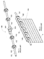
- Figs. 1 and 2 respectively show a device (100) according to the prior art used to wind and unwind rolling shutters, as well as a rolling shutter (5) fixed to said device (100).
- the device (100) comprises a fixed (not revolving) support bar (101).
- Two or more spring-holding boxes (102) with circular shape are mounted on the support bar (101), revolving idly.
- Each spring-holding box (102) contains a compensating spring (103) that is generally obtained with steel straps wound in spiral configuration.
- a first end of the compensating spring (103) is fixed to the support bar (101).
- a second end of the compensating spring (103) is fixed to the casing of the spring-holding boxes (102).
- a geared motor (104) is installed on the support bar (101).
- the geared motor (104) drives into rotation a pulley (140) that rotates around an axis coinciding with the longitudinal axis of the support bar (101).
- the pulley (140) has the same diameter as the spring-holding boxes (102).
- the rolling shutter (5) has an upper border (5a) fixed both to the pulley (140) and to the casing of the spring-holding boxes (102). Therefore, the spring-holding boxes (102) rotate around the support bar (101) when the geared motor (104) is actuated in order to wind or unwind the rolling shutter (5).
- the compensating springs (103) are unloaded when the shutter (5) is lifted and completely wound around the support bar (101), whereas the springs (103) are loaded with the maximum load when the shutter (5) is unwound completely, as shown in Fig. 2 .
- the compensating springs (103) are progressively loaded, taking advantage of the weight of the shutter (5), whereas, during the ascending travel of the shutter, the compensating springs (103) are unloaded, significantly contributing to the shutter lifting force exerted by the geared motor (104).
- the length and the diameter of the support bar (101), the number and the diameter of the spring-holding boxes (102), the length and the thickness of the steel straps used to make the spiral springs (103), the power of the geared motor (104), and the diameter of the pulley (140) vary according to the width and the weight of the shutter. Accordingly, in order to meet the diverse customer requirements, a rolling shutter manufacturer must store a large stock of different components in the warehouse.
- the assembly of the shutter is rather complicated.
- the assembly provides for mounting all spring-holding boxes (102) along the support bar (101), mounting the geared motor (4) on the support bar (101), and fixing the upper border (5a) of the shutter (5) to the pulley (140) and to the casing of all spring-holding boxes (102).
- CH688006 discloses an actuation device of rolling shutters that comprises a winding tube inside which a geared motor and a spiral spring are mounted.
- the shutter is fixed to the winding tube that is rotated by the electrical motor in order to wind the rolling shutter on the winding tube.
- Such a device is not versatile.
- the length of the winding tube must be the same as the width of the rolling shutter.
- the operator must stock a plurality of devices in the warehouse, with winding tubes of different length according to the width of the rolling shutters.
- DE4211940 discloses an actuation device for rolling shutters similar to CH688006 wherein a winding tube houses both a geared motor and a spiral spring. However, the device of DE4211940 is not provided with a system to adjust to the width of the rolling shutter or to the width of the window opening.
- CH206381 discloses a traditional rolling shutter winding device and a fixing system in order to adjust the device to small dimensional variations caused by defective fabrication.
- a fixing system provides for U-shaped brackets comprising two legs that are engaged with clearance in holes obtained in the masonry wall. The brackets are fixed to a flange connected to the winding device.
- Such a fixing system allows for vertical and horizontal adjustment of a few millimeters and is not capable of adjusting to the width of different rolling shutters that can differ in a few meters.
- the purpose of the present invention is to remedy the drawbacks of the prior art, by providing a supporting and motorized actuation device of rolling shutters, which is versatile and used for any width of the shutter or of the opening to be covered with the shutter.
- the first purpose of the invention is to provide a supporting and motorized actuation device of rolling shutters that allows a rolling shutter manufacturer to meet the most diverse requirements using the same standardized component, with consequent simplification and saving in terms of warehouse stock.
- An additional purpose of the invention is to provide a device that makes the installation of the shutter easier and safer.
- the device of the invention comprises a winding assembly, which is provided and pre-assembled both with a geared motor and a compensating spring assembly used to compensate the weight of the shutter.
- the winding assembly comprises a revolving casing with horizontal axis, and fast-coupling connectors disposed at the end of the winding assembly in order to couple two support bars.
- the revolving casing houses a support frame used to support a geared motor adapted to drive into rotation a pulley with horizontal axis, which is fixed to said revolving casing.
- the upper border of the shutter is fixed to the revolving casing and the shutter is supported and driven by said revolving casing, which also acts as winding drum for the entire shutter.
- the revolving casing also houses the compensating spring assembly, composed of helical torsional springs with ends joined to a fixed portion and to a revolving portion of the winding assembly, respectively.
- the compensating spring assembly is subject to a torsional stress and accumulates energy that, during the ascending travel of the shutter, contributes to the shutter lifting force exerted by the geared motor.
- the operator in charge of preparing and assembling the shutter simply needs to cut two identical bar sections to size and insert them from opposite sides in the fast-coupling connectors fixed to the winding assembly.
- the length of the bar sections must be identical to the total length of the shutter, after subtracting the length of the winding assembly that is disposed between the two bar sections.
- the helical springs of the compensating spring assembly are much safer than the spiral springs contained in the spring-holding boxes used in the prior art.
- the helical springs are contained and protected inside the revolving casing and are wound on the spring-holding sleeve that supports them.
- the device of the invention is disclosed, being generally indicated with reference numeral (200).
- the device (200) comprises a winding assembly (10).
- the winding assembly (10) comprises a revolving casing (70) whereon the upper border (5a) of a rolling shutter (5) is fixed, in such manner that the shutter (5) is wound onto the revolving casing (70) of the rolling assembly.
- the revolving casing (70) has a cylindrical shape.
- the winding assembly (10) comprises a geared motor (20) and a compensating spring assembly (30) disposed inside the revolving casing (70).
- the geared motor (20) is used to drive the revolving casing (70) into rotation.
- the compensating springs (30) are used to compensate the weight of the shutter (5).
- the winding assembly (10) comprises a support frame (T) used to support the geared motor (20) and the compensating spring assembly (30).
- the support frame (T) comprises a first support (40) that supports the motor (20) and a second support (50) that supports the compensating spring assembly (30).
- the two supports (40, 50) are shaped as a circular plate and disposed at the ends of the winding assembly (10).
- Two collars (80) are revolvingly mounted on the supports (40, 50) and fixed to the revolving casing (70). In view of the above the revolving casing (70) rotates with respect to the frame (T) that is fixed. Rolling bearings (90) are preferably interposed between the supports (40, 50) and the collars (80).
- the geared motor (20) has multiple reduction stages, for example of epicycloidal type.
- the geared motor (20) has a drive shaft (20a) connected to a pulley (21) disposed in a central portion of the winding assembly (10).
- the pulley (21) is fixed to the revolving casing (70) with fixing means (22), such as bolts. In this way the geared motor (20) drives the revolving casing (70) into rotation.
- the compensating spring assembly (30) comprises a first end (30b) fixed to the second support (50) of the frame and a second end (30a) connected to the pulley (21). In this way the compensating spring assembly (30) is loaded and unloaded according to the direction of rotation of the pulley (21).
- the compensating spring assembly (30) is connected to the pulley (21) by means of a disc-like coupling (71) fixed to the pulley (21).
- the compensating spring assembly (30) comprises helical torsional springs disposed coaxially one inside the other.
- the number of springs of the compensating spring assembly (30) changes according to the weight of the shutter (5).
- the concentric springs of the compensating spring assembly (30) are disposed on a spring-holding sleeve (74) fixed to the second support (50) of the frame.
- the second support (50) of the frame has a central hole (51) wherein the spring-holding sleeve (74) is fixed.
- the coupling (71) has a through central hole (72) that is crossed by one end of the spring-holding sleeve (74). Clearance is provided between the coupling (71) and the spring-holding sleeve (51) in order for the coupling (71) to rotate with respect to the spring-holding sleeve (74).
- the second support (50) and the coupling (71) have shanks (52, 73) that define housings adapted to contain the first end (30b) and the second end (30a) of the spring assembly, respectively.
- the coupling (71) drives the second end (30a) of the compensating spring assembly (30) into rotation around the axis (X), whereas the first end (30b) of the compensating spring assembly is kept fixed by the second support (50) of the frame.
- the device (10) of the invention comprises a pair of support bars (1) with tubular cylindrical shape.
- Each support bar (1) has a first ending section (13) and a second ending section (14).
- a first and a second fast-coupling connector (6) are fixed to the first support (40) and to the second support (50) of the frame, in such manner to axially protrude outwards in order to be coupled with the first ending section (13) of each support bar (1).
- a male-female coupling is provided between the first ending section (13) of the support bar (1) and the fast-coupling connector (6).
- each support bar is adapted to be fixed to a masonry wall.
- Each fast-coupling connector (6) comprises a flange (65) fixed to the support (40, 50) and a cylindrical shank (64) provided with a cylindrical housing (60) adapted to receive the ending section of the support bar (1).
- the shanks (64) of the fast-coupling connectors and the ending sections of the support bars (1) comprise radial holes (61, 15) adapted to receive stop plugs (62) to prevent the free removal of said support bars (1).
- the two support bars (1) are obtained from time to time by cutting two identical bar sections to size, starting from a long bar with standard length.
- a rolling shutter manufacturer can stock a suitable quantity of long bars with standard length in the warehouse. It must be noted that the length of the winding assembly (10) is considerably lower with respect to the width of the shutter (5) and consequently to the width of the opening that receives the shutter (5). The difference between the length of the winding assembly (10) and the width of the shutter (5) is compensated by the length of the support bars (1).
- the rolling shutter manufacturer can keep a stock of samples only for the two following standard components:
Landscapes
- Engineering & Computer Science (AREA)
- Structural Engineering (AREA)
- Architecture (AREA)
- Civil Engineering (AREA)
- Operating, Guiding And Securing Of Roll- Type Closing Members (AREA)
Priority Applications (2)
| Application Number | Priority Date | Filing Date | Title |
|---|---|---|---|
| ES14192522.2T ES2628146T3 (es) | 2014-11-10 | 2014-11-10 | Dispositivo de accionamiento motorizado y de soporte para persianas enrollables |
| EP14192522.2A EP3018283B1 (fr) | 2014-11-10 | 2014-11-10 | Support et dispositif d'actionnement motorisé de volets roulants |
Applications Claiming Priority (1)
| Application Number | Priority Date | Filing Date | Title |
|---|---|---|---|
| EP14192522.2A EP3018283B1 (fr) | 2014-11-10 | 2014-11-10 | Support et dispositif d'actionnement motorisé de volets roulants |
Publications (2)
| Publication Number | Publication Date |
|---|---|
| EP3018283A1 true EP3018283A1 (fr) | 2016-05-11 |
| EP3018283B1 EP3018283B1 (fr) | 2017-01-11 |
Family
ID=51947141
Family Applications (1)
| Application Number | Title | Priority Date | Filing Date |
|---|---|---|---|
| EP14192522.2A Active EP3018283B1 (fr) | 2014-11-10 | 2014-11-10 | Support et dispositif d'actionnement motorisé de volets roulants |
Country Status (2)
| Country | Link |
|---|---|
| EP (1) | EP3018283B1 (fr) |
| ES (1) | ES2628146T3 (fr) |
Cited By (2)
| Publication number | Priority date | Publication date | Assignee | Title |
|---|---|---|---|---|
| IT202200015963A1 (it) * | 2022-07-28 | 2024-01-28 | Davide Pederzini | Sistema per l'azionamento motorizzato di serrande avvolgibili a molle di compensazione e metodo di azionamento motorizzato di serrande avvolgibili a molle di compensazione con detto sistema. |
| US11905758B2 (en) | 2020-07-02 | 2024-02-20 | Springs Window Fashions, Llc | Roller shade assembly |
Citations (7)
| Publication number | Priority date | Publication date | Assignee | Title |
|---|---|---|---|---|
| CH206381A (de) | 1938-11-18 | 1939-08-15 | Metallbau A G | Vorrichtung zur Lagerung von Rolladen, insbesondere in Metallverschalungen. |
| DE1234970B (de) * | 1960-01-28 | 1967-02-23 | Karl Petzold | Lagerung der Welle eines Rolladens |
| DE4211940A1 (de) | 1992-04-09 | 1993-10-14 | Hermann Huss Rolladenbau Fa | Federwelle |
| CH688006A5 (fr) | 1995-10-30 | 1997-04-15 | Somfy | Dispositif de manoeuvre d'un élément de fermeture se déplacant au moins approximativement verticalement. |
| WO2008139526A1 (fr) * | 2007-04-27 | 2008-11-20 | Kunio Nasuno | Store vénitien ou volet à moteur d'entraînement d'ouverture/fermeture |
| US20130099714A1 (en) * | 2010-02-23 | 2013-04-25 | Homerun Holdings Corporation | High efficiency roller shade and method for setting artificial stops |
| US20130333848A1 (en) * | 2012-06-15 | 2013-12-19 | Homerun Holdings Corporation | Motorized roller shade configured for larger shade applications |
-
2014
- 2014-11-10 EP EP14192522.2A patent/EP3018283B1/fr active Active
- 2014-11-10 ES ES14192522.2T patent/ES2628146T3/es active Active
Patent Citations (7)
| Publication number | Priority date | Publication date | Assignee | Title |
|---|---|---|---|---|
| CH206381A (de) | 1938-11-18 | 1939-08-15 | Metallbau A G | Vorrichtung zur Lagerung von Rolladen, insbesondere in Metallverschalungen. |
| DE1234970B (de) * | 1960-01-28 | 1967-02-23 | Karl Petzold | Lagerung der Welle eines Rolladens |
| DE4211940A1 (de) | 1992-04-09 | 1993-10-14 | Hermann Huss Rolladenbau Fa | Federwelle |
| CH688006A5 (fr) | 1995-10-30 | 1997-04-15 | Somfy | Dispositif de manoeuvre d'un élément de fermeture se déplacant au moins approximativement verticalement. |
| WO2008139526A1 (fr) * | 2007-04-27 | 2008-11-20 | Kunio Nasuno | Store vénitien ou volet à moteur d'entraînement d'ouverture/fermeture |
| US20130099714A1 (en) * | 2010-02-23 | 2013-04-25 | Homerun Holdings Corporation | High efficiency roller shade and method for setting artificial stops |
| US20130333848A1 (en) * | 2012-06-15 | 2013-12-19 | Homerun Holdings Corporation | Motorized roller shade configured for larger shade applications |
Cited By (2)
| Publication number | Priority date | Publication date | Assignee | Title |
|---|---|---|---|---|
| US11905758B2 (en) | 2020-07-02 | 2024-02-20 | Springs Window Fashions, Llc | Roller shade assembly |
| IT202200015963A1 (it) * | 2022-07-28 | 2024-01-28 | Davide Pederzini | Sistema per l'azionamento motorizzato di serrande avvolgibili a molle di compensazione e metodo di azionamento motorizzato di serrande avvolgibili a molle di compensazione con detto sistema. |
Also Published As
| Publication number | Publication date |
|---|---|
| EP3018283B1 (fr) | 2017-01-11 |
| ES2628146T3 (es) | 2017-08-01 |
Similar Documents
| Publication | Publication Date | Title |
|---|---|---|
| US4882806A (en) | Counterbalancing torsion spring mechanism for devices which move up and down and method of setting the torsion springs thereof | |
| US8739854B2 (en) | Pre-assembled and pre-tensioned shade with indexing gear tensioner | |
| AU2016204677B2 (en) | Lifting apparatus for highly mounted equipment | |
| EP1577254B1 (fr) | Palan electrique | |
| KR101852036B1 (ko) | 롤러 셰이드용 파워 어시스트 모듈 | |
| DE69819670T2 (de) | Motorantrieb für tore | |
| US20140014281A1 (en) | Shade with a Shear Pin and Method for Pretensioning a Shade | |
| HK1209715A1 (en) | Spring-driven reel | |
| EP2122104B1 (fr) | Unité de moteur électrique tubulaire ajustable pour des éléments à enroulement tels que des stores et des articles similaires | |
| CN108691496A (zh) | 轴结构组件、锁闭或保护装置以及装配套件 | |
| AU2010200902B2 (en) | A roller door and a drive assembly for a roller door | |
| WO2017120658A1 (fr) | Dispositif de haubanage à câble métallique réglable en longueur et système de levage utilisant celui-ci | |
| EP3018283B1 (fr) | Support et dispositif d'actionnement motorisé de volets roulants | |
| DE102016114524B4 (de) | Trommelmotor mit Frequenzumrichter und optionalem Bandspannungssensor | |
| US8453707B2 (en) | Two-motor drive arrangement for a roller curtain | |
| US7296607B2 (en) | Side mount counterbalance system for upward acting door | |
| CN110869307A (zh) | 具有简化结构的绞盘 | |
| US6694673B2 (en) | Eccentrically mountable plug for counterbalancing systems of garage doors and the like | |
| US10641039B2 (en) | Cord separator for blind cord winding mechanism | |
| EP2828459B1 (fr) | Mécanisme de levage pour porte escamotable en plafond sectionnelle | |
| US20150013484A1 (en) | Device for Manually Actuating a Piece of Closing or Sun Protection Equipment | |
| CN211769544U (zh) | 一种线材收放卷装置 | |
| EP2960197B1 (fr) | Enroulement de secours pour systèmes électriques de protection contre le soleil et l'éblouissement | |
| KR20230161600A (ko) | 승강기구 | |
| CN220015012U (zh) | 一种卷帘装置 |
Legal Events
| Date | Code | Title | Description |
|---|---|---|---|
| PUAI | Public reference made under article 153(3) epc to a published international application that has entered the european phase |
Free format text: ORIGINAL CODE: 0009012 |
|
| 17P | Request for examination filed |
Effective date: 20151105 |
|
| AK | Designated contracting states |
Kind code of ref document: A1 Designated state(s): AL AT BE BG CH CY CZ DE DK EE ES FI FR GB GR HR HU IE IS IT LI LT LU LV MC MK MT NL NO PL PT RO RS SE SI SK SM TR |
|
| AX | Request for extension of the european patent |
Extension state: BA ME |
|
| REG | Reference to a national code |
Ref country code: DE Ref legal event code: R079 Ref document number: 602014006175 Country of ref document: DE Free format text: PREVIOUS MAIN CLASS: E06B0009600000 Ipc: E06B0009150000 |
|
| RIC1 | Information provided on ipc code assigned before grant |
Ipc: E06B 9/62 20060101ALI20160517BHEP Ipc: E06B 9/72 20060101ALI20160517BHEP Ipc: E06B 9/60 20060101ALI20160517BHEP Ipc: E06B 9/15 20060101AFI20160517BHEP Ipc: E06B 9/171 20060101ALI20160517BHEP |
|
| GRAP | Despatch of communication of intention to grant a patent |
Free format text: ORIGINAL CODE: EPIDOSNIGR1 |
|
| INTG | Intention to grant announced |
Effective date: 20160630 |
|
| RAP1 | Party data changed (applicant data changed or rights of an application transferred) |
Owner name: POSTACCHINI, ROBERTO Owner name: POSTACCHINI, DANTE |
|
| RIN1 | Information on inventor provided before grant (corrected) |
Inventor name: POSTACCHINI, ROBERTO Inventor name: POSTACCHINI, DANTE |
|
| GRAS | Grant fee paid |
Free format text: ORIGINAL CODE: EPIDOSNIGR3 |
|
| GRAA | (expected) grant |
Free format text: ORIGINAL CODE: 0009210 |
|
| AK | Designated contracting states |
Kind code of ref document: B1 Designated state(s): AL AT BE BG CH CY CZ DE DK EE ES FI FR GB GR HR HU IE IS IT LI LT LU LV MC MK MT NL NO PL PT RO RS SE SI SK SM TR |
|
| REG | Reference to a national code |
Ref country code: GB Ref legal event code: FG4D |
|
| REG | Reference to a national code |
Ref country code: CH Ref legal event code: EP |
|
| REG | Reference to a national code |
Ref country code: AT Ref legal event code: REF Ref document number: 861475 Country of ref document: AT Kind code of ref document: T Effective date: 20170115 |
|
| REG | Reference to a national code |
Ref country code: IE Ref legal event code: FG4D |
|
| REG | Reference to a national code |
Ref country code: DE Ref legal event code: R096 Ref document number: 602014006175 Country of ref document: DE |
|
| REG | Reference to a national code |
Ref country code: LT Ref legal event code: MG4D |
|
| REG | Reference to a national code |
Ref country code: NL Ref legal event code: MP Effective date: 20170111 |
|
| REG | Reference to a national code |
Ref country code: AT Ref legal event code: MK05 Ref document number: 861475 Country of ref document: AT Kind code of ref document: T Effective date: 20170111 |
|
| PG25 | Lapsed in a contracting state [announced via postgrant information from national office to epo] |
Ref country code: NL Free format text: LAPSE BECAUSE OF FAILURE TO SUBMIT A TRANSLATION OF THE DESCRIPTION OR TO PAY THE FEE WITHIN THE PRESCRIBED TIME-LIMIT Effective date: 20170111 |
|
| PG25 | Lapsed in a contracting state [announced via postgrant information from national office to epo] |
Ref country code: LT Free format text: LAPSE BECAUSE OF FAILURE TO SUBMIT A TRANSLATION OF THE DESCRIPTION OR TO PAY THE FEE WITHIN THE PRESCRIBED TIME-LIMIT Effective date: 20170111 Ref country code: NO Free format text: LAPSE BECAUSE OF FAILURE TO SUBMIT A TRANSLATION OF THE DESCRIPTION OR TO PAY THE FEE WITHIN THE PRESCRIBED TIME-LIMIT Effective date: 20170411 Ref country code: HR Free format text: LAPSE BECAUSE OF FAILURE TO SUBMIT A TRANSLATION OF THE DESCRIPTION OR TO PAY THE FEE WITHIN THE PRESCRIBED TIME-LIMIT Effective date: 20170111 Ref country code: FI Free format text: LAPSE BECAUSE OF FAILURE TO SUBMIT A TRANSLATION OF THE DESCRIPTION OR TO PAY THE FEE WITHIN THE PRESCRIBED TIME-LIMIT Effective date: 20170111 Ref country code: IS Free format text: LAPSE BECAUSE OF FAILURE TO SUBMIT A TRANSLATION OF THE DESCRIPTION OR TO PAY THE FEE WITHIN THE PRESCRIBED TIME-LIMIT Effective date: 20170511 Ref country code: GR Free format text: LAPSE BECAUSE OF FAILURE TO SUBMIT A TRANSLATION OF THE DESCRIPTION OR TO PAY THE FEE WITHIN THE PRESCRIBED TIME-LIMIT Effective date: 20170412 |
|
| REG | Reference to a national code |
Ref country code: ES Ref legal event code: FG2A Ref document number: 2628146 Country of ref document: ES Kind code of ref document: T3 Effective date: 20170801 |
|
| PG25 | Lapsed in a contracting state [announced via postgrant information from national office to epo] |
Ref country code: PT Free format text: LAPSE BECAUSE OF FAILURE TO SUBMIT A TRANSLATION OF THE DESCRIPTION OR TO PAY THE FEE WITHIN THE PRESCRIBED TIME-LIMIT Effective date: 20170511 Ref country code: PL Free format text: LAPSE BECAUSE OF FAILURE TO SUBMIT A TRANSLATION OF THE DESCRIPTION OR TO PAY THE FEE WITHIN THE PRESCRIBED TIME-LIMIT Effective date: 20170111 Ref country code: SE Free format text: LAPSE BECAUSE OF FAILURE TO SUBMIT A TRANSLATION OF THE DESCRIPTION OR TO PAY THE FEE WITHIN THE PRESCRIBED TIME-LIMIT Effective date: 20170111 Ref country code: RS Free format text: LAPSE BECAUSE OF FAILURE TO SUBMIT A TRANSLATION OF THE DESCRIPTION OR TO PAY THE FEE WITHIN THE PRESCRIBED TIME-LIMIT Effective date: 20170111 Ref country code: AT Free format text: LAPSE BECAUSE OF FAILURE TO SUBMIT A TRANSLATION OF THE DESCRIPTION OR TO PAY THE FEE WITHIN THE PRESCRIBED TIME-LIMIT Effective date: 20170111 Ref country code: LV Free format text: LAPSE BECAUSE OF FAILURE TO SUBMIT A TRANSLATION OF THE DESCRIPTION OR TO PAY THE FEE WITHIN THE PRESCRIBED TIME-LIMIT Effective date: 20170111 Ref country code: BG Free format text: LAPSE BECAUSE OF FAILURE TO SUBMIT A TRANSLATION OF THE DESCRIPTION OR TO PAY THE FEE WITHIN THE PRESCRIBED TIME-LIMIT Effective date: 20170411 |
|
| REG | Reference to a national code |
Ref country code: FR Ref legal event code: PLFP Year of fee payment: 4 |
|
| REG | Reference to a national code |
Ref country code: DE Ref legal event code: R097 Ref document number: 602014006175 Country of ref document: DE |
|
| PG25 | Lapsed in a contracting state [announced via postgrant information from national office to epo] |
Ref country code: RO Free format text: LAPSE BECAUSE OF FAILURE TO SUBMIT A TRANSLATION OF THE DESCRIPTION OR TO PAY THE FEE WITHIN THE PRESCRIBED TIME-LIMIT Effective date: 20170111 Ref country code: CZ Free format text: LAPSE BECAUSE OF FAILURE TO SUBMIT A TRANSLATION OF THE DESCRIPTION OR TO PAY THE FEE WITHIN THE PRESCRIBED TIME-LIMIT Effective date: 20170111 Ref country code: EE Free format text: LAPSE BECAUSE OF FAILURE TO SUBMIT A TRANSLATION OF THE DESCRIPTION OR TO PAY THE FEE WITHIN THE PRESCRIBED TIME-LIMIT Effective date: 20170111 Ref country code: SK Free format text: LAPSE BECAUSE OF FAILURE TO SUBMIT A TRANSLATION OF THE DESCRIPTION OR TO PAY THE FEE WITHIN THE PRESCRIBED TIME-LIMIT Effective date: 20170111 |
|
| PLBE | No opposition filed within time limit |
Free format text: ORIGINAL CODE: 0009261 |
|
| STAA | Information on the status of an ep patent application or granted ep patent |
Free format text: STATUS: NO OPPOSITION FILED WITHIN TIME LIMIT |
|
| PG25 | Lapsed in a contracting state [announced via postgrant information from national office to epo] |
Ref country code: SM Free format text: LAPSE BECAUSE OF FAILURE TO SUBMIT A TRANSLATION OF THE DESCRIPTION OR TO PAY THE FEE WITHIN THE PRESCRIBED TIME-LIMIT Effective date: 20170111 Ref country code: DK Free format text: LAPSE BECAUSE OF FAILURE TO SUBMIT A TRANSLATION OF THE DESCRIPTION OR TO PAY THE FEE WITHIN THE PRESCRIBED TIME-LIMIT Effective date: 20170111 |
|
| 26N | No opposition filed |
Effective date: 20171012 |
|
| PG25 | Lapsed in a contracting state [announced via postgrant information from national office to epo] |
Ref country code: SI Free format text: LAPSE BECAUSE OF FAILURE TO SUBMIT A TRANSLATION OF THE DESCRIPTION OR TO PAY THE FEE WITHIN THE PRESCRIBED TIME-LIMIT Effective date: 20170111 |
|
| PGFP | Annual fee paid to national office [announced via postgrant information from national office to epo] |
Ref country code: BE Payment date: 20171024 Year of fee payment: 4 Ref country code: CH Payment date: 20171115 Year of fee payment: 4 |
|
| PG25 | Lapsed in a contracting state [announced via postgrant information from national office to epo] |
Ref country code: MC Free format text: LAPSE BECAUSE OF FAILURE TO SUBMIT A TRANSLATION OF THE DESCRIPTION OR TO PAY THE FEE WITHIN THE PRESCRIBED TIME-LIMIT Effective date: 20170111 |
|
| PG25 | Lapsed in a contracting state [announced via postgrant information from national office to epo] |
Ref country code: LU Free format text: LAPSE BECAUSE OF NON-PAYMENT OF DUE FEES Effective date: 20171110 |
|
| PG25 | Lapsed in a contracting state [announced via postgrant information from national office to epo] |
Ref country code: MT Free format text: LAPSE BECAUSE OF NON-PAYMENT OF DUE FEES Effective date: 20171110 |
|
| REG | Reference to a national code |
Ref country code: ES Ref legal event code: PC2A Owner name: MOVEUP, S.R.L. Effective date: 20181106 |
|
| REG | Reference to a national code |
Ref country code: GB Ref legal event code: 732E Free format text: REGISTERED BETWEEN 20181025 AND 20181102 |
|
| REG | Reference to a national code |
Ref country code: DE Ref legal event code: R081 Ref document number: 602014006175 Country of ref document: DE Owner name: MOVEUP S.R.L., IT Free format text: FORMER OWNERS: POSTACCHINI, DANTE, FERMO, IT; POSTACCHINI, ROBERTO, FERMO, IT |
|
| PG25 | Lapsed in a contracting state [announced via postgrant information from national office to epo] |
Ref country code: HU Free format text: LAPSE BECAUSE OF FAILURE TO SUBMIT A TRANSLATION OF THE DESCRIPTION OR TO PAY THE FEE WITHIN THE PRESCRIBED TIME-LIMIT; INVALID AB INITIO Effective date: 20141110 |
|
| REG | Reference to a national code |
Ref country code: CH Ref legal event code: PL |
|
| REG | Reference to a national code |
Ref country code: BE Ref legal event code: MM Effective date: 20181130 |
|
| PG25 | Lapsed in a contracting state [announced via postgrant information from national office to epo] |
Ref country code: CH Free format text: LAPSE BECAUSE OF NON-PAYMENT OF DUE FEES Effective date: 20181130 Ref country code: LI Free format text: LAPSE BECAUSE OF NON-PAYMENT OF DUE FEES Effective date: 20181130 |
|
| PG25 | Lapsed in a contracting state [announced via postgrant information from national office to epo] |
Ref country code: CY Free format text: LAPSE BECAUSE OF FAILURE TO SUBMIT A TRANSLATION OF THE DESCRIPTION OR TO PAY THE FEE WITHIN THE PRESCRIBED TIME-LIMIT Effective date: 20170111 |
|
| PG25 | Lapsed in a contracting state [announced via postgrant information from national office to epo] |
Ref country code: MK Free format text: LAPSE BECAUSE OF FAILURE TO SUBMIT A TRANSLATION OF THE DESCRIPTION OR TO PAY THE FEE WITHIN THE PRESCRIBED TIME-LIMIT Effective date: 20170111 Ref country code: BE Free format text: LAPSE BECAUSE OF NON-PAYMENT OF DUE FEES Effective date: 20181130 |
|
| PG25 | Lapsed in a contracting state [announced via postgrant information from national office to epo] |
Ref country code: TR Free format text: LAPSE BECAUSE OF FAILURE TO SUBMIT A TRANSLATION OF THE DESCRIPTION OR TO PAY THE FEE WITHIN THE PRESCRIBED TIME-LIMIT Effective date: 20170111 |
|
| PG25 | Lapsed in a contracting state [announced via postgrant information from national office to epo] |
Ref country code: AL Free format text: LAPSE BECAUSE OF FAILURE TO SUBMIT A TRANSLATION OF THE DESCRIPTION OR TO PAY THE FEE WITHIN THE PRESCRIBED TIME-LIMIT Effective date: 20170111 |
|
| PGFP | Annual fee paid to national office [announced via postgrant information from national office to epo] |
Ref country code: GB Payment date: 20211123 Year of fee payment: 8 Ref country code: IE Payment date: 20211118 Year of fee payment: 8 |
|
| P01 | Opt-out of the competence of the unified patent court (upc) registered |
Effective date: 20230515 |
|
| GBPC | Gb: european patent ceased through non-payment of renewal fee |
Effective date: 20221110 |
|
| PG25 | Lapsed in a contracting state [announced via postgrant information from national office to epo] |
Ref country code: IE Free format text: LAPSE BECAUSE OF NON-PAYMENT OF DUE FEES Effective date: 20221110 Ref country code: GB Free format text: LAPSE BECAUSE OF NON-PAYMENT OF DUE FEES Effective date: 20221110 |
|
| PGFP | Annual fee paid to national office [announced via postgrant information from national office to epo] |
Ref country code: DE Payment date: 20241128 Year of fee payment: 11 |
|
| PGFP | Annual fee paid to national office [announced via postgrant information from national office to epo] |
Ref country code: IT Payment date: 20251021 Year of fee payment: 12 |
|
| PGFP | Annual fee paid to national office [announced via postgrant information from national office to epo] |
Ref country code: FR Payment date: 20251124 Year of fee payment: 12 |
|
| PGFP | Annual fee paid to national office [announced via postgrant information from national office to epo] |
Ref country code: ES Payment date: 20251209 Year of fee payment: 12 |