EP3018288A1 - Hochdruckkompressorrotorwärmekonditionierung mittels ausströmdruckluft - Google Patents
Hochdruckkompressorrotorwärmekonditionierung mittels ausströmdruckluft Download PDFInfo
- Publication number
- EP3018288A1 EP3018288A1 EP15192939.5A EP15192939A EP3018288A1 EP 3018288 A1 EP3018288 A1 EP 3018288A1 EP 15192939 A EP15192939 A EP 15192939A EP 3018288 A1 EP3018288 A1 EP 3018288A1
- Authority
- EP
- European Patent Office
- Prior art keywords
- disc
- compressor
- valve
- bore
- path
- Prior art date
- Legal status (The legal status is an assumption and is not a legal conclusion. Google has not performed a legal analysis and makes no representation as to the accuracy of the status listed.)
- Granted
Links
Images



Classifications
-
- F—MECHANICAL ENGINEERING; LIGHTING; HEATING; WEAPONS; BLASTING
- F02—COMBUSTION ENGINES; HOT-GAS OR COMBUSTION-PRODUCT ENGINE PLANTS
- F02C—GAS-TURBINE PLANTS; AIR INTAKES FOR JET-PROPULSION PLANTS; CONTROLLING FUEL SUPPLY IN AIR-BREATHING JET-PROPULSION PLANTS
- F02C9/00—Controlling gas-turbine plants; Controlling fuel supply in air- breathing jet-propulsion plants
- F02C9/16—Control of working fluid flow
- F02C9/18—Control of working fluid flow by bleeding, bypassing or acting on variable working fluid interconnections between turbines or compressors or their stages
-
- F—MECHANICAL ENGINEERING; LIGHTING; HEATING; WEAPONS; BLASTING
- F01—MACHINES OR ENGINES IN GENERAL; ENGINE PLANTS IN GENERAL; STEAM ENGINES
- F01D—NON-POSITIVE DISPLACEMENT MACHINES OR ENGINES, e.g. STEAM TURBINES
- F01D19/00—Starting of machines or engines; Regulating, controlling, or safety means in connection therewith
- F01D19/02—Starting of machines or engines; Regulating, controlling, or safety means in connection therewith dependent on temperature of component parts, e.g. of turbine-casing
-
- F—MECHANICAL ENGINEERING; LIGHTING; HEATING; WEAPONS; BLASTING
- F01—MACHINES OR ENGINES IN GENERAL; ENGINE PLANTS IN GENERAL; STEAM ENGINES
- F01D—NON-POSITIVE DISPLACEMENT MACHINES OR ENGINES, e.g. STEAM TURBINES
- F01D5/00—Blades; Blade-carrying members; Heating, heat-insulating, cooling or antivibration means on the blades or the members
- F01D5/02—Blade-carrying members, e.g. rotors
- F01D5/08—Heating, heat-insulating or cooling means
- F01D5/085—Heating, heat-insulating or cooling means cooling fluid circulating inside the rotor
- F01D5/087—Heating, heat-insulating or cooling means cooling fluid circulating inside the rotor in the radial passages of the rotor disc
-
- F—MECHANICAL ENGINEERING; LIGHTING; HEATING; WEAPONS; BLASTING
- F02—COMBUSTION ENGINES; HOT-GAS OR COMBUSTION-PRODUCT ENGINE PLANTS
- F02C—GAS-TURBINE PLANTS; AIR INTAKES FOR JET-PROPULSION PLANTS; CONTROLLING FUEL SUPPLY IN AIR-BREATHING JET-PROPULSION PLANTS
- F02C3/00—Gas-turbine plants characterised by the use of combustion products as the working fluid
- F02C3/04—Gas-turbine plants characterised by the use of combustion products as the working fluid having a turbine driving a compressor
-
- F—MECHANICAL ENGINEERING; LIGHTING; HEATING; WEAPONS; BLASTING
- F02—COMBUSTION ENGINES; HOT-GAS OR COMBUSTION-PRODUCT ENGINE PLANTS
- F02C—GAS-TURBINE PLANTS; AIR INTAKES FOR JET-PROPULSION PLANTS; CONTROLLING FUEL SUPPLY IN AIR-BREATHING JET-PROPULSION PLANTS
- F02C6/00—Plural gas-turbine plants; Combinations of gas-turbine plants with other apparatus; Adaptations of gas-turbine plants for special use
- F02C6/04—Gas-turbine plants providing heated or pressurised working fluid for other apparatus, e.g. without mechanical power output
- F02C6/06—Gas-turbine plants providing heated or pressurised working fluid for other apparatus, e.g. without mechanical power output providing compressed gas
- F02C6/08—Gas-turbine plants providing heated or pressurised working fluid for other apparatus, e.g. without mechanical power output providing compressed gas the gas being bled from the gas-turbine compressor
-
- F—MECHANICAL ENGINEERING; LIGHTING; HEATING; WEAPONS; BLASTING
- F02—COMBUSTION ENGINES; HOT-GAS OR COMBUSTION-PRODUCT ENGINE PLANTS
- F02C—GAS-TURBINE PLANTS; AIR INTAKES FOR JET-PROPULSION PLANTS; CONTROLLING FUEL SUPPLY IN AIR-BREATHING JET-PROPULSION PLANTS
- F02C7/00—Features, components parts, details or accessories, not provided for in, or of interest apart form groups F02C1/00 - F02C6/00; Air intakes for jet-propulsion plants
- F02C7/12—Cooling of plants
- F02C7/16—Cooling of plants characterised by cooling medium
- F02C7/18—Cooling of plants characterised by cooling medium the medium being gaseous, e.g. air
- F02C7/185—Cooling means for reducing the temperature of the cooling air or gas
-
- F—MECHANICAL ENGINEERING; LIGHTING; HEATING; WEAPONS; BLASTING
- F04—POSITIVE - DISPLACEMENT MACHINES FOR LIQUIDS; PUMPS FOR LIQUIDS OR ELASTIC FLUIDS
- F04D—NON-POSITIVE-DISPLACEMENT PUMPS
- F04D29/00—Details, component parts, or accessories
- F04D29/26—Rotors specially for elastic fluids
- F04D29/32—Rotors specially for elastic fluids for axial flow pumps
- F04D29/321—Rotors specially for elastic fluids for axial flow pumps for axial flow compressors
- F04D29/324—Blades
-
- F—MECHANICAL ENGINEERING; LIGHTING; HEATING; WEAPONS; BLASTING
- F05—INDEXING SCHEMES RELATING TO ENGINES OR PUMPS IN VARIOUS SUBCLASSES OF CLASSES F01-F04
- F05D—INDEXING SCHEME FOR ASPECTS RELATING TO NON-POSITIVE-DISPLACEMENT MACHINES OR ENGINES, GAS-TURBINES OR JET-PROPULSION PLANTS
- F05D2220/00—Application
- F05D2220/30—Application in turbines
- F05D2220/32—Application in turbines in gas turbines
-
- F—MECHANICAL ENGINEERING; LIGHTING; HEATING; WEAPONS; BLASTING
- F05—INDEXING SCHEMES RELATING TO ENGINES OR PUMPS IN VARIOUS SUBCLASSES OF CLASSES F01-F04
- F05D—INDEXING SCHEME FOR ASPECTS RELATING TO NON-POSITIVE-DISPLACEMENT MACHINES OR ENGINES, GAS-TURBINES OR JET-PROPULSION PLANTS
- F05D2220/00—Application
- F05D2220/30—Application in turbines
- F05D2220/32—Application in turbines in gas turbines
- F05D2220/323—Application in turbines in gas turbines for aircraft propulsion, e.g. jet engines
-
- F—MECHANICAL ENGINEERING; LIGHTING; HEATING; WEAPONS; BLASTING
- F05—INDEXING SCHEMES RELATING TO ENGINES OR PUMPS IN VARIOUS SUBCLASSES OF CLASSES F01-F04
- F05D—INDEXING SCHEME FOR ASPECTS RELATING TO NON-POSITIVE-DISPLACEMENT MACHINES OR ENGINES, GAS-TURBINES OR JET-PROPULSION PLANTS
- F05D2240/00—Components
- F05D2240/20—Rotors
-
- F—MECHANICAL ENGINEERING; LIGHTING; HEATING; WEAPONS; BLASTING
- F05—INDEXING SCHEMES RELATING TO ENGINES OR PUMPS IN VARIOUS SUBCLASSES OF CLASSES F01-F04
- F05D—INDEXING SCHEME FOR ASPECTS RELATING TO NON-POSITIVE-DISPLACEMENT MACHINES OR ENGINES, GAS-TURBINES OR JET-PROPULSION PLANTS
- F05D2240/00—Components
- F05D2240/35—Combustors or associated equipment
-
- F—MECHANICAL ENGINEERING; LIGHTING; HEATING; WEAPONS; BLASTING
- F05—INDEXING SCHEMES RELATING TO ENGINES OR PUMPS IN VARIOUS SUBCLASSES OF CLASSES F01-F04
- F05D—INDEXING SCHEME FOR ASPECTS RELATING TO NON-POSITIVE-DISPLACEMENT MACHINES OR ENGINES, GAS-TURBINES OR JET-PROPULSION PLANTS
- F05D2260/00—Function
- F05D2260/20—Heat transfer, e.g. cooling
- F05D2260/213—Heat transfer, e.g. cooling by the provision of a heat exchanger within the cooling circuit
-
- F—MECHANICAL ENGINEERING; LIGHTING; HEATING; WEAPONS; BLASTING
- F05—INDEXING SCHEMES RELATING TO ENGINES OR PUMPS IN VARIOUS SUBCLASSES OF CLASSES F01-F04
- F05D—INDEXING SCHEME FOR ASPECTS RELATING TO NON-POSITIVE-DISPLACEMENT MACHINES OR ENGINES, GAS-TURBINES OR JET-PROPULSION PLANTS
- F05D2270/00—Control
- F05D2270/01—Purpose of the control system
- F05D2270/11—Purpose of the control system to prolong engine life
- F05D2270/114—Purpose of the control system to prolong engine life by limiting mechanical stresses
-
- Y—GENERAL TAGGING OF NEW TECHNOLOGICAL DEVELOPMENTS; GENERAL TAGGING OF CROSS-SECTIONAL TECHNOLOGIES SPANNING OVER SEVERAL SECTIONS OF THE IPC; TECHNICAL SUBJECTS COVERED BY FORMER USPC CROSS-REFERENCE ART COLLECTIONS [XRACs] AND DIGESTS
- Y02—TECHNOLOGIES OR APPLICATIONS FOR MITIGATION OR ADAPTATION AGAINST CLIMATE CHANGE
- Y02T—CLIMATE CHANGE MITIGATION TECHNOLOGIES RELATED TO TRANSPORTATION
- Y02T50/00—Aeronautics or air transport
- Y02T50/60—Efficient propulsion technologies, e.g. for aircraft
Definitions
- This application relates to extracting compressed air for thermal conditioning of a high pressure compressor rotor.
- Gas turbine engines used on aircraft typically include a fan delivering air into a bypass duct and into a compressor section. Air from the compressor is passed downstream into a combustion section where it is mixed with fuel and ignited. Products of this combustion pass downstream over turbine rotors driving them to rotate.
- Turbine rotors drive compressor and fan rotors.
- the fan rotor was driven at the same speed as a turbine rotor.
- the diameter of the fan has increased dramatically and a bypass ratio or volume of air delivered into the bypass duct compared to a volume delivered into the compressor has increased. With this increase in bypass ratio, it becomes more important to efficiently utilize the air that is delivered into the compressor.
- T 3 The temperature at the exit of the high pressure compressor.
- Thermal gradient challenges are greatest during large changes in power setting. For instance, when an associated aircraft moves from idle to take-off, or cruise to decent. It is possible that the thermal stress in the disk is much greater than the stress due to the centrifugal force on the disk. The engine has typically been at low speed or idle as the aircraft waits on the ground and then, just before take-off, the speed of the engine is increased dramatically. Disk thermal gradient stresses may result in a compressor design that cannot achieve desired pressures.
- a compressor for use in a gas turbine engine comprises a compressor rotor including blades and a disc, with a bore defined radially inwardly of the disc.
- a high pressure air tap includes a lower temperature tapped path and a higher temperature tapped path and a valve for selectively delivering one of the lower temperature tapped path and the higher temperature tapped path into the bore of the disc.
- the valve is operable to selectively block flow of either of the lower pressure and higher pressure tapped paths to the bore of the disc, with the disc including holes to allow air from compressor chambers to communicate with the bore of the disc.
- the lower temperature tapped path passes through a heat exchanger before reaching the valve.
- valve allows flow from the higher temperature tapped path when the associated engine is moving from a lower power operation to a higher power operation.
- the valve delivers the lower temperature tapped path to the bore of the disc when the engine is at higher power operation.
- valve blocks flow of both the higher pressure and lower pressure tapped paths when the engine is operating at other lower power settings.
- air from the compressor chamber passes radially inwardly through the holes in the disc, and into the bore of the disc when the valve blocks flow of both the higher pressure and lower pressure paths.
- valve communicates the higher temperature tap path radially inwardly of the blades, through the disc, and into the bore when the engine is operating at other lower power settings.
- a seal blocks flow of air at a radially inner portion of the compressor section from passing upstream.
- a gas turbine engine comprises a compressor section, a combustor, and a turbine section.
- the compressor section includes a compressor rotor including blades and a disc, with a bore defined radially inwardly of the disc.
- a high pressure air tap includes a lower temperature tapped path and a higher temperature tapped path and a valve for selectively delivering one of the lower temperature tapped path and the higher temperature tapped path into the bore of the disc.
- the valve is operable to selectively block flow of either of the lower pressure and higher pressure tapped paths to the bore of the disc, with the disc including holes to allow air from compressor chambers to communicate with the bore of the disc.
- the lower temperature tapped path passes through a heat exchanger before reaching the valve.
- valve allows flow from the higher temperature tapped path when the associated engine is moving from a lower power operation to a higher power operation.
- the valve delivers the lower temperature tapped path to the bore of the disc when the engine is at higher power operation.
- valve blocks flow of both the higher pressure and lower pressure tapped paths when the engine is operating at other lower power settings.
- air from the compressor chamber passes radially inwardly through the holes in the disc, and into the bore of the disc when the valve blocks flow of both the higher pressure and lower pressure paths.
- valve communicates the higher temperature tap path radially inwardly of the blades, through the disc, and into the bore when the engine is operating at other lower power settings.
- a seal blocks flow of air at a radially inner portion of the compressor section from passing upstream.
- a method of operating a gas turbine engine includes the steps of tapping air from a compressor section exit, the compressor section having a rotor including blades and a disc, with a bore defined radially inwardly of the disc.
- the high pressure air tap includes a lower temperature tapped path and a higher temperature tapped path and a valve selectively delivering one of the lower temperature tapped path and the higher temperature tapped path into the bore of the disc.
- the valve selectively blocks flow of either, or both, of the lower pressure and higher pressure tapped paths to the bore of the disc.
- the lower temperature tapped path passes through a heat exchanger before reaching the valve.
- air from the compressor chamber passes radially inwardly through holes in the disc, and into the bore of the disc when the valve blocks flow of both the higher pressure and lower pressure paths.
- the valve communicates the higher temperature tap path radially inwardly of the blades, through the disc, and into the bore when the engine is operating at some lower power settings.
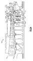
- FIG. 1 schematically illustrates a gas turbine engine 20.
- the gas turbine engine 20 is disclosed herein as a two-spool turbofan that generally incorporates a fan section 22, a compressor section 24, a combustor section 26 and a turbine section 28.
- Alternative engines might include an augmentor section (not shown) among other systems or features.
- the fan section 22 drives air along a bypass flow path B in a bypass duct defined within a nacelle 15, while the compressor section 24 drives air along a core flow path C for compression and communication into the combustor section 26 then expansion through the turbine section 28.
- the exemplary engine 20 generally includes a low speed spool 30 and a high speed spool 32 mounted for rotation about an engine central longitudinal axis A relative to an engine static structure 36 via several bearing systems 38. It should be understood that various bearing systems 38 at various locations may alternatively or additionally be provided, and the location of bearing systems 38 may be varied as appropriate to the application.
- the low speed spool 30 generally includes an inner shaft 40 that interconnects a fan 42, a first (or low) pressure compressor 44 and a first (or low) pressure turbine 46.
- the inner shaft 40 is connected to the fan 42 through a speed change mechanism, which in exemplary gas turbine engine 20 is illustrated as a geared architecture 48 to drive the fan 42 at a lower speed than the low speed spool 30.
- the high speed spool 32 includes an outer shaft 50 that interconnects a second (or high) pressure compressor 52 and a second (or high) pressure turbine 54.
- a combustor 56 is arranged in exemplary gas turbine 20 between the high pressure compressor 52 and the high pressure turbine 54.
- a mid-turbine frame 57 of the engine static structure 36 is arranged generally between the high pressure turbine 54 and the low pressure turbine 46.
- the mid-turbine frame 57 further supports bearing systems 38 in the turbine section 28.
- the inner shaft 40 and the outer shaft 50 are concentric and rotate via bearing systems 38 about the engine central longitudinal axis A which is collinear with their longitudinal axes.
- the core airflow is compressed by the low pressure compressor 44 then the high pressure compressor 52, mixed and burned with fuel in the combustor 56, then expanded over the high pressure turbine 54 and low pressure turbine 46.
- the mid-turbine frame 57 includes airfoils 59 which are in the core airflow path C.
- the turbines 46, 54 rotationally drive the respective low speed spool 30 and high speed spool 32 in response to the expansion.
- gear system 48 may be located aft of combustor section 26 or even aft of turbine section 28, and fan section 22 may be positioned forward or aft of the location of gear system 48.
- the engine 20 in one example is a high-bypass geared aircraft engine.
- the engine 20 bypass ratio is greater than about six (6), with an example embodiment being greater than about ten (10)
- the geared architecture 48 is an epicyclic gear train, such as a planetary gear system or other gear system, with a gear reduction ratio of greater than about 2.3
- the low pressure turbine 46 has a pressure ratio that is greater than about five.
- the engine 20 bypass ratio is greater than about ten (10:1)
- the fan diameter is significantly larger than that of the low pressure compressor 44
- the low pressure turbine 46 has a pressure ratio that is greater than about five 5:1.
- Low pressure turbine 46 pressure ratio is pressure measured prior to inlet of low pressure turbine 46 as related to the pressure at the outlet of the low pressure turbine 46 prior to an exhaust nozzle.
- the geared architecture 48 may be an epicycle gear train, such as a planetary gear system or other gear system, with a gear reduction ratio of greater than about 2.3:1. It should be understood, however, that the above parameters are only exemplary of one embodiment of a geared architecture engine and that the present invention is applicable to other gas turbine engines including direct drive turbofans.
- the fan section 22 of the engine 20 is designed for a particular flight condition -- typically cruise at about 0.8 Mach and about 35,000 feet (10,668 meters).
- the flight condition of 0.8 Mach and 35,000 ft (10,668 meters), with the engine at its best fuel consumption - also known as "bucket cruise Thrust Specific Fuel Consumption ('TSFC')" - is the industry standard parameter of lbm of fuel being burned divided by lbf of thrust the engine produces at that minimum point.
- "Low fan pressure ratio” is the pressure ratio across the fan blade alone, without a Fan Exit Guide Vane (“FEGV”) system.
- the low fan pressure ratio as disclosed herein according to one non-limiting embodiment is less than about 1.45.
- Low corrected fan tip speed is the actual fan tip speed in ft/sec divided by an industry standard temperature correction of [(Tram °R) / (518.7 °R)] 0.5 .
- the "Low corrected fan tip speed” as disclosed herein according to one non-limiting embodiment is less than about 1150 ft / second (350.5 meters/second).
- FIG. 2A shows a high pressure compressor section 100. While a number of stages are illustrated, this disclosure focuses on the most downstream stages. Hubs or discs 102 and 103 are shown mounting a pair of blades 104 and 106. As known, a temperature T 3 is defined downstream of an end blade 104. As mentioned above, it is desirable to increase the T 3 , however, there are real world challenges in doing so. In particular, the temperatures of the compressed air being moved by the blades 104 and 106 heats the outer peripheral portions (such as the outer rim surface 102A) of the high pressure compressor 100 much more rapidly than bores 102B of the discs 102 and 103 heat. This can cause challenges as mentioned above.
- the compressor 100 has two air taps 107 and 108 which are taken from the compressor exit 109.
- Air tap 108 passes through a heat exchanger 110 where the air is cooled.
- air tap 107 is a non-cooled high pressure air that will be at a higher temperature than the air in tap 108 which is a cooler high pressure air.
- Both taps 107 and 108 pass to a valve 111. Downstream of the valve 111, the air may flow, as shown at 112, radially inwardly of an inner end 113 of the hubs 102 and 103 and then through anti-vortex tubes 114, and holes 115 in the hubs 102 and 103. In this configuration, flowing radially outward, tubes 114 serve to increase the pressure of the flow like a centrifugal compressor.
- the air also flows, as shown at 117, to cool the turbine section (see Figure 1 ).
- the vortex tubes 114 are positioned in chambers 119.
- the chambers 119 are desirably preheated during certain conditions to address the stresses as mentioned above.
- Figure 2A shows an initial transition from a low power setting as the engine anticipates moving to a high power setting, such as takeoff.
- a control 120 for the valve 111 moves the valve such that majority of the air, if not all of the air, delivered into the chambers 119 is the non-cooled higher temperature air from tap 107.
- the air passing into the chambers 119 and through the anti-vortex tubes 114 preheats the hubs 102 and 103.
- valve 111 would likely have initially been in this position during idle and taxi, so that valve movement may not actually be required prior to the Figure 2A time.
- the valve 111 may stay in the Figure 2A position for a portion of time after the engine is transitioning to a higher power setting.
- a seal 121 blocks the flow of air to more upstream locations, such that it is directed to the chambers 119.
- FIG. 2B shows the operation at higher temperature power settings, such as takeoff through climb, for example.
- the control 120 has moved the valve 111 such that the air delivered to 112 inwardly of radially inner end 113, vortex tubes 114 and chambers 119 and holes 115 is now the cooled high pressure air from tap 108.
- cooling is desirably provided.
- Figure 2C shows operation at stabilized low temperature power settings, such as cruise
- the control 120 has moved the valve 111 such that it blocks flow from both taps 107 and 108.
- air may pass from the holes 115, but now radially inwardly from compressor chambers 122 and into the chambers 119.
- the air flows as shown at 124 through the vortex tubes 114, along the radially inner end 113 of the compressor, and as shown at 126 and 128 passes downstream toward the turbine section.
- This provides more efficient operation in that the high pressure compressed air is not taken through the valve 111 in this position.
- the efficiency benefit is because the air is being extracted at a lower pressure compressor location. The flow is thus sourced from a less expensive stage/location.
- this embodiment reverses the flow of air such that under certain conditions and, typically, conditions leading up to high power and high power, a high pressure air source is passed through a valve 111 and then radially outward to activate chambers 119 and pre-condition the rotor disks 102B. At lower power settings, the air passes radially inwardly through the compressor chambers 122 into the chambers 119.
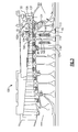
- Figure 3 shows another embodiment 130.
- Embodiment 130 operates in the Figure 2A and 2B conditions in a similar fashion. That is, the Figure 3 valve would communicate the hot air source 107 inwardly, and to preheat the chambers 119, as in the Figure 2A operation. Again, at some point, the valve 132 would then be moved to communicate the air source 108 to the chambers inwardly to the chambers 119. As in the prior embodiment, the change may happen shortly after being moved to high power operation of the associated engine.
- the embodiment 130 operates differently from the embodiments of Figures 2A-2C .
- the control 134 directs at least the hotter air source 107 through a valve 132 that may be actually mounted in the compressor exit 133.
- the control 134 may move the valve to tap the air as shown at 136 radially inward of the blades 104 and 106.
- the air then passes through the ports 138 in the hubs 102 and 103, and into anti-vortex tubes 140 before passing along the inner periphery at 142, and to the turbine at 144.
Landscapes
- Engineering & Computer Science (AREA)
- Mechanical Engineering (AREA)
- General Engineering & Computer Science (AREA)
- Chemical & Material Sciences (AREA)
- Combustion & Propulsion (AREA)
- Physics & Mathematics (AREA)
- Fluid Mechanics (AREA)
- Structures Of Non-Positive Displacement Pumps (AREA)
Applications Claiming Priority (1)
| Application Number | Priority Date | Filing Date | Title |
|---|---|---|---|
| US201462075281P | 2014-11-05 | 2014-11-05 |
Publications (2)
| Publication Number | Publication Date |
|---|---|
| EP3018288A1 true EP3018288A1 (de) | 2016-05-11 |
| EP3018288B1 EP3018288B1 (de) | 2019-05-01 |
Family
ID=54396786
Family Applications (1)
| Application Number | Title | Priority Date | Filing Date |
|---|---|---|---|
| EP15192939.5A Active EP3018288B1 (de) | 2014-11-05 | 2015-11-04 | Hochdruckkompressorrotorwärmekonditionierung mittels ausströmdruckluft und ein entsprechendes verfahren |
Country Status (2)
| Country | Link |
|---|---|
| US (1) | US10107206B2 (de) |
| EP (1) | EP3018288B1 (de) |
Cited By (3)
| Publication number | Priority date | Publication date | Assignee | Title |
|---|---|---|---|---|
| EP3388625A1 (de) * | 2017-04-11 | 2018-10-17 | United Technologies Corporation | Gekühlte kühlluft zur schaufelaussenluftabdichtung durch eine statorschaufel |
| EP3508688A1 (de) * | 2018-01-08 | 2019-07-10 | United Technologies Corporation | Gasturbinentriebwerk und verdichter |
| EP3524777A1 (de) * | 2018-02-07 | 2019-08-14 | United Technologies Corporation | Hochdruckverdichterrotorpaket und zugehöriger gasturbinenmotor |
Families Citing this family (12)
| Publication number | Priority date | Publication date | Assignee | Title |
|---|---|---|---|---|
| US10018120B2 (en) * | 2013-02-19 | 2018-07-10 | United Technologies Corporation | Gas turbine engine control for rotor bore heating |
| EP2995769B1 (de) * | 2014-09-12 | 2019-11-13 | United Technologies Corporation | Wärmeregelungssysteme eines turbomaschinenrotors |
| US10774742B2 (en) * | 2018-03-21 | 2020-09-15 | Raytheon Technologies Corporation | Flared anti-vortex tube rotor insert |
| US11274599B2 (en) | 2019-03-27 | 2022-03-15 | Pratt & Whitney Canada Corp. | Air system switching system to allow aero-engines to operate in standby mode |
| US11391219B2 (en) | 2019-04-18 | 2022-07-19 | Pratt & Whitney Canada Corp. | Health monitor for air switching system |
| US11274611B2 (en) | 2019-05-31 | 2022-03-15 | Pratt & Whitney Canada Corp. | Control logic for gas turbine engine fuel economy |
| US11859563B2 (en) | 2019-05-31 | 2024-01-02 | Pratt & Whitney Canada Corp. | Air system of multi-engine aircraft |
| US11326525B2 (en) | 2019-10-11 | 2022-05-10 | Pratt & Whitney Canada Corp. | Aircraft bleed air systems and methods |
| US11339673B2 (en) * | 2020-01-17 | 2022-05-24 | Raytheon Technologies Corporation | Rotor assembly with internal vanes |
| US11512594B2 (en) | 2020-06-05 | 2022-11-29 | General Electric Company | System and method for modulating airflow into a bore of a rotor to control blade tip clearance |
| US11525400B2 (en) | 2020-07-08 | 2022-12-13 | General Electric Company | System for rotor assembly thermal gradient reduction |
| CN120317188B (zh) * | 2025-06-13 | 2025-11-14 | 中国航发四川燃气涡轮研究院 | 一种缩短航空发动机启动暖机时间的引气结构及设计方法 |
Citations (7)
| Publication number | Priority date | Publication date | Assignee | Title |
|---|---|---|---|---|
| EP0141770A1 (de) * | 1983-11-03 | 1985-05-15 | United Technologies Corporation | Aktive Rotorspielregelung |
| US6267553B1 (en) * | 1999-06-01 | 2001-07-31 | Joseph C. Burge | Gas turbine compressor spool with structural and thermal upgrades |
| EP2206884A2 (de) * | 2009-01-09 | 2010-07-14 | General Electric Company | Rotorkühlkreislauf |
| US20110129332A1 (en) * | 2008-07-01 | 2011-06-02 | Snecma | Axial-centrifugal compressor having system for controlling play |
| EP2604825A2 (de) * | 2011-12-14 | 2013-06-19 | Rolls-Royce plc | Regler zum Kühlen der Turbinensektion eines Gasturbinentriebwerks |
| US20130192253A1 (en) * | 2012-01-31 | 2013-08-01 | William K. Ackermann | Gas turbine engine buffer system providing zoned ventilation |
| US20130323010A1 (en) * | 2012-05-31 | 2013-12-05 | United Technologies Corporation | Turbine coolant supply system |
-
2015
- 2015-10-08 US US14/878,018 patent/US10107206B2/en active Active
- 2015-11-04 EP EP15192939.5A patent/EP3018288B1/de active Active
Patent Citations (7)
| Publication number | Priority date | Publication date | Assignee | Title |
|---|---|---|---|---|
| EP0141770A1 (de) * | 1983-11-03 | 1985-05-15 | United Technologies Corporation | Aktive Rotorspielregelung |
| US6267553B1 (en) * | 1999-06-01 | 2001-07-31 | Joseph C. Burge | Gas turbine compressor spool with structural and thermal upgrades |
| US20110129332A1 (en) * | 2008-07-01 | 2011-06-02 | Snecma | Axial-centrifugal compressor having system for controlling play |
| EP2206884A2 (de) * | 2009-01-09 | 2010-07-14 | General Electric Company | Rotorkühlkreislauf |
| EP2604825A2 (de) * | 2011-12-14 | 2013-06-19 | Rolls-Royce plc | Regler zum Kühlen der Turbinensektion eines Gasturbinentriebwerks |
| US20130192253A1 (en) * | 2012-01-31 | 2013-08-01 | William K. Ackermann | Gas turbine engine buffer system providing zoned ventilation |
| US20130323010A1 (en) * | 2012-05-31 | 2013-12-05 | United Technologies Corporation | Turbine coolant supply system |
Cited By (6)
| Publication number | Priority date | Publication date | Assignee | Title |
|---|---|---|---|---|
| EP3388625A1 (de) * | 2017-04-11 | 2018-10-17 | United Technologies Corporation | Gekühlte kühlluft zur schaufelaussenluftabdichtung durch eine statorschaufel |
| US10711640B2 (en) | 2017-04-11 | 2020-07-14 | Raytheon Technologies Corporation | Cooled cooling air to blade outer air seal passing through a static vane |
| EP3508688A1 (de) * | 2018-01-08 | 2019-07-10 | United Technologies Corporation | Gasturbinentriebwerk und verdichter |
| US10767485B2 (en) | 2018-01-08 | 2020-09-08 | Raytheon Technologies Corporation | Radial cooling system for gas turbine engine compressors |
| EP3524777A1 (de) * | 2018-02-07 | 2019-08-14 | United Technologies Corporation | Hochdruckverdichterrotorpaket und zugehöriger gasturbinenmotor |
| US10563672B2 (en) | 2018-02-07 | 2020-02-18 | United Technologies Corporation | Gas turbine engine compressor |
Also Published As
| Publication number | Publication date |
|---|---|
| US20160123234A1 (en) | 2016-05-05 |
| US10107206B2 (en) | 2018-10-23 |
| EP3018288B1 (de) | 2019-05-01 |
Similar Documents
| Publication | Publication Date | Title |
|---|---|---|
| US10107206B2 (en) | High pressure compressor rotor thermal conditioning using discharge pressure air | |
| US11512651B2 (en) | Intercooled cooling air with auxiliary compressor control | |
| US11236675B2 (en) | Gas turbine engine with intercooled cooling air and turbine drive | |
| EP2952698B1 (de) | Turbinenstufenkühlung | |
| EP2952681B1 (de) | Turbinenstufenkühlung und dazugehöriges verfahren | |
| US9188009B2 (en) | Bore cavity thermal conditioning system | |
| US11268530B2 (en) | Variable speed boost compressor for gas turbine engine cooling air supply | |
| US20190063325A1 (en) | Intercooled cooling air using cooling compressor as starter | |
| US20190242407A1 (en) | Gas turbine engine compressor | |
| EP2959109B1 (de) | Gasturbinenmotor mit rotorscheibenbohrungsbeheizung | |
| EP3287620B1 (de) | Kompressor für motorkühlkreislauf | |
| EP3199779B1 (de) | Kühlluft für turbine mit veränderlichem querschnitt | |
| EP3572645B1 (de) | Verbesserte nachgeschaltete turbinenschaufelkühlung für einen gasturbinenmotor | |
| EP3015645B1 (de) | Hochdruckkompressorrotorwärmekonditionierung mittels aussendurchmessergasextraktion | |
| EP3232032B1 (de) | Kühlluft-system kompakter grösse mit leistungsverbesserung | |
| EP3056668B1 (de) | Wärmekonditionierung eines hochdruckverdichterrotors unter verwendung von aufbereiteter gekühlter luft | |
| EP3351767B1 (de) | Zwischengekühltes kühlluftsystem mit bypass | |
| EP3179034B1 (de) | Turbinenkühlluft mit mehreren quellen |
Legal Events
| Date | Code | Title | Description |
|---|---|---|---|
| PUAI | Public reference made under article 153(3) epc to a published international application that has entered the european phase |
Free format text: ORIGINAL CODE: 0009012 |
|
| AK | Designated contracting states |
Kind code of ref document: A1 Designated state(s): AL AT BE BG CH CY CZ DE DK EE ES FI FR GB GR HR HU IE IS IT LI LT LU LV MC MK MT NL NO PL PT RO RS SE SI SK SM TR |
|
| AX | Request for extension of the european patent |
Extension state: BA ME |
|
| RIN1 | Information on inventor provided before grant (corrected) |
Inventor name: HIESTER, PAUL J. Inventor name: FORCIER, MATTHEW P. Inventor name: MURPHY, ANDREW J. |
|
| RAP1 | Party data changed (applicant data changed or rights of an application transferred) |
Owner name: UNITED TECHNOLOGIES CORPORATION |
|
| STAA | Information on the status of an ep patent application or granted ep patent |
Free format text: STATUS: REQUEST FOR EXAMINATION WAS MADE |
|
| 17P | Request for examination filed |
Effective date: 20161109 |
|
| RBV | Designated contracting states (corrected) |
Designated state(s): AL AT BE BG CH CY CZ DE DK EE ES FI FR GB GR HR HU IE IS IT LI LT LU LV MC MK MT NL NO PL PT RO RS SE SI SK SM TR |
|
| GRAP | Despatch of communication of intention to grant a patent |
Free format text: ORIGINAL CODE: EPIDOSNIGR1 |
|
| STAA | Information on the status of an ep patent application or granted ep patent |
Free format text: STATUS: GRANT OF PATENT IS INTENDED |
|
| INTG | Intention to grant announced |
Effective date: 20180813 |
|
| GRAJ | Information related to disapproval of communication of intention to grant by the applicant or resumption of examination proceedings by the epo deleted |
Free format text: ORIGINAL CODE: EPIDOSDIGR1 |
|
| STAA | Information on the status of an ep patent application or granted ep patent |
Free format text: STATUS: REQUEST FOR EXAMINATION WAS MADE |
|
| GRAS | Grant fee paid |
Free format text: ORIGINAL CODE: EPIDOSNIGR3 |
|
| STAA | Information on the status of an ep patent application or granted ep patent |
Free format text: STATUS: GRANT OF PATENT IS INTENDED |
|
| GRAP | Despatch of communication of intention to grant a patent |
Free format text: ORIGINAL CODE: EPIDOSNIGR1 |
|
| INTC | Intention to grant announced (deleted) | ||
| INTG | Intention to grant announced |
Effective date: 20190116 |
|
| GRAA | (expected) grant |
Free format text: ORIGINAL CODE: 0009210 |
|
| STAA | Information on the status of an ep patent application or granted ep patent |
Free format text: STATUS: THE PATENT HAS BEEN GRANTED |
|
| AK | Designated contracting states |
Kind code of ref document: B1 Designated state(s): AL AT BE BG CH CY CZ DE DK EE ES FI FR GB GR HR HU IE IS IT LI LT LU LV MC MK MT NL NO PL PT RO RS SE SI SK SM TR |
|
| REG | Reference to a national code |
Ref country code: GB Ref legal event code: FG4D |
|
| REG | Reference to a national code |
Ref country code: CH Ref legal event code: EP Ref country code: AT Ref legal event code: REF Ref document number: 1127146 Country of ref document: AT Kind code of ref document: T Effective date: 20190515 |
|
| REG | Reference to a national code |
Ref country code: DE Ref legal event code: R096 Ref document number: 602015029219 Country of ref document: DE |
|
| REG | Reference to a national code |
Ref country code: IE Ref legal event code: FG4D |
|
| REG | Reference to a national code |
Ref country code: NL Ref legal event code: MP Effective date: 20190501 |
|
| REG | Reference to a national code |
Ref country code: LT Ref legal event code: MG4D |
|
| PG25 | Lapsed in a contracting state [announced via postgrant information from national office to epo] |
Ref country code: LT Free format text: LAPSE BECAUSE OF FAILURE TO SUBMIT A TRANSLATION OF THE DESCRIPTION OR TO PAY THE FEE WITHIN THE PRESCRIBED TIME-LIMIT Effective date: 20190501 Ref country code: ES Free format text: LAPSE BECAUSE OF FAILURE TO SUBMIT A TRANSLATION OF THE DESCRIPTION OR TO PAY THE FEE WITHIN THE PRESCRIBED TIME-LIMIT Effective date: 20190501 Ref country code: NL Free format text: LAPSE BECAUSE OF FAILURE TO SUBMIT A TRANSLATION OF THE DESCRIPTION OR TO PAY THE FEE WITHIN THE PRESCRIBED TIME-LIMIT Effective date: 20190501 Ref country code: SE Free format text: LAPSE BECAUSE OF FAILURE TO SUBMIT A TRANSLATION OF THE DESCRIPTION OR TO PAY THE FEE WITHIN THE PRESCRIBED TIME-LIMIT Effective date: 20190501 Ref country code: HR Free format text: LAPSE BECAUSE OF FAILURE TO SUBMIT A TRANSLATION OF THE DESCRIPTION OR TO PAY THE FEE WITHIN THE PRESCRIBED TIME-LIMIT Effective date: 20190501 Ref country code: PT Free format text: LAPSE BECAUSE OF FAILURE TO SUBMIT A TRANSLATION OF THE DESCRIPTION OR TO PAY THE FEE WITHIN THE PRESCRIBED TIME-LIMIT Effective date: 20190901 Ref country code: NO Free format text: LAPSE BECAUSE OF FAILURE TO SUBMIT A TRANSLATION OF THE DESCRIPTION OR TO PAY THE FEE WITHIN THE PRESCRIBED TIME-LIMIT Effective date: 20190801 Ref country code: AL Free format text: LAPSE BECAUSE OF FAILURE TO SUBMIT A TRANSLATION OF THE DESCRIPTION OR TO PAY THE FEE WITHIN THE PRESCRIBED TIME-LIMIT Effective date: 20190501 Ref country code: FI Free format text: LAPSE BECAUSE OF FAILURE TO SUBMIT A TRANSLATION OF THE DESCRIPTION OR TO PAY THE FEE WITHIN THE PRESCRIBED TIME-LIMIT Effective date: 20190501 |
|
| PG25 | Lapsed in a contracting state [announced via postgrant information from national office to epo] |
Ref country code: RS Free format text: LAPSE BECAUSE OF FAILURE TO SUBMIT A TRANSLATION OF THE DESCRIPTION OR TO PAY THE FEE WITHIN THE PRESCRIBED TIME-LIMIT Effective date: 20190501 Ref country code: LV Free format text: LAPSE BECAUSE OF FAILURE TO SUBMIT A TRANSLATION OF THE DESCRIPTION OR TO PAY THE FEE WITHIN THE PRESCRIBED TIME-LIMIT Effective date: 20190501 Ref country code: GR Free format text: LAPSE BECAUSE OF FAILURE TO SUBMIT A TRANSLATION OF THE DESCRIPTION OR TO PAY THE FEE WITHIN THE PRESCRIBED TIME-LIMIT Effective date: 20190802 Ref country code: BG Free format text: LAPSE BECAUSE OF FAILURE TO SUBMIT A TRANSLATION OF THE DESCRIPTION OR TO PAY THE FEE WITHIN THE PRESCRIBED TIME-LIMIT Effective date: 20190801 |
|
| REG | Reference to a national code |
Ref country code: AT Ref legal event code: MK05 Ref document number: 1127146 Country of ref document: AT Kind code of ref document: T Effective date: 20190501 |
|
| PG25 | Lapsed in a contracting state [announced via postgrant information from national office to epo] |
Ref country code: IS Free format text: LAPSE BECAUSE OF FAILURE TO SUBMIT A TRANSLATION OF THE DESCRIPTION OR TO PAY THE FEE WITHIN THE PRESCRIBED TIME-LIMIT Effective date: 20190901 |
|
| PG25 | Lapsed in a contracting state [announced via postgrant information from national office to epo] |
Ref country code: RO Free format text: LAPSE BECAUSE OF FAILURE TO SUBMIT A TRANSLATION OF THE DESCRIPTION OR TO PAY THE FEE WITHIN THE PRESCRIBED TIME-LIMIT Effective date: 20190501 Ref country code: CZ Free format text: LAPSE BECAUSE OF FAILURE TO SUBMIT A TRANSLATION OF THE DESCRIPTION OR TO PAY THE FEE WITHIN THE PRESCRIBED TIME-LIMIT Effective date: 20190501 Ref country code: SK Free format text: LAPSE BECAUSE OF FAILURE TO SUBMIT A TRANSLATION OF THE DESCRIPTION OR TO PAY THE FEE WITHIN THE PRESCRIBED TIME-LIMIT Effective date: 20190501 Ref country code: DK Free format text: LAPSE BECAUSE OF FAILURE TO SUBMIT A TRANSLATION OF THE DESCRIPTION OR TO PAY THE FEE WITHIN THE PRESCRIBED TIME-LIMIT Effective date: 20190501 Ref country code: AT Free format text: LAPSE BECAUSE OF FAILURE TO SUBMIT A TRANSLATION OF THE DESCRIPTION OR TO PAY THE FEE WITHIN THE PRESCRIBED TIME-LIMIT Effective date: 20190501 Ref country code: EE Free format text: LAPSE BECAUSE OF FAILURE TO SUBMIT A TRANSLATION OF THE DESCRIPTION OR TO PAY THE FEE WITHIN THE PRESCRIBED TIME-LIMIT Effective date: 20190501 |
|
| REG | Reference to a national code |
Ref country code: DE Ref legal event code: R097 Ref document number: 602015029219 Country of ref document: DE |
|
| PG25 | Lapsed in a contracting state [announced via postgrant information from national office to epo] |
Ref country code: IT Free format text: LAPSE BECAUSE OF FAILURE TO SUBMIT A TRANSLATION OF THE DESCRIPTION OR TO PAY THE FEE WITHIN THE PRESCRIBED TIME-LIMIT Effective date: 20190501 Ref country code: SM Free format text: LAPSE BECAUSE OF FAILURE TO SUBMIT A TRANSLATION OF THE DESCRIPTION OR TO PAY THE FEE WITHIN THE PRESCRIBED TIME-LIMIT Effective date: 20190501 |
|
| PLBE | No opposition filed within time limit |
Free format text: ORIGINAL CODE: 0009261 |
|
| STAA | Information on the status of an ep patent application or granted ep patent |
Free format text: STATUS: NO OPPOSITION FILED WITHIN TIME LIMIT |
|
| PG25 | Lapsed in a contracting state [announced via postgrant information from national office to epo] |
Ref country code: TR Free format text: LAPSE BECAUSE OF FAILURE TO SUBMIT A TRANSLATION OF THE DESCRIPTION OR TO PAY THE FEE WITHIN THE PRESCRIBED TIME-LIMIT Effective date: 20190501 |
|
| 26N | No opposition filed |
Effective date: 20200204 |
|
| PG25 | Lapsed in a contracting state [announced via postgrant information from national office to epo] |
Ref country code: PL Free format text: LAPSE BECAUSE OF FAILURE TO SUBMIT A TRANSLATION OF THE DESCRIPTION OR TO PAY THE FEE WITHIN THE PRESCRIBED TIME-LIMIT Effective date: 20190501 |
|
| PG25 | Lapsed in a contracting state [announced via postgrant information from national office to epo] |
Ref country code: SI Free format text: LAPSE BECAUSE OF FAILURE TO SUBMIT A TRANSLATION OF THE DESCRIPTION OR TO PAY THE FEE WITHIN THE PRESCRIBED TIME-LIMIT Effective date: 20190501 |
|
| REG | Reference to a national code |
Ref country code: CH Ref legal event code: PL |
|
| PG25 | Lapsed in a contracting state [announced via postgrant information from national office to epo] |
Ref country code: LU Free format text: LAPSE BECAUSE OF NON-PAYMENT OF DUE FEES Effective date: 20191104 Ref country code: MC Free format text: LAPSE BECAUSE OF FAILURE TO SUBMIT A TRANSLATION OF THE DESCRIPTION OR TO PAY THE FEE WITHIN THE PRESCRIBED TIME-LIMIT Effective date: 20190501 Ref country code: CH Free format text: LAPSE BECAUSE OF NON-PAYMENT OF DUE FEES Effective date: 20191130 Ref country code: LI Free format text: LAPSE BECAUSE OF NON-PAYMENT OF DUE FEES Effective date: 20191130 |
|
| REG | Reference to a national code |
Ref country code: BE Ref legal event code: MM Effective date: 20191130 |
|
| PG25 | Lapsed in a contracting state [announced via postgrant information from national office to epo] |
Ref country code: IE Free format text: LAPSE BECAUSE OF NON-PAYMENT OF DUE FEES Effective date: 20191104 |
|
| PG25 | Lapsed in a contracting state [announced via postgrant information from national office to epo] |
Ref country code: BE Free format text: LAPSE BECAUSE OF NON-PAYMENT OF DUE FEES Effective date: 20191130 |
|
| PG25 | Lapsed in a contracting state [announced via postgrant information from national office to epo] |
Ref country code: CY Free format text: LAPSE BECAUSE OF FAILURE TO SUBMIT A TRANSLATION OF THE DESCRIPTION OR TO PAY THE FEE WITHIN THE PRESCRIBED TIME-LIMIT Effective date: 20190501 |
|
| PG25 | Lapsed in a contracting state [announced via postgrant information from national office to epo] |
Ref country code: HU Free format text: LAPSE BECAUSE OF FAILURE TO SUBMIT A TRANSLATION OF THE DESCRIPTION OR TO PAY THE FEE WITHIN THE PRESCRIBED TIME-LIMIT; INVALID AB INITIO Effective date: 20151104 Ref country code: MT Free format text: LAPSE BECAUSE OF FAILURE TO SUBMIT A TRANSLATION OF THE DESCRIPTION OR TO PAY THE FEE WITHIN THE PRESCRIBED TIME-LIMIT Effective date: 20190501 |
|
| PG25 | Lapsed in a contracting state [announced via postgrant information from national office to epo] |
Ref country code: MK Free format text: LAPSE BECAUSE OF FAILURE TO SUBMIT A TRANSLATION OF THE DESCRIPTION OR TO PAY THE FEE WITHIN THE PRESCRIBED TIME-LIMIT Effective date: 20190501 |
|
| REG | Reference to a national code |
Ref country code: DE Ref legal event code: R081 Ref document number: 602015029219 Country of ref document: DE Owner name: RAYTHEON TECHNOLOGIES CORPORATION (N.D.GES.D.S, US Free format text: FORMER OWNER: UNITED TECHNOLOGIES CORPORATION, FARMINGTON, CONN., US Ref country code: DE Ref legal event code: R081 Ref document number: 602015029219 Country of ref document: DE Owner name: RTX CORPORATION (N.D.GES.D. STAATES DELAWARE),, US Free format text: FORMER OWNER: UNITED TECHNOLOGIES CORPORATION, FARMINGTON, CONN., US |
|
| P01 | Opt-out of the competence of the unified patent court (upc) registered |
Effective date: 20230520 |
|
| REG | Reference to a national code |
Ref country code: DE Ref legal event code: R081 Ref document number: 602015029219 Country of ref document: DE Owner name: RTX CORPORATION (N.D.GES.D. STAATES DELAWARE),, US Free format text: FORMER OWNER: RAYTHEON TECHNOLOGIES CORPORATION (N.D.GES.D.STAATES DELAWARE), ARLINGTON, VA, US |
|
| PGFP | Annual fee paid to national office [announced via postgrant information from national office to epo] |
Ref country code: DE Payment date: 20251022 Year of fee payment: 11 |
|
| PGFP | Annual fee paid to national office [announced via postgrant information from national office to epo] |
Ref country code: GB Payment date: 20251023 Year of fee payment: 11 |
|
| PGFP | Annual fee paid to national office [announced via postgrant information from national office to epo] |
Ref country code: FR Payment date: 20251023 Year of fee payment: 11 |