EP3018330B1 - Brennkraftmaschine - Google Patents
Brennkraftmaschine Download PDFInfo
- Publication number
- EP3018330B1 EP3018330B1 EP15188088.7A EP15188088A EP3018330B1 EP 3018330 B1 EP3018330 B1 EP 3018330B1 EP 15188088 A EP15188088 A EP 15188088A EP 3018330 B1 EP3018330 B1 EP 3018330B1
- Authority
- EP
- European Patent Office
- Prior art keywords
- water
- internal combustion
- combustion engine
- injector
- water injector
- Prior art date
- Legal status (The legal status is an assumption and is not a legal conclusion. Google has not performed a legal analysis and makes no representation as to the accuracy of the status listed.)
- Active
Links
Images

Classifications
-
- F—MECHANICAL ENGINEERING; LIGHTING; HEATING; WEAPONS; BLASTING
- F02—COMBUSTION ENGINES; HOT-GAS OR COMBUSTION-PRODUCT ENGINE PLANTS
- F02M—SUPPLYING COMBUSTION ENGINES IN GENERAL WITH COMBUSTIBLE MIXTURES OR CONSTITUENTS THEREOF
- F02M25/00—Engine-pertinent apparatus for adding non-fuel substances or small quantities of secondary fuel to combustion-air, main fuel or fuel-air mixture
- F02M25/022—Adding fuel and water emulsion, water or steam
- F02M25/025—Adding water
- F02M25/028—Adding water into the charge intakes
-
- F—MECHANICAL ENGINEERING; LIGHTING; HEATING; WEAPONS; BLASTING
- F02—COMBUSTION ENGINES; HOT-GAS OR COMBUSTION-PRODUCT ENGINE PLANTS
- F02B—INTERNAL-COMBUSTION PISTON ENGINES; COMBUSTION ENGINES IN GENERAL
- F02B47/00—Methods of operating engines involving adding non-fuel substances or anti-knock agents to combustion air, fuel, or fuel-air mixtures of engines
- F02B47/02—Methods of operating engines involving adding non-fuel substances or anti-knock agents to combustion air, fuel, or fuel-air mixtures of engines the substances being water or steam
-
- F—MECHANICAL ENGINEERING; LIGHTING; HEATING; WEAPONS; BLASTING
- F02—COMBUSTION ENGINES; HOT-GAS OR COMBUSTION-PRODUCT ENGINE PLANTS
- F02M—SUPPLYING COMBUSTION ENGINES IN GENERAL WITH COMBUSTIBLE MIXTURES OR CONSTITUENTS THEREOF
- F02M25/00—Engine-pertinent apparatus for adding non-fuel substances or small quantities of secondary fuel to combustion-air, main fuel or fuel-air mixture
- F02M25/022—Adding fuel and water emulsion, water or steam
- F02M25/0221—Details of the water supply system, e.g. pumps or arrangement of valves
-
- Y—GENERAL TAGGING OF NEW TECHNOLOGICAL DEVELOPMENTS; GENERAL TAGGING OF CROSS-SECTIONAL TECHNOLOGIES SPANNING OVER SEVERAL SECTIONS OF THE IPC; TECHNICAL SUBJECTS COVERED BY FORMER USPC CROSS-REFERENCE ART COLLECTIONS [XRACs] AND DIGESTS
- Y02—TECHNOLOGIES OR APPLICATIONS FOR MITIGATION OR ADAPTATION AGAINST CLIMATE CHANGE
- Y02T—CLIMATE CHANGE MITIGATION TECHNOLOGIES RELATED TO TRANSPORTATION
- Y02T10/00—Road transport of goods or passengers
- Y02T10/10—Internal combustion engine [ICE] based vehicles
- Y02T10/12—Improving ICE efficiencies
Definitions
- the invention relates to an internal combustion engine with at least one cylinder, wherein the cylinder is connected via a vibration tube with an air collector, and with a water injector.
- Similar internal combustion engines are from the WO 2006/052719 A2 and the US 6 637 382 B1 known.
- Such an internal combustion engine is known.
- the injected into the combustion chamber water reduces the tendency to knock the engine and avoids a mixture enrichment to limit the exhaust gas temperature.
- the water can be introduced through different systems in the cylinder, among other things, by the fact that the water is injected into the intake manifold.
- the water is injected via an injector located near the intake valves.
- the water injector is arranged opposite the vibration tube.
- the water injector is aligned with the vibration tube so that it injects substantially axially into the vibration tube.
- the water injector is designed as a swirl injector.
- the water consumption can be reduced because a larger proportion of water flows liquid into the combustion chamber and does not cool the inlet channel and the inlet valve as a wall film.
- the cyclic variations due to wall film effects can also be reduced.
- FIG. 1 the schematic structure of an internal combustion engine 1 is shown with a water injection.
- the internal combustion engine 1 has a plurality of cylinders 2, which are each connected via a vibration tube 3 with an air collector 4.
- a water injector 5 is arranged for each cylinder 2 and each vibration tube 3.
- the water injectors 5 are connected via a line 6 to a water pump 7, which in turn communicates with a water tank 8.
- a heater 10 is present in the water tank. Between the water pump 7 and the water tank 8, a bypass valve 11 may be provided.
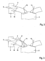
- FIG. 2 a detail of the internal combustion engine 1 is shown.
- the inlet valve 12 is connected to the air collector 4 via the vibration tube 3.
- the water injector 5 is arranged such that it faces the vibration tube 3 and the water 14 injects substantially axially into the vibration tube 3.
- FIG. 3 shows a comparison of the position of the water injector 5 in the inventive arrangement (left) and the water injector 5 'in the conventional standard intake manifold injection (right).
- the water injector 5 ' is disposed upstream of a channel branch 15 at which the swing pipe 3 and the suction pipe branch. This positioning also leads to a wall contact of the water with the inner channel walls and thus to a wall film structure in a two-jet injector. Furthermore, the spray angle is limited.
- the inventive positioning of the water injector 5 in the air collector 4 with respect to the vibration tube 3 allows a flat injection, which leads to a spray geometry with a large opening angle, since the channel cross section in this area is significantly greater than in the conventional positioning of the water injector 5 'in intake manifold.
- a swirl injector with a hollow cone spray and a better droplet spectrum can also be used. Due to the greater distance from the channel junction 15, the drop in the fall when passing through the channel junction 15 has progressed, and the wall contact is less pronounced. Thus, a larger proportion of the injected water 14 passes directly into the combustion chamber and cools the mixture more effectively than in the conventional positioning, the by increased wall contact and impingement of individual drops on the inlet valve 12, these components preferably cools.
Landscapes
- Engineering & Computer Science (AREA)
- Chemical & Material Sciences (AREA)
- Combustion & Propulsion (AREA)
- Mechanical Engineering (AREA)
- General Engineering & Computer Science (AREA)
- Health & Medical Sciences (AREA)
- Public Health (AREA)
- Water Supply & Treatment (AREA)
- Output Control And Ontrol Of Special Type Engine (AREA)
- Fuel-Injection Apparatus (AREA)
Description
- Die Erfindung betrifft eine Brennkraftmaschine mit mindestens einem Zylinder, wobei der Zylinder über ein Schwingrohr mit einem Luftsammler verbunden ist, und mit einem Wasserinjektor. Ähnliche Brennkraftmaschinen sind aus der
WO 2006/052719 A2 und derUS 6 637 382 B1 bekannt. - Eine derartige Brennkraftmaschine ist bekannt. Das in den Brennraum eingespritzte Wasser vermindert die Klopfneigung des Motors und vermeidet eine Gemischanreicherung zur Begrenzung der Abgastemperatur. Das Wasser kann durch unterschiedliche Systeme in den Zylinder eingebracht werden, unter anderem dadurch, dass das Wasser in das Saugrohr eingespritzt wird.
- Bei einer derartigen Saugrohreinspritzung wird das Wasser über einen Injektor eingespritzt, der in der Nähe der Einlassventile angeordnet ist.
- Dies führt jedoch dazu, dass häufig die Wände des Einlasskanals und die Ventilteller benetzt werden. Demzufolge gelangt nur ein geringer Teil des Wassers direkt in den Brennraum. Darüber hinaus wird die Menge des Wassers durch einen Wandfilm zyklusabhängig schwer kontrollierbar.
- Es ist daher Aufgabe der vorliegenden Erfindung, hier Abhilfe zu schaffen.
- Diese Aufgabe wird durch die Merkmalskombination des unabhängigen Anspruches 1 gelöst.
- Infolge dieser Ausgestaltung können die Wassertropfen besser der Luftströmung folgen, und die Bildung eines Wandfilms kann vermindert werden.
- Erfindungsgemäß ist der Wasserinjektor gegenüber dem Schwingrohr angeordnet.
- Erfindungsgemäß ist der Wasserinjektor so zu dem Schwingrohr ausgerichtet, dass er im Wesentlichen axial in das Schwingrohr einspritzt.
- Vorteilhafterweise ist der Wasserinjektor als Drallinjektor ausgebildet.
- Mit einer Positionierung des Wasserinjektors im Luftsammler gegenüber dem Schwingrohr lässt sich der Wasserverbrauch reduzieren, da ein größerer Wasseranteil flüssig in den Brennraum gelangt und nicht als Wandfilm den Einlasskanal und das Einlassventil kühlt. Die zyklischen Schwankungen durch Wandfilmeffekte lassen sich ebenfalls vermindern.
- Weitere Einzelheiten, Merkmale und Vorteile der Erfindung ergeben sich aus der nachfolgenden Beschreibung anhand der Zeichnungen. Es zeigen:
- Figur 1
- den schematischen Aufbau einer Brennkraftmaschine mit einer Wassereinspritzung,
- Figur 2
- eine Detailansicht im Bereich des Schwingrohres mit der erfindungsgemäßen Anordnung des Wasserinjektors, und
- Figur 3
- einen Vergleich zwischen einer herkömmlichen und der erfindungsgemäßen Anordnung des Wasserinjektors.
- In
Figur 1 ist der schematische Aufbau einer Brennkraftmaschine 1 mit einer Wassereinspritzung dargestellt. - Die Brennkraftmaschine 1 hat mehrere Zylindern 2, die jeweils über ein Schwingrohr 3 mit einem Luftsammler 4 verbunden sind. In dem Luftsammler 4 ist für jeden Zylinder 2 bzw. jedes Schwingrohr 3 ein Wasserinjektor 5 angeordnet. Die Wasserinjektoren 5sind über eine Leitung 6 mit einer Wasserpumpe 7 verbunden, die wiederum mit einem Wassertank 8 in Verbindung steht.
- In dem Wassertank 8 sind verschiedene Sensoren 9 angeordnet, welche z. B. den Füllstand, die Temperatur, die Leitfähigkeit des Wassers usw. überwachen. Außerdem ist in dem Wassertank eine Heizung 10 vorhanden. Zwischen der Wasserpumpe 7 und dem Wassertank 8 kann ein Bypassventil 11 vorgesehen sein.
- In
Figur 2 ist ein Detail der Brennkraftmaschine 1 dargestellt. Man erkennt einen Zylinder 2 mit einem Einlassventil 12 und einem Auslassventil 13. - Das Einlassventil 12 ist über das Schwingrohr 3 mit dem Luftsammler 4 verbunden. In dem Luftsammler 4 ist der Wasserinjektor 5 derart angeordnet, dass er dem Schwingrohr 3 gegenüber liegt und das Wasser 14 im Wesentlichen axial in das Schwingrohr 3 einspritzt.
-
Figur 3 zeigt einen Vergleich der Position des Wasserinjektors 5 bei der erfindungsgemäßen Anordnung (links) und des Wasserinjektors 5' bei der herkömmlichen Standard-Saugrohreinspritzung (rechts). - Bei der herkömmlichen Positionierung ist der Wasserinjektor 5' stromaufwärts einer Kanalverzweigung 15, an welcher sich Schwingrohr 3 und Saugrohr verzweigen, angeordnet. Diese Positionierung führt auch bei einem Zweistrahlinjektor zu einem Wandkontakt des Wassers mit den inneren Kanalwänden und damit zu einem Wandfilmaufbau. Ferner ist der Spraywinkel begrenzt.
- Im Gegensatz dazu ermöglicht die erfindungsgemäße Positionierung des Wasserinjektors 5 in dem Luftsammler 4 gegenüber dem Schwingrohr 3 eine Flacheinspritzung, die zu einer Spraygeometrie mit einem großem Öffnungswinkel führt, da der Kanalquerschnitt in diesem Bereich deutlich größer ist als bei der herkömmlichen Positionierung des Wasserinjektors 5' im Saugrohr. Erfindungsgemäß kann darüber hinaus auch ein Drallinjektor mit einem Hohlkegelspray und einem besserem Tropfenspektrum eingesetzt werden. Aufgrund der größeren Entfernung zur Kanalverzweigung 15 ist der Tropfenzerfall beim Passieren der Kanalverzweigung 15 fortgeschritten, und der Wandkontakt ist geringer ausgeprägt. Damit gelangt ein größerer Anteil des eingespritzten Wassers 14 direkt in den Brennraum und kühlt das Gemisch wirksamer als bei der herkömmlichen Positionierung, die durch vermehrten Wandkontakt und Auftreffen einzelner Tropfen auf dem Einlassventil 12 bevorzugt diese Bauteile kühlt.
- Die vorhergehende Beschreibung der vorliegenden Erfindung dient nur zu illustrativen Zwecken und nicht zum Zwecke der Beschränkung der Erfindung.
-
- 1
- Brennkraftmaschine
- 2
- Zylinder
- 3
- Schwingrohr
- 4
- Luftsammler
- 5
- Wasserinjektor
- 5'
- Wasserinjektor
- 6
- Leitung
- 7
- Wasserpumpe
- 8
- Wassertank
- 9
- Sensor
- 10
- Heizung
- 11
- Bypassventil
- 12
- Einlassventil
- 13
- Auslassventil
- 14
- Wasser
- 15
- Kanalverzweigung
Claims (2)
- Brennkraftmaschine mit mindestens einem Zylinder, wobei jeder Zylinder über ein Schwingrohr mit einem Luftsammler verbunden ist, dadurch gekennzeichnet, dass jedem Schwingrohr (3) ein in dem Luftsammler (4) angeordneter Wasserinjektor (5) gegenüber angeordnet und so zu dem Schwingrohr (3) ausgerichtet ist, dass er im Wesentlichen axial in das Schwingrohr (3) einspritzt.
- Brennkraftmaschine nach Anspruch 1, dadurch gekennzeichnet, dass der Wasserinjektor (4) als Drallinjektor ausgebildet ist.
Applications Claiming Priority (1)
| Application Number | Priority Date | Filing Date | Title |
|---|---|---|---|
| DE102014222466.7A DE102014222466A1 (de) | 2014-11-04 | 2014-11-04 | Brennkraftmaschine |
Publications (2)
| Publication Number | Publication Date |
|---|---|
| EP3018330A1 EP3018330A1 (de) | 2016-05-11 |
| EP3018330B1 true EP3018330B1 (de) | 2018-10-31 |
Family
ID=54260643
Family Applications (1)
| Application Number | Title | Priority Date | Filing Date |
|---|---|---|---|
| EP15188088.7A Active EP3018330B1 (de) | 2014-11-04 | 2015-10-02 | Brennkraftmaschine |
Country Status (3)
| Country | Link |
|---|---|
| EP (1) | EP3018330B1 (de) |
| CN (1) | CN105569882B (de) |
| DE (1) | DE102014222466A1 (de) |
Families Citing this family (5)
| Publication number | Priority date | Publication date | Assignee | Title |
|---|---|---|---|---|
| US10247140B2 (en) * | 2016-12-19 | 2019-04-02 | Ford Global Technologies, Llc | Methods and system for adjusting engine water injection |
| US10267243B2 (en) * | 2016-12-19 | 2019-04-23 | Ford Global Technologies, Llc | Method and system for pulsed engine water injection |
| DE102017200291A1 (de) * | 2017-01-10 | 2018-07-12 | Robert Bosch Gmbh | Wassereinspritzvorrichtung, insbesondere einer Brennkraftmaschine, und Verfahren zum Betreiben einer solchen Wassereinspritzvorrichtung |
| DE102017211826B3 (de) | 2017-07-11 | 2018-12-27 | Continental Automotive Gmbh | Vorrichtung zur Einspritzung von Wasser für eine Verbrennungskraftmaschine |
| DE102017011005A1 (de) | 2017-11-28 | 2019-05-29 | Daimler Ag | Verfahren zum Betreiben einer Dosiereinrichtung einer Verbrennungskraftmaschine für ein Kraftfahrzeug |
Citations (4)
| Publication number | Priority date | Publication date | Assignee | Title |
|---|---|---|---|---|
| DE7832077U1 (de) * | 1978-10-27 | 1980-02-07 | Bayerische Motoren Werke Ag, 8000 Muenchen | Einspritz-brennkraftmaschine |
| GB2146387A (en) * | 1983-09-09 | 1985-04-17 | Volvo Ab | Turbo charged combustion engine with water injection |
| DE4239842A1 (de) * | 1992-11-27 | 1994-06-01 | Bosch Gmbh Robert | Verfahren und Vorrichtung zur Steuerung einer Brennkraftmaschine |
| US20030168025A1 (en) * | 2002-03-11 | 2003-09-11 | Edward J. Lesniak | Electronic controlled emission and fluid injection system for an internal combustion engine |
Family Cites Families (10)
| Publication number | Priority date | Publication date | Assignee | Title |
|---|---|---|---|---|
| US2122414A (en) * | 1935-10-10 | 1938-07-05 | Samuel G Lipford | Gas saver for internal combustion engines |
| US6511052B1 (en) * | 1999-08-06 | 2003-01-28 | E. I. Du Pont De Nemours And Company | Humidifying gas induction or supply system |
| FI112692B (fi) * | 2000-11-03 | 2003-12-31 | Waertsilae Finland Oy | Menetelmä ja järjestely ahdetun mäntämoottorin typpioksidipäästöjen (NOx) vähentämiseksi |
| US6637382B1 (en) * | 2002-09-11 | 2003-10-28 | Ford Global Technologies, Llc | Turbocharger system for diesel engine |
| DE10338749B4 (de) * | 2003-08-23 | 2006-03-30 | Man B & W Diesel Ag | Vorrichtung zur Zufuhr von Wasser für eine aufgeladene Kolbenbrennkraftmaschine |
| WO2006052719A2 (en) * | 2004-11-04 | 2006-05-18 | S.I.S. Power, Inc. | Devices, systems and methods for controlling introduction of additives into an internal combustion engine |
| US7216607B2 (en) * | 2005-05-27 | 2007-05-15 | Rival Technologies Inc. | Emission control water injection system for diesel engines |
| SE0702231L (sv) * | 2007-10-03 | 2008-11-04 | Scania Cv Abp | Anordning för avledning av kondensat |
| DE102011005941A1 (de) * | 2011-03-23 | 2012-09-27 | Mahle International Gmbh | Brennkraftmaschine, Frischluftanlage und zugehöriges Betriebsverfahren |
| GB2497770A (en) * | 2011-12-21 | 2013-06-26 | Nissan Motor Mfg Uk Ltd | Charge-cooling an i.c. engine using captured air-conditioning condensate |
-
2014
- 2014-11-04 DE DE102014222466.7A patent/DE102014222466A1/de not_active Withdrawn
-
2015
- 2015-10-02 EP EP15188088.7A patent/EP3018330B1/de active Active
- 2015-10-27 CN CN201510705571.XA patent/CN105569882B/zh active Active
Patent Citations (4)
| Publication number | Priority date | Publication date | Assignee | Title |
|---|---|---|---|---|
| DE7832077U1 (de) * | 1978-10-27 | 1980-02-07 | Bayerische Motoren Werke Ag, 8000 Muenchen | Einspritz-brennkraftmaschine |
| GB2146387A (en) * | 1983-09-09 | 1985-04-17 | Volvo Ab | Turbo charged combustion engine with water injection |
| DE4239842A1 (de) * | 1992-11-27 | 1994-06-01 | Bosch Gmbh Robert | Verfahren und Vorrichtung zur Steuerung einer Brennkraftmaschine |
| US20030168025A1 (en) * | 2002-03-11 | 2003-09-11 | Edward J. Lesniak | Electronic controlled emission and fluid injection system for an internal combustion engine |
Also Published As
| Publication number | Publication date |
|---|---|
| CN105569882A (zh) | 2016-05-11 |
| EP3018330A1 (de) | 2016-05-11 |
| CN105569882B (zh) | 2019-12-10 |
| DE102014222466A1 (de) | 2016-05-04 |
Similar Documents
| Publication | Publication Date | Title |
|---|---|---|
| EP2370687B1 (de) | Brennkraftmaschine | |
| EP0489238B1 (de) | Ansaugverteiler für eine Brennkraftmaschine | |
| DE102018112450B4 (de) | Brennzylinder einer Brennkraftmaschine | |
| WO2016177561A1 (de) | Wassereinspritzvorrichtung für eine brennkraftmaschine und verfahren zum betreiben einer solchen wassereinspritzvorrichtung | |
| EP3018330A1 (de) | Brennkraftmaschine | |
| DE102009019978A1 (de) | Reinluftstrombrennstoffeinspritzeinrichtung | |
| DE102010036366A1 (de) | Kraftstoffeinspritzdüse zur Reduzierung der Verkokung | |
| DE102016214954A1 (de) | Gasförmiger Brennstoff, AGR und Luftmischvorrichtung plus Einsatz | |
| EP3346120B1 (de) | Wassereinspritzvorrichtung einer brennkraftmaschine und verfahren zum betreiben einer solchen wassereinspritzvorrichtung | |
| DE112011100573T5 (de) | Turbolader | |
| DE112016000257T5 (de) | Mischer für gasförmigen Brennstoff mit Abgasrückführung | |
| EP1778953B1 (de) | Reinigungsvorrichtung einer abgasturbine | |
| DE102015016244A1 (de) | Hitzeresistente Reduktionsmitteleinspritzdüse | |
| DE102019101435A1 (de) | Vorkammerzündvorrichtung und Motor, der dieselbe umfasst | |
| DE102015200455A1 (de) | Motor, Kraftfahrzeug, Einspritzverfahren | |
| DE102015007393B4 (de) | Abgasrückführungssystem für eine Brennkraftmaschine | |
| EP3018319A1 (de) | Zylinderkopfanordnung für einen verbrennungsmotor | |
| EP2370688B1 (de) | Kraftstoffeinspritzvorrichtung | |
| DE102019105033B4 (de) | System zur abgasrückführung | |
| DE102008019157B4 (de) | Verbrennungsmotor und Verfahren zu dessen Betrieb | |
| DE102017211826B3 (de) | Vorrichtung zur Einspritzung von Wasser für eine Verbrennungskraftmaschine | |
| DE102014018035A1 (de) | Luftleitung für einen Ansaugtrakt einer Verbrennungskraftmaschine | |
| DE102010064175A1 (de) | Einspritzsystem, Brennkraftmaschine und Verfahren zum Betrieb eines Einspritzsystems | |
| EP2529101B1 (de) | Einspritzvorrichtung mit reduzierten druckschwingungen | |
| DE102017005162A1 (de) | Injektor zum Einbringen von Kraftstoff in eine Verbrennungskraftmaschine, insbesondere eines Kraftfahrzeugs |
Legal Events
| Date | Code | Title | Description |
|---|---|---|---|
| PUAI | Public reference made under article 153(3) epc to a published international application that has entered the european phase |
Free format text: ORIGINAL CODE: 0009012 |
|
| AK | Designated contracting states |
Kind code of ref document: A1 Designated state(s): AL AT BE BG CH CY CZ DE DK EE ES FI FR GB GR HR HU IE IS IT LI LT LU LV MC MK MT NL NO PL PT RO RS SE SI SK SM TR |
|
| AX | Request for extension of the european patent |
Extension state: BA ME |
|
| 17P | Request for examination filed |
Effective date: 20160804 |
|
| RBV | Designated contracting states (corrected) |
Designated state(s): AL AT BE BG CH CY CZ DE DK EE ES FI FR GB GR HR HU IE IS IT LI LT LU LV MC MK MT NL NO PL PT RO RS SE SI SK SM TR |
|
| STAA | Information on the status of an ep patent application or granted ep patent |
Free format text: STATUS: EXAMINATION IS IN PROGRESS |
|
| 17Q | First examination report despatched |
Effective date: 20161207 |
|
| GRAP | Despatch of communication of intention to grant a patent |
Free format text: ORIGINAL CODE: EPIDOSNIGR1 |
|
| STAA | Information on the status of an ep patent application or granted ep patent |
Free format text: STATUS: GRANT OF PATENT IS INTENDED |
|
| RIC1 | Information provided on ipc code assigned before grant |
Ipc: F02M 25/028 20060101ALI20180517BHEP Ipc: F02M 25/022 20060101AFI20180517BHEP Ipc: F02B 47/02 20060101ALN20180517BHEP |
|
| INTG | Intention to grant announced |
Effective date: 20180612 |
|
| GRAS | Grant fee paid |
Free format text: ORIGINAL CODE: EPIDOSNIGR3 |
|
| GRAA | (expected) grant |
Free format text: ORIGINAL CODE: 0009210 |
|
| STAA | Information on the status of an ep patent application or granted ep patent |
Free format text: STATUS: THE PATENT HAS BEEN GRANTED |
|
| AK | Designated contracting states |
Kind code of ref document: B1 Designated state(s): AL AT BE BG CH CY CZ DE DK EE ES FI FR GB GR HR HU IE IS IT LI LT LU LV MC MK MT NL NO PL PT RO RS SE SI SK SM TR |
|
| REG | Reference to a national code |
Ref country code: CH Ref legal event code: EP Ref country code: GB Ref legal event code: FG4D Free format text: NOT ENGLISH |
|
| REG | Reference to a national code |
Ref country code: AT Ref legal event code: REF Ref document number: 1059715 Country of ref document: AT Kind code of ref document: T Effective date: 20181115 |
|
| REG | Reference to a national code |
Ref country code: DE Ref legal event code: R096 Ref document number: 502015006648 Country of ref document: DE |
|
| REG | Reference to a national code |
Ref country code: IE Ref legal event code: FG4D Free format text: LANGUAGE OF EP DOCUMENT: GERMAN |
|
| REG | Reference to a national code |
Ref country code: NL Ref legal event code: MP Effective date: 20181031 |
|
| REG | Reference to a national code |
Ref country code: LT Ref legal event code: MG4D |
|
| PG25 | Lapsed in a contracting state [announced via postgrant information from national office to epo] |
Ref country code: BG Free format text: LAPSE BECAUSE OF FAILURE TO SUBMIT A TRANSLATION OF THE DESCRIPTION OR TO PAY THE FEE WITHIN THE PRESCRIBED TIME-LIMIT Effective date: 20190131 Ref country code: HR Free format text: LAPSE BECAUSE OF FAILURE TO SUBMIT A TRANSLATION OF THE DESCRIPTION OR TO PAY THE FEE WITHIN THE PRESCRIBED TIME-LIMIT Effective date: 20181031 Ref country code: PL Free format text: LAPSE BECAUSE OF FAILURE TO SUBMIT A TRANSLATION OF THE DESCRIPTION OR TO PAY THE FEE WITHIN THE PRESCRIBED TIME-LIMIT Effective date: 20181031 Ref country code: LV Free format text: LAPSE BECAUSE OF FAILURE TO SUBMIT A TRANSLATION OF THE DESCRIPTION OR TO PAY THE FEE WITHIN THE PRESCRIBED TIME-LIMIT Effective date: 20181031 Ref country code: FI Free format text: LAPSE BECAUSE OF FAILURE TO SUBMIT A TRANSLATION OF THE DESCRIPTION OR TO PAY THE FEE WITHIN THE PRESCRIBED TIME-LIMIT Effective date: 20181031 Ref country code: ES Free format text: LAPSE BECAUSE OF FAILURE TO SUBMIT A TRANSLATION OF THE DESCRIPTION OR TO PAY THE FEE WITHIN THE PRESCRIBED TIME-LIMIT Effective date: 20181031 Ref country code: IS Free format text: LAPSE BECAUSE OF FAILURE TO SUBMIT A TRANSLATION OF THE DESCRIPTION OR TO PAY THE FEE WITHIN THE PRESCRIBED TIME-LIMIT Effective date: 20190228 Ref country code: LT Free format text: LAPSE BECAUSE OF FAILURE TO SUBMIT A TRANSLATION OF THE DESCRIPTION OR TO PAY THE FEE WITHIN THE PRESCRIBED TIME-LIMIT Effective date: 20181031 Ref country code: NO Free format text: LAPSE BECAUSE OF FAILURE TO SUBMIT A TRANSLATION OF THE DESCRIPTION OR TO PAY THE FEE WITHIN THE PRESCRIBED TIME-LIMIT Effective date: 20190131 |
|
| PG25 | Lapsed in a contracting state [announced via postgrant information from national office to epo] |
Ref country code: PT Free format text: LAPSE BECAUSE OF FAILURE TO SUBMIT A TRANSLATION OF THE DESCRIPTION OR TO PAY THE FEE WITHIN THE PRESCRIBED TIME-LIMIT Effective date: 20190301 Ref country code: SE Free format text: LAPSE BECAUSE OF FAILURE TO SUBMIT A TRANSLATION OF THE DESCRIPTION OR TO PAY THE FEE WITHIN THE PRESCRIBED TIME-LIMIT Effective date: 20181031 Ref country code: NL Free format text: LAPSE BECAUSE OF FAILURE TO SUBMIT A TRANSLATION OF THE DESCRIPTION OR TO PAY THE FEE WITHIN THE PRESCRIBED TIME-LIMIT Effective date: 20181031 Ref country code: RS Free format text: LAPSE BECAUSE OF FAILURE TO SUBMIT A TRANSLATION OF THE DESCRIPTION OR TO PAY THE FEE WITHIN THE PRESCRIBED TIME-LIMIT Effective date: 20181031 Ref country code: AL Free format text: LAPSE BECAUSE OF FAILURE TO SUBMIT A TRANSLATION OF THE DESCRIPTION OR TO PAY THE FEE WITHIN THE PRESCRIBED TIME-LIMIT Effective date: 20181031 Ref country code: GR Free format text: LAPSE BECAUSE OF FAILURE TO SUBMIT A TRANSLATION OF THE DESCRIPTION OR TO PAY THE FEE WITHIN THE PRESCRIBED TIME-LIMIT Effective date: 20190201 |
|
| PG25 | Lapsed in a contracting state [announced via postgrant information from national office to epo] |
Ref country code: CZ Free format text: LAPSE BECAUSE OF FAILURE TO SUBMIT A TRANSLATION OF THE DESCRIPTION OR TO PAY THE FEE WITHIN THE PRESCRIBED TIME-LIMIT Effective date: 20181031 Ref country code: DK Free format text: LAPSE BECAUSE OF FAILURE TO SUBMIT A TRANSLATION OF THE DESCRIPTION OR TO PAY THE FEE WITHIN THE PRESCRIBED TIME-LIMIT Effective date: 20181031 |
|
| REG | Reference to a national code |
Ref country code: DE Ref legal event code: R097 Ref document number: 502015006648 Country of ref document: DE |
|
| PG25 | Lapsed in a contracting state [announced via postgrant information from national office to epo] |
Ref country code: SK Free format text: LAPSE BECAUSE OF FAILURE TO SUBMIT A TRANSLATION OF THE DESCRIPTION OR TO PAY THE FEE WITHIN THE PRESCRIBED TIME-LIMIT Effective date: 20181031 Ref country code: SM Free format text: LAPSE BECAUSE OF FAILURE TO SUBMIT A TRANSLATION OF THE DESCRIPTION OR TO PAY THE FEE WITHIN THE PRESCRIBED TIME-LIMIT Effective date: 20181031 Ref country code: EE Free format text: LAPSE BECAUSE OF FAILURE TO SUBMIT A TRANSLATION OF THE DESCRIPTION OR TO PAY THE FEE WITHIN THE PRESCRIBED TIME-LIMIT Effective date: 20181031 Ref country code: RO Free format text: LAPSE BECAUSE OF FAILURE TO SUBMIT A TRANSLATION OF THE DESCRIPTION OR TO PAY THE FEE WITHIN THE PRESCRIBED TIME-LIMIT Effective date: 20181031 |
|
| PLBE | No opposition filed within time limit |
Free format text: ORIGINAL CODE: 0009261 |
|
| STAA | Information on the status of an ep patent application or granted ep patent |
Free format text: STATUS: NO OPPOSITION FILED WITHIN TIME LIMIT |
|
| 26N | No opposition filed |
Effective date: 20190801 |
|
| PG25 | Lapsed in a contracting state [announced via postgrant information from national office to epo] |
Ref country code: SI Free format text: LAPSE BECAUSE OF FAILURE TO SUBMIT A TRANSLATION OF THE DESCRIPTION OR TO PAY THE FEE WITHIN THE PRESCRIBED TIME-LIMIT Effective date: 20181031 |
|
| PG25 | Lapsed in a contracting state [announced via postgrant information from national office to epo] |
Ref country code: TR Free format text: LAPSE BECAUSE OF FAILURE TO SUBMIT A TRANSLATION OF THE DESCRIPTION OR TO PAY THE FEE WITHIN THE PRESCRIBED TIME-LIMIT Effective date: 20181031 |
|
| PG25 | Lapsed in a contracting state [announced via postgrant information from national office to epo] |
Ref country code: MC Free format text: LAPSE BECAUSE OF FAILURE TO SUBMIT A TRANSLATION OF THE DESCRIPTION OR TO PAY THE FEE WITHIN THE PRESCRIBED TIME-LIMIT Effective date: 20181031 |
|
| REG | Reference to a national code |
Ref country code: CH Ref legal event code: PL |
|
| PG25 | Lapsed in a contracting state [announced via postgrant information from national office to epo] |
Ref country code: LU Free format text: LAPSE BECAUSE OF NON-PAYMENT OF DUE FEES Effective date: 20191002 Ref country code: CH Free format text: LAPSE BECAUSE OF NON-PAYMENT OF DUE FEES Effective date: 20191031 Ref country code: LI Free format text: LAPSE BECAUSE OF NON-PAYMENT OF DUE FEES Effective date: 20191031 |
|
| REG | Reference to a national code |
Ref country code: BE Ref legal event code: MM Effective date: 20191031 |
|
| PG25 | Lapsed in a contracting state [announced via postgrant information from national office to epo] |
Ref country code: BE Free format text: LAPSE BECAUSE OF NON-PAYMENT OF DUE FEES Effective date: 20191031 |
|
| PG25 | Lapsed in a contracting state [announced via postgrant information from national office to epo] |
Ref country code: IE Free format text: LAPSE BECAUSE OF NON-PAYMENT OF DUE FEES Effective date: 20191002 |
|
| PG25 | Lapsed in a contracting state [announced via postgrant information from national office to epo] |
Ref country code: CY Free format text: LAPSE BECAUSE OF FAILURE TO SUBMIT A TRANSLATION OF THE DESCRIPTION OR TO PAY THE FEE WITHIN THE PRESCRIBED TIME-LIMIT Effective date: 20181031 |
|
| PG25 | Lapsed in a contracting state [announced via postgrant information from national office to epo] |
Ref country code: HU Free format text: LAPSE BECAUSE OF FAILURE TO SUBMIT A TRANSLATION OF THE DESCRIPTION OR TO PAY THE FEE WITHIN THE PRESCRIBED TIME-LIMIT; INVALID AB INITIO Effective date: 20151002 Ref country code: MT Free format text: LAPSE BECAUSE OF FAILURE TO SUBMIT A TRANSLATION OF THE DESCRIPTION OR TO PAY THE FEE WITHIN THE PRESCRIBED TIME-LIMIT Effective date: 20181031 |
|
| REG | Reference to a national code |
Ref country code: AT Ref legal event code: MM01 Ref document number: 1059715 Country of ref document: AT Kind code of ref document: T Effective date: 20201002 |
|
| PG25 | Lapsed in a contracting state [announced via postgrant information from national office to epo] |
Ref country code: AT Free format text: LAPSE BECAUSE OF NON-PAYMENT OF DUE FEES Effective date: 20201002 |
|
| PG25 | Lapsed in a contracting state [announced via postgrant information from national office to epo] |
Ref country code: MK Free format text: LAPSE BECAUSE OF FAILURE TO SUBMIT A TRANSLATION OF THE DESCRIPTION OR TO PAY THE FEE WITHIN THE PRESCRIBED TIME-LIMIT Effective date: 20181031 |
|
| P01 | Opt-out of the competence of the unified patent court (upc) registered |
Effective date: 20230502 |
|
| PGFP | Annual fee paid to national office [announced via postgrant information from national office to epo] |
Ref country code: DE Payment date: 20251021 Year of fee payment: 11 |
|
| PGFP | Annual fee paid to national office [announced via postgrant information from national office to epo] |
Ref country code: GB Payment date: 20251024 Year of fee payment: 11 |
|
| PGFP | Annual fee paid to national office [announced via postgrant information from national office to epo] |
Ref country code: IT Payment date: 20251031 Year of fee payment: 11 |
|
| PGFP | Annual fee paid to national office [announced via postgrant information from national office to epo] |
Ref country code: FR Payment date: 20251029 Year of fee payment: 11 |