EP3018351A2 - Kältekreislaufvorrichtung mit zweistufiger verdichtung sowie vorrichtung und verfahren zur steuerung der vorrichtung - Google Patents
Kältekreislaufvorrichtung mit zweistufiger verdichtung sowie vorrichtung und verfahren zur steuerung der vorrichtung Download PDFInfo
- Publication number
- EP3018351A2 EP3018351A2 EP15193090.6A EP15193090A EP3018351A2 EP 3018351 A2 EP3018351 A2 EP 3018351A2 EP 15193090 A EP15193090 A EP 15193090A EP 3018351 A2 EP3018351 A2 EP 3018351A2
- Authority
- EP
- European Patent Office
- Prior art keywords
- intermediate pressure
- target
- compressor
- stage
- stage compressor
- Prior art date
- Legal status (The legal status is an assumption and is not a legal conclusion. Google has not performed a legal analysis and makes no representation as to the accuracy of the status listed.)
- Withdrawn
Links
Images


Classifications
-
- F—MECHANICAL ENGINEERING; LIGHTING; HEATING; WEAPONS; BLASTING
- F04—POSITIVE - DISPLACEMENT MACHINES FOR LIQUIDS; PUMPS FOR LIQUIDS OR ELASTIC FLUIDS
- F04C—ROTARY-PISTON, OR OSCILLATING-PISTON, POSITIVE-DISPLACEMENT MACHINES FOR LIQUIDS; ROTARY-PISTON, OR OSCILLATING-PISTON, POSITIVE-DISPLACEMENT PUMPS
- F04C28/00—Control of, monitoring of, or safety arrangements for, pumps or pumping installations specially adapted for elastic fluids
- F04C28/02—Control of, monitoring of, or safety arrangements for, pumps or pumping installations specially adapted for elastic fluids specially adapted for several pumps connected in series or in parallel
-
- F—MECHANICAL ENGINEERING; LIGHTING; HEATING; WEAPONS; BLASTING
- F04—POSITIVE - DISPLACEMENT MACHINES FOR LIQUIDS; PUMPS FOR LIQUIDS OR ELASTIC FLUIDS
- F04C—ROTARY-PISTON, OR OSCILLATING-PISTON, POSITIVE-DISPLACEMENT MACHINES FOR LIQUIDS; ROTARY-PISTON, OR OSCILLATING-PISTON, POSITIVE-DISPLACEMENT PUMPS
- F04C23/00—Combinations of two or more pumps, each being of rotary-piston or oscillating-piston type, specially adapted for elastic fluids; Pumping installations specially adapted for elastic fluids; Multi-stage pumps specially adapted for elastic fluids
- F04C23/001—Combinations of two or more pumps, each being of rotary-piston or oscillating-piston type, specially adapted for elastic fluids; Pumping installations specially adapted for elastic fluids; Multi-stage pumps specially adapted for elastic fluids of similar working principle
-
- F—MECHANICAL ENGINEERING; LIGHTING; HEATING; WEAPONS; BLASTING
- F25—REFRIGERATION OR COOLING; COMBINED HEATING AND REFRIGERATION SYSTEMS; HEAT PUMP SYSTEMS; MANUFACTURE OR STORAGE OF ICE; LIQUEFACTION SOLIDIFICATION OF GASES
- F25B—REFRIGERATION MACHINES, PLANTS OR SYSTEMS; COMBINED HEATING AND REFRIGERATION SYSTEMS; HEAT PUMP SYSTEMS
- F25B1/00—Compression machines, plants or systems with non-reversible cycle
- F25B1/10—Compression machines, plants or systems with non-reversible cycle with multi-stage compression
-
- F—MECHANICAL ENGINEERING; LIGHTING; HEATING; WEAPONS; BLASTING
- F25—REFRIGERATION OR COOLING; COMBINED HEATING AND REFRIGERATION SYSTEMS; HEAT PUMP SYSTEMS; MANUFACTURE OR STORAGE OF ICE; LIQUEFACTION SOLIDIFICATION OF GASES
- F25B—REFRIGERATION MACHINES, PLANTS OR SYSTEMS; COMBINED HEATING AND REFRIGERATION SYSTEMS; HEAT PUMP SYSTEMS
- F25B49/00—Arrangement or mounting of control or safety devices
- F25B49/02—Arrangement or mounting of control or safety devices for compression type machines, plants or systems
- F25B49/022—Compressor control arrangements
-
- F—MECHANICAL ENGINEERING; LIGHTING; HEATING; WEAPONS; BLASTING
- F04—POSITIVE - DISPLACEMENT MACHINES FOR LIQUIDS; PUMPS FOR LIQUIDS OR ELASTIC FLUIDS
- F04C—ROTARY-PISTON, OR OSCILLATING-PISTON, POSITIVE-DISPLACEMENT MACHINES FOR LIQUIDS; ROTARY-PISTON, OR OSCILLATING-PISTON, POSITIVE-DISPLACEMENT PUMPS
- F04C18/00—Rotary-piston pumps specially adapted for elastic fluids
- F04C18/02—Rotary-piston pumps specially adapted for elastic fluids of arcuate-engagement type, i.e. with circular translatory movement of co-operating members, each member having the same number of teeth or tooth-equivalents
- F04C18/0207—Rotary-piston pumps specially adapted for elastic fluids of arcuate-engagement type, i.e. with circular translatory movement of co-operating members, each member having the same number of teeth or tooth-equivalents both members having co-operating elements in spiral form
-
- F—MECHANICAL ENGINEERING; LIGHTING; HEATING; WEAPONS; BLASTING
- F04—POSITIVE - DISPLACEMENT MACHINES FOR LIQUIDS; PUMPS FOR LIQUIDS OR ELASTIC FLUIDS
- F04C—ROTARY-PISTON, OR OSCILLATING-PISTON, POSITIVE-DISPLACEMENT MACHINES FOR LIQUIDS; ROTARY-PISTON, OR OSCILLATING-PISTON, POSITIVE-DISPLACEMENT PUMPS
- F04C2270/00—Control; Monitoring or safety arrangements
- F04C2270/05—Speed
- F04C2270/052—Speed angular
-
- F—MECHANICAL ENGINEERING; LIGHTING; HEATING; WEAPONS; BLASTING
- F04—POSITIVE - DISPLACEMENT MACHINES FOR LIQUIDS; PUMPS FOR LIQUIDS OR ELASTIC FLUIDS
- F04C—ROTARY-PISTON, OR OSCILLATING-PISTON, POSITIVE-DISPLACEMENT MACHINES FOR LIQUIDS; ROTARY-PISTON, OR OSCILLATING-PISTON, POSITIVE-DISPLACEMENT PUMPS
- F04C2270/00—Control; Monitoring or safety arrangements
- F04C2270/18—Pressure
- F04C2270/185—Controlled or regulated
-
- F—MECHANICAL ENGINEERING; LIGHTING; HEATING; WEAPONS; BLASTING
- F04—POSITIVE - DISPLACEMENT MACHINES FOR LIQUIDS; PUMPS FOR LIQUIDS OR ELASTIC FLUIDS
- F04C—ROTARY-PISTON, OR OSCILLATING-PISTON, POSITIVE-DISPLACEMENT MACHINES FOR LIQUIDS; ROTARY-PISTON, OR OSCILLATING-PISTON, POSITIVE-DISPLACEMENT PUMPS
- F04C2270/00—Control; Monitoring or safety arrangements
- F04C2270/60—Prime mover parameters
-
- F—MECHANICAL ENGINEERING; LIGHTING; HEATING; WEAPONS; BLASTING
- F25—REFRIGERATION OR COOLING; COMBINED HEATING AND REFRIGERATION SYSTEMS; HEAT PUMP SYSTEMS; MANUFACTURE OR STORAGE OF ICE; LIQUEFACTION SOLIDIFICATION OF GASES
- F25B—REFRIGERATION MACHINES, PLANTS OR SYSTEMS; COMBINED HEATING AND REFRIGERATION SYSTEMS; HEAT PUMP SYSTEMS
- F25B13/00—Compression machines, plants or systems, with reversible cycle
-
- F—MECHANICAL ENGINEERING; LIGHTING; HEATING; WEAPONS; BLASTING
- F25—REFRIGERATION OR COOLING; COMBINED HEATING AND REFRIGERATION SYSTEMS; HEAT PUMP SYSTEMS; MANUFACTURE OR STORAGE OF ICE; LIQUEFACTION SOLIDIFICATION OF GASES
- F25B—REFRIGERATION MACHINES, PLANTS OR SYSTEMS; COMBINED HEATING AND REFRIGERATION SYSTEMS; HEAT PUMP SYSTEMS
- F25B2400/00—Component parts or details not otherwise provided for in this subclass
- F25B2400/13—Economisers
-
- F—MECHANICAL ENGINEERING; LIGHTING; HEATING; WEAPONS; BLASTING
- F25—REFRIGERATION OR COOLING; COMBINED HEATING AND REFRIGERATION SYSTEMS; HEAT PUMP SYSTEMS; MANUFACTURE OR STORAGE OF ICE; LIQUEFACTION SOLIDIFICATION OF GASES
- F25B—REFRIGERATION MACHINES, PLANTS OR SYSTEMS; COMBINED HEATING AND REFRIGERATION SYSTEMS; HEAT PUMP SYSTEMS
- F25B2400/00—Component parts or details not otherwise provided for in this subclass
- F25B2400/23—Separators
-
- F—MECHANICAL ENGINEERING; LIGHTING; HEATING; WEAPONS; BLASTING
- F25—REFRIGERATION OR COOLING; COMBINED HEATING AND REFRIGERATION SYSTEMS; HEAT PUMP SYSTEMS; MANUFACTURE OR STORAGE OF ICE; LIQUEFACTION SOLIDIFICATION OF GASES
- F25B—REFRIGERATION MACHINES, PLANTS OR SYSTEMS; COMBINED HEATING AND REFRIGERATION SYSTEMS; HEAT PUMP SYSTEMS
- F25B2500/00—Problems to be solved
- F25B2500/19—Calculation of parameters
-
- F—MECHANICAL ENGINEERING; LIGHTING; HEATING; WEAPONS; BLASTING
- F25—REFRIGERATION OR COOLING; COMBINED HEATING AND REFRIGERATION SYSTEMS; HEAT PUMP SYSTEMS; MANUFACTURE OR STORAGE OF ICE; LIQUEFACTION SOLIDIFICATION OF GASES
- F25B—REFRIGERATION MACHINES, PLANTS OR SYSTEMS; COMBINED HEATING AND REFRIGERATION SYSTEMS; HEAT PUMP SYSTEMS
- F25B2600/00—Control issues
- F25B2600/02—Compressor control
- F25B2600/025—Compressor control by controlling speed
- F25B2600/0253—Compressor control by controlling speed with variable speed
-
- F—MECHANICAL ENGINEERING; LIGHTING; HEATING; WEAPONS; BLASTING
- F25—REFRIGERATION OR COOLING; COMBINED HEATING AND REFRIGERATION SYSTEMS; HEAT PUMP SYSTEMS; MANUFACTURE OR STORAGE OF ICE; LIQUEFACTION SOLIDIFICATION OF GASES
- F25B—REFRIGERATION MACHINES, PLANTS OR SYSTEMS; COMBINED HEATING AND REFRIGERATION SYSTEMS; HEAT PUMP SYSTEMS
- F25B2700/00—Sensing or detecting of parameters; Sensors therefor
- F25B2700/19—Pressures
- F25B2700/193—Pressures of the compressor
- F25B2700/1931—Discharge pressures
-
- F—MECHANICAL ENGINEERING; LIGHTING; HEATING; WEAPONS; BLASTING
- F25—REFRIGERATION OR COOLING; COMBINED HEATING AND REFRIGERATION SYSTEMS; HEAT PUMP SYSTEMS; MANUFACTURE OR STORAGE OF ICE; LIQUEFACTION SOLIDIFICATION OF GASES
- F25B—REFRIGERATION MACHINES, PLANTS OR SYSTEMS; COMBINED HEATING AND REFRIGERATION SYSTEMS; HEAT PUMP SYSTEMS
- F25B2700/00—Sensing or detecting of parameters; Sensors therefor
- F25B2700/19—Pressures
- F25B2700/193—Pressures of the compressor
- F25B2700/1933—Suction pressures
-
- Y—GENERAL TAGGING OF NEW TECHNOLOGICAL DEVELOPMENTS; GENERAL TAGGING OF CROSS-SECTIONAL TECHNOLOGIES SPANNING OVER SEVERAL SECTIONS OF THE IPC; TECHNICAL SUBJECTS COVERED BY FORMER USPC CROSS-REFERENCE ART COLLECTIONS [XRACs] AND DIGESTS
- Y02—TECHNOLOGIES OR APPLICATIONS FOR MITIGATION OR ADAPTATION AGAINST CLIMATE CHANGE
- Y02B—CLIMATE CHANGE MITIGATION TECHNOLOGIES RELATED TO BUILDINGS, e.g. HOUSING, HOUSE APPLIANCES OR RELATED END-USER APPLICATIONS
- Y02B30/00—Energy efficient heating, ventilation or air conditioning [HVAC]
- Y02B30/70—Efficient control or regulation technologies, e.g. for control of refrigerant flow, motor or heating
Definitions
- the present invention relates to a two-stage-compression refrigerating cycle apparatus, and a device and method for controlling the apparatus.
- a two-stage-compression refrigerating cycle apparatus formed by connecting two compressors in series with each other is known (see, for example, Patent Literature 1).
- an intermediate pressure between a lower-stage compressor and a higher-stage compressor is controlled to be a pressure at which the total work done by the compressors is minimized, i.e., a pressure (theoretical intermediate pressure) at which the pressure ratio of the lower-stage compressor and the pressure ratio of the higher-stage compressor are equal to each other.
- the present invention has been achieved in consideration of these circumstances, and an object of the present invention is to provide a two-stage-compression refrigerating cycle apparatus capable of reducing the total power consumption of compressors, and a device and method for controlling the apparatus.
- a control device for controlling a two-stage-compression refrigerating cycle apparatus having a compressor formed by connecting a lower-stage compressor and a higher-stage compressor in series with each other, the control device including a low-pressure-side storage means having first information stored therein, the first information including a rotational speed, an intermediate pressure, and an efficiency associated with each other for the lower-stage compressor, a high-pressure-side storage means having second information stored therein, the second information including a rotational speed, an intermediate pressure, and an efficiency associated with each other for the higher-stage compressor, a target setting means for setting a target intermediate pressure in accordance with a predetermined algorithm, an intermediate pressure determination means for determining, from the rotational speed of the lower-stage compressor, the rotational speed of the higher-stage compressor, the first information and the second information, an intermediate pressure at which the overall efficiency of the compressor becomes equal to or higher than the present overall efficiency, and a target changing means for changing the target intermediate pressure to the intermediate pressure determined by the
- an intermediate pressure obtained in accordance with a predetermined algorithm is set as a target intermediate pressure by the target setting means; an intermediate pressure at which an efficiency higher than the compressor efficiency at the present target intermediate pressure is obtained is thereafter determined by the intermediate pressure determination means; and the target intermediate pressure is changed by the target changing means to the intermediate pressure determined by the intermediate pressure determination means.
- the intermediate pressure determination means determines, by using actual characteristics of the lower-stage compressor and the higher-stage compressor, an intermediate pressure at which the operation can be performed with high efficiency. High-efficiency (high-performance) operation can therefore be realized in comparison with the case of using a target intermediate pressure set by the target setting means.
- the higher-stage compressor is provided on the refrigerant flow downstream side of the lower-stage compressor.
- the target setting means may set as the target intermediate pressure a theoretical intermediate pressure at which the compression ratio of the lower-stage compressor and the compression ratio of the higher-stage compressor are equal to each other.
- a control device for controlling a two-stage-compression refrigerating cycle apparatus having a compressor formed by connecting a lower-stage compressor and a higher-stage compressor in series with each other, the control device including a storage means having intermediate pressure information stored therein, the intermediate pressure information including a parameter used in setting a target high-level pressure or a target low-level pressure and a target intermediate pressure at which an efficiency higher than an overall compressor efficiency at a theoretical intermediate pressure is obtained, the parameter and the target intermediate pressure being associated with each other, and a target setting means for obtaining and setting a target intermediate pressure corresponding to the present value of the parameter from the intermediate pressure information, wherein the theoretical intermediate pressure is an intermediate pressure at which a compression ratio of the lower-stage compressor and a compression ratio of the higher-stage compressor are equal to each other.
- a target intermediate pressure is set by using intermediate pressure information in which a parameter used in setting a target high-level pressure or a target low-level pressure and a target intermediate pressure at which an efficiency higher than an overall compressor efficiency at a theoretical intermediate pressure is obtained are associated with each other.
- the compressor is thereby enabled to operate with an efficiency (performance) higher than that when an intermediate pressure is controlled at the theoretical intermediate pressure.
- use of the intermediate pressure information enables directly obtaining a target intermediate pressure from the present value of the parameter used in setting a target high-level pressure or a target low-level pressure. The process can be simplified in this way and the processing load can be reduced.
- the above-described "parameter used in setting a target high-level pressure or a target low-level pressure” is, in other words, a parameter used for rotational speed control on the lower-stage compressor. Also, this parameter is changed depending on aspects of the two-stage-compression refrigerating cycle apparatus. Examples of such a parameter include a cooling water temperature and a set cold water temperature with respect to a turbo refrigerator arranged to supply cold water by releasing heat to cold water in a condenser and by absorbing heat from cold water in an evaporator.
- Such a parameter include an outside air temperature and a set temperature of supplied hot water with respect to a hot water supply system arranged to supply warm water (hot water) at a predetermined temperature by absorbing heat from outside air in an evaporator and by releasing heat to cold water in a condenser.
- Further examples of such a parameter include a set indoor temperature and an outside air temperature with respect to an air conditioner having a cooling function, a heating function or both these functions.
- a two-stage-compression refrigerating cycle apparatus including the above-described control device.
- a method of controlling a two-stage-compression refrigerating cycle apparatus having a compressor formed by connecting a lower-stage compressor and a higher-stage compressor in series with each other, the method including a target setting step of setting a target intermediate pressure in accordance with a predetermined algorithm, an intermediate pressure determination step of determining an intermediate pressure at which the overall efficiency of the compressor becomes equal to or higher than the present overall efficiency from first information including a rotational speed, an intermediate pressure, and an efficiency associated with each other for the lower-stage compressor, second information including a rotational speed, an intermediate pressure, and an efficiency associated with each other for the higher-stage compressor, the rotational speed of the lower-stage compressor and the rotational speed of the higher-stage compressor, and a target changing step of changing the target intermediate pressure to the intermediate pressure determined in the intermediate pressure determination step.
- a method of controlling a two-stage-compression refrigerating cycle apparatus having a compressor formed by connecting a lower-stage compressor and a higher-stage compressor in series with each other, the method including a target setting step of obtaining and setting, by using intermediate pressure information, a target intermediate pressure corresponding to the present value of a parameter used in setting a target high-level pressure or a target low-level pressure, the parameter and a target intermediate pressure at which an efficiency higher than an overall compressor efficiency at a theoretical intermediate pressure is obtained being associated with each other in the intermediate pressure information, wherein the theoretical intermediate pressure is an intermediate pressure at which a compression ratio of the lower-stage compressor and a compression ratio of the higher-stage compressor are equal to each other.
- the two-stage-compression refrigerating cycle apparatus cools or heats a thermal medium and outputs the thermal medium cooled or heated.
- Examples of the two-stage-compression refrigerating cycle apparatus include an air conditioner and a turbo refrigerator.
- the thermal medium may be a gas or a liquid.
- the two-stage-compression refrigerating cycle apparatus may have only one of the function to cool the thermal medium and the function to heat the thermal medium or have both the two functions.
- an air conditioner is described as an example of the two-stage-compression refrigerating cycle apparatus.
- Fig. 1 is a diagram of a refrigerant system for an air conditioner 10 according to a first embodiment of the present invention.
- the air conditioner 10 includes a compressor 3 which compresses a refrigerant, a four-way valve 4 for switching between cooling and heating, an indoor heat exchanger 5 in which indoor air and the refrigerant exchange heat, an outdoor heat exchanger 6 in which outdoor air and the refrigerant exchange heat, and an intercooler 7 which is provided between the indoor heat exchanger 5 and the outdoor heat exchanger 6, and which stores the liquid refrigerant.
- a first expansion valve 9 is provided in refrigerant piping between the intercooler 7 and the indoor heat exchanger 5, and a second expansion valve 11 is provided in refrigerant piping between the intercooler 7 and the outdoor heat exchanger 6.
- An accumulator 13 which stores a liquid part of the refrigerant is provided between the compressor 3 and the four-way valve 4 to prevent the refrigerant left ungasified from being drawn in the liquid state into the compressor 3.
- the compressor 3, the four-way valve 4, the outdoor heat exchanger 6, the intercooler 7, the second expansion valve 11 and the accumulator 13, for example are provided in an outdoor unit, while the indoor heat exchanger 5 and the first expansion valve 9 are provided in an indoor unit.
- the compressor 3 is a two-stage compressor including a lower-stage compressor 3a and a higher-stage compressor 3b.
- Each of the lower-stage compressor 3a and the higher-stage compressor 3b is a scroll compressor.
- the capacity of the higher-stage compressor 3b is lower than that of the lower-stage compressor 3a.
- the capacity of the higher-stage compressor 3b is about 70 to 100% of the capacity of lower-stage compressor 3a.
- the refrigerant piping between the lower-stage compressor 3a and the higher-stage compressor 3b in other words, the refrigerant drawing-in side of the higher-stage compressor 3b is connected to an air phase (upper space) 7a in the intercooler 7 by intermediate-pressure refrigerant piping 8.
- the air conditioner 10 includes a pressure sensor (not shown) for measuring the pressure of the refrigerant ejected from the compressor 3 and flowing to the four-way valve 4 (high-level pressure: condensation pressure) and a pressure sensor (not shown) for measuring the pressure of the refrigerant returned from the four-way valve 4 to the compressor 3 (low-level pressure: evaporation pressure).
- the high-temperature high-pressure refrigerant ejected from the higher-stage compressor 3b is delivered to the outdoor heat exchanger 6 via the four-way valve 4, as indicated by a broken line arrow, and is condensed and liquefied in the outdoor heat exchanger 6 by heat exchange with outside air to become the liquid refrigerant.
- the refrigerant having become the liquid refrigerant is adjusted to have an intermediate pressure with the second expansion valve 11, and the refrigerant is delivered to the intercooler 7.
- the intermediate-pressure refrigerant undergoes vapor-liquid separation in the intercooler 7.
- the gas refrigerant is led to the refrigerant drawing-in side of the higher-stage compressor 3b through the intermediate-pressure refrigerant piping 8, while the liquid refrigerant is stored in the intercooler 7.
- the liquid refrigerant at the intermediate pressure stored in the intercooler 7 expands adiabatically during passage through the first expansion valve 9, is thereafter delivered to the indoor heat exchanger 5 and evaporates in the indoor heat exchanger 5 by cooling indoor air.
- the refrigerant having gasified by absorbing heat in the indoor heat exchanger 5 is delivered to the lower-stage compressor 3a in the compressor 3 via the four-way valve 4 and the accumulator 13.
- the refrigerant compressed by the lower-stage compressor 3a becomes confluent with the gas refrigerant from the intermediate-pressure refrigerant piping 8 to be drawn into the higher-stage compressor 3b.
- the refrigerant further compressed by the higher-stage compressor 3b is delivered to the four-way valve 4.
- the outdoor heat exchanger 6 functions as a condenser and the indoor heat exchanger 5 functions as an evaporator.
- the high-temperature high-pressure refrigerant ejected from the higher-stage compressor 3b is delivered to the indoor heat exchanger 5 via the four-way valve 4, as indicated by a solid line arrow, and is condensed and liquefied in the indoor heat exchanger 5 by releasing heat to indoor air to become the high-pressure low-temperature liquid refrigerant.
- This liquid refrigerant is adjusted to have an intermediate pressure with the first expansion valve 9, and the refrigerant is delivered to the intercooler 7.
- the intermediate-pressure refrigerant undergoes vapor-liquid separation in the intercooler 7.
- the gas refrigerant is led to the refrigerant drawing-in side of the higher-stage compressor 3b through the intermediate-pressure refrigerant piping 8, while the liquid refrigerant is stored in the intercooler 7.
- the liquid refrigerant at the intermediate pressure stored in the intercooler 7 expands adiabatically during passage through the second expansion valve 11, is thereafter delivered to the outdoor heat exchanger 6 and evaporates in the outdoor heat exchanger 6 by cooling outdoor air.
- the refrigerant having gasified by absorbing heat in the outdoor heat exchanger 6 is delivered to the lower-stage compressor 3a in the compressor 3 via the four-way valve 4 and the accumulator 13.
- the refrigerant compressed by the lower-stage compressor 3a becomes confluent with the gas refrigerant from the intermediate-pressure refrigerant piping 8 to be drawn into the higher-stage compressor 3b.
- the refrigerant further compressed by the higher-stage compressor 3b is delivered to the four-way valve 4.
- the indoor heat exchanger 5 functions as a condenser and the outdoor heat exchanger 6 functions as an evaporator.
- heat exchange with gas is performed in each of the indoor heat exchanger 5 and the outdoor heat exchanger 6.
- Heat exchange with a liquid e.g., water
- a liquid e.g., water
- a control device 20 In this air conditioner 10, control of the compressor 3, switching of the four-way valve 4 and control of the openings of the first expansion valve 9 and the second expansion valve 11 are performed by a control device 20 (see Fig. 2).
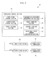
- Fig. 2 is a diagram showing a configuration relating to rotational speed control on the compressor 3 in the various functions that the device for controlling the air conditioner 10 has.
- the control device 20 includes, as its main components, a compressor control section 21, a lower-stage driver 22a for driving the lower-stage compressor 3a, and a higher-stage driver 22b for driving the higher-stage compressor 3b.
- Each of the lower-stage driver 22a and the higher-stage driver 22b includes, for example, an inverter having six switching elements, a gate driver for driving the switching elements constituting the inverter, and a microprocessor which supplies a PWM signal to the gate driver based on the rotational speed command from the compressor control section 21.
- the compressor control section 21 is, for example, a microprocessor. Various functions realized by sections in the compressor control section 21 described below are realized by a CPU reading out to a memory, such as a RAM, a program stored in a recording medium such as a ROM and executing the program.
- a memory such as a RAM
- a program stored in a recording medium such as a ROM
- the compressor control section 21 includes, for example, a lower-stage storage section (low-pressure-side storage means) 31, a higher-stage storage section (high-pressure-side storage means) 32, a target setting section (target setting means) 33, an intermediate-pressure determination section (intermediate pressure determination means) 34, a target changing section (target changing means) 35, a current limiting section 36 and a rotational speed command computation section 37.
- first information in which a rotational speed, an intermediate pressure, and an efficiency are associated with each other for the lower-stage compressor 3a is stored.
- a lower-stage efficiency table in which an intermediate pressure, and an efficiency are associated with each other as shown in Fig. 3 is stored on a rotational speed by rotational speed basis in the lower-stage storage section 31.
- second information in which a rotational speed, an intermediate pressure, and an efficiency are associated with each other for the higher-stage compressor 3b is stored.
- a higher-stage efficiency table in which an intermediate pressure, and an efficiency are associated with each other is stored on a rotational speed by rotational speed basis in the higher-stage storage section 32, as is that in the lower-stage storage section 31.
- the target setting section 33 sets a target intermediate pressure in accordance with a predetermined algorithm. For example, the target setting section 33 sets, from the evaporation pressure and the condensation pressure, a target intermediate pressure at an intermediate pressure at which the compression ratio of the lower-stage compressor 3a and the compression ratio of the higher-stage compressor 3b are equal to each other.
- the intermediate-pressure determination section 34 determines, from the rotational speed of the lower-stage compressor 3a, the rotational speed of the higher-stage compressor 3b, the first information and the second information, an intermediate pressure at which the overall efficiency of the compressor becomes equal to or higher than the present overall efficiency. For example, the intermediate-pressure determination section 34 extracts efficiencies ⁇ 1 and ⁇ 2 at the same pressure Pm_i from the lower-stage efficiency table corresponding to the present rotational speed of the lower-stage compressor 3a and the higher-stage efficiency table corresponding to the present rotational speed of the higher-stage compressor 3b, and computes the overall efficiency of the compressor 3 at the intermediate pressure Pm_i by substituting the efficiencies ⁇ 1 and ⁇ 2 in the following expression (1).
- ⁇ _all is the overall efficiency of the compressor 3;
- X is the rate of injection of the gas refrigerant, which is computed from the intermediate pressure (Pm_i) and the degree of subcooling;
- ⁇ 1 is the efficiency of the lower-stage compressor 3a at the intermediate pressure Pm_i;
- ⁇ 2 is the efficiency of the higher-stage compressor 3b at the intermediate pressure Pm_i.
- the above expression (1) is an expression derived from a process described below.
- Gr1 is the rate of circulating refrigerant through the lower-stage compressor
- Gr2 is the rate of circulating refrigerant through the higher-stage compressor
- h AB is the difference in enthalpy between A and B in Fig. 4
- h CD is the difference in enthalpy between C and D in Fig. 4
- X is the refrigerant dryness.
- the intermediate-pressure determination section 34 computes the overall efficiency ⁇ _all of the compressor 3 when the value of the intermediate pressure Pm_i is changed in a predetermined range of intermediate pressure, and determines an intermediate pressure at which the value of the overall efficiency ⁇ _all is maximized.
- the target changing section 35 changes the present target intermediate pressure to the intermediate pressure determined by the intermediate-pressure determination section 34.
- the current limiting section 36 controls a current (e.g., a motor current) flowing through the higher-stage driver 22b so as to stop the current from exceeding a predetermined current limit value determined from the configuration of the higher-stage driver 22b. For example, when the motor current exceeds the current limit value, the present target intermediate pressure is increased until the motor current becomes equal to or lower than the current limit value. Also, when in this state the motor current becomes equal to or lower than a release current value set in advance, the target intermediate pressure is changed to the theoretical intermediate pressure.
- a current e.g., a motor current
- the rotational speed command computation section 37 generates a lower-stage rotational speed command ⁇ a* to be supplied to the lower-stage driver 22a and a higher-stage rotational speed command ⁇ b* to be supplied to the higher-stage driver 22b.
- the rotational speed command computation section 37 generates, during cooling operation, a rotational speed command ⁇ a* for the lower-stage compressor 3a such that the low-level pressure (lower-stage compressor 3a drawing pressure) becomes equal to a target low-level pressure determined from a set indoor temperature, and generates, during heating operation, a rotational speed command ⁇ a* for the lower-stage compressor 3a such that, for example, the high-level pressure (higher-stage compressor 3b ejection pressure) becomes equal to a target high-level pressure determined from a set indoor temperature.
- the rotational speed command computation section 37 generates a rotational speed command ⁇ b* for the higher-stage compressor 3b such that the intermediate pressure coincides with the target intermediate pressure presently set.
- the rotational speed command computation section 37 may hold a rotational speed command ⁇ b* computation equation including a target intermediate pressure as a parameter and obtain a rotational speed command ⁇ b* by inputting the target intermediate pressure to the computation equation.
- the rotational speed command computation section 37 may alternatively hold a table in which a target intermediate pressure, and a rotational speed command ⁇ b* are associated with each other and obtain the rotational speed command ⁇ b* corresponding to the target intermediate pressure from this table. In such a case, when the target intermediate pressure is increased, the rotational speed of the higher-stage compressor 3b is controlled in the decreasing direction.
- the lower-stage rotational speed command ⁇ a* determined by the rotational speed command computation section 37 is supplied to the lower-stage driver 22a, and the higher-stage rotational speed command ⁇ b* is supplied to the higher-stage driver 22b.
- Each of the lower-stage driver 22a and the higher-stage driver 22b drives the inverter so that the rotational speed of the compressor motor coincides with the supplied lower-stage rotational speed command ⁇ a* or higher-stage rotational speed command ⁇ b*.
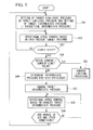
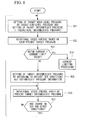
- Different kinds of target values are set on the basis of various sorts of input information, for example, information on cooling or heating, an outside air temperature and a set indoor temperature (step SA1).
- a target low-level pressure is set from a set indoor temperature.
- a target high-level pressure is set from a set indoor temperature.
- the theoretical intermediate pressure is set as a target intermediate pressure.
- rotational speed control on the lower-stage compressor 3a is performed on the basis of the target low-level pressure (in the case of cooling) or the target high-level pressure (in the case of heating) set in step SA1
- step SA3 determination is made as to whether or not the air conditioner is in a stable state. For example, determination as to whether or not the air conditioner is in a stable state is made by determining, when cooling is performed, whether the difference between the low-level pressure and the target low-level pressure is within an allowable range and whether the difference between the intermediate pressure, and the target intermediate pressure is within an allowable range, or by determining, when heating is performed, whether the difference between the high-level pressure and the target high-level pressure is within an allowable range and whether the difference between the intermediate pressure, and the target intermediate pressure is within an allowable range. Determination as to whether the air conditioner is in a stable state is not limited to the above-described example. For example, determination as to whether the air conditioner is in a stable state may be made by determining whether the difference between the indoor temperature and the set indoor temperature is within an allowable range.
- step SA3 If the result is that the air conditioner is not in a stable state ("NO” in step SA3), the process returns to step SA2 and rotational speed control is performed on the basis of each target pressure. If the air conditioner is in a stable state ("YES” in step SA3), determination is made as to whether or not the motor current has exceeded the predetermined current limit value (step SA4). If the motor current has exceeded the predetermined current limit value (“YES” in step SA4), current limiting processing is performed (step SA5). The target intermediate pressure set in step SA1 is thereby increased until the motor current becomes equal to or lower than the current limit value, and the rotational speed of the higher-stage compressor 3b is controlled on the basis of the target intermediate pressure at which the motor current becomes equal to or lower than the current limit value.
- step SA4 determines whether the motor current has not exceeded the predetermined current limit value ("NO" in step SA4). If it is determined in step SA4 that the motor current has not exceeded the predetermined current limit value ("NO" in step SA4), an intermediate pressure at which the overall efficiency ⁇ _all of the compressor 3 is maximized is determined by using the lower-stage efficiency table corresponding to the present rotational speed of the lower-stage compressor 3a, the higher-stage efficiency table corresponding to the present rotational speed of the higher-stage compressor 3b and expression (1) shown above (step SA6).
- the lower-stage rotational speed command ⁇ a* determined from the target high-level pressure or the target low-level pressure and the higher-stage rotational speed command ⁇ b* determined from the present intermediate pressure may be used in place of the actual rotational speed of the lower-stage compressor 3a and the actual rotational speed of the higher-stage compressor 3b.
- Use of the lower-stage rotational speed command ⁇ a* and the higher-stage rotational speed command ⁇ b* in this way enables removal of noise components and selection of a suitable one of the efficiency tables.
- step SA7 the present target intermediate pressure is changed to the intermediate pressure determined in step SA6 (step SA7) and rotational speed control on the higher-stage compressor 3b is performed on the basis of the changed target intermediate pressure (step SA8), thereby enabling the compressor 3 to be operated with improved efficiency in comparison with the case where the intermediate pressure is controlled at the theoretical intermediate pressure.
- step SA9 determination is made as to whether or not any one of the set and other conditions including the outside air temperature and the set indoor temperature has been changed. If none of the conditions has been changed, the process returns to step SA8 and rotational speed control is performed on the basis of the changed target intermediate pressure, i.e., the target intermediate pressure at which the overall efficiency of the compressor 3 is maximized. On the other hand, if one of the set and other conditions has been changed, the process returns to step SA1, a target high-level pressure or a target low-level pressure is newly set on the basis of the conditions after the change, and the target intermediate pressure is set to the theoretical intermediate pressure.
- a lower-stage efficiency table indicating an efficiency characteristic of the lower-stage compressor 3a and a higher-stage efficiency table indicating an efficiency characteristic of the higher-stage compressor 3b are respectively prepared; an intermediate pressure at which the efficiency of the compressor 3 as a whole is improved is determined by using information in the tables; and the rotational speed of the higher-stage compressor 3b is controlled on the basis of the determined intermediate pressure. Since an intermediate pressure at which the efficiency is maximized is determined by using the actual efficiency characteristics of the lower-stage compressor 3a and the higher-stage compressor 3b as described above, the efficiency (performance) can be improved in comparison with the case where rotational speed control is performed on the basis of the theoretical intermediate pressure.
- the intermediate-pressure determination section 34 determines an intermediate pressure at which the overall efficiency ⁇ _all of the compressor 3 is maximized. For example, if an intermediate pressure at which an overall efficiency higher than the overall efficiency ⁇ _all exhibited when control based on the theoretical intermediate pressure is performed is taken, the objective to improve the performance can be accomplished.
- the overall efficiency ⁇ _all when an intermediate pressure is changed is computed by using the lower-stage efficiency table and the higher-stage efficiency table, and the intermediate pressure at which the overall efficiency ⁇ _all is highest in the computation results is set as a target intermediate pressure.
- the intermediate pressure at which the efficiency is maximized can be determined from the outside air temperature, the set indoor temperature and the rotational speed of the low-pressure-side compressor without performing computation such as described above, for a reason described below.
- the higher-stage rotational speed command ⁇ b* is constantly maintained as long as the intermediate pressure is not changed, since the rotation speed of the higher-stage compressor 3b is controlled on the basis of the intermediate pressure.
- the rotational speed of the lower-stage compressor 3a is changed with a change in the set conditions. More specifically, the target high-level pressure or the target low-level pressure is changed in response to a change in outside air temperature or set indoor temperature. With this change in target high-level pressure or target low-level pressure, the rotational speed of the lower-stage compressor 3a is changed.
- the lower-stage efficiency table to be referred to at the time of computation of the intermediate pressure at which the overall efficiency of the compressor 3 is maximized is changed. Accordingly, a time when the intermediate pressure for improved efficiency is changed is said to be a time when the outside air temperature or the set indoor temperature is changed.
- intermediate pressure information in which the outside air temperature, the set indoor temperature, the rotational speed of the lower-stage compressor 3a and the intermediate pressure at which the overall efficiency of the compressor 3 is maximized are associated with each other may be prepared in advance to enable obtaining the intermediate pressure at which the overall efficiency ⁇ _all of the compressor 3 is maximized directly from the outside air temperature, the set indoor temperature and the rotational speed of the lower-stage compressor 3a.
- a control device 20' sets a target intermediate pressure by using the above-described intermediate pressure information.
- the air conditioner, and the device and method for controlling the air conditioner according to the present embodiment will be described mainly with respect to points of difference from the above-described first embodiment while omitting description of commonalities with the first embodiment.
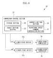
- Fig. 6 is a diagram showing the configuration of the control device 20' according to the present embodiment.
- a compressor control section 21' includes a storage section 30 provided in place of the lower-stage storage section 31 and the higher-stage storage section 32 according to the first embodiment shown in Fig. 2 , the storage section (storage means) 30 storing intermediate pressure information in which an outside air temperature, a set indoor temperature, the rotational speed of the lower-stage compressor 3a and an intermediate pressure at which the overall efficiency of the compressor 3 is maximized are associated with each other.
- the intermediate-pressure determination section 34 and the target changing section 35 are removed, and a target setting section (target setting means) 33' sets as a target intermediate pressure an intermediate pressure obtained from the intermediate pressure information stored in the storage section 30.
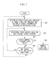
- different kinds of target values are set on the basis of various sorts of input information, for example, information on cooling or heating, an outside air temperature and a set indoor temperature (step SB1), as shown in Fig. 7 .
- input information for example, information on cooling or heating, an outside air temperature and a set indoor temperature (step SB1), as shown in Fig. 7 .
- a target low-level pressure is set from a set indoor temperature.
- a target high-level pressure is set from a set indoor temperature.
- an intermediate pressure corresponding to the present outside air temperature and set indoor temperature is obtained from the intermediate pressure information stored in the storage section 30 and is set as a target intermediate pressure.
- step SB3 determination is made as to whether or not the motor current has exceeded the predetermined current limit value. If the motor current has exceeded the predetermined current limit value ("YES" in step SB3), current limiting processing is performed (step SB4).
- the target intermediate pressure set in step SB1 is thereby increased until the motor current becomes equal to or lower than the current limit value, and the rotational speed of the higher-stage compressor 3b is controlled on the basis of the target intermediate pressure at which the motor current becomes equal to or lower than the current limit value.
- step SB3 determines whether or not any one of the set and other conditions including the outside air temperature and the set indoor temperature has been changed. If none of the conditions has been changed, the process returns to step SB2 and rotational speed control is performed on the basis of the present target intermediate pressure. On the other hand, if one of the set and other conditions has been changed, the process returns to step SB1, a target high-level pressure or a target low-level pressure is newly set on the basis of the conditions after the change, and the target intermediate pressure is set by using the intermediate pressure information in the storage section 30.
- the computation process can be simplified in comparison with the first embodiment and the computation processing load can be reduced.
- the target setting section 33' sets as a target intermediate pressure an intermediate pressure obtained by referring to the intermediate pressure information in step SB1 in Fig. 7 .
- the theoretical intermediate pressure is set as an initial value of a target intermediate pressure, and a target intermediate pressure setting using the intermediate pressure information is thereafter made as in the above-described second embodiment.
- a process executed by the control device 20' according to the present embodiment will be described below with reference to Fig. 8 .
- the configuration of the control device is generally the same as that of the control device 20' according to the second embodiment, and the description of the configuration of the control device is therefore omitted.
- target setting section 33' on the basis of various sorts of input information, for example, information on cooling or heating, an outside air temperature and a set indoor temperature as in the above-described first embodiment (step SC1).
- input information for example, information on cooling or heating, an outside air temperature and a set indoor temperature as in the above-described first embodiment (step SC1).
- a target low-level pressure is set from a set indoor temperature.
- a target high-level pressure is set from a set indoor temperature.
- the theoretical intermediate pressure is set as a target intermediate pressure.
- step SC3 determination is made as to whether or not the motor current has exceeded the predetermined current limit value. If the motor current has exceeded the predetermined current limit value ("YES" in step SC3), current limiting processing is performed (step SC4).
- the target intermediate pressure set in step SC1 is thereby increased until the motor current becomes equal to or lower than the current limit value, and the rotational speed of the higher-stage compressor 3b is controlled on the basis of the target intermediate pressure at which the motor current becomes equal to or lower than the current limit value.
- step SC3 determines whether the motor current has not exceeded the predetermined current limit value ("NO" in step SC3).
- the intermediate pressure corresponding to the present outside air temperature, the set indoor temperature and the rotational speed of the lower-stage compressor 3a is obtained by the target setting section 33' from the intermediate pressure information stored in the storage section 30 and is set as the target intermediate pressure (step SC5).
- Rotational speed control on the higher-stage compressor 3b is then performed on the basis of the changed target intermediate pressure (step SC6).
- the compressor 3 can be operated with improved efficiency in comparison with the case where the intermediate pressure is controlled at the theoretical intermediate pressure.
- step SC7 determination is made as to whether or not any one of the set and other conditions including the outside air temperature and the set indoor temperature has been changed. If none of the conditions has been changed, the process returns to step SC6 and rotational speed control is performed on the basis of the present target intermediate pressure, i.e., the target intermediate pressure at which the overall efficiency of the compressor 3 is maximized. On the other hand, if one of the set and other conditions has been changed, the process returns to step SC1 and the above-described processing is repeated.
Landscapes
- Engineering & Computer Science (AREA)
- Mechanical Engineering (AREA)
- General Engineering & Computer Science (AREA)
- Physics & Mathematics (AREA)
- Thermal Sciences (AREA)
- Air Conditioning Control Device (AREA)
- Control Of Positive-Displacement Pumps (AREA)
Applications Claiming Priority (1)
| Application Number | Priority Date | Filing Date | Title |
|---|---|---|---|
| JP2014225278A JP6545448B2 (ja) | 2014-11-05 | 2014-11-05 | 二段圧縮式冷凍サイクル装置及びその制御装置並びに制御方法 |
Publications (2)
| Publication Number | Publication Date |
|---|---|
| EP3018351A2 true EP3018351A2 (de) | 2016-05-11 |
| EP3018351A3 EP3018351A3 (de) | 2016-08-31 |
Family
ID=54540869
Family Applications (1)
| Application Number | Title | Priority Date | Filing Date |
|---|---|---|---|
| EP15193090.6A Withdrawn EP3018351A3 (de) | 2014-11-05 | 2015-11-05 | Kältekreislaufvorrichtung mit zweistufiger verdichtung sowie vorrichtung und verfahren zur steuerung der vorrichtung |
Country Status (2)
| Country | Link |
|---|---|
| EP (1) | EP3018351A3 (de) |
| JP (1) | JP6545448B2 (de) |
Cited By (4)
| Publication number | Priority date | Publication date | Assignee | Title |
|---|---|---|---|---|
| EP3453986A4 (de) * | 2016-08-05 | 2019-06-12 | Mitsubishi Heavy Industries Thermal Systems, Ltd. | Heizpumpvorrichtung und steuerungsverfahren dafür |
| CN112815571A (zh) * | 2021-01-18 | 2021-05-18 | 中科广能能源研究院(重庆)有限公司 | 燃气热泵发动机驱动压缩机的转速调节控制方法及系统 |
| CN114413497A (zh) * | 2022-01-06 | 2022-04-29 | 珠海格力电器股份有限公司 | 双级压缩机及控制方法、装置以及控制设备、制冷设备 |
| WO2023194477A1 (de) * | 2022-04-07 | 2023-10-12 | Efficient Energy Gmbh | Wärmepumpe |
Families Citing this family (1)
| Publication number | Priority date | Publication date | Assignee | Title |
|---|---|---|---|---|
| CN112361685B (zh) * | 2020-12-14 | 2021-09-17 | 珠海格力电器股份有限公司 | 双级压缩机控制方法、双级压缩机制冷系统及制冷设备 |
Citations (2)
| Publication number | Priority date | Publication date | Assignee | Title |
|---|---|---|---|---|
| JP2013120024A (ja) * | 2011-12-08 | 2013-06-17 | Samsung Yokohama Research Institute Co Ltd | ヒートポンプ |
| JP2014016079A (ja) | 2012-07-06 | 2014-01-30 | Daikin Ind Ltd | ヒートポンプ |
Family Cites Families (5)
| Publication number | Priority date | Publication date | Assignee | Title |
|---|---|---|---|---|
| BE1012944A3 (nl) * | 1999-10-26 | 2001-06-05 | Atlas Copco Airpower Nv | Meertraps-compressoreenheid en werkwijze voor het regelen van een der gelijke meertraps-compressoreenheid. |
| GB2367332B (en) * | 2000-09-25 | 2003-12-03 | Compair Uk Ltd | Improvements in multi-stage screw compressor drive arrangements |
| JP5372880B2 (ja) * | 2010-09-22 | 2013-12-18 | 株式会社神戸製鋼所 | 2段圧縮冷凍装置 |
| JP6010294B2 (ja) * | 2011-12-06 | 2016-10-19 | 株式会社サムスン日本研究所 | 空気調和機 |
| JP6656801B2 (ja) * | 2014-11-05 | 2020-03-04 | 三菱重工サーマルシステムズ株式会社 | 二段圧縮式冷凍サイクル装置及びその制御装置並びに制御方法 |
-
2014
- 2014-11-05 JP JP2014225278A patent/JP6545448B2/ja active Active
-
2015
- 2015-11-05 EP EP15193090.6A patent/EP3018351A3/de not_active Withdrawn
Patent Citations (2)
| Publication number | Priority date | Publication date | Assignee | Title |
|---|---|---|---|---|
| JP2013120024A (ja) * | 2011-12-08 | 2013-06-17 | Samsung Yokohama Research Institute Co Ltd | ヒートポンプ |
| JP2014016079A (ja) | 2012-07-06 | 2014-01-30 | Daikin Ind Ltd | ヒートポンプ |
Cited By (5)
| Publication number | Priority date | Publication date | Assignee | Title |
|---|---|---|---|---|
| EP3453986A4 (de) * | 2016-08-05 | 2019-06-12 | Mitsubishi Heavy Industries Thermal Systems, Ltd. | Heizpumpvorrichtung und steuerungsverfahren dafür |
| CN112815571A (zh) * | 2021-01-18 | 2021-05-18 | 中科广能能源研究院(重庆)有限公司 | 燃气热泵发动机驱动压缩机的转速调节控制方法及系统 |
| CN112815571B (zh) * | 2021-01-18 | 2022-10-28 | 中科广能能源研究院(重庆)有限公司 | 燃气热泵发动机驱动压缩机的转速调节控制方法及系统 |
| CN114413497A (zh) * | 2022-01-06 | 2022-04-29 | 珠海格力电器股份有限公司 | 双级压缩机及控制方法、装置以及控制设备、制冷设备 |
| WO2023194477A1 (de) * | 2022-04-07 | 2023-10-12 | Efficient Energy Gmbh | Wärmepumpe |
Also Published As
| Publication number | Publication date |
|---|---|
| JP6545448B2 (ja) | 2019-07-17 |
| EP3018351A3 (de) | 2016-08-31 |
| JP2016090143A (ja) | 2016-05-23 |
Similar Documents
| Publication | Publication Date | Title |
|---|---|---|
| JP5984703B2 (ja) | 熱源システム及び冷却水供給装置の制御装置並びに制御方法 | |
| EP2933588B1 (de) | Kombinationssystem für klimatisierung und heisswasserversorgung | |
| EP2821725B1 (de) | Wärmequellensystem mit einer vorrichtung zur maschinenanzahlsteuerung, verfahren dafür | |
| EP2693136A1 (de) | Expansionsventil-steuervorrichtung, wärmequellenmaschine und expansionsventil-steuerverfahren | |
| US20090126381A1 (en) | Trigeneration system and method | |
| EP3018351A2 (de) | Kältekreislaufvorrichtung mit zweistufiger verdichtung sowie vorrichtung und verfahren zur steuerung der vorrichtung | |
| EP2792973A1 (de) | Klimaanlage und Steuerverfahren dafür | |
| JP2014016079A (ja) | ヒートポンプ | |
| US9341401B2 (en) | Heat source system and control method therefor | |
| EP3026370A1 (de) | Kältekreislaufvorrichtung mit zweistufiger verdichtung sowie vorrichtung und verfahren zur steuerung der vorrichtung | |
| JP6698312B2 (ja) | 制御装置、制御方法、及び熱源システム | |
| JP2008292122A (ja) | 蓄熱システム及びこれを用いた蓄熱式空気調和装置 | |
| JP6987598B2 (ja) | 冷凍サイクルの制御装置、熱源装置、及びその制御方法 | |
| US20170356681A1 (en) | Refrigeration and heating system | |
| JP2020079688A (ja) | ターボ冷凍機 | |
| JP2017122556A (ja) | 二段圧縮式冷凍サイクル装置、その制御装置及び制御方法並びに制御プログラム | |
| JP2013217602A (ja) | 熱源機、冷凍空調装置、制御装置 | |
| JP2007187332A (ja) | 冷凍サイクル装置 | |
| JP2017172857A (ja) | 熱源システムの設定温度制御装置、及びそれを備えた熱源システム、並びに熱源システムの設定温度制御方法 |
Legal Events
| Date | Code | Title | Description |
|---|---|---|---|
| PUAI | Public reference made under article 153(3) epc to a published international application that has entered the european phase |
Free format text: ORIGINAL CODE: 0009012 |
|
| AK | Designated contracting states |
Kind code of ref document: A2 Designated state(s): AL AT BE BG CH CY CZ DE DK EE ES FI FR GB GR HR HU IE IS IT LI LT LU LV MC MK MT NL NO PL PT RO RS SE SI SK SM TR |
|
| AX | Request for extension of the european patent |
Extension state: BA ME |
|
| PUAL | Search report despatched |
Free format text: ORIGINAL CODE: 0009013 |
|
| RIC1 | Information provided on ipc code assigned before grant |
Ipc: F04C 28/02 20060101ALI20160705BHEP Ipc: F04C 23/00 20060101AFI20160705BHEP |
|
| RIC1 | Information provided on ipc code assigned before grant |
Ipc: F04C 28/02 20060101ALI20160721BHEP Ipc: F04C 23/00 20060101AFI20160721BHEP |
|
| AK | Designated contracting states |
Kind code of ref document: A3 Designated state(s): AL AT BE BG CH CY CZ DE DK EE ES FI FR GB GR HR HU IE IS IT LI LT LU LV MC MK MT NL NO PL PT RO RS SE SI SK SM TR |
|
| AX | Request for extension of the european patent |
Extension state: BA ME |
|
| STAA | Information on the status of an ep patent application or granted ep patent |
Free format text: STATUS: REQUEST FOR EXAMINATION WAS MADE |
|
| 17P | Request for examination filed |
Effective date: 20170227 |
|
| RBV | Designated contracting states (corrected) |
Designated state(s): AL AT BE BG CH CY CZ DE DK EE ES FI FR GB GR HR HU IE IS IT LI LT LU LV MC MK MT NL NO PL PT RO RS SE SI SK SM TR |
|
| STAA | Information on the status of an ep patent application or granted ep patent |
Free format text: STATUS: EXAMINATION IS IN PROGRESS |
|
| 17Q | First examination report despatched |
Effective date: 20181122 |
|
| STAA | Information on the status of an ep patent application or granted ep patent |
Free format text: STATUS: THE APPLICATION IS DEEMED TO BE WITHDRAWN |
|
| 18D | Application deemed to be withdrawn |
Effective date: 20200603 |