EP3018385B1 - Kugelschraube - Google Patents
Kugelschraube Download PDFInfo
- Publication number
- EP3018385B1 EP3018385B1 EP14846270.8A EP14846270A EP3018385B1 EP 3018385 B1 EP3018385 B1 EP 3018385B1 EP 14846270 A EP14846270 A EP 14846270A EP 3018385 B1 EP3018385 B1 EP 3018385B1
- Authority
- EP
- European Patent Office
- Prior art keywords
- nut
- protruding portion
- spiral groove
- raceway
- piece
- Prior art date
- Legal status (The legal status is an assumption and is not a legal conclusion. Google has not performed a legal analysis and makes no representation as to the accuracy of the status listed.)
- Active
Links
Images


Classifications
-
- F—MECHANICAL ENGINEERING; LIGHTING; HEATING; WEAPONS; BLASTING
- F16—ENGINEERING ELEMENTS AND UNITS; GENERAL MEASURES FOR PRODUCING AND MAINTAINING EFFECTIVE FUNCTIONING OF MACHINES OR INSTALLATIONS; THERMAL INSULATION IN GENERAL
- F16H—GEARING
- F16H25/00—Gearings comprising primarily only cams, cam-followers and screw-and-nut mechanisms
- F16H25/18—Gearings comprising primarily only cams, cam-followers and screw-and-nut mechanisms for conveying or interconverting oscillating or reciprocating motions
- F16H25/20—Screw mechanisms
- F16H25/22—Screw mechanisms with balls, rollers, or similar members between the co-operating parts; Elements essential to the use of such members
-
- F—MECHANICAL ENGINEERING; LIGHTING; HEATING; WEAPONS; BLASTING
- F16—ENGINEERING ELEMENTS AND UNITS; GENERAL MEASURES FOR PRODUCING AND MAINTAINING EFFECTIVE FUNCTIONING OF MACHINES OR INSTALLATIONS; THERMAL INSULATION IN GENERAL
- F16H—GEARING
- F16H25/00—Gearings comprising primarily only cams, cam-followers and screw-and-nut mechanisms
- F16H25/18—Gearings comprising primarily only cams, cam-followers and screw-and-nut mechanisms for conveying or interconverting oscillating or reciprocating motions
- F16H25/20—Screw mechanisms
- F16H25/22—Screw mechanisms with balls, rollers, or similar members between the co-operating parts; Elements essential to the use of such members
- F16H25/2204—Screw mechanisms with balls, rollers, or similar members between the co-operating parts; Elements essential to the use of such members with balls
- F16H25/2214—Screw mechanisms with balls, rollers, or similar members between the co-operating parts; Elements essential to the use of such members with balls with elements for guiding the circulating balls
- F16H25/2223—Cross over deflectors between adjacent thread turns, e.g. S-form deflectors connecting neighbouring threads
-
- F—MECHANICAL ENGINEERING; LIGHTING; HEATING; WEAPONS; BLASTING
- F16—ENGINEERING ELEMENTS AND UNITS; GENERAL MEASURES FOR PRODUCING AND MAINTAINING EFFECTIVE FUNCTIONING OF MACHINES OR INSTALLATIONS; THERMAL INSULATION IN GENERAL
- F16H—GEARING
- F16H25/00—Gearings comprising primarily only cams, cam-followers and screw-and-nut mechanisms
- F16H25/18—Gearings comprising primarily only cams, cam-followers and screw-and-nut mechanisms for conveying or interconverting oscillating or reciprocating motions
- F16H25/20—Screw mechanisms
- F16H25/24—Elements essential to such mechanisms, e.g. screws, nuts
-
- F—MECHANICAL ENGINEERING; LIGHTING; HEATING; WEAPONS; BLASTING
- F16—ENGINEERING ELEMENTS AND UNITS; GENERAL MEASURES FOR PRODUCING AND MAINTAINING EFFECTIVE FUNCTIONING OF MACHINES OR INSTALLATIONS; THERMAL INSULATION IN GENERAL
- F16H—GEARING
- F16H25/00—Gearings comprising primarily only cams, cam-followers and screw-and-nut mechanisms
- F16H25/18—Gearings comprising primarily only cams, cam-followers and screw-and-nut mechanisms for conveying or interconverting oscillating or reciprocating motions
- F16H25/20—Screw mechanisms
- F16H25/24—Elements essential to such mechanisms, e.g. screws, nuts
- F16H2025/249—Materials or coatings for screws or nuts
Definitions
- the present invention relates to a ball screw.
- Ball screws are devices including a nut having a spiral groove formed in an inner peripheral surface, a screw shaft having a spiral groove formed in an outer peripheral surface, balls arranged between a raceway formed by the spiral groove of the nut and the spiral groove of the screw shaft; and a ball return passage for returning the balls from an end point of the raceway to a start point.
- the ball screw is configured such that via the balls that roll within the raceway, the nut moves relatively to the screw shaft and coverts a linear motion into a rotational motion or converts a rotational motion into a linear motion.
- Such ball screws are used not only for positioning devices or the like of general industrial machines but also for electric actuators mounted on vehicles, such as automobiles, two-wheeled vehicles, and ships. Such electric actuators are demanded to be low in vibration and small in noise.
- PTL 1 discloses a linear motion actuator including a rotational motion element and a linear motion element, and a ball screw mechanism that converts a rotational motion transmitted to the rotational motion element into a linear motion.
- the ball screw mechanism has a guide protrusion that is provided in the linear motion element and protrudes in a radial direction, and a guide groove that guides the guide protrusion.
- the guide groove is arranged at a fixing portion facing the linear motion element so as to engage with the guide protrusion to guide the guide protrusion in an axial direction.
- the detent of the linear motion element is performed by the engagement between the guide groove and the guide protrusion.
- the axial length of the guide protrusion is set to a length capable of protruding from the guide groove by a predetermined length while engaging with the guide groove.
- a locking portion capable of locking the guide protrusion to the rotational motion element is provided.
- the guide protrusion protrudes from the guide groove by a predetermined length while engaging with the guide groove, and a protruding portion of the guide protrusion is locked to the locking portion. That is, the guide protrusion has not only the detent function of the linear motion element but also the stopper function for the rotational motion element.
- PTL 1 discloses an example of a nut in which the rotational motion element constitutes the ball screw mechanism and which has a columnar body protruding from an axial end surface as the locking portion.
- the shape of the nut of the ball screw is not a simple cylindrical member as in this example, the center of gravity of the nut deviates from the rotational center line of the nut. If the center of gravity of the nut deviates from the rotational center line of the nut, the nut rotates unevenly when the ball screw is driven. Along with this, a load applied to the balls that roll within a raceway becomes uneven. As a result, since the circulation of the balls becomes uneven, vibration is generated in the ball screw.
- the return tube is attached to a flat surface provided on the outer peripheral surface of the nut. Therefore, the center of gravity of the nut deviates from the rotational center line of the nut.
- PTL 2 discloses that the center of gravity of a nut is brought close to a rotational center line of a nut by forming the shape of the nut in a shape in which a flat portion (attachment seat) for attaching a return tube, and plural thinning machined portions (cut-off portions of an outer peripheral portion) are provided at a cylindrical member or by providing the attachment seat with a weight member.
- the piece in which a recessed portion that forms the ball return passage is formed is fitted into a through-hole that is provided in the nut and extends in the radial direction of the nut.
- the piece allows a start point and an end point of a raceway equivalent to one circulation of the ball screw to communicate with each other and allows a ball at the end point of the ball screw to ride over the screw thread (land portion) of the spiral groove to return the ball to the start point.
- plural pieces are arranged at equal intervals in the circumferential direction of the nut.
- the nut has a protruding portion that protrudes from the axial end surface in one place in the circumferential direction. As a result, there is a problem that the nut rotates unevenly when the ball screw is driven, and vibration is generated.
- the thickness of the nut becomes small due to the thinning machined portions. Therefore, the strength needed for the nut may not be ensured. If the strength of the nut is ensured by thickening the thinning machined portions, portions other than the thinning machined portions become excessively thick. As a result, there are concerns about enlargement of the entire nut and an increase in the weight of the nut. Besides, the manufacturing cost of the nut is increased by forming the thinning machined portions.
- An object of the present invention is to bring the center of gravity of a nut close to a rotational center line of the nut without forming a thinning machined portion in the nut, in a ball screw including the nut having a protruding portion protruding from an axial end surface in a portion in a circumferential direction.
- the ball screw has the following configurations (a) to (d).
- a portion of the nut in which the recessed portion is formed is lighter than the other portions of the nut, and a portion of the nut in which the protruding portion is formed is heavier than the other portions of the nut.
- the deviation of the center of gravity of the nut from the rotational center line caused by the protruding portion is made small by appropriately combining a light portion resulting from the recessed portion with a heavy portion resulting from the protruding portion.
- the recessed portion is formed by a piece being fitted into a through-hole passing through the nut in a radial direction, and may be formed in an inner peripheral surface of a cylindrical nut material by a forging process.
- the ball screw of an embodiment has the following configuration (e). Accordingly, the deviation of the center of gravity of the nut from the rotational center line caused by the protruding portion is able to be made small by the configuration of the recessed portion.
- the nut includes two recessed portions arranged at the positions where central angles with the protruding portion being as a reference become 90 degrees or less in a circumferential direction of the nut.
- the piece when the recessed portion may be formed by the piece being fitted into the through-hole passing through the nut in the radial direction, the piece may be made of synthetic resin. This is because, generally, the nut is made of metal, and the protruding portion is made of metal because of being integrated with the nut. Therefore, if the piece is made of metal when the protruding portion is large or when the piece is large, sufficient effects may not be obtained.
- Synthetic resins that form the piece include polyphenylene sulfide (PPS), polyacetal (POM), and the like. Additionally, the piece may be manufactured using resin compositions in which a reinforcing material consisting of glass fibers, potassium titanate fibers, or the like is mixed with these synthetic resins.
- the ball screw may have one of the following configurations (f) to (g).
- the nut includes at least three pieces, all the pieces have the same dimensions and may be arranged at equal intervals in a circumferential direction of the nut, and a first one of the pieces may be arranged at the position same as the position of the protruding portion in the circumferential direction of the nut and is made of a material with a specific gravity smaller than the specific gravities of the other pieces.
- a piece made of synthetic resin is able to be used as the first piece made of the material with a smaller specific gravity
- a metallic piece is able to be used as the other pieces.
- a piece formed by a metal powder injection molding method (MIM) is able to be used.
- An alloy for the MIM to be used includes, for example, Fe-Ni-C (1 to 8% Ni and 0.8% C).
- the nut includes at least three pieces, all the pieces may be arranged at equal intervals in a circumferential direction of the nut, and a first one of the pieces may be arranged at the position same as the position of the protruding portion in the circumferential direction of the nut, and has dimensions smaller than the dimensions of the other pieces.
- the method for forming the above configurations (e) to (g) does not increase the manufacturing cost of the nut unlike the method of PTL 2 that forms a thinning machined portion in the nut.
- the ball screw in the present invention is able to be used for a wide range of applications, such as in automobile parts, outboard motors, and positioning devices, and particularly, is able to be suitably used for actuators for brakes of automobiles.
- the center of gravity of the nut can be brought close to the rotational center line of the nut without forming a thinning machined portion in the nut.
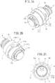
- a ball screw of this embodiment has a nut 1, a screw shaft 2, and a single piece 3.
- the nut 1 has a cylindrical portion 11, a flange portion 12 formed at the center of the cylindrical portion 11 in an axial direction, and a protruding portion 13 that protrudes from one end surface in the axial direction.
- the cylindrical portion 11 is divided into a first portion 11a in which the protruding portion 13 is formed in the axial direction of the nut 1, and a second portion 11b excluding the first portion, by the flange portion 12.
- a peripheral groove 14 is formed at the boundary of the first portion 11a between the first portion 11a and the flange portion 12.
- a through-hole 15 passing through the nut 1 in a radial direction is a portion including the peripheral groove 14 of the first portion 11a in the axial direction, and is formed at the same position as the protruding portion 13 in a circumferential direction.
- An inner peripheral surface of the cylindrical portion 11 has a spiral groove 110.
- An outer peripheral surface of the screw shaft 2 is formed with a spiral groove 21.
- Plural balls are arranged between raceways formed by the spiral groove 110 of the nut 1 and the spiral groove 21 of the screw shaft 2.
- the piece 3 has an elongated small piece shape, both ends of the piece in a longitudinal direction are formed in a substantially semicircular arc shape, a recessed portion along the longitudinal direction that forms a ball return passage is formed in one surface of the piece, and the other surface of the piece becomes a circumferential surface concentric with the cylindrical portion 11.
- the piece 3 is obtained by an injection molding method using PPS.
- the piece 3 is fitted to the through-hole 15 of the nut 1 such that a recessed portion side is directed to the screw shaft 2 side. Accordingly, the piece 3 is arranged at the same position as the protruding portion 13 in the circumferential direction of the nut 1, and the inner peripheral surface of the nut 1 is formed with the ball return passage consisting of the recessed portion of the piece 3.
- the protruding portion 13 is made of steel and is formed integrally with the cylindrical portion 10. That is, the shape of the nut 1 is given by cutting a cylindrical material made of a steel material. A portion of the nut 1 in which the piece 3 is fitted to the through-hole 15 is lighter than the other portions of the nut 1, and a portion of the nut 1 in which the protruding portion 13 is formed is heavier than the other portions of the nut 1.
- the deviation of the center of gravity of the nut 1 from a rotational center line caused by the protruding portion 13 is eliminated or is made small by the recessed portion of the piece 3 being arranged at the same position as the protruding portion 13 in the circumferential direction of the nut 1 (that is, the configuration of the recessed portion that constitutes the ball return passage).
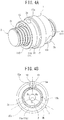
- a ball screw of this embodiment has the nut 1, the screw shaft 2, and two pieces 3.
- the nut 1 has the cylindrical portion 11, the flange portion 12 formed at the center of the cylindrical portion 11 in the axial direction, and the protruding portion 13 that protrudes from one end surface in the axial direction.
- the cylindrical portion 11 is divided into the first portion 11a in which the protruding portion 13 is formed in the axial direction of the nut 1, and the second portion 11b excluding the first portion, by the flange portion 12.
- the nut 1 has two through-holes 15a and 15b passing through the nut 1 in the radial direction.
- One through-hole 15a is the portion of the first portion 11a including the flange portion 12 in the axial direction, and is formed at a position where a central angle ⁇ 1 based on the protruding portion 13 in the circumferential direction becomes 57 degrees.
- the other through-hole 15b is the portion of the second portion 11b including the flange portion 12 in the axial direction, and is formed at a position where a central angle ⁇ 2 based on the protruding portion 13 in the circumferential direction becomes 57 degrees.
- the inner peripheral surface of the cylindrical portion 11 is formed with the spiral groove 110.
- the outer peripheral surface of the screw shaft 2 is formed with the spiral groove 21.
- the plurality of balls is arranged between the raceways formed by the spiral groove 110 of the nut 1 and the spiral groove 21 of the screw shaft 2.
- the two pieces 3 are the same and have an elongated small piece shape, both ends of each piece in a longitudinal direction are formed in a substantially semicircular arc shape, a recessed portion along the longitudinal direction that forms a ball return passage is formed in one surface of the piece, and the other surface of the piece becomes a circumferential surface concentric with the cylindrical portion 11.
- the pieces 3 are manufactured by a metal powder injection molding method using Fe-Ni-C (1 to 8% Ni and 0.8% C).
- the pieces 3 are fitted to the through-holes 15a and 15b of the nut 1 such that recessed portion sides are directed to the screw shaft 2 side.
- the two pieces 3 are arranged at positions where central angles ⁇ 1 and ⁇ 2 based on the protruding portion 13 in the circumferential direction of a nut 1 become 57 degrees, respectively, and the inner peripheral surface of the nut 1 is formed with two ball return passages consisting of the recessed portions of the respective pieces 3.
- the protruding portion 13 is made of steel and is formed integrally with the cylindrical portion 10. That is, the shape of the nut 1 is given by cutting a cylindrical material made of a steel material. Portions of the nut 1 in which the pieces 3 are fitted to the through-holes 15a and 15b are lighter than the other portions of the nut 1, and a portion of the nut 1 in which the protruding portion 13 is formed is heavier than the other portions of the nut 1.
- the deviation of the center of gravity of the nut 1 from the rotational center line caused by the protruding portion 13 is eliminated or is made small by the recessed portions of the pieces 3 being arranged at positions where the central angles based on the protruding portion 13 in the circumferential direction of the nut 1 become equal to or lower than 90 degrees (that is, the configuration of the recessed portions that constitute the ball return passages).
- a ball screw of this embodiment has the nut 1, the screw shaft 2, and three pieces 3a to 3c.
- the nut 1 has the cylindrical portion 11, the flange portion 12 formed at the center of the cylindrical portion 11 in the axial direction, and the protruding portion 13 that protrudes from one end surface in the axial direction.
- the cylindrical portion 11 is divided into the first portion 11a in which the protruding portion 13 is formed in the axial direction of the nut 1, and the second portion 11b excluding the first portion, by the flange portion 12.
- the peripheral groove 14 is formed at the boundary of the first portion 11a between the first portion 11a and the flange portion 12.
- the nut 1 is formed with three through-holes 15a to 15c passing through the nut in the radial direction.
- a first through-hole 15a is a portion including the peripheral groove 14 of the first portion 11a in the axial direction, and is formed at the same position as the protruding portion 13 in the circumferential direction.
- a second through-hole 15b is formed in the second portion 11b in the axial direction.
- a third through-hole 15c is formed in the second portion 11b in the axial direction.
- the three pieces 3 have an elongated small piece shape, both ends of each piece in a longitudinal direction are formed in a substantially semicircular arc shape, a recessed portion along the longitudinal direction that forms a ball return passage is formed in one surface of the piece, and the other surface of the piece becomes a circumferential surface concentric with the cylindrical portion 11.
- the first piece 3a is obtained by an injection molding method using PPS
- the second piece 3b and the third piece 3c are manufactured by a metal powder injection molding method using Fe-Ni-C (1 to 8% Ni and 0.8% C).
- the pieces 3a to 3c are respectively fitted to the through-holes 15a to 15c of the nut 1 such that recessed portion sides are directed to the screw shaft 2 side.
- the protruding portion 13 is made of steel and is formed integrally with the cylindrical portion 10. That is, the shape of the nut 1 is given by cutting a cylindrical material made of a steel material. Portions of the nut 1 in which the pieces 3a to 3c are fitted to the through-holes 15a to 15c are lighter than the other portions of the nut 1, and a portion of the nut 1 in which the protruding portion 13 is formed is heavier than the other portions of the nut 1.
- the nut 1 has the three pieces 3a to 3c, all the pieces 3a to 3c have the same dimensions and are arranged at equal intervals in the circumferential direction of the nut 1, the first piece 3a is arranged at the same position as the protruding portion 13 in the circumferential direction of the nut 1, and the deviation of the center of gravity of the nut 1 from the rotational center line caused by the protruding portion 13 is eliminated or is made small by the first piece 3a being made of a material with a smaller specific gravity than the second piece 3b and the third piece 3c (that is, the configuration of the recessed portions that constitute the ball return passages).
- the first piece 3a using a material with a smaller specific gravity than the second piece 3b and the third piece 3c, even if all the pieces 3a to 3c are made to have the same dimensions, all the pieces 3a to 3c are able to be arranged at equal intervals in the circumferential direction of the nut 1. Therefore, the distribution of load in the axial direction of the ball screw is able to be made uniform.
- a ball screw of this embodiment has the nut 1, the screw shaft 2, and the three pieces 3a to 3c.
- the nut 1 has the cylindrical portion 11, the flange portion 12 formed at the center of the cylindrical portion 11 in the axial direction, and the protruding portion 13 that protrudes from one end surface in the axial direction.
- the cylindrical portion 11 is divided into the first portion 11a in which the protruding portion 13 is formed in the axial direction of the nut 1, and the second portion 11b excluding the first portion, by the flange portion 12.
- the peripheral groove 14 is formed at the boundary of the first portion 11a between the first portion 11a and the flange portion 12.
- the nut 1 is formed with the three through-holes 15a to 15c passing through the nut in the radial direction.
- the first through-hole 15a is a portion including the peripheral groove 14 of the first portion 11a in the axial direction, and is formed at the same position as the protruding portion 13 in the circumferential direction.
- the second through-hole 15b is formed in the second portion 11b in the axial direction.
- the third through-hole 15c is formed in the second portion 11b in the axial direction.
- the second through-hole 15b and the third through-hole 15c have the same dimensions, and the dimensions of the first through-hole 15a are smaller than those of the second through-hole 15b and the third through-hole 15c.
- the three pieces 3 have an elongated small piece shape, both ends of each piece in a longitudinal direction are formed in a substantially semicircular arc shape, a recessed portion along the longitudinal direction that forms a ball return passage is formed in one surface of the piece, and the other surface of the piece becomes a circumferential surface concentric with the cylindrical portion 11.
- the three pieces 3 are manufactured by a metal powder injection molding method using the same Fe-Ni-C (1 to 8% Ni and 0.8% C).
- the second piece 3b and the third piece 3c have the same dimensions, and the dimensions of the first piece 3a are smaller than the dimensions of the second piece 3b and the third piece 3c.
- the protruding portion 13 is made of steel and is formed integrally with the cylindrical portion 10. That is, the shape of the nut 1 is given by cutting a cylindrical material made of a steel material. Portions of the nut 1 in which the pieces 3a to 3c are fitted to the through-holes 15a to 15c are lighter than the other portions of the nut 1, and a portion of the nut 1 in which the protruding portion 13 is formed is heavier than the other portions of the nut 1.
- the nut 1 has the three pieces 3a to 3c, all the pieces 3a to 3c are arranged at equal intervals in the circumferential direction of the nut 1, the first piece 3a is arranged at the same position as the protruding portion 13 in the circumferential direction of the nut 1, and the deviation of the center of gravity of the nut 1 from the rotational center line caused by the protruding portion 13 is eliminated or is made small by the first piece 3a having smaller dimensions than the second piece 3b and the third piece 3c (that is, the configuration of the recessed portions that constitute the ball return passages).
- all the pieces 3a to 3c are able to be arranged at equal intervals in the circumferential direction of the nut 1 while all the pieces 3a to 3c are made of the same material. Therefore, the distribution of load in the axial direction of the ball screw is able to be made uniform.
- the deviation of the center of gravity of the nut 1 from the rotational center line caused by the protruding portion 13 is not eliminated if all the pieces 3a to 3c are formed of the same material, the deviation is also able to be eliminated by forming the first piece 3a using a material with a smaller specific gravity than the second piece 3b and third piece 3c.
- the present invention relates to the ball screw which has the protruding portion protruding from the axial end surface, in which the center of gravity of the nut deviates from the rotational center line of the nut.
- the center of gravity of the nut deviates from the rotational center line of the nut.
- the deviation of the center of gravity of the nut from the rotational center line is able to be made small also by forming the recessed portion, which constitutes the ball return passage formed in the inner peripheral surface of the nut, at a suitable position outside of the formation position of the groove.
- the axial end of the spiral groove formed in the inner peripheral surface of the nut is an incomplete threaded portion, and the presence of the incomplete threaded portion becomes a cause by which the center of gravity of the nut deviates from the rotational center line of the nut.
- the deviation of the center of gravity of the nut from the rotational center line is able to be made small also by forming the recessed portion, which constitutes the ball return passage formed in the inner peripheral surface of the nut, at a position outside of the incomplete threaded portion.
Landscapes
- Engineering & Computer Science (AREA)
- General Engineering & Computer Science (AREA)
- Mechanical Engineering (AREA)
- Transmission Devices (AREA)
Claims (3)
- Kugelspindel, umfassend:eine Mutter (1) mit einer Spiralnut (110), die an einer inneren Umfangsfläche ausgebildet ist;eine Schneckenwelle (2) mit einer Spiralnut (21), die an einer äußeren Umfangsfläche ausgebildet ist;Kugeln, die zwischen einer Laufbahn angeordnet sind, die durch die Spiralnut (110) der Mutter (1) und die Spiralnut (21) der Schneckenwelle (2) gebildet wird; undeinen Kugelrückführungskanal, der konfiguriert ist, um die Kugeln von einem Endpunkt der Laufbahn zu einem Startpunkt der Laufbahn zurückzubringen;wobei die Kugeln innerhalb der Laufbahn rollen und sich die Schneckenwelle (2) in axialer Richtung bewegt, wenn sich die Mutter (1) dreht,wobei die Mutter (1) einen zylindrischen Abschnitt (11), einen Flanschabschnitt (12), der in einer Mitte des zylindrischen Abschnitts (11) ausgebildet ist, und einen hervorstehenden Abschnitt (13) umfasst, der so konfiguriert ist, dass er aus einer axialen Endfläche hervorsteht, wobei der hervorstehende Abschnitt (13) an einem Teil der Mutter (1) in Umfangsrichtung angeordnet ist,wobei der Kugelrückführungskanal ein vertiefter Abschnitt ist, der an der inneren Umfangsfläche der Mutter (1) ausgebildet ist, undwobei ein Gravitationszentrum der Mutter (1) aufgrund des hervorstehenden Abschnitts (13) von einer Rotationsmittellinie abweicht und die Abweichung durch den vertieften Abschnitt kleiner gemacht wird;dadurch gekennzeichnet, dassdie Mutter (1) zwei vertiefte Abschnitte enthält undwobei die zwei vertieften Abschnitte an den Positionen angeordnet sind, an denen zentrale Winkel mit dem hervorstehenden Abschnitt (13), der als Referenz dient, in Umfangsrichtung der Mutter (1) 90 Grad oder weniger betragen;und dass die Mutter (1) und der hervorstehende Abschnitt (13) aus Metall bestehen,wobei jeder vertiefte Abschnitt durch ein Teil (3) gebildet wird, das in radialer Richtung in ein Durchgangsloch (15) eingepasst ist, das durch die Mutter (1) in einer Radialrichtung verläuft, wobei das Teil (3) aus Kunstharz besteht;wobei das Durchgangsloch (15) an einer Position ausgebildet ist, die den Flanschabschnitt (12) in axialer Richtung enthält.
- Kugelspindel, umfassend:eine Mutter (1) mit einer Spiralnut (110), die an einer inneren Umfangsfläche ausgebildet ist;eine Schneckenwelle (2) mit einer Spiralnut (21), die an einer äußeren Umfangsfläche ausgebildet ist;Kugeln, die zwischen einer Laufbahn angeordnet sind, die durch die Spiralnut (110) der Mutter (1) und die Spiralnut (21) der Schneckenwelle (2) gebildet wird; undeinen Kugelrückführungskanal, der konfiguriert ist, um die Kugeln von einem Endpunkt der Laufbahn zu einem Startpunkt der Laufbahn zurückzubringen;wobei die Kugeln innerhalb der Laufbahn rollen und sich die Schneckenwelle (2) in axialer Richtung bewegt, wenn sich die Mutter (1) dreht,wobei die Mutter (1) einen zylindrischen Abschnitt (11), einen Flanschabschnitt (12), der in einer Mitte des zylindrischen Abschnitts (11) ausgebildet ist, und einen hervorstehenden Abschnitt (13) umfasst, der so konfiguriert ist, dass er aus einer axialen Endfläche hervorsteht, wobei der hervorstehende Abschnitt (13) an einem Teil der Mutter (1) in Umfangsrichtung angeordnet ist,wobei der Kugelrückführungskanal ein vertiefter Abschnitt ist, der an der inneren Umfangsfläche der Mutter (1) ausgebildet ist, undwobei ein Gravitationszentrum der Mutter (1) aufgrund des hervorstehenden Abschnitts (13) von einer Rotationsmittellinie abweicht und die Abweichung durch den vertieften Abschnitt kleiner gemacht wird;dadurch gekennzeichnet, dassdie Mutter (1) mindestens drei vertiefte Abschnitte enthält,wobei jeder vertiefte Abschnitt durch ein Teil (3) gebildet wird, das in ein Durchgangsloch (15) eingepasst ist, das in radialer Richtung durch die Mutter (1) verläuft;wobei alle Teile (3) die gleichen Abmessungen haben und in gleichen Abständen in Umfangsrichtung der Mutter (1) angeordnet sind, undwobei ein erstes der Teile (3) an der gleichen Position wie die Position des hervorstehenden Abschnitts (13) in Umfangsrichtung der Mutter (1) angeordnet ist und aus einem Material mit einer spezifischen Gravitation besteht, die kleiner als die spezifische Gravitation der anderen Teile ist.
- Kugelspindel, umfassend:eine Mutter (1) mit einer Spiralnut (110), die an einer inneren Umfangsfläche ausgebildet ist;eine Schneckenwelle (2) mit einer Spiralnut (21), die an einer äußeren Umfangsfläche ausgebildet ist;Kugeln, die zwischen einer Laufbahn angeordnet sind, die durch die Spiralnut (110) der Mutter (1) und die Spiralnut (21) der Schneckenwelle (2) gebildet wird; undeinen Kugelrückführungskanal, der konfiguriert ist, um die Kugeln von einem Endpunkt der Laufbahn zu einem Startpunkt der Laufbahn zurückzubringen;wobei die Kugeln innerhalb der Laufbahn rollen und sich die Schneckenwelle (2) in axialer Richtung bewegt, wenn sich die Mutter (1) dreht,wobei die Mutter (1) einen zylindrischen Abschnitt (11), einen Flanschabschnitt (12), der in einer Mitte des zylindrischen Abschnitts (11) ausgebildet ist, und einen hervorstehenden Abschnitt (13) umfasst, der so konfiguriert ist, dass er aus einer axialen Endfläche hervorsteht, wobei der hervorstehende Abschnitt (13) an einem Teil der Mutter (1) in Umfangsrichtung angeordnet ist,wobei der Kugelrückführungskanal ein vertiefter Abschnitt ist, der an der inneren Umfangsfläche der Mutter (1) ausgebildet ist, undwobei ein Gravitationszentrum der Mutter (1) aufgrund des hervorstehenden Abschnitts (13) von einer Rotationsmittellinie abweicht und die Abweichung durch den vertieften Abschnitt kleiner gemacht wird;dadurch gekennzeichnet, dassdie Mutter (1) zumindest drei vertiefte Abschnitte enthält,wobei jeder vertiefte Abschnitt durch ein Teil (3) gebildet wird, das in ein Durchgangsloch (15) eingepasst ist, das in radialer Richtung durch die Mutter (1) verläuft;wobei alle Teile (3) aus demselben Material hergestellt und in gleichen Abständen in Umfangsrichtung der Mutter (1) angeordnet sind, undwobei ein erstes der Teile (3) an der gleichen Position wie die Position des hervorstehenden Abschnitts in der Umfangsrichtung der Mutter (1) angeordnet ist und Abmessungen aufweist, die kleiner als die Abmessungen der anderen Teile sind.
Applications Claiming Priority (2)
| Application Number | Priority Date | Filing Date | Title |
|---|---|---|---|
| JP2013194582A JP5648727B1 (ja) | 2013-09-19 | 2013-09-19 | ボールねじ |
| PCT/JP2014/000525 WO2015040766A1 (ja) | 2013-09-19 | 2014-01-31 | ボールねじ |
Publications (3)
| Publication Number | Publication Date |
|---|---|
| EP3018385A1 EP3018385A1 (de) | 2016-05-11 |
| EP3018385A4 EP3018385A4 (de) | 2017-06-07 |
| EP3018385B1 true EP3018385B1 (de) | 2020-06-10 |
Family
ID=52344795
Family Applications (1)
| Application Number | Title | Priority Date | Filing Date |
|---|---|---|---|
| EP14846270.8A Active EP3018385B1 (de) | 2013-09-19 | 2014-01-31 | Kugelschraube |
Country Status (5)
| Country | Link |
|---|---|
| US (1) | US20160223059A1 (de) |
| EP (1) | EP3018385B1 (de) |
| JP (1) | JP5648727B1 (de) |
| CN (1) | CN104662330B (de) |
| WO (1) | WO2015040766A1 (de) |
Families Citing this family (6)
| Publication number | Priority date | Publication date | Assignee | Title |
|---|---|---|---|---|
| KR101650443B1 (ko) * | 2015-03-20 | 2016-08-23 | 이래오토모티브시스템 주식회사 | 전자식 주차 브레이크 |
| DE102015209643B3 (de) * | 2015-05-27 | 2016-11-10 | Schaeffler Technologies AG & Co. KG | Kugelgewindetrieb |
| CN105042000A (zh) * | 2015-06-29 | 2015-11-11 | 柳州蚊敌香业有限公司 | 一种不具有削减加工部的滚珠丝杠 |
| KR102019584B1 (ko) * | 2015-07-14 | 2019-09-06 | 닛본 세이고 가부시끼가이샤 | 볼 나사, 공작기계, 및 반송장치 |
| JP7180824B1 (ja) * | 2021-04-21 | 2022-11-30 | 日本精工株式会社 | ボールねじ装置 |
| JP7838402B2 (ja) * | 2022-05-31 | 2026-04-01 | 日本精工株式会社 | ボールねじ装置 |
Family Cites Families (13)
| Publication number | Priority date | Publication date | Assignee | Title |
|---|---|---|---|---|
| JPH11147566A (ja) * | 1997-11-11 | 1999-06-02 | Tdk Corp | 展示用商品包装体 |
| NL1010576C2 (nl) * | 1998-11-17 | 2000-05-18 | Skf Eng & Res Centre Bv | Schroefactuator, omvattende een multifunctionele huls, alsmede een klauw. |
| EP1193422B1 (de) * | 2000-09-29 | 2004-01-21 | THK Co., Ltd. | Kugelumlaufspindel mit Umlenkelement und Verfahren zu dessen Herstellung |
| JP3907954B2 (ja) * | 2001-02-08 | 2007-04-18 | Ntn株式会社 | ボールねじおよびそれを具備する電動パワーステアリング装置 |
| DE102004004145B3 (de) * | 2004-01-28 | 2005-09-29 | Neff Antriebstechnik Automation Gmbh | Verfahren zur Herstellung einer Spindelmutter mit Gangumlenkung für einen Kugelgewindetrieb und Kugelgewindetrieb mit Gangumlenkung |
| JP2005299719A (ja) * | 2004-04-07 | 2005-10-27 | Ntn Corp | 自動車用ボールねじ |
| US8220353B2 (en) * | 2005-07-29 | 2012-07-17 | Thk Co., Ltd. | Screw device manufacturing method and screw device |
| JP2010038217A (ja) * | 2008-08-04 | 2010-02-18 | Jtekt Corp | ボールねじ装置 |
| JP5420922B2 (ja) * | 2009-02-06 | 2014-02-19 | 株式会社日本自動車部品総合研究所 | 電動式動力舵取装置 |
| EP2520829B1 (de) * | 2010-04-26 | 2016-03-02 | NSK Ltd. | Linearer aktuator |
| CN102338199A (zh) * | 2010-07-21 | 2012-02-01 | 蔡伟江 | 一种滚珠螺杆 |
| JP2010270916A (ja) * | 2010-09-09 | 2010-12-02 | Nsk Ltd | ボールねじ機構 |
| CN103228953B (zh) * | 2010-11-15 | 2016-04-27 | 日本精工株式会社 | 滚珠丝杠 |
-
2013
- 2013-09-19 JP JP2013194582A patent/JP5648727B1/ja active Active
-
2014
- 2014-01-31 EP EP14846270.8A patent/EP3018385B1/de active Active
- 2014-01-31 CN CN201480000034.9A patent/CN104662330B/zh active Active
- 2014-01-31 WO PCT/JP2014/000525 patent/WO2015040766A1/ja not_active Ceased
- 2014-01-31 US US15/021,340 patent/US20160223059A1/en not_active Abandoned
Non-Patent Citations (1)
| Title |
|---|
| None * |
Also Published As
| Publication number | Publication date |
|---|---|
| WO2015040766A1 (ja) | 2015-03-26 |
| CN104662330A (zh) | 2015-05-27 |
| EP3018385A4 (de) | 2017-06-07 |
| JP5648727B1 (ja) | 2015-01-07 |
| CN104662330B (zh) | 2017-05-17 |
| US20160223059A1 (en) | 2016-08-04 |
| JP2015059633A (ja) | 2015-03-30 |
| EP3018385A1 (de) | 2016-05-11 |
Similar Documents
| Publication | Publication Date | Title |
|---|---|---|
| EP3018385B1 (de) | Kugelschraube | |
| US8656798B2 (en) | Linear actuator | |
| EP3564055B1 (de) | Batterie-befestigungsvorrichtung, traktionsbatterie mit dieser vorrichtung und fahrzeug | |
| US9452773B2 (en) | Power steering apparatus | |
| CN101903234B (zh) | 电的伺服转向装置 | |
| EP2620832B1 (de) | Kopplungsvorrichtung für mindestens ein Kraftfahrzeugpedal | |
| US20150308555A1 (en) | Multicomponent gear | |
| US9958050B2 (en) | Belt pulley and gear nut with such a belt pulley | |
| US20150008305A1 (en) | System for reducing engine roll | |
| EP3075627B1 (de) | Lenksäulenvorrichtung | |
| US20120067151A1 (en) | Worm drive | |
| EP2998196A1 (de) | Gleitlager aus kunstharz | |
| US9512875B2 (en) | Bearing unit | |
| US10196083B2 (en) | Bearing assembly of steering apparatus and steering apparatus having the same | |
| CN104742956B (zh) | 后轮转向装置的转向连杆结构 | |
| US20180102635A1 (en) | Fixing structure and electrical connection box | |
| US9428217B2 (en) | Steering apparatus | |
| US20200347889A1 (en) | Screw nut or spline nut | |
| US20160091052A1 (en) | Actuator and electronic equipment having the same | |
| CN108367777B (zh) | 动力转向装置 | |
| JP2016176540A (ja) | 電動アクチュエータ | |
| EP3324077B1 (de) | Kugelgewinde, werkzeugmaschine und fördervorrichtung | |
| EP2136105B9 (de) | Kugelgewindespindel mit metallischem Deflektor | |
| US10323740B2 (en) | Differential for automobile | |
| US11668377B2 (en) | Threaded nut for a ball screw drive |
Legal Events
| Date | Code | Title | Description |
|---|---|---|---|
| PUAI | Public reference made under article 153(3) epc to a published international application that has entered the european phase |
Free format text: ORIGINAL CODE: 0009012 |
|
| 17P | Request for examination filed |
Effective date: 20160205 |
|
| AK | Designated contracting states |
Kind code of ref document: A1 Designated state(s): AL AT BE BG CH CY CZ DE DK EE ES FI FR GB GR HR HU IE IS IT LI LT LU LV MC MK MT NL NO PL PT RO RS SE SI SK SM TR |
|
| AX | Request for extension of the european patent |
Extension state: BA ME |
|
| DAX | Request for extension of the european patent (deleted) | ||
| A4 | Supplementary search report drawn up and despatched |
Effective date: 20170510 |
|
| RIC1 | Information provided on ipc code assigned before grant |
Ipc: F16H 25/24 20060101AFI20170503BHEP Ipc: F16H 25/22 20060101ALI20170503BHEP |
|
| STAA | Information on the status of an ep patent application or granted ep patent |
Free format text: STATUS: EXAMINATION IS IN PROGRESS |
|
| 17Q | First examination report despatched |
Effective date: 20190909 |
|
| REG | Reference to a national code |
Ref country code: DE Ref legal event code: R079 Ref document number: 602014066537 Country of ref document: DE Free format text: PREVIOUS MAIN CLASS: F16H0025240000 Ipc: F16H0025220000 |
|
| GRAP | Despatch of communication of intention to grant a patent |
Free format text: ORIGINAL CODE: EPIDOSNIGR1 |
|
| STAA | Information on the status of an ep patent application or granted ep patent |
Free format text: STATUS: GRANT OF PATENT IS INTENDED |
|
| RIC1 | Information provided on ipc code assigned before grant |
Ipc: F16H 25/22 20060101AFI20200113BHEP |
|
| INTG | Intention to grant announced |
Effective date: 20200210 |
|
| GRAS | Grant fee paid |
Free format text: ORIGINAL CODE: EPIDOSNIGR3 |
|
| GRAA | (expected) grant |
Free format text: ORIGINAL CODE: 0009210 |
|
| STAA | Information on the status of an ep patent application or granted ep patent |
Free format text: STATUS: THE PATENT HAS BEEN GRANTED |
|
| AK | Designated contracting states |
Kind code of ref document: B1 Designated state(s): AL AT BE BG CH CY CZ DE DK EE ES FI FR GB GR HR HU IE IS IT LI LT LU LV MC MK MT NL NO PL PT RO RS SE SI SK SM TR |
|
| REG | Reference to a national code |
Ref country code: GB Ref legal event code: FG4D |
|
| REG | Reference to a national code |
Ref country code: AT Ref legal event code: REF Ref document number: 1279443 Country of ref document: AT Kind code of ref document: T Effective date: 20200615 Ref country code: CH Ref legal event code: EP |
|
| REG | Reference to a national code |
Ref country code: DE Ref legal event code: R096 Ref document number: 602014066537 Country of ref document: DE |
|
| REG | Reference to a national code |
Ref country code: IE Ref legal event code: FG4D |
|
| REG | Reference to a national code |
Ref country code: LT Ref legal event code: MG4D |
|
| PG25 | Lapsed in a contracting state [announced via postgrant information from national office to epo] |
Ref country code: GR Free format text: LAPSE BECAUSE OF FAILURE TO SUBMIT A TRANSLATION OF THE DESCRIPTION OR TO PAY THE FEE WITHIN THE PRESCRIBED TIME-LIMIT Effective date: 20200911 Ref country code: SE Free format text: LAPSE BECAUSE OF FAILURE TO SUBMIT A TRANSLATION OF THE DESCRIPTION OR TO PAY THE FEE WITHIN THE PRESCRIBED TIME-LIMIT Effective date: 20200610 Ref country code: NO Free format text: LAPSE BECAUSE OF FAILURE TO SUBMIT A TRANSLATION OF THE DESCRIPTION OR TO PAY THE FEE WITHIN THE PRESCRIBED TIME-LIMIT Effective date: 20200910 Ref country code: FI Free format text: LAPSE BECAUSE OF FAILURE TO SUBMIT A TRANSLATION OF THE DESCRIPTION OR TO PAY THE FEE WITHIN THE PRESCRIBED TIME-LIMIT Effective date: 20200610 Ref country code: LT Free format text: LAPSE BECAUSE OF FAILURE TO SUBMIT A TRANSLATION OF THE DESCRIPTION OR TO PAY THE FEE WITHIN THE PRESCRIBED TIME-LIMIT Effective date: 20200610 |
|
| REG | Reference to a national code |
Ref country code: NL Ref legal event code: MP Effective date: 20200610 |
|
| PG25 | Lapsed in a contracting state [announced via postgrant information from national office to epo] |
Ref country code: HR Free format text: LAPSE BECAUSE OF FAILURE TO SUBMIT A TRANSLATION OF THE DESCRIPTION OR TO PAY THE FEE WITHIN THE PRESCRIBED TIME-LIMIT Effective date: 20200610 Ref country code: LV Free format text: LAPSE BECAUSE OF FAILURE TO SUBMIT A TRANSLATION OF THE DESCRIPTION OR TO PAY THE FEE WITHIN THE PRESCRIBED TIME-LIMIT Effective date: 20200610 Ref country code: RS Free format text: LAPSE BECAUSE OF FAILURE TO SUBMIT A TRANSLATION OF THE DESCRIPTION OR TO PAY THE FEE WITHIN THE PRESCRIBED TIME-LIMIT Effective date: 20200610 Ref country code: BG Free format text: LAPSE BECAUSE OF FAILURE TO SUBMIT A TRANSLATION OF THE DESCRIPTION OR TO PAY THE FEE WITHIN THE PRESCRIBED TIME-LIMIT Effective date: 20200910 |
|
| REG | Reference to a national code |
Ref country code: AT Ref legal event code: MK05 Ref document number: 1279443 Country of ref document: AT Kind code of ref document: T Effective date: 20200610 |
|
| PG25 | Lapsed in a contracting state [announced via postgrant information from national office to epo] |
Ref country code: NL Free format text: LAPSE BECAUSE OF FAILURE TO SUBMIT A TRANSLATION OF THE DESCRIPTION OR TO PAY THE FEE WITHIN THE PRESCRIBED TIME-LIMIT Effective date: 20200610 Ref country code: AL Free format text: LAPSE BECAUSE OF FAILURE TO SUBMIT A TRANSLATION OF THE DESCRIPTION OR TO PAY THE FEE WITHIN THE PRESCRIBED TIME-LIMIT Effective date: 20200610 |
|
| PG25 | Lapsed in a contracting state [announced via postgrant information from national office to epo] |
Ref country code: PT Free format text: LAPSE BECAUSE OF FAILURE TO SUBMIT A TRANSLATION OF THE DESCRIPTION OR TO PAY THE FEE WITHIN THE PRESCRIBED TIME-LIMIT Effective date: 20201012 Ref country code: ES Free format text: LAPSE BECAUSE OF FAILURE TO SUBMIT A TRANSLATION OF THE DESCRIPTION OR TO PAY THE FEE WITHIN THE PRESCRIBED TIME-LIMIT Effective date: 20200610 Ref country code: CZ Free format text: LAPSE BECAUSE OF FAILURE TO SUBMIT A TRANSLATION OF THE DESCRIPTION OR TO PAY THE FEE WITHIN THE PRESCRIBED TIME-LIMIT Effective date: 20200610 Ref country code: AT Free format text: LAPSE BECAUSE OF FAILURE TO SUBMIT A TRANSLATION OF THE DESCRIPTION OR TO PAY THE FEE WITHIN THE PRESCRIBED TIME-LIMIT Effective date: 20200610 Ref country code: IT Free format text: LAPSE BECAUSE OF FAILURE TO SUBMIT A TRANSLATION OF THE DESCRIPTION OR TO PAY THE FEE WITHIN THE PRESCRIBED TIME-LIMIT Effective date: 20200610 Ref country code: RO Free format text: LAPSE BECAUSE OF FAILURE TO SUBMIT A TRANSLATION OF THE DESCRIPTION OR TO PAY THE FEE WITHIN THE PRESCRIBED TIME-LIMIT Effective date: 20200610 Ref country code: SM Free format text: LAPSE BECAUSE OF FAILURE TO SUBMIT A TRANSLATION OF THE DESCRIPTION OR TO PAY THE FEE WITHIN THE PRESCRIBED TIME-LIMIT Effective date: 20200610 Ref country code: EE Free format text: LAPSE BECAUSE OF FAILURE TO SUBMIT A TRANSLATION OF THE DESCRIPTION OR TO PAY THE FEE WITHIN THE PRESCRIBED TIME-LIMIT Effective date: 20200610 |
|
| PG25 | Lapsed in a contracting state [announced via postgrant information from national office to epo] |
Ref country code: IS Free format text: LAPSE BECAUSE OF FAILURE TO SUBMIT A TRANSLATION OF THE DESCRIPTION OR TO PAY THE FEE WITHIN THE PRESCRIBED TIME-LIMIT Effective date: 20201010 Ref country code: SK Free format text: LAPSE BECAUSE OF FAILURE TO SUBMIT A TRANSLATION OF THE DESCRIPTION OR TO PAY THE FEE WITHIN THE PRESCRIBED TIME-LIMIT Effective date: 20200610 Ref country code: PL Free format text: LAPSE BECAUSE OF FAILURE TO SUBMIT A TRANSLATION OF THE DESCRIPTION OR TO PAY THE FEE WITHIN THE PRESCRIBED TIME-LIMIT Effective date: 20200610 |
|
| REG | Reference to a national code |
Ref country code: DE Ref legal event code: R097 Ref document number: 602014066537 Country of ref document: DE |
|
| PLBE | No opposition filed within time limit |
Free format text: ORIGINAL CODE: 0009261 |
|
| STAA | Information on the status of an ep patent application or granted ep patent |
Free format text: STATUS: NO OPPOSITION FILED WITHIN TIME LIMIT |
|
| PG25 | Lapsed in a contracting state [announced via postgrant information from national office to epo] |
Ref country code: DK Free format text: LAPSE BECAUSE OF FAILURE TO SUBMIT A TRANSLATION OF THE DESCRIPTION OR TO PAY THE FEE WITHIN THE PRESCRIBED TIME-LIMIT Effective date: 20200610 |
|
| 26N | No opposition filed |
Effective date: 20210311 |
|
| PG25 | Lapsed in a contracting state [announced via postgrant information from national office to epo] |
Ref country code: SI Free format text: LAPSE BECAUSE OF FAILURE TO SUBMIT A TRANSLATION OF THE DESCRIPTION OR TO PAY THE FEE WITHIN THE PRESCRIBED TIME-LIMIT Effective date: 20200610 |
|
| PG25 | Lapsed in a contracting state [announced via postgrant information from national office to epo] |
Ref country code: MC Free format text: LAPSE BECAUSE OF FAILURE TO SUBMIT A TRANSLATION OF THE DESCRIPTION OR TO PAY THE FEE WITHIN THE PRESCRIBED TIME-LIMIT Effective date: 20200610 |
|
| REG | Reference to a national code |
Ref country code: CH Ref legal event code: PL |
|
| GBPC | Gb: european patent ceased through non-payment of renewal fee |
Effective date: 20210131 |
|
| PG25 | Lapsed in a contracting state [announced via postgrant information from national office to epo] |
Ref country code: LU Free format text: LAPSE BECAUSE OF NON-PAYMENT OF DUE FEES Effective date: 20210131 |
|
| REG | Reference to a national code |
Ref country code: BE Ref legal event code: MM Effective date: 20210131 |
|
| PG25 | Lapsed in a contracting state [announced via postgrant information from national office to epo] |
Ref country code: FR Free format text: LAPSE BECAUSE OF NON-PAYMENT OF DUE FEES Effective date: 20210131 |
|
| PG25 | Lapsed in a contracting state [announced via postgrant information from national office to epo] |
Ref country code: GB Free format text: LAPSE BECAUSE OF NON-PAYMENT OF DUE FEES Effective date: 20210131 Ref country code: CH Free format text: LAPSE BECAUSE OF NON-PAYMENT OF DUE FEES Effective date: 20210131 Ref country code: LI Free format text: LAPSE BECAUSE OF NON-PAYMENT OF DUE FEES Effective date: 20210131 |
|
| PG25 | Lapsed in a contracting state [announced via postgrant information from national office to epo] |
Ref country code: IE Free format text: LAPSE BECAUSE OF NON-PAYMENT OF DUE FEES Effective date: 20210131 |
|
| PG25 | Lapsed in a contracting state [announced via postgrant information from national office to epo] |
Ref country code: IS Free format text: LAPSE BECAUSE OF FAILURE TO SUBMIT A TRANSLATION OF THE DESCRIPTION OR TO PAY THE FEE WITHIN THE PRESCRIBED TIME-LIMIT Effective date: 20201010 |
|
| PG25 | Lapsed in a contracting state [announced via postgrant information from national office to epo] |
Ref country code: BE Free format text: LAPSE BECAUSE OF NON-PAYMENT OF DUE FEES Effective date: 20210131 |
|
| PG25 | Lapsed in a contracting state [announced via postgrant information from national office to epo] |
Ref country code: HU Free format text: LAPSE BECAUSE OF FAILURE TO SUBMIT A TRANSLATION OF THE DESCRIPTION OR TO PAY THE FEE WITHIN THE PRESCRIBED TIME-LIMIT; INVALID AB INITIO Effective date: 20140131 |
|
| PG25 | Lapsed in a contracting state [announced via postgrant information from national office to epo] |
Ref country code: CY Free format text: LAPSE BECAUSE OF FAILURE TO SUBMIT A TRANSLATION OF THE DESCRIPTION OR TO PAY THE FEE WITHIN THE PRESCRIBED TIME-LIMIT Effective date: 20200610 |
|
| PG25 | Lapsed in a contracting state [announced via postgrant information from national office to epo] |
Ref country code: MK Free format text: LAPSE BECAUSE OF FAILURE TO SUBMIT A TRANSLATION OF THE DESCRIPTION OR TO PAY THE FEE WITHIN THE PRESCRIBED TIME-LIMIT Effective date: 20200610 |
|
| PG25 | Lapsed in a contracting state [announced via postgrant information from national office to epo] |
Ref country code: TR Free format text: LAPSE BECAUSE OF FAILURE TO SUBMIT A TRANSLATION OF THE DESCRIPTION OR TO PAY THE FEE WITHIN THE PRESCRIBED TIME-LIMIT Effective date: 20200610 |
|
| PG25 | Lapsed in a contracting state [announced via postgrant information from national office to epo] |
Ref country code: MT Free format text: LAPSE BECAUSE OF FAILURE TO SUBMIT A TRANSLATION OF THE DESCRIPTION OR TO PAY THE FEE WITHIN THE PRESCRIBED TIME-LIMIT Effective date: 20200610 |
|
| PGFP | Annual fee paid to national office [announced via postgrant information from national office to epo] |
Ref country code: DE Payment date: 20251210 Year of fee payment: 13 |