EP3018409A1 - Brennerunterteil für einen gasbrenner, gasbrenner und gaskochstelle - Google Patents
Brennerunterteil für einen gasbrenner, gasbrenner und gaskochstelle Download PDFInfo
- Publication number
- EP3018409A1 EP3018409A1 EP15192149.1A EP15192149A EP3018409A1 EP 3018409 A1 EP3018409 A1 EP 3018409A1 EP 15192149 A EP15192149 A EP 15192149A EP 3018409 A1 EP3018409 A1 EP 3018409A1
- Authority
- EP
- European Patent Office
- Prior art keywords
- burner
- gas
- thermocouple
- base
- receiving portion
- Prior art date
- Legal status (The legal status is an assumption and is not a legal conclusion. Google has not performed a legal analysis and makes no representation as to the accuracy of the status listed.)
- Granted
Links
Images


Classifications
-
- F—MECHANICAL ENGINEERING; LIGHTING; HEATING; WEAPONS; BLASTING
- F23—COMBUSTION APPARATUS; COMBUSTION PROCESSES
- F23D—BURNERS
- F23D14/00—Burners for combustion of a gas, e.g. of a gas stored under pressure as a liquid
- F23D14/02—Premix gas burners, i.e. in which gaseous fuel is mixed with combustion air upstream of the combustion zone
- F23D14/04—Premix gas burners, i.e. in which gaseous fuel is mixed with combustion air upstream of the combustion zone induction type, e.g. Bunsen burner
-
- F—MECHANICAL ENGINEERING; LIGHTING; HEATING; WEAPONS; BLASTING
- F23—COMBUSTION APPARATUS; COMBUSTION PROCESSES
- F23D—BURNERS
- F23D14/00—Burners for combustion of a gas, e.g. of a gas stored under pressure as a liquid
- F23D14/02—Premix gas burners, i.e. in which gaseous fuel is mixed with combustion air upstream of the combustion zone
- F23D14/04—Premix gas burners, i.e. in which gaseous fuel is mixed with combustion air upstream of the combustion zone induction type, e.g. Bunsen burner
- F23D14/06—Premix gas burners, i.e. in which gaseous fuel is mixed with combustion air upstream of the combustion zone induction type, e.g. Bunsen burner with radial outlets at the burner head
-
- F—MECHANICAL ENGINEERING; LIGHTING; HEATING; WEAPONS; BLASTING
- F23—COMBUSTION APPARATUS; COMBUSTION PROCESSES
- F23D—BURNERS
- F23D14/00—Burners for combustion of a gas, e.g. of a gas stored under pressure as a liquid
- F23D14/46—Details
- F23D14/72—Safety devices, e.g. operative in case of failure of gas supply
- F23D14/725—Protection against flame failure by using flame detection devices
-
- F—MECHANICAL ENGINEERING; LIGHTING; HEATING; WEAPONS; BLASTING
- F23—COMBUSTION APPARATUS; COMBUSTION PROCESSES
- F23N—REGULATING OR CONTROLLING COMBUSTION
- F23N5/00—Systems for controlling combustion
- F23N5/02—Systems for controlling combustion using devices responsive to thermal changes or to thermal expansion of a medium
- F23N5/10—Systems for controlling combustion using devices responsive to thermal changes or to thermal expansion of a medium using thermocouples
-
- F—MECHANICAL ENGINEERING; LIGHTING; HEATING; WEAPONS; BLASTING
- F24—HEATING; RANGES; VENTILATING
- F24C—DOMESTIC STOVES OR RANGES ; DETAILS OF DOMESTIC STOVES OR RANGES, OF GENERAL APPLICATION
- F24C3/00—Stoves or ranges for gaseous fuels
- F24C3/08—Arrangement or mounting of burners
- F24C3/085—Arrangement or mounting of burners on ranges
-
- F—MECHANICAL ENGINEERING; LIGHTING; HEATING; WEAPONS; BLASTING
- F24—HEATING; RANGES; VENTILATING
- F24C—DOMESTIC STOVES OR RANGES ; DETAILS OF DOMESTIC STOVES OR RANGES, OF GENERAL APPLICATION
- F24C3/00—Stoves or ranges for gaseous fuels
- F24C3/10—Arrangement or mounting of ignition devices
- F24C3/103—Arrangement or mounting of ignition devices of electric ignition devices
-
- F—MECHANICAL ENGINEERING; LIGHTING; HEATING; WEAPONS; BLASTING
- F24—HEATING; RANGES; VENTILATING
- F24C—DOMESTIC STOVES OR RANGES ; DETAILS OF DOMESTIC STOVES OR RANGES, OF GENERAL APPLICATION
- F24C3/00—Stoves or ranges for gaseous fuels
- F24C3/10—Arrangement or mounting of ignition devices
-
- F—MECHANICAL ENGINEERING; LIGHTING; HEATING; WEAPONS; BLASTING
- F24—HEATING; RANGES; VENTILATING
- F24C—DOMESTIC STOVES OR RANGES ; DETAILS OF DOMESTIC STOVES OR RANGES, OF GENERAL APPLICATION
- F24C3/00—Stoves or ranges for gaseous fuels
- F24C3/12—Arrangement or mounting of control or safety devices
- F24C3/126—Arrangement or mounting of control or safety devices on ranges
Definitions
- the present invention relates to a burner base for a gas burner, a gas burner and a gas hob.
- thermocouple or an ignition element of a gas burner For fixing a thermocouple or an ignition element of a gas burner to a burner lower part of the same, the thermocouple or the ignition element can be clamped by means of additional elements to the burner lower part.
- an object of the present invention is to provide an improved burner base.
- thermocouple accommodating portion for accommodating a thermocouple of the gas burner and an ignition element accommodating portion integrated with the abutment portion for housing an igniter of the gas burner
- thermocouple receiving portion and the ignition element receiving portion By integrating the thermocouple receiving portion and the ignition element receiving portion into the abutment portion, a dual function can be realized. On the one hand can rest on the contact section, the cover plate, on the other hand, the contact section can also hold the thermocouple and the ignition element. Furthermore, by having the abutment portion having the thermocouple receiving portion and the Zündelementabilityabites, can be dispensed with additional elements for attaching the thermocouple or the ignition element. The tolerance requirements are lower compared to a multi-component system.
- the contact section can also be referred to as a support section.
- the burner base is made of one piece of material.
- the burner base is made of an aluminum material or a magnesium material.
- the burner lower part is a metal die cast component.
- a geometry of the thermocouple receiving portion differs from a geometry of the Zündelementareaabitess, so that the thermocouple receiving portion only for receiving the thermocouple and the Zündelementabilityabêt is only suitable for receiving the ignition element.
- thermocouple receiving portion and the Zündelementabilityabites a plurality of openings or holes whose geometries differ so that in the thermocouple receiving portion only the thermocouple insertable and in the Zündelement methodabrough only the ignition element is inserted.
- thermocouple receiving portion is formed such that the thermocouple can be mounted in a plurality of different positions on the burner lower part.
- thermocouple is mounted in three different positions on the burner base.
- the thermocouple is mounted in three different positions on the burner base.
- the Zündelementabilityabites is formed such that the ignition element is mounted in a plurality of different positions on the burner lower part.
- the ignition element can be mounted in three different positions on the burner lower part.
- the contact section has a plurality of support fingers, which extend radially outwards starting from a base section of the burner lower part.
- the base portion is preferably annular and has a central recess or a central aperture.
- the contact section has exactly three support fingers.
- thermocouple receiving portion and the Zündelementingabites are integrated into a common support finger.
- thermocouple As a result, an adjacent mounting of the thermocouple and the ignition element is possible.
- the contact section has at least two additional support fingers in addition to the common support finger.
- the two further support fingers may be formed narrower than the common support fingers.
- a nozzle receiving portion for receiving a gas nozzle of the gas burner extends from the common support finger below the at least two further support fingers.
- the nozzle receiving portion is integrally formed with the common bearing finger.
- the gas nozzle can be screwed into the nozzle receiving section.
- the nozzle receiving portion extends so far below the at least two further support fingers that the nozzle receiving portion protrudes beyond an opening provided in a base portion of the burner base.
- the gas nozzle is arranged such that it is positioned centrally in the opening.
- the burner lower part is a metal die-cast component.
- the burner base can be manufactured inexpensively in large quantities.
- the burner base is made of an aluminum or magnesium material.
- the burner lower part has fastening sections for fastening the burner lower part to a cooktop trough of the gas hob.
- the attachment portions are connectable, for example, with a fastener attached to the cooktop trough.
- the connecting element has gripping arms which can grip over the fastening sections.
- a gas hob is proposed with a cover plate, a burner base and / or such a gas burner.
- the gas hob can be part of a household appliance.
- the cover plate is a glass-ceramic, glass or ceramic plate.
- burner lower part, of the gas burner and / or of the gas cooking point also include not explicitly mentioned combinations of features or embodiments described above or below with regard to the exemplary embodiments.
- the expert will also add individual aspects as improvements or additions to the respective basic form of the burner base, the gas burner and / or the gas hob.
- the Fig. 1 shows a stove 1 with a gas hob 2.
- the stove 1 is in particular a gas stove.
- the gas hob 2 comprises at least one gas burner 3, a cover plate 4 and a cooking trough 5 arranged below the cover plate 4.
- the cover plate 4 may be a glass-ceramic, glass or ceramic plate.
- the Fig. 2 shows a schematic perspective view of a burner base 6 for the gas burner 3.
- Die Fig. 3 shows a schematic plan view of the burner base 6.
- the Fig. 4 shows a further schematic view of the burner base 6.
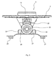
- the Fig. 5 shows a schematic front view of the burner base 6. The following is on the Fig. 2 to 5 simultaneously referred to.
- the burner lower part 6 is preferably arranged between the cover plate 4 and the hob trough 5.
- a burner upper part 6 of the gas burner 3 may protrude beyond the cover plate 4.
- the burner base 6 is preferably fixedly connected to the cover plate 4. In particular, the burner base 6 can be screwed to the cover plate 4.
- the burner base 6 has a support section or contact section 7, which is adapted to lie flat against the cover plate 4.
- a thermocouple receiving portion 8 for receiving a thermocouple of the gas burner 3 is integrated.
- an ignition element receiving section 9 for receiving an ignition element of the gas burner 3 is integrated in the contact section 7.
- the contact section 7 preferably has a plurality of support fingers 10 to 12, which extend radially outwards starting from an annular base section 13 of the burner lower part 6.
- the thermocouple receiving portion 8 and the Zündelementabilityabites 9 are integrated into a common support finger 10.
- the contact section 7 preferably has exactly three support fingers 10 to 12.
- the thermocouple receiving portion 8 is formed such that the thermocouple can be mounted in a plurality of different positions on the burner lower part 6. In particular, the thermocouple can be mounted in at least three different positions on the burner base 6. For this purpose, the thermocouple receiving portion 8 more provided in the common support finger 10 openings or recesses 14 to 16. The thermocouple is preferably in one of the recesses 14 to 16 pressed or clipped. Furthermore, the Zündelementabilityabêt 9 is formed such that the ignition element in several different positions on the burner lower part 6 is mountable. Preferably, the ignition element in at least three different positions on the burner lower part 6 can be mounted. For this purpose, the Zündelementabilityabêt 9 more provided in the common support finger 10 openings or recesses 17 to 19.
- the ignition element can be pressed or clipped into one of the recesses 17 to 19.
- a geometry of the thermocouple receiving portion 8 is different from a geometry of the igniter receiving portion 9, so that the thermocouple receiving portion 8 for receiving the thermocouple and the Zündelementmethodabites 9 is only suitable for receiving the ignition element.
- the recesses 14 to 16 or 17 to 19 have different diameters.
- the burner base 6 is preferably formed in one piece material.
- the burner base can be made of an aluminum or magnesium material.
- the burner lower part 6 is a metal die cast component.
- the contact section 7 has, as explained above, in addition to the common support finger 10 at least two further support fingers 11, 12.
- a nozzle receiving portion 20 for receiving a gas nozzle of the gas burner 3 extends from the common support finger 10 below the at least two other support fingers 11, 12.
- the nozzle receiving portion 20 is material integral with the common support finger 10 is formed.
- the nozzle receiving portion 20 extends so far below the at least two further support fingers 11, 12 that the nozzle receiving portion 20 projects beyond an opening 21 provided in the base portion 13.
- the nozzle receiving portion 20 is positioned so that a bore 22, in which the gas nozzle is receivable, is positioned centrally in the opening 21.
- fastening portions 23, 24 are provided for fixing the burner base 6 to the hob trough 5.
- a resiliently deformable fastening element 25 can be provided on the cooktop trough 5, which can be clipped onto the cooktop trough 5 without tools.
- the fastening element 25 may have at least one gripper arm 26, 27.
- the fastening element 25 has two gripping arms 26, 27.
- the gripping arms 26, 27 are resiliently deformable.
- the fastening element 25 further gripping arms 28, 29 have, which are adapted to engage around the mounting portions 23, 24 of the burner lower part 6 in a form-fitting manner.
- thermocouple and the ignition element Characterized in that on the burner lower part 6, the receiving portions 8, 9 are provided for the thermocouple and the ignition element, a particularly simple and quick installation of the thermocouple and the ignition element is possible. On additional fasteners can be omitted. By dispensing with additional fasteners increased tolerance requirements can be met. With the aid of the recesses 14 to 16 or 17 to 19, the thermocouple and the ignition element can be mounted in three different positions. As a result, the burner lower part 6 can be used for different sizes of gas burners 3.
Landscapes
- Engineering & Computer Science (AREA)
- Chemical & Material Sciences (AREA)
- Combustion & Propulsion (AREA)
- Mechanical Engineering (AREA)
- General Engineering & Computer Science (AREA)
- Gas Burners (AREA)
- Baking, Grill, Roasting (AREA)
Abstract
Description
- Die vorliegende Erfindung betrifft ein Brennerunterteil für einen Gasbrenner, einen Gasbrenner und eine Gaskochstelle.
- Zum Befestigen eines Thermoelements oder eines Zündelements eines Gasbrenners an einem Brennerunterteil desselben können das Thermoelement bzw. das Zündelement mit Hilfe von Zusatzelementen an dem Brennerunterteil festgeklemmt werden.
- Vor diesem Hintergrund besteht eine Aufgabe der vorliegenden Erfindung darin, ein verbessertes Brennerunterteil zur Verfügung zu stellen.
- Demgemäß wird ein Brennerunterteil für einen Gasbrenner mit einem Anlageabschnitt, der dazu eingerichtet ist, an einer Deckplatte einer Gaskochstelle flächig anzuliegen, einem in den Anlageabschnitt integrierten Thermoelementaufnahmeabschnitt zum Aufnehmen eines Thermoelements des Gasbrenners und einem in den Anlageabschnitt integrierten Zündelementaufnahmeabschnitt zum Aufnehmen eines Zündelements des Gasbrenners vorgeschlagen.
- Durch das Integrieren des Thermoelementaufnahmeabschnitts und des Zündelementaufnahmeabschnitts in den Anlageabschnitt kann eine Doppelfunktion verwirklicht werden. Zum einen kann auf dem Anlageabschnitt die Deckplatte aufliegen, zum anderen kann der Anlageabschnitt auch das Thermoelement und das Zündelement halten. Weiterhin kann dadurch, dass der Anlageabschnitt den Thermoelementaufnahmeabschnitt und den Zündelementaufnahmeabschnitt aufweist, auf Zusatzelemente zum Befestigen des Thermoelements oder des Zündelements verzichtet werden. Die Toleranzanforderungen sind im Vergleich zu einem System aus mehreren Bauteilen geringer. Der Anlageabschnitt kann auch als Auflageabschnitt bezeichnet werden.
- Gemäß einer Ausführungsform ist das Brennerunterteil materialeinstückig.
- Vorzugsweise ist das Brennerunterteil aus einem Aluminiummaterial oder einem Magnesiummaterial gefertigt. Vorzugsweise ist das Brennerunterteil ein Metalldruckgussbauteil. Gemäß einer weiteren Ausführungsform unterscheidet sich eine Geometrie des Thermoelementaufnahmeabschnitts von einer Geometrie des Zündelementaufnahmeabschnitts, so dass der Thermoelementaufnahmeabschnitt nur zur Aufnahme des Thermoelements und der Zündelementaufnahmeabschnitt nur zur Aufnahme des Zündelements geeignet ist.
- Vorzugsweise weisen der Thermoelementaufnahmeabschnitt und der Zündelementaufnahmeabschnitt mehrere Durchbrüche oder Bohrungen auf, deren Geometrien sich so unterscheiden, dass in den Thermoelementaufnahmeabschnitt nur das Thermoelement einführbar und in dem Zündelementaufnahmeabschnitt nur das Zündelement einführbar ist.
- Gemäß einer weiteren Ausführungsform ist der Thermoelementaufnahmeabschnitt derart ausgebildet, dass das Thermoelement in mehreren unterschiedlichen Positionen an dem Brennerunterteil montierbar ist.
- Vorzugsweise ist das Thermoelement in drei unterschiedlichen Positionen an dem Brennerunterteil montierbar. Hierdurch ist nur eine Variante des Brennerunterteils für verschiedene Größen von Gasbrennern erforderlich.
- Gemäß einer weiteren Ausführungsform ist der Zündelementaufnahmeabschnitt derart ausgebildet, dass das Zündelement in mehreren unterschiedlichen Positionen an dem Brennerunterteil montierbar ist.
- Vorzugsweise ist das Zündelement in drei unterschiedlichen Positionen an dem Brennerunterteil montierbar.
- Gemäß einer Ausführungsform weist der Anlageabschnitt mehrere Auflagefinger auf, die sich ausgehend von einem Basisabschnitt des Brennerunterteils radial nach außen erstrecken.
- Der Basisabschnitt ist vorzugsweise ringförmig und weist eine mittige Ausnehmung oder einen mittigen Durchbruch auf. Vorzugsweise weist der Anlageabschnitt genau drei Auflagefinger auf.
- Gemäß einer weiteren Ausführungsform sind der Thermoelementaufnahmeabschnitt und der Zündelementaufnahmeabschnitt in einen gemeinsamen Auflagefinger integriert.
- Hierdurch ist eine benachbarte Montage des Thermoelements und des Zündelements möglich.
- Gemäß einer weiteren Ausführungsform weist der Anlageabschnitt außer dem gemeinsamen Auflagefinger zumindest zwei weitere Auflagefinger auf.
- Die zwei weiteren Auflagefinger können schmäler als der gemeinsame Auflagefinger ausgebildet sein.
- Gemäß einer weiteren Ausführungsform erstreckt sich ein Düsenaufnahmeabschnitt zum Aufnehmen einer Gasdüse des Gasbrenners ausgehend von dem gemeinsamen Auflagefinger unterhalb die zumindest zwei weiteren Auflagefinger.
- Vorzugsweise ist der Düsenaufnahmeabschnitt materialeinstückig mit dem gemeinsamen Auflagefinger ausgebildet. Insbesondere ist die Gasdüse in den Düsenaufnahmeabschnitt einschraubbar.
- Gemäß einer Ausführungsform erstreckt sich der Düsenaufnahmeabschnitt so weit unterhalb die zumindest zwei weiteren Auflagefinger, dass der Düsenaufnahmeabschnitt über einen in einem Basisabschnitt des Brennerunterteils vorgesehenen Durchbruch hinausragt.
- Vorzugsweise ist die Gasdüse derart angeordnet, dass sie mittig in dem Durchbruch positioniert ist.
- Gemäß einer weiteren Ausführungsform ist das Brennerunterteil ein Metalldruckgussbauteil.
- Hierdurch kann das Brennerunterteil kostengünstig in hohen Stückzahlen hergestellt werden. Vorzugsweise ist das Brennerunterteil aus einem Aluminium- oder Magnesiummaterial gefertigt.
- Gemäß einer weiteren Ausführungsform weist das Brennerunterteil Befestigungsabschnitte zum Befestigen des Brennerunterteils an einer Kochmuldenwanne der Gaskochstelle auf.
- Die Befestigungsabschnitte sind beispielsweise mit einem an der Kochmuldenwanne befestigten Verbindungselement verbindbar. Insbesondere weist das Verbindungselement Greifarme auf, die über die Befestigungsabschnitte greifen können.
- Weiterhin wird ein Gasbrenner mit einem derartigen Brennerunterteil vorgeschlagen.
- Weiterhin wird eine Gaskochstelle mit einer Deckplatte, einem Brennerunterteil und/oder einem derartigen Gasbrenner vorgeschlagen.
- Die Gaskochstelle kann Teil eines Haushaltsgeräts sein.
- Gemäß einer Ausführungsform ist die Deckplatte eine Glaskeramik-, Glas- oder Keramikplatte.
- Weitere mögliche Implementierungen des Brennerunterteils, des Gasbrenners und/oder der Gaskochstelle umfassen auch nicht explizit genannte Kombinationen von zuvor oder im Folgenden bezüglich der Ausführungsbeispiele beschriebenen Merkmale oder Ausführungsformen. Dabei wird der Fachmann auch Einzelaspekte als Verbesserungen oder Ergänzungen zu der jeweiligen Grundform des Brennerunterteils, des Gasbrenners und/oder der Gaskochstelle hinzufügen.
- Weitere vorteilhafte Ausgestaltungen und Aspekte des Brennerunterteils, des Gasbrenners und/oder der Gaskochstelle sind Gegenstand der Unteransprüche sowie der im Folgenden beschriebenen Ausführungsbeispiele des Brennerunterteils, des Gasbrenners und/oder der Gaskochstelle. Im Weiteren werden das Brennerunterteil, der Gasbrenner und/oder die Gaskochstelle anhand von bevorzugten Ausführungsformen unter Bezugnahme auf die beigelegten Figuren näher erläutert.
- Fig. 1
- zeigt eine schematische Seitenansicht einer Ausführungsform eines Herds;
- Fig. 2
- zeigt eine schematische perspektivische Ansicht eines Brennerunterteils eines Gasbrenners des Herds gemäß der
Fig. 1 ; - Fig. 3
- zeigt eine schematische Aufsicht des Brennerunterteils gemäß der
Fig. 2 ; - Fig. 4
- zeigt eine weitere schematische perspektivische Ansicht des Brennerunterteils gemäß der
Fig. 2 ; und - Fig. 5
- zeigt eine schematische Vorderansicht des Brennerunterteils gemäß der
Fig. 2 . - In den Figuren sind gleiche oder funktionsgleiche Elemente mit denselben Bezugszeichen versehen worden, sofern nichts anderes angegeben ist.
- Die
Fig. 1 zeigt einen Herd 1 mit einer Gaskochstelle 2. Der Herd 1 ist insbesondere ein Gasherd. Die Gaskochstelle 2 umfasst zumindest einen Gasbrenner 3, eine Deckplatte 4 und eine unterhalb der Deckplatte 4 angeordnete Kochmuldenwanne 5. Die Deckplatte 4 kann eine Glaskeramik-, Glas- oder Keramikplatte sein. - Die
Fig. 2 zeigt in einer schematischen perspektivischen Ansicht ein Brennerunterteil 6 für den Gasbrenner 3. DieFig. 3 zeigt eine schematische Aufsicht des Brennerunterteils 6. DieFig. 4 zeigt eine weitere schematische Ansicht des Brennerunterteils 6. DieFig. 5 zeigt eine schematische Vorderansicht des Brennerunterteils 6. Im Folgenden wird auf dieFig. 2 bis 5 gleichzeitig Bezug genommen. - Das Brennerunterteil 6 ist vorzugsweise zwischen der Deckplatte 4 und der Kochmuldenwanne 5 angeordnet. Ein Brenneroberteil 6 des Gasbrenners 3 kann über die Deckplatte 4 hinausragen. Das Brennerunterteil 6 ist vorzugsweise mit der Deckplatte 4 fest verbunden. Insbesondere kann das Brennerunterteil 6 mit der Deckplatte 4 verschraubt sein.
- Das Brennerunterteil 6 weist einen Auflageabschnitt oder Anlageabschnitt 7 auf, der dazu eingerichtet ist, an der Deckplatte 4 flächig anzuliegen. In den Anlageabschnitt 7 ist ein Thermoelementaufnahmeabschnitt 8 zum Aufnehmen eines Thermoelements des Gasbrenners 3 integriert. Weiterhin ist in dem Anlageabschnitt 7 ein Zündelementaufnahmeabschnitt 9 zum Aufnehmen eines Zündelements des Gasbrenners 3 integriert.
- Der Anlageabschnitt 7 weist vorzugsweise mehrere Auflagefinger 10 bis 12 auf, die sich ausgehend von einem ringförmigen Basisabschnitt 13 des Brennerunterteils 6 radial nach außen erstrecken. Der Thermoelementaufnahmeabschnitt 8 und der Zündelementaufnahmeabschnitt 9 sind dabei in einen gemeinsamen Auflagefinger 10 integriert. Vorzugsweise weist der Anlageabschnitt 7 genau drei Auflagefinger 10 bis 12 auf.
- Der Thermoelementaufnahmeabschnitt 8 ist derart ausgebildet, dass das Thermoelement in mehreren unterschiedlichen Positionen an dem Brennerunterteil 6 montierbar ist. Insbesondere ist das Thermoelement in zumindest drei unterschiedlichen Positionen an dem Brennerunterteil 6 montierbar. Hierzu weist der Thermoelementaufnahmeabschnitt 8 mehrere in dem gemeinsamen Auflagefinger 10 vorgesehene Durchbrüche oder Ausnehmungen 14 bis 16 auf. Das Thermoelement ist vorzugsweise in eine der Ausnehmungen 14 bis 16 eindrückbar oder einclipsbar. Weiterhin ist auch der Zündelementaufnahmeabschnitt 9 derart ausgebildet, dass das Zündelement in mehreren unterschiedlichen Positionen an dem Brennerunterteil 6 montierbar ist. Vorzugsweise ist das Zündelement in zumindest drei unterschiedlichen Positionen an dem Brennerunterteil 6 montierbar. Hierzu weist der Zündelementaufnahmeabschnitt 9 mehrere in dem gemeinsamen Auflagefinger 10 vorgesehene Durchbrüche oder Ausnehmungen 17 bis 19 auf. Das Zündelement ist in eine der Ausnehmungen 17 bis 19 eindrückbar oder einclipsbar. Vorzugsweise unterscheidet sich eine Geometrie des Thermoelementaufnahmeabschnitts 8 von einer Geometrie des Zündelementaufnahmeabschnitts 9, so dass der Thermoelementaufnahmeabschnitt 8 nur zur Aufnahme des Thermoelements und der Zündelementaufnahmeabschnitt 9 nur zur Aufnahme des Zündelements geeignet ist. Hierzu können die Ausnehmungen 14 bis 16 bzw. 17 bis 19 unterschiedliche Durchmesser aufweisen.
- Das Brennerunterteil 6 ist vorzugsweise materialeinstückig ausgebildet. Insbesondere kann das Brennerunterteil aus einem Aluminium- oder Magnesiumwerkstoff hergestellt sein. Vorzugsweise ist das Brennerunterteil 6 ein Metalldruckgussbauteil.
- Der Anlageabschnitt 7 weist, wie zuvor erläutert, außer dem gemeinsamen Auflagefinger 10 zumindest zwei weitere Auflagefinger 11, 12 auf. Ein Düsenaufnahmeabschnitt 20 zum Aufnehmen einer Gasdüse des Gasbrenners 3 erstreckt sich ausgehend von dem gemeinsamen Auflagefinger 10 unterhalb die zumindest zwei weiteren Auflagefinger 11, 12. Insbesondere ist der Düsenaufnahmeabschnitt 20 materialeinstückig mit dem gemeinsamen Auflagefinger 10 ausgebildet. Weiterhin erstreckt sich der Düsenaufnahmeabschnitt 20 so weit unterhalb die zumindest zwei weiteren Auflagefinger 11, 12, dass der Düsenaufnahmeabschnitt 20 über einen in dem Basisabschnitt 13 vorgesehenen Durchbruch 21 herausragt. Insbesondere ist der Düsenaufnahmeabschnitt 20 so positioniert, dass eine Bohrung 22, in der die Gasdüse aufnehmbar ist, mittig in dem Durchbruch 21 positioniert ist.
- An dem Brennerunterteil 6 und insbesondere an dem Düsenaufnahmeabschnitt 20 sind Befestigungsabschnitte 23, 24 zum Befestigen des Brennerunterteils 6 an der Kochmuldenwanne 5 vorgesehen. Insbesondere kann an der Kochmuldenwanne 5 ein federelastisch verformbares Befestigungselement 25 vorgesehen sein, das werkzeuglos an die Kochmuldenwanne 5 anclipsbar sein kann. Hierzu kann das Befestigungselement 25 zumindest einen Greifarm 26, 27 aufweisen. Vorzugsweise weist das Befestigungselement 25 zwei Greifarme 26, 27 auf. Die Greifarme 26, 27 sind federelastisch verformbar. Weiterhin kann das Befestigungselement 25 weitere Greifarme 28, 29 aufweisen, die dazu eingerichtet sind, die Befestigungsabschnitte 23, 24 des Brennerunterteil 6 formschlüssig zu umgreifen.
- Dadurch, dass an dem Brennerunterteil 6 die Aufnahmeabschnitte 8, 9 für das Thermoelement und das Zündelement vorgesehen sind, ist eine besonders einfache und schnelle Montage des Thermoelements und des Zündelements möglich. Auf zusätzliche Befestigungselemente kann verzichtet werden. Durch den Verzicht auf zusätzliche Befestigungselemente können erhöhte Toleranzanforderungen erfüllt werden. Mit Hilfe der Ausnehmungen 14 bis 16 bzw. 17 bis 19 sind das Thermoelement und das Zündelement jeweils in drei unterschiedlichen Positionen montierbar. Hierdurch kann das Brennerunterteil 6 für verschiedene Größen von Gasbrennern 3 eingesetzt werden.
-
- 1
- Herd
- 2
- Gaskochstelle
- 3
- Gasbrenner
- 4
- Deckplatte
- 5
- Kochmuldenwanne
- 6
- Brennerunterteil
- 7
- Anlageabschnitt
- 8
- Thermoelementaufnahmeabschnitt
- 9
- Zündelementaufnahmeabschnitt
- 10
- Auflagefinger
- 11
- Auflagefinger
- 12
- Auflagefinger
- 13
- Basisabschnitt
- 14
- Ausnehmung
- 15
- Ausnehmung
- 16
- Ausnehmung
- 17
- Ausnehmung
- 18
- Ausnehmung
- 19
- Ausnehmung
- 20
- Düsenaufnahmeabschnitt
- 21
- Durchbruch
- 22
- Bohrung
- 23
- Befestigungsabschnitt
- 24
- Befestigungsabschnitt
- 25
- Befestigungselement
- 26
- Greifarm
- 27
- Greifarm
- 28
- Greifarm
- 29
- Greifarm
Claims (15)
- Brennerunterteil (6) für einen Gasbrenner (3), mit einem Anlageabschnitt (7), der dazu eingerichtet ist, an einer Deckplatte (4) einer Gaskochstelle (2) flächig anzuliegen, einem in den Anlageabschnitt (7) integrierten Thermoelementaufnahmeabschnitt (8) zum Aufnehmen eines Thermoelements des Gasbrenners (3) und einem in den Anlageabschnitt (7) integrierten Zündelementaufnahmeabschnitt (9) zum Aufnehmen eines Zündelements des Gasbrenners (3).
- Brennerunterteil nach Anspruch 1, dadurch gekennzeichnet, dass das Brennerunterteil (6) materialeinstückig ist.
- Brennerunterteil nach Anspruch 1 oder 2, dadurch gekennzeichnet, dass sich eine Geometrie des Thermoelementaufnahmeabschnitts (8) von einer Geometrie des Zündelementaufnahmeabschnitts (9) unterscheidet, so dass der Thermoelementaufnahmeabschnitt (8) nur zur Aufnahme des Thermoelements und der Zündelementaufnahmeabschnitt (9) nur zur Aufnahme des Zündelements geeignet ist.
- Brennerunterteil nach einem der Ansprüche 1 - 3, dadurch gekennzeichnet, dass der Thermoelementaufnahmeabschnitt (8) derart ausgebildet ist, dass das Thermoelement in mehreren unterschiedlichen Positionen an dem Brennerunterteil (6) montierbar ist.
- Brennerunterteil nach einem der Ansprüche 1 - 4, dadurch gekennzeichnet, dass der Zündelementaufnahmeabschnitt (9) derart ausgebildet ist, dass das Zündelement in mehreren unterschiedlichen Positionen an dem Brennerunterteil (6) montierbar ist.
- Brennerunterteil nach einem der Ansprüche 1 - 5, dadurch gekennzeichnet, dass der Anlageabschnitt (7) mehrere Auflagefinger (10 - 12) aufweist, die sich ausgehend von einem Basisabschnitt (13) des Brennerunterteils (6) radial nach außen erstrecken.
- Brennerunterteil nach Anspruch 6, dadurch gekennzeichnet, dass der Thermoelementaufnahmeabschnitt (8) und der Zündelementaufnahmeabschnitt (9) in einen gemeinsamen Auflagefinger (10) integriert sind.
- Brennerunterteil nach Anspruch 7, dadurch gekennzeichnet, dass der Anlageabschnitt (7) außer dem gemeinsamen Auflagefinger (10) zumindest zwei weitere Auflagefinger (11, 12) aufweist.
- Brennerunterteil nach Anspruch 8, dadurch gekennzeichnet, dass sich ein Düsenaufnahmeabschnitt (20) zum Aufnehmen einer Gasdüse des Gasbrenners (3) ausgehend von dem gemeinsamen Auflagefinger (10) unterhalb die zumindest zwei weiteren Auflagefinger (11, 12) erstreckt.
- Brennerunterteil nach Anspruch 9, dadurch gekennzeichnet, dass sich der Düsenaufnahmeabschnitt (20) so weit unterhalb die zumindest zwei weiteren Auflagefinger (11, 12) erstreckt, dass der Düsenaufnahmeabschnitt (20) über einen in einem Basisabschnitt (13) des Brennerunterteils (6) vorgesehenen Durchbruch (21) hinausragt.
- Brennerunterteil nach einem der Ansprüche 1 - 10, dadurch gekennzeichnet, dass das Brennerunterteil (6) ein Metalldruckgussbauteil ist.
- Brennerunterteil nach einem der Ansprüche 1 - 11, gekennzeichnet durch Befestigungsabschnitte (23, 24) zum Befestigen des Brennerunterteils (6) an einer Kochmuldenwanne (5) der Gaskochstelle (2).
- Gasbrenner (3) mit einem Brennerunterteil (6) nach einem der Ansprüche 1 - 12.
- Gaskochstelle (2) mit einer Deckplatte (4), einem Brennerunterteil (6) nach einem der Ansprüche 1 - 12 und/oder einem Gasbrenner (3) nach Anspruch 13.
- Gaskochstelle nach Anspruch 14, dadurch gekennzeichnet, dass die Deckplatte (4) eine Glaskeramik-, Glas- oder Keramikplatte ist.
Applications Claiming Priority (1)
| Application Number | Priority Date | Filing Date | Title |
|---|---|---|---|
| ES201431628A ES2569279B1 (es) | 2014-11-06 | 2014-11-06 | Parte inferior de quemador para un quemador de gas, quemador de gas, y punto de cocción a gas |
Publications (2)
| Publication Number | Publication Date |
|---|---|
| EP3018409A1 true EP3018409A1 (de) | 2016-05-11 |
| EP3018409B1 EP3018409B1 (de) | 2018-08-01 |
Family
ID=54396745
Family Applications (1)
| Application Number | Title | Priority Date | Filing Date |
|---|---|---|---|
| EP15192149.1A Active EP3018409B1 (de) | 2014-11-06 | 2015-10-29 | Gaskochstelle mit brennerunterteil für einen gasbrenner |
Country Status (2)
| Country | Link |
|---|---|
| EP (1) | EP3018409B1 (de) |
| ES (2) | ES2569279B1 (de) |
Cited By (1)
| Publication number | Priority date | Publication date | Assignee | Title |
|---|---|---|---|---|
| CN114593423A (zh) * | 2022-03-01 | 2022-06-07 | 芜湖美的智能厨电制造有限公司 | 一种燃烧装置及燃气灶 |
Citations (3)
| Publication number | Priority date | Publication date | Assignee | Title |
|---|---|---|---|---|
| EP0019231A1 (de) * | 1979-05-16 | 1980-11-26 | COMPAGNIE EUROPEENNE POUR L'EQUIPEMENT MENAGER "CEPEM" Société anonyme dite: | Gasbrenner |
| WO2006077058A1 (en) * | 2005-01-20 | 2006-07-27 | Defendi Italy S.R.L. | Gas burner, in particular for domestic cooking appliances |
| US20110129783A1 (en) * | 2009-12-01 | 2011-06-02 | Uwe Harneit | Burner with flame ring stabilization chamber |
Family Cites Families (4)
| Publication number | Priority date | Publication date | Assignee | Title |
|---|---|---|---|---|
| US5125390A (en) * | 1991-10-31 | 1992-06-30 | Robertshaw Controls Company | Cooking apparatus, burner construction therefor and methods of making the same |
| ITAN20020026A1 (it) * | 2002-06-11 | 2003-12-11 | Somi Press Soc Metalli Iniettati Spa | Corona per bruciatori a gas per fornelli da cucina |
| ITUD20020141A1 (it) * | 2002-06-25 | 2003-12-29 | Commital Sami Spa | Bruciatore a gas |
| EP2439454A1 (de) * | 2010-10-11 | 2012-04-11 | BSH Bosch und Siemens Hausgeräte GmbH | Gasbrenner für ein Gargerät |
-
2014
- 2014-11-06 ES ES201431628A patent/ES2569279B1/es not_active Revoked
-
2015
- 2015-10-29 ES ES15192149.1T patent/ES2683204T3/es active Active
- 2015-10-29 EP EP15192149.1A patent/EP3018409B1/de active Active
Patent Citations (3)
| Publication number | Priority date | Publication date | Assignee | Title |
|---|---|---|---|---|
| EP0019231A1 (de) * | 1979-05-16 | 1980-11-26 | COMPAGNIE EUROPEENNE POUR L'EQUIPEMENT MENAGER "CEPEM" Société anonyme dite: | Gasbrenner |
| WO2006077058A1 (en) * | 2005-01-20 | 2006-07-27 | Defendi Italy S.R.L. | Gas burner, in particular for domestic cooking appliances |
| US20110129783A1 (en) * | 2009-12-01 | 2011-06-02 | Uwe Harneit | Burner with flame ring stabilization chamber |
Cited By (1)
| Publication number | Priority date | Publication date | Assignee | Title |
|---|---|---|---|---|
| CN114593423A (zh) * | 2022-03-01 | 2022-06-07 | 芜湖美的智能厨电制造有限公司 | 一种燃烧装置及燃气灶 |
Also Published As
| Publication number | Publication date |
|---|---|
| ES2569279B1 (es) | 2017-02-15 |
| EP3018409B1 (de) | 2018-08-01 |
| ES2569279A1 (es) | 2016-05-09 |
| ES2683204T3 (es) | 2018-09-25 |
Similar Documents
| Publication | Publication Date | Title |
|---|---|---|
| WO2016157006A1 (de) | Gasbrenner und gaskochfeld | |
| DE102007032757A1 (de) | Kochvorrichtung | |
| EP3018409B1 (de) | Gaskochstelle mit brennerunterteil für einen gasbrenner | |
| WO2013175350A2 (de) | Gasbeheiztes gargerät | |
| EP3012536B1 (de) | Gaskochmulde | |
| EP3682165B1 (de) | Gasbrenner, gasbrenneranordnung und haushaltsgargerät | |
| DE19819732C1 (de) | Anordnung zur Befestigung eines atmosphärischen Gasbrenners an der Brenneröffnung einer Kochfläche aus Glas oder Glaskeramik sowie Kochfeld mit einer solchen Anordnung | |
| DE10306813B4 (de) | Kochfeld | |
| EP2952817B1 (de) | Gasventil mit einer Hausgeräte-Bedienanordnung und Herd | |
| EP3084311B1 (de) | Kochstelle | |
| EP3184911B1 (de) | System mit einem kochfeld und mit einer höhenverstellungsvorrichtung | |
| DE102015220812A1 (de) | Schutzvorrichtung für beschichtete Kochfeldplatten | |
| WO2016157005A1 (de) | Bedienknauf für ein haushaltsgerät | |
| EP2857751A1 (de) | Befestigungseinrichtung zum verdrehsicheren Befestigen einer Leitung an einem Gehäuse eines Haushaltsgerätes, Befestigungsanordnung für ein Haushaltsgerät und Haushaltsgerät | |
| EP3161386B1 (de) | Gaskochstelle | |
| EP3032370B1 (de) | Hausgeräte-bedienanordnung, gasventil und herd | |
| EP3077731B1 (de) | Haushaltsgerät mit einem gasbrenner | |
| DE102016202768B4 (de) | Kochfeldvorrichtung | |
| EP3215793A1 (de) | Gaskochmulde | |
| EP1024328A2 (de) | Gasbrenner für flache Kochmulden | |
| EP2960581B1 (de) | Kochmulde | |
| EP3096085B1 (de) | Haushaltgeräte-Bedienanordnung, Gasventil und Gaskochstelle | |
| EP2860455A1 (de) | Positioniereinrichtung zum Positionieren eines Gasbrenners in oder an einer Kochmulde, Kochmulde und Gasherd | |
| EP3048373B1 (de) | Gaskochstelle mit befestigungseinrichtung | |
| DE4436560C1 (de) | Anordnung zur Halterung einer Einbaueinheit, wie eines Glaskeramik-Kochfeldes |
Legal Events
| Date | Code | Title | Description |
|---|---|---|---|
| PUAI | Public reference made under article 153(3) epc to a published international application that has entered the european phase |
Free format text: ORIGINAL CODE: 0009012 |
|
| AK | Designated contracting states |
Kind code of ref document: A1 Designated state(s): AL AT BE BG CH CY CZ DE DK EE ES FI FR GB GR HR HU IE IS IT LI LT LU LV MC MK MT NL NO PL PT RO RS SE SI SK SM TR |
|
| AX | Request for extension of the european patent |
Extension state: BA ME |
|
| RIN1 | Information on inventor provided before grant (corrected) |
Inventor name: PALACIOS VALDUEZA, LUIS ANTONIO Inventor name: OCHOA TORRES, JOSE SALVADOR Inventor name: GUTIERREZ HUMARA, MELCA Inventor name: HERRERA ESTRADA, PEDRO Inventor name: CORRAL RICALDE, JAVIER Inventor name: PLACER MARURI, EMILIO Inventor name: ACOSTA HERRERO, LUIS Inventor name: LOPEZ ORTIZ, ALBERTO |
|
| 17P | Request for examination filed |
Effective date: 20161111 |
|
| RBV | Designated contracting states (corrected) |
Designated state(s): AL AT BE BG CH CY CZ DE DK EE ES FI FR GB GR HR HU IE IS IT LI LT LU LV MC MK MT NL NO PL PT RO RS SE SI SK SM TR |
|
| 17Q | First examination report despatched |
Effective date: 20170412 |
|
| GRAP | Despatch of communication of intention to grant a patent |
Free format text: ORIGINAL CODE: EPIDOSNIGR1 |
|
| RIC1 | Information provided on ipc code assigned before grant |
Ipc: F23D 14/04 20060101AFI20180126BHEP |
|
| INTG | Intention to grant announced |
Effective date: 20180221 |
|
| GRAS | Grant fee paid |
Free format text: ORIGINAL CODE: EPIDOSNIGR3 |
|
| GRAA | (expected) grant |
Free format text: ORIGINAL CODE: 0009210 |
|
| AK | Designated contracting states |
Kind code of ref document: B1 Designated state(s): AL AT BE BG CH CY CZ DE DK EE ES FI FR GB GR HR HU IE IS IT LI LT LU LV MC MK MT NL NO PL PT RO RS SE SI SK SM TR |
|
| REG | Reference to a national code |
Ref country code: GB Ref legal event code: FG4D Free format text: NOT ENGLISH |
|
| REG | Reference to a national code |
Ref country code: CH Ref legal event code: EP Ref country code: AT Ref legal event code: REF Ref document number: 1024736 Country of ref document: AT Kind code of ref document: T Effective date: 20180815 |
|
| REG | Reference to a national code |
Ref country code: IE Ref legal event code: FG4D Free format text: LANGUAGE OF EP DOCUMENT: GERMAN |
|
| REG | Reference to a national code |
Ref country code: DE Ref legal event code: R096 Ref document number: 502015005286 Country of ref document: DE |
|
| REG | Reference to a national code |
Ref country code: ES Ref legal event code: FG2A Ref document number: 2683204 Country of ref document: ES Kind code of ref document: T3 Effective date: 20180925 |
|
| REG | Reference to a national code |
Ref country code: NL Ref legal event code: MP Effective date: 20180801 |
|
| REG | Reference to a national code |
Ref country code: LT Ref legal event code: MG4D |
|
| PG25 | Lapsed in a contracting state [announced via postgrant information from national office to epo] |
Ref country code: LT Free format text: LAPSE BECAUSE OF FAILURE TO SUBMIT A TRANSLATION OF THE DESCRIPTION OR TO PAY THE FEE WITHIN THE PRESCRIBED TIME-LIMIT Effective date: 20180801 Ref country code: RS Free format text: LAPSE BECAUSE OF FAILURE TO SUBMIT A TRANSLATION OF THE DESCRIPTION OR TO PAY THE FEE WITHIN THE PRESCRIBED TIME-LIMIT Effective date: 20180801 Ref country code: IS Free format text: LAPSE BECAUSE OF FAILURE TO SUBMIT A TRANSLATION OF THE DESCRIPTION OR TO PAY THE FEE WITHIN THE PRESCRIBED TIME-LIMIT Effective date: 20181201 Ref country code: PL Free format text: LAPSE BECAUSE OF FAILURE TO SUBMIT A TRANSLATION OF THE DESCRIPTION OR TO PAY THE FEE WITHIN THE PRESCRIBED TIME-LIMIT Effective date: 20180801 Ref country code: NO Free format text: LAPSE BECAUSE OF FAILURE TO SUBMIT A TRANSLATION OF THE DESCRIPTION OR TO PAY THE FEE WITHIN THE PRESCRIBED TIME-LIMIT Effective date: 20181101 Ref country code: GR Free format text: LAPSE BECAUSE OF FAILURE TO SUBMIT A TRANSLATION OF THE DESCRIPTION OR TO PAY THE FEE WITHIN THE PRESCRIBED TIME-LIMIT Effective date: 20181102 Ref country code: FI Free format text: LAPSE BECAUSE OF FAILURE TO SUBMIT A TRANSLATION OF THE DESCRIPTION OR TO PAY THE FEE WITHIN THE PRESCRIBED TIME-LIMIT Effective date: 20180801 Ref country code: SE Free format text: LAPSE BECAUSE OF FAILURE TO SUBMIT A TRANSLATION OF THE DESCRIPTION OR TO PAY THE FEE WITHIN THE PRESCRIBED TIME-LIMIT Effective date: 20180801 Ref country code: NL Free format text: LAPSE BECAUSE OF FAILURE TO SUBMIT A TRANSLATION OF THE DESCRIPTION OR TO PAY THE FEE WITHIN THE PRESCRIBED TIME-LIMIT Effective date: 20180801 Ref country code: BG Free format text: LAPSE BECAUSE OF FAILURE TO SUBMIT A TRANSLATION OF THE DESCRIPTION OR TO PAY THE FEE WITHIN THE PRESCRIBED TIME-LIMIT Effective date: 20181101 |
|
| PG25 | Lapsed in a contracting state [announced via postgrant information from national office to epo] |
Ref country code: HR Free format text: LAPSE BECAUSE OF FAILURE TO SUBMIT A TRANSLATION OF THE DESCRIPTION OR TO PAY THE FEE WITHIN THE PRESCRIBED TIME-LIMIT Effective date: 20180801 Ref country code: LV Free format text: LAPSE BECAUSE OF FAILURE TO SUBMIT A TRANSLATION OF THE DESCRIPTION OR TO PAY THE FEE WITHIN THE PRESCRIBED TIME-LIMIT Effective date: 20180801 Ref country code: AL Free format text: LAPSE BECAUSE OF FAILURE TO SUBMIT A TRANSLATION OF THE DESCRIPTION OR TO PAY THE FEE WITHIN THE PRESCRIBED TIME-LIMIT Effective date: 20180801 |
|
| PG25 | Lapsed in a contracting state [announced via postgrant information from national office to epo] |
Ref country code: CZ Free format text: LAPSE BECAUSE OF FAILURE TO SUBMIT A TRANSLATION OF THE DESCRIPTION OR TO PAY THE FEE WITHIN THE PRESCRIBED TIME-LIMIT Effective date: 20180801 Ref country code: RO Free format text: LAPSE BECAUSE OF FAILURE TO SUBMIT A TRANSLATION OF THE DESCRIPTION OR TO PAY THE FEE WITHIN THE PRESCRIBED TIME-LIMIT Effective date: 20180801 Ref country code: EE Free format text: LAPSE BECAUSE OF FAILURE TO SUBMIT A TRANSLATION OF THE DESCRIPTION OR TO PAY THE FEE WITHIN THE PRESCRIBED TIME-LIMIT Effective date: 20180801 |
|
| REG | Reference to a national code |
Ref country code: DE Ref legal event code: R097 Ref document number: 502015005286 Country of ref document: DE |
|
| PG25 | Lapsed in a contracting state [announced via postgrant information from national office to epo] |
Ref country code: SK Free format text: LAPSE BECAUSE OF FAILURE TO SUBMIT A TRANSLATION OF THE DESCRIPTION OR TO PAY THE FEE WITHIN THE PRESCRIBED TIME-LIMIT Effective date: 20180801 Ref country code: DK Free format text: LAPSE BECAUSE OF FAILURE TO SUBMIT A TRANSLATION OF THE DESCRIPTION OR TO PAY THE FEE WITHIN THE PRESCRIBED TIME-LIMIT Effective date: 20180801 Ref country code: SM Free format text: LAPSE BECAUSE OF FAILURE TO SUBMIT A TRANSLATION OF THE DESCRIPTION OR TO PAY THE FEE WITHIN THE PRESCRIBED TIME-LIMIT Effective date: 20180801 |
|
| REG | Reference to a national code |
Ref country code: CH Ref legal event code: PL |
|
| PLBE | No opposition filed within time limit |
Free format text: ORIGINAL CODE: 0009261 |
|
| STAA | Information on the status of an ep patent application or granted ep patent |
Free format text: STATUS: NO OPPOSITION FILED WITHIN TIME LIMIT |
|
| REG | Reference to a national code |
Ref country code: BE Ref legal event code: MM Effective date: 20181031 |
|
| PG25 | Lapsed in a contracting state [announced via postgrant information from national office to epo] |
Ref country code: MC Free format text: LAPSE BECAUSE OF FAILURE TO SUBMIT A TRANSLATION OF THE DESCRIPTION OR TO PAY THE FEE WITHIN THE PRESCRIBED TIME-LIMIT Effective date: 20180801 Ref country code: LU Free format text: LAPSE BECAUSE OF NON-PAYMENT OF DUE FEES Effective date: 20181029 |
|
| 26N | No opposition filed |
Effective date: 20190503 |
|
| REG | Reference to a national code |
Ref country code: IE Ref legal event code: MM4A |
|
| PG25 | Lapsed in a contracting state [announced via postgrant information from national office to epo] |
Ref country code: LI Free format text: LAPSE BECAUSE OF NON-PAYMENT OF DUE FEES Effective date: 20181031 Ref country code: CH Free format text: LAPSE BECAUSE OF NON-PAYMENT OF DUE FEES Effective date: 20181031 Ref country code: SI Free format text: LAPSE BECAUSE OF FAILURE TO SUBMIT A TRANSLATION OF THE DESCRIPTION OR TO PAY THE FEE WITHIN THE PRESCRIBED TIME-LIMIT Effective date: 20180801 Ref country code: FR Free format text: LAPSE BECAUSE OF NON-PAYMENT OF DUE FEES Effective date: 20181031 Ref country code: BE Free format text: LAPSE BECAUSE OF NON-PAYMENT OF DUE FEES Effective date: 20181031 |
|
| PG25 | Lapsed in a contracting state [announced via postgrant information from national office to epo] |
Ref country code: IE Free format text: LAPSE BECAUSE OF NON-PAYMENT OF DUE FEES Effective date: 20181029 |
|
| PG25 | Lapsed in a contracting state [announced via postgrant information from national office to epo] |
Ref country code: MT Free format text: LAPSE BECAUSE OF FAILURE TO SUBMIT A TRANSLATION OF THE DESCRIPTION OR TO PAY THE FEE WITHIN THE PRESCRIBED TIME-LIMIT Effective date: 20180801 |
|
| PG25 | Lapsed in a contracting state [announced via postgrant information from national office to epo] |
Ref country code: PT Free format text: LAPSE BECAUSE OF FAILURE TO SUBMIT A TRANSLATION OF THE DESCRIPTION OR TO PAY THE FEE WITHIN THE PRESCRIBED TIME-LIMIT Effective date: 20180801 |
|
| PG25 | Lapsed in a contracting state [announced via postgrant information from national office to epo] |
Ref country code: MK Free format text: LAPSE BECAUSE OF NON-PAYMENT OF DUE FEES Effective date: 20180801 Ref country code: HU Free format text: LAPSE BECAUSE OF FAILURE TO SUBMIT A TRANSLATION OF THE DESCRIPTION OR TO PAY THE FEE WITHIN THE PRESCRIBED TIME-LIMIT; INVALID AB INITIO Effective date: 20151029 Ref country code: CY Free format text: LAPSE BECAUSE OF FAILURE TO SUBMIT A TRANSLATION OF THE DESCRIPTION OR TO PAY THE FEE WITHIN THE PRESCRIBED TIME-LIMIT Effective date: 20180801 |
|
| GBPC | Gb: european patent ceased through non-payment of renewal fee |
Effective date: 20191029 |
|
| PG25 | Lapsed in a contracting state [announced via postgrant information from national office to epo] |
Ref country code: GB Free format text: LAPSE BECAUSE OF NON-PAYMENT OF DUE FEES Effective date: 20191029 |
|
| REG | Reference to a national code |
Ref country code: AT Ref legal event code: MM01 Ref document number: 1024736 Country of ref document: AT Kind code of ref document: T Effective date: 20201029 |
|
| PG25 | Lapsed in a contracting state [announced via postgrant information from national office to epo] |
Ref country code: AT Free format text: LAPSE BECAUSE OF NON-PAYMENT OF DUE FEES Effective date: 20201029 |
|
| PGFP | Annual fee paid to national office [announced via postgrant information from national office to epo] |
Ref country code: ES Payment date: 20221118 Year of fee payment: 8 Ref country code: DE Payment date: 20221031 Year of fee payment: 8 |
|
| REG | Reference to a national code |
Ref country code: DE Ref legal event code: R119 Ref document number: 502015005286 Country of ref document: DE |
|
| PG25 | Lapsed in a contracting state [announced via postgrant information from national office to epo] |
Ref country code: DE Free format text: LAPSE BECAUSE OF NON-PAYMENT OF DUE FEES Effective date: 20240501 |
|
| REG | Reference to a national code |
Ref country code: ES Ref legal event code: FD2A Effective date: 20241216 |
|
| PG25 | Lapsed in a contracting state [announced via postgrant information from national office to epo] |
Ref country code: ES Free format text: LAPSE BECAUSE OF NON-PAYMENT OF DUE FEES Effective date: 20231030 |
|
| PG25 | Lapsed in a contracting state [announced via postgrant information from national office to epo] |
Ref country code: ES Free format text: LAPSE BECAUSE OF NON-PAYMENT OF DUE FEES Effective date: 20231030 |
|
| PGFP | Annual fee paid to national office [announced via postgrant information from national office to epo] |
Ref country code: IT Payment date: 20251031 Year of fee payment: 11 |
|
| PGFP | Annual fee paid to national office [announced via postgrant information from national office to epo] |
Ref country code: TR Payment date: 20251024 Year of fee payment: 11 |