EP3018780B1 - Elektrisches anschlusskabel für leuchtenmodul - Google Patents
Elektrisches anschlusskabel für leuchtenmodul Download PDFInfo
- Publication number
- EP3018780B1 EP3018780B1 EP15193430.4A EP15193430A EP3018780B1 EP 3018780 B1 EP3018780 B1 EP 3018780B1 EP 15193430 A EP15193430 A EP 15193430A EP 3018780 B1 EP3018780 B1 EP 3018780B1
- Authority
- EP
- European Patent Office
- Prior art keywords
- electrical
- plug
- electrical connection
- light module
- connection cable
- Prior art date
- Legal status (The legal status is an assumption and is not a legal conclusion. Google has not performed a legal analysis and makes no representation as to the accuracy of the status listed.)
- Active
Links
Images


Classifications
-
- H—ELECTRICITY
- H02—GENERATION; CONVERSION OR DISTRIBUTION OF ELECTRIC POWER
- H02G—INSTALLATION OF ELECTRIC CABLES OR LINES, OR OF COMBINED OPTICAL AND ELECTRIC CABLES OR LINES
- H02G15/00—Cable fittings
- H02G15/013—Sealing means for cable inlets
-
- F—MECHANICAL ENGINEERING; LIGHTING; HEATING; WEAPONS; BLASTING
- F21—LIGHTING
- F21V—FUNCTIONAL FEATURES OR DETAILS OF LIGHTING DEVICES OR SYSTEMS THEREOF; STRUCTURAL COMBINATIONS OF LIGHTING DEVICES WITH OTHER ARTICLES, NOT OTHERWISE PROVIDED FOR
- F21V5/00—Refractors for light sources
- F21V5/007—Array of lenses or refractors for a cluster of light sources, e.g. for arrangement of multiple light sources in one plane
-
- F—MECHANICAL ENGINEERING; LIGHTING; HEATING; WEAPONS; BLASTING
- F21—LIGHTING
- F21V—FUNCTIONAL FEATURES OR DETAILS OF LIGHTING DEVICES OR SYSTEMS THEREOF; STRUCTURAL COMBINATIONS OF LIGHTING DEVICES WITH OTHER ARTICLES, NOT OTHERWISE PROVIDED FOR
- F21V23/00—Arrangement of electric circuit elements in or on lighting devices
- F21V23/06—Arrangement of electric circuit elements in or on lighting devices the elements being coupling devices, e.g. connectors
-
- F—MECHANICAL ENGINEERING; LIGHTING; HEATING; WEAPONS; BLASTING
- F21—LIGHTING
- F21Y—INDEXING SCHEME ASSOCIATED WITH SUBCLASSES F21K, F21L, F21S and F21V, RELATING TO THE FORM OR THE KIND OF THE LIGHT SOURCES OR OF THE COLOUR OF THE LIGHT EMITTED
- F21Y2105/00—Planar light sources
- F21Y2105/10—Planar light sources comprising a two-dimensional [2D] array of point-like light-generating elements
-
- F—MECHANICAL ENGINEERING; LIGHTING; HEATING; WEAPONS; BLASTING
- F21—LIGHTING
- F21Y—INDEXING SCHEME ASSOCIATED WITH SUBCLASSES F21K, F21L, F21S and F21V, RELATING TO THE FORM OR THE KIND OF THE LIGHT SOURCES OR OF THE COLOUR OF THE LIGHT EMITTED
- F21Y2115/00—Light-generating elements of semiconductor light sources
- F21Y2115/10—Light-emitting diodes [LED]
Definitions
- the present invention relates to an electrical connection cable for a light module, in particular for energy supply or for connecting control lines for the light module, and a corresponding light module with a connection cable.
- lighting devices which are connected to an electrical line in such a way that the passage of the cable into a lamp housing is completely sealed.
- An example of such a lighting device with an electrical line is in the DE 10 2011 075 032 A1 described.
- connection cable is firmly connected to the lamp module. It can therefore not be removed for maintenance work.
- a lighting device with a sealing element is provided.
- the cable bushing In order to seal a cable bushing in a luminaire housing, the cable bushing has a rubber seal that bears against a circumference of the cable itself.
- the assembly and disassembly of the connecting cable is relatively complex in this construction and can usually only be carried out by hand.
- DE 103 50 724 A1 discloses an electrical connection line with a plug in which a circuit board with plug contacts is cast.
- WO 2013/021017 A1 discloses an electrical device with a sealing element which is connected to a housing of an LED light module.
- the sealing element comprises a rubber-elastic body which is attached to a connecting line.
- the rubber-elastic body is inserted into a side wall of the lamp housing with a groove and fixed with a cover on the opposite side.
- GB 2 323 483 A discloses an electrical connection line according to the preamble of claim 1.
- the object of the present invention is to provide an electrical connection cable for a lamp module and a lamp module with a corresponding connection cable, which can be easily installed, is particularly suitable for automated assembly, and also seals the lamp module in the area of the cable duct.
- the electrical connection cable provides a special adapter plug at the end near the luminaire, which can be mounted directly on an opening in the luminaire housing of the luminaire module and also enables the luminaire module to be sealed in the area of the opening.
- the adapter connector is made up of a small circuit board and a connector housing, wherein the circuit board is connected to the connector housing by a potting material, which at the same time ensures that the circuit board is sealed with the connector housing.
- the unit comprising the circuit board and the plug housing is firmly connected to one, preferably at least two, wires of the electrical connection cable.
- the potting material is also intended to tightly pour the wires of the electrical connection cable into the adapter plug.
- the potting material can also provide strain relief for the electrical cable in this way.
- the potting material therefore has the task of mechanically holding the adapter plug together, mechanically holding the cable and sealing the adapter plug including the cable as a whole.
- the entire circuit board is not covered with potting material.
- the one or more second contact points are free of potting compound.
- the adapter plug is fastened in the opening of the lamp module. Subsequently, from the inside of the lamp module, electrical components, such as a circuit board, which carries lamps of the lamp module, can be connected to the second contact point with an electrical cable, of which two or more are preferably present.
- the plug housing has a flange which, when the connecting cable is mounted on the light module, bears on a circumference of the opening of the light module on an outside or inside of the light module.
- the flange can serve to seal the light module with the adapter plug in the area of the opening.
- the flange can lie against the wall section from the inside or outside in the region of the circumference of the opening in the lamp module, depending on whether the construction provides for the adapter plug to be fastened from the inside to the outside or from the outside to the inside in the opening of the lamp module. Both options are taken into account in the context of the invention. Installation from the outside in is preferred because the latching connections for holding the adapter plug are on the inside where they cannot be opened unintentionally.
- the adapter plug has a seal which seals the adapter plug to the inside or outside of the lamp module.
- the seal can be formed by an O-ring, which is preferably arranged in a groove of the adapter plug along the flange.
- the means for fastening the adapter plug in the opening are formed by latching means which can be latched in the area of the opening of the lamp module.
- latching means which can be latched in the area of the opening of the lamp module.
- the plug housing comprises an insertion slot into which the circuit board is inserted. Furthermore, the circuit board and the connector housing have latching means which hold the circuit board in the insertion slot before the circuit board is fastened and sealed to the connector housing by the potting material.
- This structure facilitates the assembly of the connector.
- the insertion slot ensures that the board is placed precisely opposite the connector housing.
- the locking means ensure that the adapter plug is held together temporarily before the potting material solidifies.
- a potting material is preferably used which retains a residual toughness after solidification.
- the at least second contact point is formed by a connection terminal, in particular a "BJB terminal".
- a light-side cable for connection to electrical components within the light module e.g. a circuit board with light sources can be easily held mechanically and electrically contacted.
- At least two such connection terminals are preferably provided for two second contact points.
- the at least one, preferably more than one, first contact point has a soldering point.
- the at least one electrical wire of the electrical connection cable is attached to the first contact point on the circuit board of the adapter plug by soldering. This connection can be made easily by machine and is preferred since it does not need to be opened again for the maintenance of the lamp module.
- the solder joint can, in particular, be completely cast in from the potting material.
- a plug is provided at the end of the electrical connection line which is distant from the lamp and is preferably attached to the at least one wire of the electrical line and electrically contacted by crimping.
- the open end of the electrical connection cable must first be passed through the plug housing of the adapter plug before the board of the adapter plug is fastened in the plug housing. In this step, it is advantageous that no connector is yet attached to the end of the electrical connection cable that is distant from the lamp. This is only attached in a subsequent step. Crimping is particularly suitable for this, although other types of connection, such as soldering, are also possible.
- the lamp module of the present invention comprises an electrical connection line as described above, and a module housing in which the opening is provided, in which the adapter plug is mounted, and a circuit board on which lamps are arranged, the circuit board with the lamps being electrically connected to the at least a second contact point of the adapter plug is connected.
- the luminaire module cannot be a complete luminaire, or only part of a luminaire with its own housing, whereby components of the luminaire, e.g. a ballast can be arranged externally.
- LEDs are preferred as illuminants.
- the electrical connection line of the described embodiments is particularly suitable for the voltages required to supply LEDs.
- the lamp module with the electrical connection cable mounted thereon i.e. with plugged-in adapter plug, moisture-proof or gas-tight.
- protection classes IP 65 or IP 66 can be implemented.
- FIG. 1 the structure of an electrical connection cable is shown, which for a lamp module, as in the Figure 5 is shown, is provided.
- the electrical connection cable has an end near the light (in Figure 1 to 3 left) and a distant end (in Figures 1 to 3 right).
- an adapter plug 2 which comprises a plug housing 4 and a circuit board 6 and an O-ring 8.
- individual wires 10 of an electrical line 1 are first soldered to first contact points 12 of the circuit board 6.
- the first electrical contact points 12 are connected via conductor tracks on the circuit board 6 to second electrical contact points 14 in the form of terminals, in which electrical lines can be clamped in the light module (see Figure 6 ).
- the electrical line 1 is passed through the connector housing 4 and the circuit board is inserted into an insertion slot of the connector housing 4.
- locking projections 16 are provided, which engage in side windows 17 in the insertion slot of the housing connector 4.
- the adapter plug 4 already holds together.
- a casting compound is applied in the area of the circuit board 6 and the plug housing 4, as by the hatched area 18 in Figure 4 shown.
- the potting compound 18 not only holds the board 6 to the connector housing 4, but also provides a seal so that no moisture and / or no gas can penetrate through the adapter connector 4 itself.
- the connector housing 4 also has a flange 20 which extends in a plane perpendicular to the longitudinal extent of the electrical line 1.
- the flange 20 is intended to lie together with the O-ring 8 on the circumference of an opening 22 in the lamp module.
- the adapter plug 2 is inserted into the opening 22 of the lamp module.
- the O-ring 8 is clamped between the flange and the outer wall of the lamp module, so that a seal is achieved.
- two pins 24 are provided, on which the adapter plug can be easily gripped by a robot in order to automatically insert it into the opening 22 of the lamp module.
- the adapter plug 2 has, in the area of the plug housing 4, locking projections 26 which engage behind the opening 22 on the inside of the lamp module. As a result, the adapter plug 2 is mechanically held in the opening 22.
- connection terminals of the second contact points 14 on the inside can be connected to the connection terminals of the second contact points 14 on the inside, as in FIG Figure 6 is shown. Since the connection terminals make electrical and mechanical contact with the wire at the same time, this connection can also be made automatically by a robot.
- a further plug 30 is provided in order to connect the light module to an electrical power supply.
- a connector 30 is preferably provided, in which electrical pins of the connector 30 are crimped directly onto the wires 10 of the electrical line 1 and a plastic housing is pushed over the electrical pins.
- a board 34 is provided in the interior of the lamp module, on which a large number of lamps in the form of LEDs are attached. Lens elements 31 are arranged above the LEDs in one plane and are attached to the circuit board 34.
- the light module is closed from the light exit side of the module by a transparent cover 38.
Landscapes
- Engineering & Computer Science (AREA)
- General Engineering & Computer Science (AREA)
- Arrangement Of Elements, Cooling, Sealing, Or The Like Of Lighting Devices (AREA)
Description
- Die vorliegende Erfindung betrifft ein elektrisches Anschlusskabel für ein Leuchtenmodul, insbesondere zur Energieversorgung oder zum Anschluss von Steuerleitungen für das Leuchtenmodul, sowie ein entsprechendes Leuchtenmodul mit Anschlusskabel.
- Aus dem Stand der Technik sind Leuchtvorrichtungen bekannt, welche mit einer elektrischen Leitung derart verbunden sind, dass die Durchführung des Kabels in ein Leuchtengehäuse vollständig abgedichtet ist. Ein Beispiel einer solchen Leuchtvorrichtung mit einer elektrischen Leitung ist in der
DE 10 2011 075 032 A1 beschrieben. - Dieser Stand der Technik hat jedoch den Nachteil, dass das Anschlusskabel fest mit dem Leuchtenmodul verbunden ist. Es lässt sich daher auch zu Wartungsarbeiten nicht abnehmen.
- Aus der
DE 10 2010 033 297 A1 ist eine Beleuchtungsvorrichtung mit einem Dichtelement vorgesehen. Um eine Kabeldurchführung in einem Leuchtengehäuse abzudichten, weist die Kabeldurchführung eine Gummidichtung auf, die an einem Umfang des Kabels selbst anliegt. Die Montage und Demontage des Anschlusskabels ist bei dieser Konstruktion jedoch verhältnismäßig aufwendig und kann in der Regel nur von Hand durchgeführt werden. -
DE 103 50 724 A1 offenbart eine elektrische Anschlussleitung mit einem Stecker, in welchem eine Platine mit Steckkontakten eingegossen ist. -
WO 2013/021017 A1 offenbart eine elektrische Vorrichtung mit einem Dichtungselement, welche an ein Gehäuse eines LED-Leuchtenmoduls angeschlossen ist. Das Dichtungselement umfasst einen gummielastischen Körper, welcher auf eine Anschlussleitung aufgesteckt ist. Der gummielastische Körper wird mit einer Nut in eine Seitenwand des Leuchtengehäuses eingesteckt und mit einem Deckel auf der gegenüberliegenden Seite fixiert. -
GB 2 323 483 A - Aufgabe der vorliegenden Erfindung ist es, ein elektrisches Anschlusskabel für ein Leuchtenmodul sowie ein Leuchtenmodul mit entsprechendem Anschlusskabel bereitzustellen, welches einfach montiert werden kann, insbesondere für eine automatisierte Montage geeignet ist, und außerdem das Leuchtenmodul im Bereich der Kabeldurchführung abdichtet.
- Gelöst wird die Aufgabe durch ein elektrisches Anschlusskabel gemäß Anspruch 1 sowie durch ein Leuchtenmodul mit elektrischem Anschlusskabel nach Anspruch 11.
- Das elektrische Anschlusskabel sieht am leuchtennahen Ende einen speziellen Adapterstecker vor, welcher direkt an einer Öffnung des Leuchtengehäuses des Leuchtenmoduls montiert werden kann und dabei auch eine Abdichtung des Leuchtenmoduls im Bereich der Öffnung ermöglicht. Der Adapterstecker ist aus einer kleinen Platine und einem Steckergehäuse aufgebaut, wobei die Platine mit dem Steckergehäuse durch ein Vergussmaterial verbunden werden, welches gleichzeitig dafür sorgt, dass die Platine mit dem Steckergehäuse abgedichtet wird. Die Einheit aus Platine und Steckergehäuse ist fest mit einer, vorzugsweise wenigstens zwei Adern des elektrischen Anschlusskabels verbunden. Das Vergussmaterial ist auch dafür vorgesehen, die Adern des elektrischen Anschlusskabels in dem Adapterstecker dicht einzugießen. Das Vergussmaterial kann auf diese Weise auch für eine Zugentlastung des elektrischen Kabels sorgen. Das Vergussmaterial hat also die Aufgabe, den Adapterstecker mechanisch zusammenzuhalten, das Kabel mechanisch zu halten und den Adapterstecker einschließlich des Kabels insgesamt abzudichten. Vorzugsweise ist nicht die gesamte Platine mit Vergussmaterial abgedeckt. Insbesondere sind die eine oder die mehreren zweiten Kontaktstellen frei von Vergussmasse.
- Der Adapterstecker wird in der Öffnung des Leuchtenmoduls befestigt. Anschließend können von der Innenseite des Leuchtenmoduls elektrische Komponenten, wie eine Platine, welche Leuchtmittel des Leuchtenmoduls trägt, mit einem elektrischen Kabel an der zweiten Kontaktstelle, wovon vorzugsweise zwei oder mehr vorhanden sind, angeschlossen werden.
- Gemäß einer bevorzugten Ausführungsform weist das Steckergehäuse einen Flansch auf, welcher im am Leuchtemodul montierten Zustand des Anschlusskabels an einem Umfang der Öffnung des Leuchtemoduls an einer Außen- oder Innenseite des Leuchtemoduls anliegt. Der Flansch kann dazu dienen, das Leuchtemodul mit dem Adapterstecker im Bereich der Öffnung abzudichten. Der Flansch kann von der Innen- oder Außenseite an dem Wandabschnitt im Bereich des Umfangs der Öffnung in dem Leuchtenmodul anliegen, abhängig davon, ob die Konstruktion vorsieht, den Adapterstecker von innen nach außen oder von außen nach innen in der Öffnung des Leuchtenmoduls zu befestigen. Beide Möglichkeiten sind im Rahmen der Erfindung berücksichtigt. Bevorzugt ist die Montage von außen nach innen, weil die Rastverbindungen zum Halten des Adaptersteckers dann auf der Innenseite liegen, wo sie nicht unbeabsichtigt geöffnet werden können.
- Gemäß einer bevorzugten Ausführungsform weist der Adapterstecker eine Dichtung auf, welche den Adapterstecker zu der Innen- oder Außenseite des Leuchtenmoduls abdichtet. Insbesondere in Verbindung mit der Ausführungsform, in welcher der Adapterstecker einen Flansch vorsieht, kann die Dichtung durch einen O-Ring gebildet werden, welcher vorzugsweise in einer Nut des Adaptersteckers entlang des Flansches angeordnet ist.
- Gemäß einer bevorzugten Ausführungsform sind die Mittel zur Befestigung des Adaptersteckers in der Öffnung durch Rastmittel gebildet, welche im Bereich der Öffnung des Leuchtenmoduls einrastbar sind. Diese Verbindungsart ist besonders einfach. Insbesondere bei einer vollautomatisierten Montage kann der Adapterstecker durch die Rastmittel leicht in der Öffnung des Leuchtenmoduls befestigt werden.
- Erfindungsgemäß umfasst das Steckergehäuse einen Einschubschlitz, in welchem die Platine eingeschoben ist. Ferner weist die Platine und das Steckergehäuse Rastmittel auf, welche die Platine in dem Einschubschlitz halten, bevor die Platine an dem Steckergehäuse durch das Vergussmaterial befestigt und abgedichtet wird. Dieser Aufbau erleichtert die Montage des Anschlusssteckers. Der Einschubschlitz sorgt dafür, dass die Platine präzise gegenüber dem Steckergehäuse platziert wird. Die Rastmittel sorgen dafür, dass der Adapterstecker bereits vorläufig zusammengehalten wird, bevor das Vergussmaterial sich verfestigt. Vorzugsweise wird ein Vergussmaterial verwendet, welches nach dem Verfestigen eine restliche Zähigkeit behält.
- Gemäß einer bevorzugten Ausführungsform ist die wenigstens zweite Kontaktstelle durch eine Anschlussklemme, insbesondere eine "BJB-Klemme" gebildet. In der Anschlussklemme kann ein leuchtenseitiges Kabel für die Verbindung mit elektrischen Komponenten innerhalb des Leuchtenmoduls, wie z.B. eine mit Leuchtmitteln besetzten Platine einfach mechanisch gehalten und elektrisch kontaktiert werden. Vorzugsweise sind wenigstens zwei derartige Anschlussklemmen für zwei zweite Kontaktstellen vorgesehen.
- Gemäß einer bevorzugten Ausführungsform weist die wenigstens eine, vorzugsweise mehr als eine, erste Kontaktstelle eine Lötstelle auf. Die wenigstens eine elektrische Ader des elektrischen Anschlusskabels wird durch Verlöten an der ersten Kontaktstelle der Platine des Adaptersteckers angebracht. Diese Verbindung lässt sich maschinell leicht herstellen und ist bevorzugt, da sie auch zur Wartung des Leuchtenmoduls nicht wieder geöffnet werden braucht. Die Lötstelle kann insbesondere vollständig von dem Vergussmaterial eingegossen sein.
- Gemäß einer bevorzugten Ausführungsform ist an dem leuchtenentfernten Ende der elektrischen Anschlussleitung ein Stecker vorgesehen, der vorzugsweise durch Krimpen an der wenigstens einen Ader der elektrischen Leitung befestigt und elektrisch kontaktiert wird. Gemäß einer Ausführungsform der Erfindung muss das offene Ende des elektrischen Anschlusskabels zunächst durch das Steckergehäuse des Adaptersteckers hindurchgeführt werden, bevor die Platine des Adaptersteckers in dem Steckergehäuse befestigt wird. In diesem Arbeitsschritt ist es von Vorteil, dass noch kein Stecker am leuchtenentfernten Ende des elektrischen Anschlusskabels angebracht ist. Dieser wird erst in einem nachfolgenden Schritt befestigt. Dazu eignet sich insbesondere Krimpen, wobei andere Verbindungsarten, wie z.B. Löten auch möglich sind.
- Das Leuchtenmodul der vorliegenden Erfindung umfasst eine elektrische Anschlussleitung wie vorhergehend beschrieben, sowie ein Modulgehäuse, in welcher die Öffnung vorgesehen ist, in der der Adapterstecker montiert ist, und eine Platine, an welcher Leuchtmittel angeordnet sind, wobei die Platine mit den Leuchtmitteln elektrisch mit der wenigstens einen zweiten Kontaktstelle des Adaptersteckers verbunden ist. Das Leuchtenmodul keinen eine vollständige Leuchte sein, oder nur ein Teil einer Leuchte mit eigenem Gehäuse, wobei Komponenten der Leuchte, wie z.B. ein Vorschaltgerät, extern angeordnet sein können.
- Als Leuchtmittel sind LEDs bevorzugt. Die elektrische Anschlussleitung der beschriebenen Ausführungsformen, eignet sich insbesondere für die zur Versorgung von LEDs erforderlichen Spannungen.
- Gemäß einer bevorzugten Ausführungsform ist das Leuchtenmodul mit dem daran montierten elektrischen Anschlusskabel, d.h. mit eingestecktem Adapterstecker, feuchtigkeitsdicht oder gasdicht ausgebildet. Es können insbesondere die Schutzklassen IP 65 oder IP 66 realisiert werden.
- Weitere Merkmale und Vorteile der vorliegenden Erfindung werden aus der nachfolgenden Beschreibung einer bevorzugten Ausführungsform deutlich, die in Verbindung mit den beigefügten Figuren gegeben wird. In den Figuren ist Folgendes dargestellt:
- Figur 1
- zeigt ein elektrisches Anschlusskabel in Explosionsdarstellung.
- Figur 2
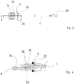
- zeigt das elektrische Anschlusskabel in einer Seitenansicht.
- Figur 3
- zeigt das elektrische Anschlusskabel in einer Aufsicht.
- Figur 4
- zeigt das elektrische Anschlusskabel im Bereich des Adaptersteckers in einem Querschnitt.
- Figur 5
- zeigt ein Leuchtenmodul in Explosionsdarstellung.
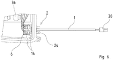
- Figur 6
- zeigt einen Ausschnitt des Leuchtenmoduls in Aufsicht mit montiertem elektrischem Anschlusskabel.
- Bezug nehmend auf
Figur 1 ist der Aufbau eines elektrischen Anschlusskabels dargestellt, welches für ein Leuchtenmodul, wie in derFigur 5 dargestellt ist, vorgesehen ist. - Das elektrische Anschlusskabel umfasst ein leuchtennahes Ende (in
Figur 1 bis 3 links) und ein leuchtenentferntes Ende (inFiguren 1 bis 3 rechts). - Am leuchtennahen Ende ist ein Adapterstecker 2 vorgesehen, welcher ein Steckergehäuse 4 und eine Platine 6 sowie einen O-Ring 8 umfasst. Zur Montage des Adaptersteckers 2 werden zunächst einzelne Adern 10 einer elektrischen Leitung 1 an ersten Kontaktstellen 12 der Platine 6 angelötet. Die ersten elektrischen Kontaktstellen 12 stehen über Leiterbahnen auf der Platine 6 in Verbindung mit zweiten elektrischen Kontaktstellen 14 in Form von Klemmen, in welchen elektrische Leitungen im Leuchtemodul angeklemmt werden können (siehe
Figur 6 ). - Nachdem die Adern 10 an den ersten Kontaktstellen 12 der Platine 6 angelötet sind, wird die elektrische Leitung 1 durch das Steckergehäuse 4 hindurch geführt und die Platine in einen Einschubschlitz des Steckergehäuses 4 eingeschoben. An den Längsseiten der Platine 6 sind Rastvorsprünge 16 vorgesehen, welche in seitlichen Fenstern 17 im Einschubschlitz des Gehäusesteckers 4 einrasten. In diesem Zustand hält der Adapterstecker 4 bereits zusammen. Zur Abdichtung und Fixierung des Adaptersteckers 2 wird eine Vergussmasse im Bereich der Platine 6 und des Steckergehäuses 4 aufgebracht, wie durch den schraffierten Bereich 18 in
Figur 4 dargestellt. Die Vergussmasse 18 hält nicht nur die Platine 6 an dem Steckergehäuse 4 fest, sondern sorgt außerdem für eine Abdichtung, so dass keine Feuchtigkeit und/oder kein Gas durch den Adapterstecker 4 selbst hindurchdringen kann. - Das Steckergehäuse 4 weist ferner einen Flansch 20 auf, der sich in einer Ebene senkrecht zur Längserstreckung der elektrischen Leitung 1 erstreckt. Der Flansch 20 ist dafür bestimmt, mit dem O-Ring 8 zusammen an dem Umfang einer Öffnung 22 in dem Leuchtenmodul anzuliegen. Wie mit dem Pfeil in
Figur 5 dargestellt, wird dazu der Adapterstecker 2 in die Öffnung 22 des Leuchtenmoduls eingeschoben. Der O-Ring 8 wird dabei zwischen dem Flansch und der äußeren Wand des Leuchtenmoduls eingeklemmt, so dass eine Dichtung erzielt wird. An der in Richtung zum leuchtenentfernten Ende weisenden Seite des Flansches sind zwei Pins 24 vorgesehen, an denen der Adapterstecker durch einen Roboter leicht ergriffen werden kann, um ihn in die Öffnung 22 des Leuchtenmoduls automatisch einzufügen. - Der Adapterstecker 2 weist im Bereich des Steckergehäuses 4 Rastvorsprünge 26 auf, welche auf der Innenseite des Leuchtenmoduls hinter der Öffnung 22 einrasten. Dadurch wird der Adapterstecker 2 mechanisch in der Öffnung 22 gehalten.
- Nachdem der Adapterstecker 2 in dem Leuchtenmodul montiert ist, können auf der Innenseite elektrische Leitungen an die Anschlussklemmen der zweiten Kontaktstellen 14 angeschlossen werden, wie in
Figur 6 gezeigt ist. Da die Anschlussklemmen den Draht gleichzeitig elektrisch kontaktieren und mechanisch halten, kann auch dieser Anschluss automatisiert durch einen Roboter vorgenommen werden. - An dem dem Leuchtenmodul entgegensetzten Ende des elektrischen Anschlusskabels ist ein weiterer Stecker 30 vorgesehen, um das Leuchtenmodul an eine elektrische Stromversorgung anzuschließen. Vorzugsweise ist ein Stecker 30 vorgesehen, bei welchem elektrische Pins des Steckers 30 direkt an die Adern 10 der elektrischen Leitung 1 angekrimpt werden und ein Kunststoffgehäuse über die elektrischen Pins geschoben wird.
- Im Inneren des Leuchtenmoduls ist eine Platine 34 vorgesehen, auf der eine Vielzahl von Leuchtmitteln in Form von LEDs angebracht sind. Oberhalb der LEDs sind Linsenelemente 31 in einer Ebene angeordnet, die auf der Platine 34 befestigt werden. Das Leuchtenmodul wird von der Lichtaustrittsseite des Moduls durch eine transparente Abdeckung 38 verschlossen.
-
- 1
- Elektrische Leitung
- 2
- Adapterstecker
- 4
- Gehäusestecker
- 6
- Platine
- 8
- O-Ring
- 10
- Ader der elektrischen Anschlussleitung
- 12
- Erste Kontaktstelle
- 14
- Zweite Kontaktstelle, insbesondere mit Anschlussklemme
- 16
- Rastvorsprünge an der Platine
- 17
- Fenster im Steckgehäuse
- 18
- Vergussmasse
- 20
- Flansch
- 22
- Öffnung im Leuchtenmodul
- 24
- Pin
- 26
- Rastmittel im Steckergehäuse
- 30
- Stecker
- 34
- Platine mit Leuchtmitteln
- 36
- Linsenelemente
- 38
- transparente Abdeckung des Leuchtenmoduls
Claims (11)
- Elektrische Anschlussleitung für die Montage in einer Öffnung (22) eines Leuchtenmoduls, wobei die Anschlussleitung Folgendes umfasst:eine elektrische Leitung (1) mit einem leuchtennahen Ende und einem leuchtenentfernten Ende; undeinen Adapterstecker (2) an dem leuchtennahen Ende der elektrischen Leitung,wobei der Adaptersteckereine Platine (6), die wenigstens eine erste Kontaktstelle (12) aufweist, an der eine Ader (10) der elektrischen Leitung angeschlossen ist, und wenigstens eine zweite Kontaktstelle (14) aufweist, die über die Platine (6) in elektrischer Verbindung mit der ersten Kontaktstelle (12) steht und an der eine elektrische Leitung in einem Inneren des Leuchtenmoduls anschließbar ist,sowie ein Steckergehäuse (4) umfasst, welches mit der Platine (6) durch ein Vergussmaterial (18) verbunden ist und das Mittel zur Befestigung des Adaptersteckers (2) in der Öffnung des Leuchtenmoduls aufweist, wobei das Vergussmaterial (18) die Platine und die wenigstens eine Ader mit dem Steckergehäuse abdichtet,wobei das Steckergehäuse (4) einen Einschubschlitz aufweist, in welchem die Platine (6) eingeschoben ist, dadurch gekennzeichnet, dass die Platine (6) und das Steckergehäuse (4) Rastmittel (16, 17) aufweisen, und die Platine (6) in dem Einschubschlitz des Steckergehäuses (4) vor einem Aufbringen des Vergussmaterials (18) eingerastet ist.
- Elektrische Anschlussleitung nach Anspruch 1, wobei das Steckergehäuse einen Flansch (20) aufweist, welcher im am Leuchtenmodul montierten Zustand des Anschlusskabels an einem Umfang der Öffnung (12) des Leuchtenmoduls von einer Außen- oder Innenseite des Leuchtenmoduls anliegt.
- Elektrisches Anschlusskabel nach einem der vorhergehenden Ansprüche, wobei der Adapterstecker (2) eine Dichtung (8) aufweist, welche den Adapterstecker (2) zu einer Innen- oder Außenseite des Leuchtenmoduls abdichtet, insbesondere bei Rückbezug auf Anspruch 2 einen O-Ring (8), welcher zwischen dem Flansch (20) und der Außen- oder Innenseite des Leuchtengehäuses liegt.
- Elektrische Anschlussleitung nach einem der vorhergehenden Ansprüche, wobei die Mittel zur Befestigung des Adaptersteckers in der Öffnung Rastmittel (26) umfassen, welche in einem Bereich der Öffnung (22) des Leuchtenmoduls einrastbar sind.
- Elektrische Anschlussleitung nach einem der vorhergehenden Ansprüche, wobei die wenigstens eine zweite Kontaktstelle (14) eine Anschlussklemme umfasst.
- Elektrische Anschlussleitung nach einem der vorhergehenden Ansprüche, wobei die wenigstens eine erste Kontaktstelle (12) eine Lötstelle umfasst.
- Elektrische Anschlussleitung nach einem der vorhergehenden Ansprüche, wobei an dem leuchtenentfernten Ende der elektrischen Leitung ein Stecker (30) zur Verbindung mit einem elektrischen Vorschaltgerät vorgesehen ist.
- Elektrische Anschlussleitung nach Anspruch 7, wobei der Stecker (30) an dem leuchtenentfernten Ende durch Krimpen an der wenigstens einen Ader (10) der elektrischen Leitung (1) befestigt und elektrisch kontaktiert ist.
- Leuchtenmodul umfassend eine elektrische Anschlussleitung nach einem der vorhergehenden Ansprüche sowie ein Modulgehäuse, welches eine Öffnung (22) aufweist, in welche der Adapterstecker montiert ist, und eine Platine (34), auf welcher Leuchtmittel angeordnet sind, wobei die Platine (34) mit den Leuchtmitteln elektrisch mit der wenigstens einen zweiten Kontaktstelle (14) des Adaptersteckers verbunden ist.
- Leuchtenmodul nach Anspruch 9 wobei die Leuchtmittel eine oder mehrere LEDs umfassen.
- Leuchtenmodul nach Anspruch 9 oder 10, wobei das Leuchtenmodul feuchtigkeits- und/oder gasdicht ist.
Applications Claiming Priority (1)
| Application Number | Priority Date | Filing Date | Title |
|---|---|---|---|
| DE102014116387.7A DE102014116387B4 (de) | 2014-11-10 | 2014-11-10 | Elektrisches Anschlusskabel für ein Leuchtenmodul |
Publications (2)
| Publication Number | Publication Date |
|---|---|
| EP3018780A1 EP3018780A1 (de) | 2016-05-11 |
| EP3018780B1 true EP3018780B1 (de) | 2020-07-01 |
Family
ID=54477902
Family Applications (1)
| Application Number | Title | Priority Date | Filing Date |
|---|---|---|---|
| EP15193430.4A Active EP3018780B1 (de) | 2014-11-10 | 2015-11-06 | Elektrisches anschlusskabel für leuchtenmodul |
Country Status (2)
| Country | Link |
|---|---|
| EP (1) | EP3018780B1 (de) |
| DE (1) | DE102014116387B4 (de) |
Families Citing this family (1)
| Publication number | Priority date | Publication date | Assignee | Title |
|---|---|---|---|---|
| DE102018002076B3 (de) | 2018-03-15 | 2019-07-11 | Siegfried Binder | Durchführung von stromführenden leitungen zur hermetischen trennung zweier medien und verfahren zur herstellung derselben |
Citations (1)
| Publication number | Priority date | Publication date | Assignee | Title |
|---|---|---|---|---|
| GB2323483A (en) * | 1996-12-12 | 1998-09-23 | Whitaker Corp | Electrical connector assembly |
Family Cites Families (5)
| Publication number | Priority date | Publication date | Assignee | Title |
|---|---|---|---|---|
| DE10350724B4 (de) * | 2003-10-30 | 2015-02-05 | Hottinger Baldwin Messtechnik Gmbh | Kabelanschlusseinheit für technische Geräte |
| DE102010033297A1 (de) * | 2010-08-04 | 2012-02-09 | Hella Kgaa Hueck & Co. | Beleuchtungsvorrichtung und Dichtelement hierfür |
| DE102011075032A1 (de) | 2011-04-29 | 2012-10-31 | Osram Ag | Leuchtvorrichtung und Verfahren zum Herstellen einer Leuchtvorrichtung |
| DE102011052576B3 (de) * | 2011-08-11 | 2012-12-06 | Hella Kgaa Hueck & Co. | Elektrische Vorrichtung mit Dichtelement, Dichtelement für eine elektrische Vorrichtung und Verfahren zum Abdichten eines Gehäuses |
| DE202011051749U1 (de) * | 2011-10-25 | 2011-11-15 | Alfons Rüschenbaum GmbH | Anschlussvorrichtung zum Anschluss einer Anzahl von LED-Leuchtmitteln an ein LED-Treibermittel mit Konstantstromspeisung |
-
2014
- 2014-11-10 DE DE102014116387.7A patent/DE102014116387B4/de not_active Expired - Fee Related
-
2015
- 2015-11-06 EP EP15193430.4A patent/EP3018780B1/de active Active
Patent Citations (1)
| Publication number | Priority date | Publication date | Assignee | Title |
|---|---|---|---|---|
| GB2323483A (en) * | 1996-12-12 | 1998-09-23 | Whitaker Corp | Electrical connector assembly |
Also Published As
| Publication number | Publication date |
|---|---|
| EP3018780A1 (de) | 2016-05-11 |
| DE102014116387B4 (de) | 2016-10-27 |
| DE102014116387A1 (de) | 2016-05-12 |
Similar Documents
| Publication | Publication Date | Title |
|---|---|---|
| DE202017101060U1 (de) | Steckverbinder, insbesondere für eine Hochstromanwendung | |
| DE202010018447U1 (de) | Anschlusssystem für ein Netzteil und Netzteil | |
| EP3266076A1 (de) | Verfahren zur montage eines winkelsteckverbinders | |
| DE102010002565B3 (de) | Anschlussvorrichtung für eiin Solarmodul | |
| DE102014100142A1 (de) | Hochwasserfeste Steckerkonstruktion für eine widerstandsarme Leitung zwischen Erdstift und Gehäuse | |
| DE3742320A1 (de) | Ventilblock | |
| DE10351677A1 (de) | Mehrfachscheibe mit einer Leitungsdurchführung | |
| EP3097609A1 (de) | Vorrichtung zum kontaktieren von elektrischen leitern, sowie leuchtsystem | |
| WO1999066606A1 (de) | Durchführungsadapter für schaltschränke | |
| DE102008023108A1 (de) | Kantenverbinder für ein Solarmodul, Steckverbinder zur Verbindung mit dem Kantenverbinder sowie Solarmodul mit einem derartigen Kantenverbinder | |
| WO2007113030A1 (de) | Anschlussmodul zum anschluss einer steuereinheit oder dergleichen an eine antriebseinheit | |
| DE102012216383A1 (de) | Hülsendichtung | |
| EP2603957B1 (de) | Rückseitige anbindung von led-modulen | |
| EP4324052B1 (de) | Kabelanschlusseinheit für eine anschlussdose | |
| DE202009016970U1 (de) | Verbindungsvorrichtung | |
| EP1667285A2 (de) | Leitungshalter | |
| DE102014116387B4 (de) | Elektrisches Anschlusskabel für ein Leuchtenmodul | |
| DE102005040941A1 (de) | Dichtungselement für Flexible Flat Cable (FFC), FPC und andere flache Leitungen mit und ohne Rundleiter | |
| DE102012102849A1 (de) | Befestigung und Abdichtung eines Steckanschlussmoduls in einer Gehäusewandung | |
| DE102013007815B4 (de) | Schwenkbarer Verbinder und Kontaktierungsverfahren | |
| EP2386125B1 (de) | Solarpaneel und verfahren zu dessen herstellung | |
| DE10350724B4 (de) | Kabelanschlusseinheit für technische Geräte | |
| DE20319759U1 (de) | Anschlussteil für ein Schaltgerät, Schaltungsmodul und daraus zusammengesetzte Zwischenbaugruppe | |
| DE102009053015A1 (de) | Anschlussmodul für Solarpanele mit vorgefertigtem Anschluss-Strang | |
| DE102014115644A1 (de) | Leuchte mit Kontaktierungsmodul |
Legal Events
| Date | Code | Title | Description |
|---|---|---|---|
| PUAI | Public reference made under article 153(3) epc to a published international application that has entered the european phase |
Free format text: ORIGINAL CODE: 0009012 |
|
| AK | Designated contracting states |
Kind code of ref document: A1 Designated state(s): AL AT BE BG CH CY CZ DE DK EE ES FI FR GB GR HR HU IE IS IT LI LT LU LV MC MK MT NL NO PL PT RO RS SE SI SK SM TR |
|
| AX | Request for extension of the european patent |
Extension state: BA ME |
|
| STAA | Information on the status of an ep patent application or granted ep patent |
Free format text: STATUS: REQUEST FOR EXAMINATION WAS MADE |
|
| 17P | Request for examination filed |
Effective date: 20161103 |
|
| RBV | Designated contracting states (corrected) |
Designated state(s): AL AT BE BG CH CY CZ DE DK EE ES FI FR GB GR HR HU IE IS IT LI LT LU LV MC MK MT NL NO PL PT RO RS SE SI SK SM TR |
|
| STAA | Information on the status of an ep patent application or granted ep patent |
Free format text: STATUS: EXAMINATION IS IN PROGRESS |
|
| 17Q | First examination report despatched |
Effective date: 20180626 |
|
| GRAP | Despatch of communication of intention to grant a patent |
Free format text: ORIGINAL CODE: EPIDOSNIGR1 |
|
| STAA | Information on the status of an ep patent application or granted ep patent |
Free format text: STATUS: GRANT OF PATENT IS INTENDED |
|
| RIC1 | Information provided on ipc code assigned before grant |
Ipc: H02G 15/013 20060101AFI20191213BHEP Ipc: F21V 5/00 20180101ALN20191213BHEP Ipc: F21V 23/06 20060101ALN20191213BHEP |
|
| INTG | Intention to grant announced |
Effective date: 20200120 |
|
| RAP1 | Party data changed (applicant data changed or rights of an application transferred) |
Owner name: SITECO GMBH |
|
| GRAS | Grant fee paid |
Free format text: ORIGINAL CODE: EPIDOSNIGR3 |
|
| GRAA | (expected) grant |
Free format text: ORIGINAL CODE: 0009210 |
|
| STAA | Information on the status of an ep patent application or granted ep patent |
Free format text: STATUS: THE PATENT HAS BEEN GRANTED |
|
| RBV | Designated contracting states (corrected) |
Designated state(s): AL AT BE BG CH CY CZ DK EE ES FI FR GB GR HR HU IE IS IT LI LT LU LV MC MK MT NL NO PL PT RO RS SE SI SK SM TR |
|
| REG | Reference to a national code |
Ref country code: DE Ref legal event code: R108 |
|
| AK | Designated contracting states |
Kind code of ref document: B1 Designated state(s): AL AT BE BG CH CY CZ DK EE ES FI FR GB GR HR HU IE IS IT LI LT LU LV MC MK MT NL NO PL PT RO RS SE SI SK SM TR |
|
| REG | Reference to a national code |
Ref country code: CH Ref legal event code: EP Ref country code: AT Ref legal event code: REF Ref document number: 1287049 Country of ref document: AT Kind code of ref document: T Effective date: 20200715 |
|
| REG | Reference to a national code |
Ref country code: IE Ref legal event code: FG4D Free format text: LANGUAGE OF EP DOCUMENT: GERMAN |
|
| REG | Reference to a national code |
Ref country code: CH Ref legal event code: NV Representative=s name: ISLER AND PEDRAZZINI AG, CH |
|
| REG | Reference to a national code |
Ref country code: LT Ref legal event code: MG4D |
|
| PG25 | Lapsed in a contracting state [announced via postgrant information from national office to epo] |
Ref country code: BG Free format text: LAPSE BECAUSE OF FAILURE TO SUBMIT A TRANSLATION OF THE DESCRIPTION OR TO PAY THE FEE WITHIN THE PRESCRIBED TIME-LIMIT Effective date: 20201001 |
|
| REG | Reference to a national code |
Ref country code: NL Ref legal event code: MP Effective date: 20200701 |
|
| PG25 | Lapsed in a contracting state [announced via postgrant information from national office to epo] |
Ref country code: FI Free format text: LAPSE BECAUSE OF FAILURE TO SUBMIT A TRANSLATION OF THE DESCRIPTION OR TO PAY THE FEE WITHIN THE PRESCRIBED TIME-LIMIT Effective date: 20200701 Ref country code: HR Free format text: LAPSE BECAUSE OF FAILURE TO SUBMIT A TRANSLATION OF THE DESCRIPTION OR TO PAY THE FEE WITHIN THE PRESCRIBED TIME-LIMIT Effective date: 20200701 Ref country code: SE Free format text: LAPSE BECAUSE OF FAILURE TO SUBMIT A TRANSLATION OF THE DESCRIPTION OR TO PAY THE FEE WITHIN THE PRESCRIBED TIME-LIMIT Effective date: 20200701 Ref country code: ES Free format text: LAPSE BECAUSE OF FAILURE TO SUBMIT A TRANSLATION OF THE DESCRIPTION OR TO PAY THE FEE WITHIN THE PRESCRIBED TIME-LIMIT Effective date: 20200701 Ref country code: GR Free format text: LAPSE BECAUSE OF FAILURE TO SUBMIT A TRANSLATION OF THE DESCRIPTION OR TO PAY THE FEE WITHIN THE PRESCRIBED TIME-LIMIT Effective date: 20201002 Ref country code: NO Free format text: LAPSE BECAUSE OF FAILURE TO SUBMIT A TRANSLATION OF THE DESCRIPTION OR TO PAY THE FEE WITHIN THE PRESCRIBED TIME-LIMIT Effective date: 20201001 Ref country code: CZ Free format text: LAPSE BECAUSE OF FAILURE TO SUBMIT A TRANSLATION OF THE DESCRIPTION OR TO PAY THE FEE WITHIN THE PRESCRIBED TIME-LIMIT Effective date: 20200701 Ref country code: PT Free format text: LAPSE BECAUSE OF FAILURE TO SUBMIT A TRANSLATION OF THE DESCRIPTION OR TO PAY THE FEE WITHIN THE PRESCRIBED TIME-LIMIT Effective date: 20201102 Ref country code: LT Free format text: LAPSE BECAUSE OF FAILURE TO SUBMIT A TRANSLATION OF THE DESCRIPTION OR TO PAY THE FEE WITHIN THE PRESCRIBED TIME-LIMIT Effective date: 20200701 |
|
| PG25 | Lapsed in a contracting state [announced via postgrant information from national office to epo] |
Ref country code: PL Free format text: LAPSE BECAUSE OF FAILURE TO SUBMIT A TRANSLATION OF THE DESCRIPTION OR TO PAY THE FEE WITHIN THE PRESCRIBED TIME-LIMIT Effective date: 20200701 Ref country code: LV Free format text: LAPSE BECAUSE OF FAILURE TO SUBMIT A TRANSLATION OF THE DESCRIPTION OR TO PAY THE FEE WITHIN THE PRESCRIBED TIME-LIMIT Effective date: 20200701 Ref country code: RS Free format text: LAPSE BECAUSE OF FAILURE TO SUBMIT A TRANSLATION OF THE DESCRIPTION OR TO PAY THE FEE WITHIN THE PRESCRIBED TIME-LIMIT Effective date: 20200701 Ref country code: IS Free format text: LAPSE BECAUSE OF FAILURE TO SUBMIT A TRANSLATION OF THE DESCRIPTION OR TO PAY THE FEE WITHIN THE PRESCRIBED TIME-LIMIT Effective date: 20201101 |
|
| PG25 | Lapsed in a contracting state [announced via postgrant information from national office to epo] |
Ref country code: NL Free format text: LAPSE BECAUSE OF FAILURE TO SUBMIT A TRANSLATION OF THE DESCRIPTION OR TO PAY THE FEE WITHIN THE PRESCRIBED TIME-LIMIT Effective date: 20200701 |
|
| PG25 | Lapsed in a contracting state [announced via postgrant information from national office to epo] |
Ref country code: SM Free format text: LAPSE BECAUSE OF FAILURE TO SUBMIT A TRANSLATION OF THE DESCRIPTION OR TO PAY THE FEE WITHIN THE PRESCRIBED TIME-LIMIT Effective date: 20200701 Ref country code: RO Free format text: LAPSE BECAUSE OF FAILURE TO SUBMIT A TRANSLATION OF THE DESCRIPTION OR TO PAY THE FEE WITHIN THE PRESCRIBED TIME-LIMIT Effective date: 20200701 Ref country code: EE Free format text: LAPSE BECAUSE OF FAILURE TO SUBMIT A TRANSLATION OF THE DESCRIPTION OR TO PAY THE FEE WITHIN THE PRESCRIBED TIME-LIMIT Effective date: 20200701 Ref country code: IT Free format text: LAPSE BECAUSE OF FAILURE TO SUBMIT A TRANSLATION OF THE DESCRIPTION OR TO PAY THE FEE WITHIN THE PRESCRIBED TIME-LIMIT Effective date: 20200701 Ref country code: DK Free format text: LAPSE BECAUSE OF FAILURE TO SUBMIT A TRANSLATION OF THE DESCRIPTION OR TO PAY THE FEE WITHIN THE PRESCRIBED TIME-LIMIT Effective date: 20200701 |
|
| PLBE | No opposition filed within time limit |
Free format text: ORIGINAL CODE: 0009261 |
|
| STAA | Information on the status of an ep patent application or granted ep patent |
Free format text: STATUS: NO OPPOSITION FILED WITHIN TIME LIMIT |
|
| PG25 | Lapsed in a contracting state [announced via postgrant information from national office to epo] |
Ref country code: AL Free format text: LAPSE BECAUSE OF FAILURE TO SUBMIT A TRANSLATION OF THE DESCRIPTION OR TO PAY THE FEE WITHIN THE PRESCRIBED TIME-LIMIT Effective date: 20200701 |
|
| 26N | No opposition filed |
Effective date: 20210406 |
|
| PG25 | Lapsed in a contracting state [announced via postgrant information from national office to epo] |
Ref country code: MC Free format text: LAPSE BECAUSE OF FAILURE TO SUBMIT A TRANSLATION OF THE DESCRIPTION OR TO PAY THE FEE WITHIN THE PRESCRIBED TIME-LIMIT Effective date: 20200701 Ref country code: SK Free format text: LAPSE BECAUSE OF FAILURE TO SUBMIT A TRANSLATION OF THE DESCRIPTION OR TO PAY THE FEE WITHIN THE PRESCRIBED TIME-LIMIT Effective date: 20200701 |
|
| PG25 | Lapsed in a contracting state [announced via postgrant information from national office to epo] |
Ref country code: LU Free format text: LAPSE BECAUSE OF NON-PAYMENT OF DUE FEES Effective date: 20201106 |
|
| REG | Reference to a national code |
Ref country code: BE Ref legal event code: MM Effective date: 20201130 |
|
| PG25 | Lapsed in a contracting state [announced via postgrant information from national office to epo] |
Ref country code: SI Free format text: LAPSE BECAUSE OF FAILURE TO SUBMIT A TRANSLATION OF THE DESCRIPTION OR TO PAY THE FEE WITHIN THE PRESCRIBED TIME-LIMIT Effective date: 20200701 |
|
| PG25 | Lapsed in a contracting state [announced via postgrant information from national office to epo] |
Ref country code: IE Free format text: LAPSE BECAUSE OF NON-PAYMENT OF DUE FEES Effective date: 20201106 |
|
| PG25 | Lapsed in a contracting state [announced via postgrant information from national office to epo] |
Ref country code: TR Free format text: LAPSE BECAUSE OF FAILURE TO SUBMIT A TRANSLATION OF THE DESCRIPTION OR TO PAY THE FEE WITHIN THE PRESCRIBED TIME-LIMIT Effective date: 20200701 Ref country code: MT Free format text: LAPSE BECAUSE OF FAILURE TO SUBMIT A TRANSLATION OF THE DESCRIPTION OR TO PAY THE FEE WITHIN THE PRESCRIBED TIME-LIMIT Effective date: 20200701 Ref country code: CY Free format text: LAPSE BECAUSE OF FAILURE TO SUBMIT A TRANSLATION OF THE DESCRIPTION OR TO PAY THE FEE WITHIN THE PRESCRIBED TIME-LIMIT Effective date: 20200701 |
|
| PG25 | Lapsed in a contracting state [announced via postgrant information from national office to epo] |
Ref country code: MK Free format text: LAPSE BECAUSE OF FAILURE TO SUBMIT A TRANSLATION OF THE DESCRIPTION OR TO PAY THE FEE WITHIN THE PRESCRIBED TIME-LIMIT Effective date: 20200701 |
|
| PG25 | Lapsed in a contracting state [announced via postgrant information from national office to epo] |
Ref country code: BE Free format text: LAPSE BECAUSE OF NON-PAYMENT OF DUE FEES Effective date: 20201130 |
|
| PGFP | Annual fee paid to national office [announced via postgrant information from national office to epo] |
Ref country code: GB Payment date: 20231123 Year of fee payment: 9 |
|
| PGFP | Annual fee paid to national office [announced via postgrant information from national office to epo] |
Ref country code: FR Payment date: 20231122 Year of fee payment: 9 Ref country code: CH Payment date: 20231202 Year of fee payment: 9 Ref country code: AT Payment date: 20231117 Year of fee payment: 9 |
|
| REG | Reference to a national code |
Ref country code: CH Ref legal event code: PL |
|
| REG | Reference to a national code |
Ref country code: AT Ref legal event code: MM01 Ref document number: 1287049 Country of ref document: AT Kind code of ref document: T Effective date: 20241106 Ref country code: CH Ref legal event code: PL |
|
| GBPC | Gb: european patent ceased through non-payment of renewal fee |
Effective date: 20241106 |
|
| PG25 | Lapsed in a contracting state [announced via postgrant information from national office to epo] |
Ref country code: CH Free format text: LAPSE BECAUSE OF NON-PAYMENT OF DUE FEES Effective date: 20241130 |
|
| PG25 | Lapsed in a contracting state [announced via postgrant information from national office to epo] |
Ref country code: AT Free format text: LAPSE BECAUSE OF NON-PAYMENT OF DUE FEES Effective date: 20241106 |
|
| PG25 | Lapsed in a contracting state [announced via postgrant information from national office to epo] |
Ref country code: GB Free format text: LAPSE BECAUSE OF NON-PAYMENT OF DUE FEES Effective date: 20241106 |
|
| PG25 | Lapsed in a contracting state [announced via postgrant information from national office to epo] |
Ref country code: FR Free format text: LAPSE BECAUSE OF NON-PAYMENT OF DUE FEES Effective date: 20241130 |