EP3019301B1 - Tarière ayant un revêtement laser et/ou un traitement thermique par laser, et procédé associé - Google Patents
Tarière ayant un revêtement laser et/ou un traitement thermique par laser, et procédé associé Download PDFInfo
- Publication number
- EP3019301B1 EP3019301B1 EP14822352.2A EP14822352A EP3019301B1 EP 3019301 B1 EP3019301 B1 EP 3019301B1 EP 14822352 A EP14822352 A EP 14822352A EP 3019301 B1 EP3019301 B1 EP 3019301B1
- Authority
- EP
- European Patent Office
- Prior art keywords
- laser
- flight
- auger
- base material
- hardness
- Prior art date
- Legal status (The legal status is an assumption and is not a legal conclusion. Google has not performed a legal analysis and makes no representation as to the accuracy of the status listed.)
- Active
Links
Images




Classifications
-
- B—PERFORMING OPERATIONS; TRANSPORTING
- B65—CONVEYING; PACKING; STORING; HANDLING THIN OR FILAMENTARY MATERIAL
- B65G—TRANSPORT OR STORAGE DEVICES, e.g. CONVEYORS FOR LOADING OR TIPPING, SHOP CONVEYOR SYSTEMS OR PNEUMATIC TUBE CONVEYORS
- B65G33/00—Screw or rotary spiral conveyors
- B65G33/08—Screw or rotary spiral conveyors for fluent solid materials
-
- B—PERFORMING OPERATIONS; TRANSPORTING
- B65—CONVEYING; PACKING; STORING; HANDLING THIN OR FILAMENTARY MATERIAL
- B65G—TRANSPORT OR STORAGE DEVICES, e.g. CONVEYORS FOR LOADING OR TIPPING, SHOP CONVEYOR SYSTEMS OR PNEUMATIC TUBE CONVEYORS
- B65G33/00—Screw or rotary spiral conveyors
- B65G33/24—Details
- B65G33/26—Screws
- B65G33/265—Screws with a continuous helical surface
Definitions
- This invention generally relates to the field of augers and more specifically to agricultural augers.
- Augers are well known in the art and have been employed in many industries over the years. Augers have proven particularly useful in the field of agriculture. For example augers are employed in combines, transport tube augers, and grain bins to name just a few of the many agricultural uses for augers. Examples of such agricultural augers are shown for example in U.S. Patent Number 4,842,126 which discloses the preamble of claim 1 and European Patent EP 2200914 .
- augers are used to move fungible materials like grain from one location to another.
- the material being moved by the augers is hard and abrasive.
- the hard material for example, dried corn, is abrasive and erodes the flight of the auger. Over time, the erosion of the auger flight diminishes the flight's and thereby the auger's performance and efficiency.
- Such wear may cause the auger or even the equipment employing the auger to be replaced. Further, in some instances such worn auger flights can damage the very material that it intended to move.
- the auger's loss of performance can be attributable to at least two types of erosion.
- the first type of auger erosion is found on the top edge of the flighting.
- such erosion creates an undesirable gap between the auger flight and the tube in which the auger turns.
- the increased gap allows the conveyed material to slip past the auger flight, not be moved up the tube and thereby result in decreased efficiency.
- the reduced efficiency of the auger system can eventually lead to the system becoming inoperable.
- a second example of erosion is attributable to that which occurs along the face of the flighting. This type of erosion typically takes place along the outer periphery of the flight face and can eventually lead to large segments of flighting becoming detached from the auger.
- the present invention is directed toward increasing the life span of such augers.
- the present invention achieves this by providing a fabricated agricultural auger according to claim 1 and a method of hardening a fabricated agricultural auger according to claim 8.
- a fabricated agricultural auger for conveying grain material includes a shaft that is adapted to rotate about a central axis.
- a flight of sheet steel extends and spirals about the shaft.
- the flight includes a base material of a first hardness.
- the flight is separately fabricated from the shaft and is welded thereto.
- a laser treated material is formed on or into the base material along a portion of the flight.
- the laser treated material comprises a second hardness greater than the first hardness.
- the laser treated material comprises laser cladding including a clad material different than the base material.
- the clad material is laid along an outermost circumference of the flight and forms a radial outermost peripheral contact surface.
- the fabricated agricultural auger has a predetermined inlet end and a predetermined outlet end.
- the flight includes an upstream face that faces toward the outlet end and a downstream face that faces toward the inlet end. Rotation of the auger conveys material from the inlet end to the outlet end.
- An outer circumference edge of base material extends between the upstream face and the downstream face and the laser clad is formed along the outer circumference edge.
- the laser treated material comprises laser cladding and may comprise laser hardening.
- the base material can be steel and the laser treated material may comprise a laser hardened layer formed integrally with an outer surface of the base material.
- the laser hardened layer may be at least .5 millimeter in depth thickness along the base material.
- the laser hardened layer may be between .5 and 5 millimeters in depth thickness along the base material.
- a cross section thickness of the flight is reduced at treated regions of the laser hardened layer relative to untreated regions of the base material.
- the laser hardened layer is along the upstream face only and the downstream face only has an outer untreated surface of the base material.
- An embodiment may further include an outer treated region of the laser hardened layer along an outer radial periphery of the flight.
- the inner untreated region of an outer surface of the base material may be disposed radially between the outer treated region and the shaft.
- the outer treated region can be between 5 % and 35% of a radial span of the flight.
- the base material can have a hardness of less than 25 in Rockwell C Scale hardness.
- the laser treated material may have a hardness between 30 and 62 in Rockwell C Scale hardness.
- the flight faces are free of laser clad.
- the clad material may include at least one of the materials comprising: tungsten carbide, chrome carbide, iron carbide, ceramic, and other material having a Vickers scale hardness between HV 1200-3200.
- the laser treated material may comprise laser cladding that includes a clad material different than the base material.
- the base material can be steel and the laser treated material can additionally comprise a laser hardened layer formed integrally with an outer surface of the base material.
- the clad material may can be joined with the laser hardened layer at an outer radial edge thereof.
- the auger includes a shaft adapted to rotate about a central axis.
- a flight of sheet steel is adapted to extend around and spiral about the shaft.
- the flight includes a base material of a first hardness.
- the flight is separately fabricated from the shaft and welded thereto.
- the method includes laser treating a portion of the base material to provide a hardened region to the auger with a second hardness greater than the first hardness.
- the laser treated material comprises laser cladding including a clad material different than the base material.
- the clad material is laid along an outermost circumference of the flight and forms a radial outermost peripheral contact surface.
- the fabricated agricultural auger has a predetermined inlet end and a predetermined outlet end.
- the flight includes an upstream face that faces toward the outlet end and a downstream face that faces toward the inlet end. Rotation of the auger conveys material from the inlet end to the outlet end.
- An outer circumference edge of base material extends between the upstream face and the downstream face and the laser clad is formed along the outer circumference edge.
- the laser treating can include laser cladding a clad material to a region proximate an outermost circumferential surface of the flight.
- the laser treating can include laser hardening an outer surface of the base material to provide a laser hardened layer formed integrally with the base material. The laser treating may be conducted after the flight is secured to the shaft.
- the laser treating may include laser cladding a clad material to a region proximate an outermost circumferential surface of the flight. It can include laser hardening an outer surface of the base material to provide a laser hardened layer formed integrally with the base material.
- the fabricated agricultural auger of the present invention may be included in various agricultural grain handling devices such as transport tube augers, tube augers, combine harvesters or agricultural grain bins that utilize trough augers, horizontal and overhead tube augers as well as free/tubeless augers to name just a few grain handling devices employing the fabricated agricultural grain auger.
- the fabricated agricultural auger of the present invention may be included in an agricultural grain handling device that comprises an agricultural housing that comprises at least one of a grain bin, an auger tube and an auger trough.
- the auger is disposed in the housing.
- an agricultural auger 10 according to an embodiment of the present invention is illustrated.
- the agricultural auger comprises a shaft 14 adapted to rotate about a central axis 16.
- a flight 18 extends spiraling about the shaft 14.
- the flight 18 comprises a base material 20 of a first hardness.
- the base material 20 may be steel but can be comprised of any of the materials commonly used in the manufacture of augers.
- the flight 18 is separately fabricated such as from sheet steel and thereby separated from the shaft 14 that is rod or bar stock.
- the flight can be spirally configured and welded 22 or otherwise secured to the shaft 14. In a welded embodiment as shown in FIG.
- welds or other fastening means 22 are placed at that part of the flight in contact with the shaft.
- the welds 22 are further shown in an exaggerated fashion in FIG 3 . It can be readily appreciated that where the agricultural auger is not fabricated such welds 22 would not be present.
- the flight pitch 60 may be between .25_ and 4 per foot.
- the flight outer diameter may be between 3" and 4" for most agricultural applications.
- the agricultural auger has an inlet end 34 and an outlet end 36. Although illustrated is a preferred embodiment that moves grain from the inlet end 34 to the outlet end 36. It is readily apparent that there are many agricultural uses for an agricultural auger 10 such as grain bins, tube augers or combine harvesters to name just a few examples.
- the material being moved travels along an upstream face 38 of the flight towards the outlet end 36 of the agricultural auger 10.
- the grain traveling along the upstream face of the flight 38 can cause wear to the base material 20 of the flighting 18 along the outer radial periphery 44 of the flight 18 and to the outer circumferential edge 46 of the flight 18.
- the present invention seeks to prevent wear and erosion to the outer radial periphery 44 of the upstream face 38 by applying laser hardening and to the an outermost circumference comprises a circumferential edge 46 of the flight 18 by application of laser cladding.
- the outer radial periphery 44 of the base material 20 of the flight 18 is laser treated to harden the outer radial periphery 44 of the flight 18.
- This laser hardened area comprises a material of second hardness 26 on the upstream face 38 of the flight 18.
- FIG. 2 shows an enlarged view of the untreated downstream face 40 and the upstream face 38 where laser hardening has been applied to the outer radial periphery 44 of the flight 18 leaving a treated laser hardened upstream
- the outer treated region may comprise between 5% and 35% of a radial span 58 of the flight 18 while 100% of the downstream face 40 of the flight makes up a region free of any laser hardening or laser cladding whatsoever.
- Restricting the laser hardening application to the outer radial periphery of the upstream face of the flight 38 and laser cladding the outer circumferential edge 46 of the base material 20 has a fabrication cost benefit of placing laser hardening and/or laser cladding only where erosion occurs.
- Laser cladding and laser hardening are performed with a very shallow heat affected zone. This low heat input process reduces the issues of shape distortion in the flighting where laser hardening and/or cladding are not applied and thus its application does not negatively affect the metallurgical structure of the base material 20.
- FIG. 2 shows in this preferred embodiment that laser cladding 24 has been applied to the outer circumferential edge of the flight 18.
- FIG. 2 shows both laser hardening 26 and laser cladding 24 applied to the flight 18.
- the flight may be that the flight receives only laser cladding on its outer circumferential edge 46 as shown in FIG. 4B . Further, it may be that only that portion of the circumferential edge 46 that abuts the outer radial periphery 44 of the upstream face 38 of the flight 18 and not the entire width of the circumferential edge 46 receives the cladding.
- the laser cladding may be applied to the outer circumferential edge 46 such that it overlaps the edge and resides on the outer radial periphery 44 of the flight 18.
- the overlap portion may extend from the outer circumferential edge 46 for 1 cm but preferably 1 mm onto the outer radial periphery 44 of the flight 18.
- FIG. 3 illustrates an enlarged cross section of the flighting of the preferred embodiment of the agricultural auger 10.
- the shaft 14 is shown.
- the shaft may have a diameter between 0.5 inches and 3 inches and a length between 2 feet and 10 feet with welds 22 that attach the spiraled flighting 18 to the shaft.
- the overall length can be much greater with multiple shafts splined or connected together.
- the cross section thickness 30 of the flighting 18 may be between .03 inches and .75 inches.
- FIG. 3 further illustrates the laser hardened region 26 on the outer radial periphery of the flight 18.
- energy is transmitted to the outer radial periphery 44 of the upstream face 38 of the flight 18 in order to create a hardened layer by metallurgical transformation 26, 28.
- the laser is used as a heat source, and rapidly raises the surface temperature of the material. Heat sinking of the surrounding area provides rapid self-quenching, thus producing a material microstructure that results in a hardened transformation layer 26, 28.
- This treated hardened layer can extend between .5 and 5 millimeters in depth thickness.
- the laser hardening extends to some degree to an area beyond this expressed depth thickness due to heat transfer to the base material 20 as a result of the laser hardening process.
- FIG. 4 shows a cross section of the flight 18 about the radial periphery 44 where laser hardening has been applied and where cladding has been applied to the outer circumferential edge 46.
- the decreased cross sectional thickness CT of the flight 18, due to the reduction in thickness of the laser hardened region 28 treated region, relative to the cross section 30 of the untreated region 32 of the flight 18 is shown.
- the base material 20 may have a hardness less than 25 in Rockwell C Scale hardness while laser hardened area 28 is between .5 and 5 millimeters in depth thickness.
- the laser hardened area can have a higher relative hardness between 30 and 62 in Rockwell C Scale hardness.
- FIGS. 3 and 4 illustrate the clad layer 24 on the outer circumferential edge 46 of the flight 18.
- the cladding may be between 0.5 mm and 5 mmin thickness.
- cladding preferably, it comprises tungsten carbide but may also comprise alternatively titanium carbide, chrome carbide, iron carbide, ceramic, and /or high hardness particles in the range of 1200-2500 on the Vickers scale hardness.
- a finishing process may or may not be employed to the cladding 24 after it is applied to the outer circumferential edge 46 of the flight 18. For example, grinding or other such smoothing operation can be done.
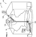
- FIG. 5 illustrates an agricultural grain handling device 74 comprising an agricultural housing 70 comprising an agricultural bin 48 which includes agricultural augers according to embodiments of the present invention in vertical tubeless auger 10A, an overhead tube auger 10B and a trough auger 10C.
- FIG. 6 illustrates an agricultural grain handling device comprising an agricultural housing 70 comprising a combine harvester 50 employing a section of the agricultural auger 10 which includes a bin 68 which further includes an agricultural auger according to an embodiment of the present invention.
- FIG. 7 illustrates an agricultural grain handling device comprising an agricultural housing comprising a tube auger 52 with an embodiment of the present invention.
- FIG. 8 shows a cross section schematic of the agricultural auger 10 within the tube auger 52 of FIG. 7 .
- a clearance 62 between the tube 52 and the outer circumferential edge 46 of the flight 18 with cladding 24 is shown.
- the clearance 62 may be between 0 mm and 20 mm, but typically greater than 1 mm.
- laser hardening and laser cladding provides for a very precise heat treatment pattern, a small transition zone between the hardened area and the unhardened areas, minimal distortion in the fighting and the ability to heat treat the auger 10 as assembled.
- one or the other of the laser heat treatment methods may be employed as desired, that is laser cladding might be employed on one section of auger or to the entire auger while yet another auger may have only laser cladding applied and no laser hardening while still another auger might have both laser cladding and laser hardening applied.
- control of the laser cladding tool can be made to vary the profile of the laser cladding material in both depth and width, that is laser cladding may be applied so as to increase the radial span 58 of the flight 18 and/or the laser cladding may be applied in various widths to span the entire outer circumferential edge 46 of the flight 18, or over only a portion of the circumferential edge 46 or even over the circumferential edge 46 onto the upstream face of the flight 38.
- Application then of the laser cladding tool may include increasing processing speeds to make thinner sections and decreasing processing speeds to make thicker sections.
- the laser cladding tool can be run faster or slower, which correspondently deposits more or less material.
- laser power can be varied through a pass to change the deposition rates.
- the powder flow rate through a laser tool pass can be made to radially decrease or increase the depth of cladding over the outer circumferential edge 46. t.
Landscapes
- Engineering & Computer Science (AREA)
- Mechanical Engineering (AREA)
- Laser Beam Processing (AREA)
Claims (10)
- Tarière agricole usinée destinée à acheminer de la matière en grains, comprenant :un arbre (14) adapté pour tourner autour d'un axe central (16) ;une vis sans fin (18) de tôle d'acier s'étendant et s'enroulant en spirale autour de l'arbre (14), la vis sans fin (18) comprenant un matériau de base (20) d'une première dureté ;dans laquelle la vis sans fin (18) est usinée séparément de l'arbre (14) et soudée (22) à celui-ci ; et caractérisée parun matériau traité au laser formé sur ou dans le matériau de base (20) le long d'une portion de la vis sans fin (18), le matériau traité au laser comprenant une seconde dureté (26) supérieure à la première dureté,dans laquelle le matériau traité au laser comprend un placage laser (24) comportant un matériau de placage différent du matériau de base,dans laquelle le matériau de placage (24) est disposé le long d'une circonférence la plus externe (46) de la vis sans fin (18) et forme une surface de contact périphérique la plus externe radiale,dans laquelle la tarière a une extrémité d'entrée (34) prédéterminée et une extrémité de sortie (36) prédéterminée, la vis sans fin (18) comporte une face amont (38) tournée vers l'extrémité de sortie (36) et une face aval (40) tournée vers l'extrémité d'entrée (34), dans laquelle une rotation de la tarière achemine de la matière de l'extrémité d'entrée (34) à l'extrémité de sortie (36), et un bord circonférentiel externe (46) du matériau de base (20) s'étendant entre la face amont (38) et la face aval (40), dans laquelle le placage laser (24) est formé le long du bord circonférentiel externe (46).
- Tarière agricole usinée selon la revendication 1, dans laquelle le matériau de base (20) est l'acier, et le matériau traité au laser (24) comprend une couche durcie au laser (28) formée solidairement avec une surface externe (44) du matériau de base (20).
- Tarière agricole usinée selon la revendication 2, dans laquelle la couche durcie au laser (24) se situe le long de la face amont (38) uniquement, la face aval (40) ayant uniquement une surface non traitée externe du matériau de base (20).
- Tarière agricole usinée selon la revendication 2, comprenant une région traitée externe de la couche durcie au laser (26) le long d'une périphérie radiale externe (44) de la vis sans fin (18), et une région non traitée interne (32) d'une surface non traitée externe du matériau de base (20) disposée radialement entre la région traitée externe (28) et l'arbre (14).
- Tarière agricole usinée selon la revendication 1, dans laquelle le matériau de base a une dureté inférieure à 25 de dureté Rockwell échelle C, et dans laquelle un matériau traité au laser a une dureté comprise entre 30 et 62 de dureté Rockwell échelle C.
- Tarière agricole usinée selon la revendication 1, dans laquelle le placage (24) est formé le long d'uniquement une portion du bord circonférentiel (46) du matériau de base (20).
- Tarière agricole usinée selon la revendication 6, dans laquelle les faces de vis sans fin sont dépourvues de placage laser.
- Procédé de durcissement d'une tarière agricole usinée comprenant un arbre (14) adapté pour tourner autour d'un axe central (16), et une vis sans fin (18) de tôle d'acier adaptée pour s'étendre et s'enrouler en spirale autour de l'arbre (14), la vis sans fin (18) comprenant un matériau de base (20) d'une première dureté, dans lequel la vis sans fin (18) est usinée séparément de l'arbre (14) et soudée (22) sur celui-ci ; le procédé comprenant :le traitement au laser d'une portion du matériau de base (20) pour fournir une région durcie à la tarière avec une seconde dureté supérieure à la première dureté,ledit traitement au laser comprend le placage laser (24) d'un matériau de placage différent du matériau de base,la disposition du matériau de placage (24) le long d'une circonférence la plus externe (46) de la vis sans fin (18) et la formation d'une surface de contact périphérique la plus externe radiale,la tarière ayant une extrémité d'entrée (34) prédéterminée et une extrémité de sortie (36) prédéterminée, la vis sans fin (18) comporte une face amont (38) tournée vers l'extrémité de sortie (36) et une face aval (40) tournée vers l'extrémité d'entrée (34), de sorte qu'une rotation de la tarière achemine de la matière de l'extrémité d'entrée (34) à l'extrémité de sortie (36), et un bord circonférentiel externe (46) du matériau de base (20) s'étendant entre la face amont (38) et la face aval (40), et le placage laser (24) étant formé le long du bord circonférentiel externe (46).
- Procédé selon la revendication 8, dans lequel ledit traitement au laser comprend le placage laser d'un matériau de placage (24) sur une région proche d'une surface circonférentielle la plus externe (46) de la vis sans fin (18).
- Procédé selon la revendication 8 ou 9, dans lequel ledit traitement au laser comprend le durcissement au laser d'une surface externe du matériau de base (20) pour fournir une couche durcie au laser formée solidairement avec le matériau de base.
Applications Claiming Priority (2)
| Application Number | Priority Date | Filing Date | Title |
|---|---|---|---|
| US13/938,410 US9044820B2 (en) | 2013-07-10 | 2013-07-10 | Auger with laser cladding and/or laser heat treatment and method |
| PCT/US2014/045989 WO2015006470A1 (fr) | 2013-07-10 | 2014-07-09 | Tarière ayant un revêtement laser et/ou un traitement thermique par laser, et procédé associé |
Publications (3)
| Publication Number | Publication Date |
|---|---|
| EP3019301A1 EP3019301A1 (fr) | 2016-05-18 |
| EP3019301A4 EP3019301A4 (fr) | 2017-04-05 |
| EP3019301B1 true EP3019301B1 (fr) | 2021-03-24 |
Family
ID=52276259
Family Applications (1)
| Application Number | Title | Priority Date | Filing Date |
|---|---|---|---|
| EP14822352.2A Active EP3019301B1 (fr) | 2013-07-10 | 2014-07-09 | Tarière ayant un revêtement laser et/ou un traitement thermique par laser, et procédé associé |
Country Status (4)
| Country | Link |
|---|---|
| US (1) | US9044820B2 (fr) |
| EP (1) | EP3019301B1 (fr) |
| CA (1) | CA2916986C (fr) |
| WO (1) | WO2015006470A1 (fr) |
Families Citing this family (5)
| Publication number | Priority date | Publication date | Assignee | Title |
|---|---|---|---|---|
| BE1022112B1 (nl) * | 2014-02-12 | 2016-02-16 | Cnh Industrial Belgium Nv | Oogstmachine |
| DE102015201852B4 (de) * | 2015-02-03 | 2025-06-26 | Krones Ag | Vorrichtung und Verfahren zum Geschwindigkeitsabbau eines Behälterstroms in einer Behälterbehandlungsanlage |
| DE102021109033A1 (de) | 2021-04-12 | 2022-10-13 | Mayer Verwaltungs Gmbh & Co. Kg | Futtermischwagen-Mischschnecke mit Verschleißschutzrand |
| USD981809S1 (en) * | 2022-04-22 | 2023-03-28 | Yajun Ni | Planting device |
| JP7803903B2 (ja) * | 2023-07-31 | 2026-01-21 | 株式会社東芝 | アンテナ装置、及び、その製造方法 |
Citations (8)
| Publication number | Priority date | Publication date | Assignee | Title |
|---|---|---|---|---|
| US4666033A (en) * | 1984-03-16 | 1987-05-19 | Reid Rod B | Auger apparatus |
| DE4130207A1 (de) * | 1991-09-11 | 1993-03-25 | Ind Tech Res Inst | Verfahren zum erzeugen eines metallischen ueberzugs auf einer einspritz-, extrusions- o. dgl. -schraube oder -schnecke |
| DE4233516A1 (de) * | 1991-12-14 | 1993-06-17 | Theysohn Friedrich Fa | Verfahren zur erzeugung einer verschleissfesten schicht |
| US6089334A (en) * | 1998-03-13 | 2000-07-18 | Clark Equipment Company | Invertible auger |
| US20020136083A1 (en) * | 1999-11-17 | 2002-09-26 | Krauss-Maffei Kunststofftechnik Gmbh | Screw for a plastics processing machine, and method of regenerating a screw |
| US20090095214A1 (en) * | 2007-10-10 | 2009-04-16 | Ronald Peter Whitfield | Laser cladding device with an improved nozzle |
| US20120063871A1 (en) * | 2008-03-07 | 2012-03-15 | J. & M. Manufacturing Co., Inc. | Grain cart having a single auger discharge conveyor |
| EP2371205B1 (fr) * | 2010-04-01 | 2012-09-19 | Deere & Company | Moissonneuse-batteuse agricole |
Family Cites Families (13)
| Publication number | Priority date | Publication date | Assignee | Title |
|---|---|---|---|---|
| US3944443A (en) * | 1974-05-01 | 1976-03-16 | Francis Lee Jones | Ultra high temperature chemical reactions with metals |
| US3937317A (en) | 1975-01-02 | 1976-02-10 | Bird Machine Company, Inc. | Components for wear-resistant surfacing helical metal conveyor blades and the so surfaced blades |
| US4416656A (en) * | 1978-02-13 | 1983-11-22 | Pennwalt Corporation | Hard surfacing for a centrifuge conveyor |
| US4516302A (en) * | 1981-07-31 | 1985-05-14 | Ingersoll-Rand Company | Field replaceable screw conveyor inserts |
| US4451302A (en) * | 1982-08-27 | 1984-05-29 | Aluminum Company Of America | Aluminum nitriding by laser |
| US4466533A (en) * | 1982-09-30 | 1984-08-21 | Shwayder Warren M | Blade edge wear clips |
| DE3718779A1 (de) * | 1987-06-04 | 1988-12-22 | Krauss Maffei Ag | Schnecke od. dgl. maschinenteil fuer kunststoffverarbeitende maschinen |
| US4842126A (en) | 1987-06-16 | 1989-06-27 | Mcconnell Allan R | Auger flight section |
| SE468589B (sv) * | 1988-11-10 | 1993-02-15 | Spirac Engineering Ab | Spiraltransportoer |
| US5673618A (en) * | 1996-03-11 | 1997-10-07 | Little; Ramond P. | Screw press flight with wear resistant surface |
| FR2772656A1 (fr) * | 1997-12-22 | 1999-06-25 | Michelin & Cie | Procede de revetement d'une vis d'extrudeuse |
| US6634781B2 (en) * | 2001-01-10 | 2003-10-21 | Saint Gobain Industrial Ceramics, Inc. | Wear resistant extruder screw |
| GB0717952D0 (en) | 2007-09-14 | 2007-10-24 | Agco Do Brasil Com E Ind Stria | Auger conveyors |
-
2013
- 2013-07-10 US US13/938,410 patent/US9044820B2/en active Active
-
2014
- 2014-07-09 EP EP14822352.2A patent/EP3019301B1/fr active Active
- 2014-07-09 WO PCT/US2014/045989 patent/WO2015006470A1/fr not_active Ceased
- 2014-07-09 CA CA2916986A patent/CA2916986C/fr active Active
Patent Citations (8)
| Publication number | Priority date | Publication date | Assignee | Title |
|---|---|---|---|---|
| US4666033A (en) * | 1984-03-16 | 1987-05-19 | Reid Rod B | Auger apparatus |
| DE4130207A1 (de) * | 1991-09-11 | 1993-03-25 | Ind Tech Res Inst | Verfahren zum erzeugen eines metallischen ueberzugs auf einer einspritz-, extrusions- o. dgl. -schraube oder -schnecke |
| DE4233516A1 (de) * | 1991-12-14 | 1993-06-17 | Theysohn Friedrich Fa | Verfahren zur erzeugung einer verschleissfesten schicht |
| US6089334A (en) * | 1998-03-13 | 2000-07-18 | Clark Equipment Company | Invertible auger |
| US20020136083A1 (en) * | 1999-11-17 | 2002-09-26 | Krauss-Maffei Kunststofftechnik Gmbh | Screw for a plastics processing machine, and method of regenerating a screw |
| US20090095214A1 (en) * | 2007-10-10 | 2009-04-16 | Ronald Peter Whitfield | Laser cladding device with an improved nozzle |
| US20120063871A1 (en) * | 2008-03-07 | 2012-03-15 | J. & M. Manufacturing Co., Inc. | Grain cart having a single auger discharge conveyor |
| EP2371205B1 (fr) * | 2010-04-01 | 2012-09-19 | Deere & Company | Moissonneuse-batteuse agricole |
Non-Patent Citations (1)
| Title |
|---|
| RUF: "CARL CLOOS Schweißtechnik GmbH topic", CARL CLOOS SCHWEISSTECHNIK GMBH TOPIC, 24 October 2011 (2011-10-24), http://www.cloos.de/de-en/solutions/ruf/, XP055456227, Retrieved from the Internet <URL:http://static.cloos.de/download/solutions/topic09-06-301573Ruf.pdf> [retrieved on 20180305] * |
Also Published As
| Publication number | Publication date |
|---|---|
| US20150014127A1 (en) | 2015-01-15 |
| WO2015006470A1 (fr) | 2015-01-15 |
| US9044820B2 (en) | 2015-06-02 |
| EP3019301A4 (fr) | 2017-04-05 |
| CA2916986A1 (fr) | 2015-01-15 |
| CA2916986C (fr) | 2017-11-28 |
| EP3019301A1 (fr) | 2016-05-18 |
Similar Documents
| Publication | Publication Date | Title |
|---|---|---|
| US9565803B2 (en) | Machine part with laser cladding and method | |
| CA2916986C (fr) | Tariere ayant un revetement laser et/ou un traitement thermique par laser, et procede associe | |
| US11058061B2 (en) | Transport and processing roller for a harvester | |
| JP6042440B2 (ja) | はめ合わされた層構造を有する通路又はパイプを備えた圧延機コイル形成レイングヘッド | |
| CN102216475B (zh) | 混凝土泵车用混凝土泥浆输送管 | |
| CN115151129B (zh) | 作物处理器和作物处理器制造方法 | |
| US11167333B2 (en) | Coil forming laying head system | |
| US10091938B2 (en) | Toothed crushing disk for a grain processor and method for producing the toothed crushing disk | |
| US20160286725A1 (en) | Crop Processor, Manufacturing Process for a Crop Processor and Crop Processor Roll | |
| CA3057960C (fr) | Lame de coupe et procede de fabrication d'une telle lame | |
| CN113263319A (zh) | 用于螺丝机的处理元件轴的处理元件以及用于制造处理元件的方法 | |
| EP2747912A1 (fr) | Élément d'usure remplaçable pour une tête de positionnement de laminoir | |
| JP2013189301A (ja) | スクリューコンベア |
Legal Events
| Date | Code | Title | Description |
|---|---|---|---|
| PUAI | Public reference made under article 153(3) epc to a published international application that has entered the european phase |
Free format text: ORIGINAL CODE: 0009012 |
|
| 17P | Request for examination filed |
Effective date: 20160204 |
|
| AK | Designated contracting states |
Kind code of ref document: A1 Designated state(s): AL AT BE BG CH CY CZ DE DK EE ES FI FR GB GR HR HU IE IS IT LI LT LU LV MC MK MT NL NO PL PT RO RS SE SI SK SM TR |
|
| AX | Request for extension of the european patent |
Extension state: BA ME |
|
| DAX | Request for extension of the european patent (deleted) | ||
| A4 | Supplementary search report drawn up and despatched |
Effective date: 20170306 |
|
| RIC1 | Information provided on ipc code assigned before grant |
Ipc: B23K 26/352 20140101AFI20170228BHEP Ipc: B65G 33/26 20060101ALI20170228BHEP Ipc: C21D 1/06 20060101ALI20170228BHEP |
|
| STAA | Information on the status of an ep patent application or granted ep patent |
Free format text: STATUS: EXAMINATION IS IN PROGRESS |
|
| 17Q | First examination report despatched |
Effective date: 20180309 |
|
| GRAP | Despatch of communication of intention to grant a patent |
Free format text: ORIGINAL CODE: EPIDOSNIGR1 |
|
| STAA | Information on the status of an ep patent application or granted ep patent |
Free format text: STATUS: GRANT OF PATENT IS INTENDED |
|
| INTG | Intention to grant announced |
Effective date: 20201019 |
|
| GRAS | Grant fee paid |
Free format text: ORIGINAL CODE: EPIDOSNIGR3 |
|
| GRAA | (expected) grant |
Free format text: ORIGINAL CODE: 0009210 |
|
| STAA | Information on the status of an ep patent application or granted ep patent |
Free format text: STATUS: THE PATENT HAS BEEN GRANTED |
|
| AK | Designated contracting states |
Kind code of ref document: B1 Designated state(s): AL AT BE BG CH CY CZ DE DK EE ES FI FR GB GR HR HU IE IS IT LI LT LU LV MC MK MT NL NO PL PT RO RS SE SI SK SM TR |
|
| REG | Reference to a national code |
Ref country code: GB Ref legal event code: FG4D |
|
| REG | Reference to a national code |
Ref country code: CH Ref legal event code: EP |
|
| REG | Reference to a national code |
Ref country code: DE Ref legal event code: R096 Ref document number: 602014076002 Country of ref document: DE |
|
| REG | Reference to a national code |
Ref country code: IE Ref legal event code: FG4D |
|
| REG | Reference to a national code |
Ref country code: AT Ref legal event code: REF Ref document number: 1373993 Country of ref document: AT Kind code of ref document: T Effective date: 20210415 |
|
| REG | Reference to a national code |
Ref country code: LT Ref legal event code: MG9D |
|
| PG25 | Lapsed in a contracting state [announced via postgrant information from national office to epo] |
Ref country code: GR Free format text: LAPSE BECAUSE OF FAILURE TO SUBMIT A TRANSLATION OF THE DESCRIPTION OR TO PAY THE FEE WITHIN THE PRESCRIBED TIME-LIMIT Effective date: 20210625 Ref country code: FI Free format text: LAPSE BECAUSE OF FAILURE TO SUBMIT A TRANSLATION OF THE DESCRIPTION OR TO PAY THE FEE WITHIN THE PRESCRIBED TIME-LIMIT Effective date: 20210324 Ref country code: HR Free format text: LAPSE BECAUSE OF FAILURE TO SUBMIT A TRANSLATION OF THE DESCRIPTION OR TO PAY THE FEE WITHIN THE PRESCRIBED TIME-LIMIT Effective date: 20210324 Ref country code: BG Free format text: LAPSE BECAUSE OF FAILURE TO SUBMIT A TRANSLATION OF THE DESCRIPTION OR TO PAY THE FEE WITHIN THE PRESCRIBED TIME-LIMIT Effective date: 20210624 Ref country code: NO Free format text: LAPSE BECAUSE OF FAILURE TO SUBMIT A TRANSLATION OF THE DESCRIPTION OR TO PAY THE FEE WITHIN THE PRESCRIBED TIME-LIMIT Effective date: 20210624 |
|
| PG25 | Lapsed in a contracting state [announced via postgrant information from national office to epo] |
Ref country code: RS Free format text: LAPSE BECAUSE OF FAILURE TO SUBMIT A TRANSLATION OF THE DESCRIPTION OR TO PAY THE FEE WITHIN THE PRESCRIBED TIME-LIMIT Effective date: 20210324 Ref country code: LV Free format text: LAPSE BECAUSE OF FAILURE TO SUBMIT A TRANSLATION OF THE DESCRIPTION OR TO PAY THE FEE WITHIN THE PRESCRIBED TIME-LIMIT Effective date: 20210324 Ref country code: SE Free format text: LAPSE BECAUSE OF FAILURE TO SUBMIT A TRANSLATION OF THE DESCRIPTION OR TO PAY THE FEE WITHIN THE PRESCRIBED TIME-LIMIT Effective date: 20210324 |
|
| REG | Reference to a national code |
Ref country code: NL Ref legal event code: MP Effective date: 20210324 |
|
| REG | Reference to a national code |
Ref country code: AT Ref legal event code: MK05 Ref document number: 1373993 Country of ref document: AT Kind code of ref document: T Effective date: 20210324 |
|
| PG25 | Lapsed in a contracting state [announced via postgrant information from national office to epo] |
Ref country code: NL Free format text: LAPSE BECAUSE OF FAILURE TO SUBMIT A TRANSLATION OF THE DESCRIPTION OR TO PAY THE FEE WITHIN THE PRESCRIBED TIME-LIMIT Effective date: 20210324 |
|
| PG25 | Lapsed in a contracting state [announced via postgrant information from national office to epo] |
Ref country code: SM Free format text: LAPSE BECAUSE OF FAILURE TO SUBMIT A TRANSLATION OF THE DESCRIPTION OR TO PAY THE FEE WITHIN THE PRESCRIBED TIME-LIMIT Effective date: 20210324 Ref country code: CZ Free format text: LAPSE BECAUSE OF FAILURE TO SUBMIT A TRANSLATION OF THE DESCRIPTION OR TO PAY THE FEE WITHIN THE PRESCRIBED TIME-LIMIT Effective date: 20210324 Ref country code: EE Free format text: LAPSE BECAUSE OF FAILURE TO SUBMIT A TRANSLATION OF THE DESCRIPTION OR TO PAY THE FEE WITHIN THE PRESCRIBED TIME-LIMIT Effective date: 20210324 Ref country code: LT Free format text: LAPSE BECAUSE OF FAILURE TO SUBMIT A TRANSLATION OF THE DESCRIPTION OR TO PAY THE FEE WITHIN THE PRESCRIBED TIME-LIMIT Effective date: 20210324 Ref country code: AT Free format text: LAPSE BECAUSE OF FAILURE TO SUBMIT A TRANSLATION OF THE DESCRIPTION OR TO PAY THE FEE WITHIN THE PRESCRIBED TIME-LIMIT Effective date: 20210324 |
|
| PG25 | Lapsed in a contracting state [announced via postgrant information from national office to epo] |
Ref country code: ES Free format text: LAPSE BECAUSE OF FAILURE TO SUBMIT A TRANSLATION OF THE DESCRIPTION OR TO PAY THE FEE WITHIN THE PRESCRIBED TIME-LIMIT Effective date: 20210324 Ref country code: PT Free format text: LAPSE BECAUSE OF FAILURE TO SUBMIT A TRANSLATION OF THE DESCRIPTION OR TO PAY THE FEE WITHIN THE PRESCRIBED TIME-LIMIT Effective date: 20210726 Ref country code: PL Free format text: LAPSE BECAUSE OF FAILURE TO SUBMIT A TRANSLATION OF THE DESCRIPTION OR TO PAY THE FEE WITHIN THE PRESCRIBED TIME-LIMIT Effective date: 20210324 Ref country code: SK Free format text: LAPSE BECAUSE OF FAILURE TO SUBMIT A TRANSLATION OF THE DESCRIPTION OR TO PAY THE FEE WITHIN THE PRESCRIBED TIME-LIMIT Effective date: 20210324 Ref country code: RO Free format text: LAPSE BECAUSE OF FAILURE TO SUBMIT A TRANSLATION OF THE DESCRIPTION OR TO PAY THE FEE WITHIN THE PRESCRIBED TIME-LIMIT Effective date: 20210324 Ref country code: IS Free format text: LAPSE BECAUSE OF FAILURE TO SUBMIT A TRANSLATION OF THE DESCRIPTION OR TO PAY THE FEE WITHIN THE PRESCRIBED TIME-LIMIT Effective date: 20210724 |
|
| REG | Reference to a national code |
Ref country code: DE Ref legal event code: R097 Ref document number: 602014076002 Country of ref document: DE |
|
| PG25 | Lapsed in a contracting state [announced via postgrant information from national office to epo] |
Ref country code: DK Free format text: LAPSE BECAUSE OF FAILURE TO SUBMIT A TRANSLATION OF THE DESCRIPTION OR TO PAY THE FEE WITHIN THE PRESCRIBED TIME-LIMIT Effective date: 20210324 Ref country code: AL Free format text: LAPSE BECAUSE OF FAILURE TO SUBMIT A TRANSLATION OF THE DESCRIPTION OR TO PAY THE FEE WITHIN THE PRESCRIBED TIME-LIMIT Effective date: 20210324 |
|
| PLBE | No opposition filed within time limit |
Free format text: ORIGINAL CODE: 0009261 |
|
| STAA | Information on the status of an ep patent application or granted ep patent |
Free format text: STATUS: NO OPPOSITION FILED WITHIN TIME LIMIT |
|
| PG25 | Lapsed in a contracting state [announced via postgrant information from national office to epo] |
Ref country code: SI Free format text: LAPSE BECAUSE OF FAILURE TO SUBMIT A TRANSLATION OF THE DESCRIPTION OR TO PAY THE FEE WITHIN THE PRESCRIBED TIME-LIMIT Effective date: 20210324 |
|
| REG | Reference to a national code |
Ref country code: CH Ref legal event code: PL |
|
| 26N | No opposition filed |
Effective date: 20220104 |
|
| GBPC | Gb: european patent ceased through non-payment of renewal fee |
Effective date: 20210709 |
|
| PG25 | Lapsed in a contracting state [announced via postgrant information from national office to epo] |
Ref country code: MC Free format text: LAPSE BECAUSE OF FAILURE TO SUBMIT A TRANSLATION OF THE DESCRIPTION OR TO PAY THE FEE WITHIN THE PRESCRIBED TIME-LIMIT Effective date: 20210324 |
|
| REG | Reference to a national code |
Ref country code: BE Ref legal event code: MM Effective date: 20210731 |
|
| PG25 | Lapsed in a contracting state [announced via postgrant information from national office to epo] |
Ref country code: LI Free format text: LAPSE BECAUSE OF NON-PAYMENT OF DUE FEES Effective date: 20210731 Ref country code: GB Free format text: LAPSE BECAUSE OF NON-PAYMENT OF DUE FEES Effective date: 20210709 Ref country code: CH Free format text: LAPSE BECAUSE OF NON-PAYMENT OF DUE FEES Effective date: 20210731 |
|
| PG25 | Lapsed in a contracting state [announced via postgrant information from national office to epo] |
Ref country code: IS Free format text: LAPSE BECAUSE OF FAILURE TO SUBMIT A TRANSLATION OF THE DESCRIPTION OR TO PAY THE FEE WITHIN THE PRESCRIBED TIME-LIMIT Effective date: 20210724 Ref country code: LU Free format text: LAPSE BECAUSE OF NON-PAYMENT OF DUE FEES Effective date: 20210709 |
|
| PG25 | Lapsed in a contracting state [announced via postgrant information from national office to epo] |
Ref country code: IE Free format text: LAPSE BECAUSE OF NON-PAYMENT OF DUE FEES Effective date: 20210709 Ref country code: BE Free format text: LAPSE BECAUSE OF NON-PAYMENT OF DUE FEES Effective date: 20210731 |
|
| PG25 | Lapsed in a contracting state [announced via postgrant information from national office to epo] |
Ref country code: IT Free format text: LAPSE BECAUSE OF FAILURE TO SUBMIT A TRANSLATION OF THE DESCRIPTION OR TO PAY THE FEE WITHIN THE PRESCRIBED TIME-LIMIT Effective date: 20210324 |
|
| PG25 | Lapsed in a contracting state [announced via postgrant information from national office to epo] |
Ref country code: HU Free format text: LAPSE BECAUSE OF FAILURE TO SUBMIT A TRANSLATION OF THE DESCRIPTION OR TO PAY THE FEE WITHIN THE PRESCRIBED TIME-LIMIT; INVALID AB INITIO Effective date: 20140709 |
|
| PG25 | Lapsed in a contracting state [announced via postgrant information from national office to epo] |
Ref country code: CY Free format text: LAPSE BECAUSE OF FAILURE TO SUBMIT A TRANSLATION OF THE DESCRIPTION OR TO PAY THE FEE WITHIN THE PRESCRIBED TIME-LIMIT Effective date: 20210324 |
|
| P01 | Opt-out of the competence of the unified patent court (upc) registered |
Effective date: 20230527 |
|
| PG25 | Lapsed in a contracting state [announced via postgrant information from national office to epo] |
Ref country code: MK Free format text: LAPSE BECAUSE OF FAILURE TO SUBMIT A TRANSLATION OF THE DESCRIPTION OR TO PAY THE FEE WITHIN THE PRESCRIBED TIME-LIMIT Effective date: 20210324 |
|
| PG25 | Lapsed in a contracting state [announced via postgrant information from national office to epo] |
Ref country code: MT Free format text: LAPSE BECAUSE OF FAILURE TO SUBMIT A TRANSLATION OF THE DESCRIPTION OR TO PAY THE FEE WITHIN THE PRESCRIBED TIME-LIMIT Effective date: 20210324 |
|
| PGFP | Annual fee paid to national office [announced via postgrant information from national office to epo] |
Ref country code: DE Payment date: 20250729 Year of fee payment: 12 |
|
| PGFP | Annual fee paid to national office [announced via postgrant information from national office to epo] |
Ref country code: FR Payment date: 20250725 Year of fee payment: 12 |
|
| PG25 | Lapsed in a contracting state [announced via postgrant information from national office to epo] |
Ref country code: TR Free format text: LAPSE BECAUSE OF FAILURE TO SUBMIT A TRANSLATION OF THE DESCRIPTION OR TO PAY THE FEE WITHIN THE PRESCRIBED TIME-LIMIT Effective date: 20210324 |