EP3019314B1 - Treppenstufenelement - Google Patents
Treppenstufenelement Download PDFInfo
- Publication number
- EP3019314B1 EP3019314B1 EP14823071.7A EP14823071A EP3019314B1 EP 3019314 B1 EP3019314 B1 EP 3019314B1 EP 14823071 A EP14823071 A EP 14823071A EP 3019314 B1 EP3019314 B1 EP 3019314B1
- Authority
- EP
- European Patent Office
- Prior art keywords
- insert
- stair
- locating
- nosing
- inserts
- Prior art date
- Legal status (The legal status is an assumption and is not a legal conclusion. Google has not performed a legal analysis and makes no representation as to the accuracy of the status listed.)
- Not-in-force
Links
Images





Classifications
-
- E—FIXED CONSTRUCTIONS
- E04—BUILDING
- E04F—FINISHING WORK ON BUILDINGS, e.g. STAIRS, FLOORS
- E04F11/00—Stairways, ramps, or like structures; Balustrades; Handrails
- E04F11/02—Stairways; Layouts thereof
- E04F11/104—Treads
- E04F11/16—Surfaces thereof; Protecting means for edges or corners thereof
- E04F11/163—Protecting means for edges or corners
- E04F11/166—Protecting means for edges or corners with means for fixing a separate edging strip
-
- B—PERFORMING OPERATIONS; TRANSPORTING
- B28—WORKING CEMENT, CLAY, OR STONE
- B28B—SHAPING CLAY OR OTHER CERAMIC COMPOSITIONS; SHAPING SLAG; SHAPING MIXTURES CONTAINING CEMENTITIOUS MATERIAL, e.g. PLASTER
- B28B1/00—Producing shaped prefabricated articles from the material
- B28B1/14—Producing shaped prefabricated articles from the material by simple casting, the material being neither forcibly fed nor positively compacted
-
- B—PERFORMING OPERATIONS; TRANSPORTING
- B28—WORKING CEMENT, CLAY, OR STONE
- B28B—SHAPING CLAY OR OTHER CERAMIC COMPOSITIONS; SHAPING SLAG; SHAPING MIXTURES CONTAINING CEMENTITIOUS MATERIAL, e.g. PLASTER
- B28B23/00—Arrangements specially adapted for the production of shaped articles with elements wholly or partly embedded in the moulding material; Production of reinforced objects
- B28B23/0056—Means for inserting the elements into the mould or supporting them in the mould
-
- B—PERFORMING OPERATIONS; TRANSPORTING
- B28—WORKING CEMENT, CLAY, OR STONE
- B28B—SHAPING CLAY OR OTHER CERAMIC COMPOSITIONS; SHAPING SLAG; SHAPING MIXTURES CONTAINING CEMENTITIOUS MATERIAL, e.g. PLASTER
- B28B7/00—Moulds; Cores; Mandrels
- B28B7/16—Moulds for making shaped articles with cavities or holes open to the surface, e.g. with blind holes
- B28B7/18—Moulds for making shaped articles with cavities or holes open to the surface, e.g. with blind holes the holes passing completely through the article
-
- B—PERFORMING OPERATIONS; TRANSPORTING
- B28—WORKING CEMENT, CLAY, OR STONE
- B28B—SHAPING CLAY OR OTHER CERAMIC COMPOSITIONS; SHAPING SLAG; SHAPING MIXTURES CONTAINING CEMENTITIOUS MATERIAL, e.g. PLASTER
- B28B7/00—Moulds; Cores; Mandrels
- B28B7/22—Moulds for making units for prefabricated buildings, i.e. units each comprising an important section of at least two limiting planes of a room or space, e.g. cells; Moulds for making prefabricated stair units
- B28B7/225—Moulds for making units for prefabricated buildings, i.e. units each comprising an important section of at least two limiting planes of a room or space, e.g. cells; Moulds for making prefabricated stair units for making stairs or stair units comprising more than one step
-
- E—FIXED CONSTRUCTIONS
- E04—BUILDING
- E04F—FINISHING WORK ON BUILDINGS, e.g. STAIRS, FLOORS
- E04F11/00—Stairways, ramps, or like structures; Balustrades; Handrails
- E04F11/02—Stairways; Layouts thereof
- E04F11/104—Treads
- E04F11/16—Surfaces thereof; Protecting means for edges or corners thereof
- E04F11/163—Protecting means for edges or corners
-
- E—FIXED CONSTRUCTIONS
- E04—BUILDING
- E04F—FINISHING WORK ON BUILDINGS, e.g. STAIRS, FLOORS
- E04F15/00—Flooring
- E04F15/02—Flooring or floor layers composed of a number of similar elements
- E04F15/02172—Floor elements with an anti-skid main surface, other than with grooves
-
- E—FIXED CONSTRUCTIONS
- E04—BUILDING
- E04G—SCAFFOLDING; FORMS; SHUTTERING; BUILDING IMPLEMENTS OR AIDS, OR THEIR USE; HANDLING BUILDING MATERIALS ON THE SITE; REPAIRING, BREAKING-UP OR OTHER WORK ON EXISTING BUILDINGS
- E04G21/00—Preparing, conveying, or working-up building materials or building elements in situ; Other devices or measures for constructional work
- E04G21/14—Conveying or assembling building elements
- E04G21/16—Tools or apparatus
- E04G21/18—Adjusting tools; Templates
- E04G21/1841—Means for positioning building parts or elements
- E04G21/185—Means for positioning building parts or elements for anchoring elements or elements to be incorporated in the structure
-
- E—FIXED CONSTRUCTIONS
- E04—BUILDING
- E04F—FINISHING WORK ON BUILDINGS, e.g. STAIRS, FLOORS
- E04F11/00—Stairways, ramps, or like structures; Balustrades; Handrails
- E04F11/02—Stairways; Layouts thereof
- E04F2011/0203—Miscellaneous features of stairways not otherwise provided for
- E04F2011/0205—Stairways characterised by the use of specific materials for the supporting structure of the treads
- E04F2011/021—Stairways characterised by the use of specific materials for the supporting structure of the treads mainly of stone or stone like materials, e.g. concrete; mainly of glass
- E04F2011/0212—Stairways characterised by the use of specific materials for the supporting structure of the treads mainly of stone or stone like materials, e.g. concrete; mainly of glass mainly of concrete
Definitions
- the present invention relates to a stair edging component.
- this invention relates to a stair edging component useful in the constructions of stairs and to a method of producing such a stair edging component.
- Each step in the flight of stairs comprises a horizontal tread and vertical riser.
- the meeting edge of the tread and riser is often termed the nosing. This edge or nosing may be prone to forces that can cause damage to it.
- a stair may be provided with a nosing extrusion or insert, which can provide a stronger edge to the stair.
- the nosing extrusion may be provided with a high visibility area or portion and/or an anti-slip area or portion, which may reduce damage and improve the safety of users.
- US 2012/0204502 illustrates an elongate insert comprising an elongated base with a tread surface and an elongated cover for covering parts of the base and comprising an anchor portion, both adapted to be embedded in a concrete tread of a stair.
- FR 1220512 A shows an extruded insert according to the preamble of claim 1.
- staircases are moulded from a settable material such as concrete.
- An example of this type of staircase is found in US 8 262 055 , which describes a method of forming concrete flights of stairs. This method is used in the erection of many types of buildings, particularly commercial and industrial buildings.
- the present invention provides an elongate insert for a leading edge of a stair, the insert comprising:
- the insert further comprises a locating recess at at least one end thereof, more preferably at each end thereof.
- the coupling interface comprises at least one recess for engagement with a lip of the stair.
- the coupling interface comprises at least one clamping recess adapted to receive a positioning device during moulding of the stair.
- a pipe extends through the insert to define the opening.
- the tread surface of the insert is at least slightly concave.
- the present invention provides a stair edging component according to claim 6.
- each locating spacer is provided with an opening therein, corresponding to the opening in each insert.
- each insert is substantially similar to the profile of each locating spacer.
- each locating spacer is at least slightly concave.
- the tread surface of each insert is at least slightly concave.
- the tensioning means is a wire or cable.
- the tensioning means is secured by way of one or more crimping ferrules.
- the stair edging component or nosing assembly further comprises a locating spacer at each end thereof.
- each insert is further provided with one or more locating pins.
- a mould assembly for forming an insert for a leading edge of a stair, the mould assembly comprising:
- the mould assembly is shaped to provide the tread surface of the insert with a slightly concave surface.
- the present invention provides a method of forming a stair edging component according to claim 13.
- tensioning of the tensioning means is achieved using a tensioning jig.
- the tensioning means is held in place after tensioning by means of one or more crimping ferrules.
- the present invention relates to a stair edging component or nosing extrusion that is made as a separate item and then used in concrete stair moulding system such as that described in US 8 262 055 .
- the nosing extrusion of the present invention may be used to create a pre-cast concrete stair with high visibility and anti-slip leading edge on each stair. This leading edge may also be durable and hard-wearing.
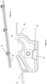
- Figure 1 shows a section of a flight of stairs 1.
- the stair 1 comprises steps, each having a tread surface 2 and a riser surface 3.
- Each step has a leading edge or nosing 4.
- the leading edge or nosing 4 may be formed by placing a nosing extrusion 5 into a stair mould and moulding it into a step of the stair 1.
- the cross-sectional shape of the nosing extrusion 5 is generally designed to ensure that when moulded into a stair it is held firm and cannot be easily dislodged. This may be achieved by providing the nosing extrusion 5 with a coupling interface 6, which creates a profile for securing the nosing extrusion 5 to the stair.
- the coupling interface 6 includes a recess 7 formed in the riser surface 3.
- the material making up the stair preferably concrete, flows into this recess 7.
- the recess 7 has enough volume to ensure that the step beneath the component is sufficiently strong.
- the nosing extrusion 5 preferably has a rear recess 8 causing the formation of a protrusion 9 at the back of the nosing extrusion 5.
- the protrusion 9 will have enough distance from the nosing extrusion's edge on the tread surface 2 to stop any upward movement during the casting of the nosing extrusion 5 in a stair.
- a clamping or recess or groove 10 may also be provided. This receives a positioning device (shown in Figure 4 ) during moulding of a stair, and is used for placement and holding of the nosing extrusion 5 during the stair moulding process.
- a nosing extrusion 5 moulded into a stair 1 is shown in Figure 3 .
- the nosing extrusion 5 is preferably moulded in place at each step edge during the moulding of a stair or staircase, in the manner generally illustrated in Figure 4 .
- a plurality of clamping rods 11 are used to hold each of the nosing extrusions 5 in a correct place in the stair mould 12, or alternatively a short length of a threaded rod (becoming the clamping rods) 13 is fixed on to reinforcing members 14 and then screw downward pressure on to the nosing extrusion 5.
- the stair or staircase may then by formed, as described in US 8 262 055 .
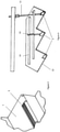
- the nosing assembly 5 of the present invention comprises a plurality of inserts 15 as shown in Figure 5 .
- Each insert 15 comprises a main body portion with a tread surface provided with a plurality of grooves 16 (or some other suitable feature to provide a gripping or non-slip surface).
- the insert 15 may be of any convenient length, for example, 335 mm, 300mm, 280 mm, 125mm or even 75 mm.
- Each insert 15 is provided with an opening 17 extending therethrough.
- Each opening 17 is adapted to accept a tensioning wire or rod, as described in more detail below.
- the opening 17 may be formed by providing a PVC pipe or other suitable tubing, moulded into the insert 15, as also described in more detail below.
- Each insert 15 is provided with a recess 18 of a suitable shape to assist the insert 15 to be retained in a stair.
- the insert 15 is also provided with protrusion 19 and recess 20 for this purpose, along with additional recess 21. This recess 21 assists in clamping the insert 15 into the stair forming mould, in a manner similar to that shown in Figure 4 .
- each end of the insert 15 may also be provided with locating recesses 22, each adapted to house at least a portion of a locating spacer, as described below.
- each locating recess 22 may be tapered slightly, to assist with adequate location of the locating spacers.
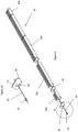
- a nosing assembly 23 of the present invention is shown in Figure 9 .
- the nosing assembly 23 comprises a plurality of inserts 15a and 15b.
- the longer insert sections 15a are usually central sections, located between shorter peripheral insert sections 15b.
- each insert 15a, 15b are adapted to accept a tensioning wire or rod 24 (hereafter wire 24).
- wire 24 may be a 316 stainless steel cable of about 2.5 mm thickness. The use of 316 stainless steel cable will eliminate corrosion.
- At least one end of the wire 24 is provided with a securing means, such as at least one crimping ferrule 25.
- the crimping ferrule 25 may preferably be formed of stainless steel.
- the nosing assembly 23 may be provided with one or more locating spacers 26.
- a locating spacer 26 is provided between each pair of adjacent inserts 15a, 15b and also at each end of the nosing assembly 23.
- the locating spacer 26 is shown in more detail in Figure 10 .
- the locating spacer 26 may comprise a main body 27 with a protrusion 28 extending from one side thereof. A hole extends through the main body 27, to accommodate the wire 24.
- the profile of the locating spacer 26 is preferably substantially similar to the profile of the inserts 15.
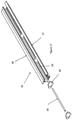
- a plurality of inserts 15 may be selected, and joined together by way of the locating spacers 26 and wire 24, to produce a stair nosing component or nosing extrusion 23 as shown in Figure 11 .
- the inserts 15 may be of any desired length, a suitable number may be selected, in order to form a stair nosing component or nosing extrusion 23 of the desired length.
- the inserts 15 may be made of any desired length, allowing formation of a stair nosing component or nosing extrusion 23 of any desired length.
- individual inserts 15 are shorter than the length of a stair nosing component or nosing extrusion 23, making transport easier and reducing damage that might occur during transportation and use of longer lengths of nosing.
- a second crimping ferrule 25b is located on to the wire 24.
- a tensioning jig 29 is then placed on the wire 24 and is used to tension up the wire 24. This may be done by drawing an end of the wire 24 through a hole in a bolt 30 of the tensioning jig 29, and screwing the bolt 30 inwardly towards the end of the insert 15, as shown in Figure 13 .
- a third crimping ferrule 25c is then located on the wire 24.
- the wire 24 may be pulled tight by hand and then the third, outer crimping ferrule 25c is crimped on to the wire 24.
- the bolt 30 may then be wound outwardly away from the end of the outer insert 15, to tension the wire 24 and thereby draw the inserts 15 firmly together.
- the second, inner crimping ferrule 25b may be positioned up against the end of the outer insert 15 and may be crimped on to the wire 24.
- the wire 24 may then be cut and the tensioning jig 29 removed, resulting in the assembled nosing 23.
- FIG. 14 and 15 An alternative tensioning system is shown in Figures 14 and 15 .
- the inserts 15a, 15b are additionally provided with locating holes 31 and locating pins 32, which engage upon tensioning of the inserts 15a, 15b.
- This arrangement may in some circumstances provide more stability to the nosing assembly 23, for example by preventing twisting of the inserts 15a, 15b relative to one another.
- inserts 15a, 15b and/or the locating spacers 26 may be provided with bevelled edges, as indicated at 33. These bevelled edges help to minimise chipping of the inserts 15a, 15b, which may occur for inserts formed of material such as concrete.
- the insert 15a, 15b may also be provided with a recess 34 at each end. This helps to ensure there are no gaps between adjacent insert sections 15a, 15b and locating spacers 26, to provide a smooth finish to the insert 15.
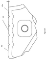
- Each end locating spacer 26a as shown in Figure 16 may preferably be provided with a flat outer surface 35 and the end locating spacers 24a preferably have no grooves on the top surface. These features help to minimise concrete ingress when the insert 15 is placing in the stair mould 12.
- the locating spacers 26 used in between adjacent inserts 15a, 15b may be provided with grooves 16, which in use align with the grooves 16 in the inserts 15a, 15b.
- an insert 15a, 15b of the present invention may be formed using a suitable mould assembly 36.
- the mould assembly 36 comprises two parts, a lower mould extrusion 37 and an upper mould extrusion 38.
- these extrusions may be formed of PVC.
- the mould assembly 36 may be of any desired length, for example from about 2.5 m to 6 m.
- spacer locating former 40 is shown in more detail in Figure 19 .
- the spacer locating former 40 is similar in shape and dimension to the locating spacer 26, but is provided with protrusions 41 for housing ends of the pipes 39.
- the mould assembly 36 is assembled as shown in Figure 17 , concrete is poured into the mould and left to harden or set.
- the mould assembly 36 may be provided with a clamping means (not shown) to clamp the lower mould extrusion 37 and the upper mould extrusion 38 together, while concrete is setting or hardening.
- the inserts 15a, 15b may be removed from the mould assembly 36.
- the upper mould extrusion 38 is removed from the mould assembly 36, leaving the inserts 15a, 15b located in the lower mould extrusion 37.
- the inserts 15a, 15b can then be easily removed from the lower mould extrusion 37, for example by tipping this portion of the mould assembly upside down or by simply lifting each insert 15a, 15b from the lower mould extrusion 37.
- the spacer locating formers 40 may be removed, leaving inserts 15 such as that shown in Figure 5 . It will be appreciated that a piece of pipe 39 is cast permanently into the insert 15a, 15b.
- the top of the spacer locating former 40 and the locating spacer 26 are not flat, as shown in Figure 20 .
- the top is preferably slightly concave, as indicated at 42. This ensures the locating spacers lie flat on the concrete stair mould (they only touch on the outside edges) and there is no concrete ingress on to the top of finished embedded nosing.
- the inserts 15 are also slightly concave. Being slightly concave adds friction and improving anti-slip properties to the stair edging component or nosing extrusion 23.
- inserts 15 may be provided with an additional component 43, as shown in Figure 21 .
- This additional component may be, for example, an LED light or other high visibility component, or an anti-slip component.
- the mould assembly 36 may be provided with an additional pipe or extrusion 44, as shown in Figure 22.
- the pipe or extrusion 44 may be made from PVC so that it may flex inwards for easy removal from the concrete once the insert 15 is made, or it could be left in the insert 15 to enable components to be clipped in.
- the insert 15 of the present invention is made from concrete .
- the insert 15 is made from a strong or hard concrete or concrete composite (optionally, harder and stronger than the concrete forming the stair) so that wear on the edge of each step of a stair is reduced.
- the insert and nosing assembly of the present invention provide a number of useful features. Variable length inserts allow a user to form a nosing assembly of a desired length for any particular stairs, so there is no need to make each nosing to suit a particular customer's requirements. Shorter inserts are also easy to transport to end use locations.
- the nosing assembly of the present invention may be more likely to sit flat in the stair mould because the assembled nosing, with the tensioning wire, allows the assembly to bend and flex even though it is exposed to considerable pressure (for example, over 100kg). Also, some stair moulds may not have flat surfaces and if the nosings are not lying flat on the mould surfaces there will be concrete ingress and the definition between the nosing and the stair faces will be uneven and unsightly. The nosing assembly of the present invention does not need additional reinforcing, which can provide a cost advantage in some situations.
- the spacer/locating system of the present invention provides for accurate formation of the nosing assemblies and stairs comprising such nosing assemblies.
- the manufacture system using sacrificial PVC pipes is accurate and flexible regarding the length of the insert and nosing assembly created.
- the slightly concave shape of the top of the locating spacer and insert ensures the nosing assembly lies flat on the concrete stair mould (the nosing assembly only touches the stair mould on its outside edges as indicated at 42a in Figure 20 ), which prevents any concrete ingress on to the top of finished embedded nosing.
- the degree of concavity is about 3 mm.
Landscapes
- Engineering & Computer Science (AREA)
- Architecture (AREA)
- Mechanical Engineering (AREA)
- Manufacturing & Machinery (AREA)
- Chemical & Material Sciences (AREA)
- Ceramic Engineering (AREA)
- Civil Engineering (AREA)
- Structural Engineering (AREA)
- Steps, Ramps, And Handrails (AREA)
Claims (13)
- Langgestreckter Einsatz (15) für eine führende Kante (4) einer Treppe (1), wobei der Einsatz aufweist:einen Hauptkörper mit einer Trittfläche (2) und einer Kopplungsschnittstelle (6), um den Einsatz mit der Treppe zu koppeln, wobei die Kopplungsschnittstelle wenigstens einen Verhakungsteil zum Befestigen des Einsatzes an der Treppe aufweist,eine Öffnung (17), die sich durch die Länge des Hauptkörpers erstreckt, dadurch gekennzeichnet, dass der Einsatz im Wesentlichen aus Beton ausgebildet ist.
- Einsatz nach Anspruch 1, der ferner aufweist: (i) eine Passaussparung (22) an wenigstens einem seiner Enden oder (ii) eine Passaussparung (22) an jedem seiner Enden.
- Einsatz nach Anspruch 1 oder Anspruch 2, wobei: (i) die Kopplungsschnittstelle (6): wenigstens eine Aussparung (7, 8) für den Eingriff mit einem Rand der Treppe (1) aufweist und/oder (ii) die Kopplungsschnittstelle wenigstens eine Klemmaussparung (10) aufweist, die geeignet ist, während des Formens der Stufe eine Positionierungsvorrichtung (11) aufzunehmen.
- Einsatz nach einem der Ansprüche 1 bis 3, wobei ein Rohr die Öffnung (17) definiert.
- Einsatz nach einem der Ansprüche 1 bis 4, wobei die Trittfläche (2) des Einsatzes wenigstens leicht konkav ist.
- Treppenstufenkomponente (5, 23), die aufweist:mehrere langgestreckte Einsätze (15) nach einem der Ansprüche 1 bis 5,einen Passabstandshalter (26), der zwischen jedem Paar von Einsätzen angeordnet ist, undeine Spanneinrichtung (24), die sich durch die Öffnung (7) in jedem Einsatz und entlang der Länge der Treppenstufenkomponente erstreckt.
- Treppenstufenkomponente nach Anspruch 6, wobei jeder Passabstandshalter (26) mit einer Öffnung, die der Öffnung (17) in jedem Einsatz (15) entspricht, darin versehen ist.
- Treppenstufenkomponente nach Anspruch 6 oder Anspruch 7, wobei das Profil jedes Einsatzes (15) im Wesentlichen ähnlich dem Profil jedes Passabstandshalters (26) ist.
- Treppenstufenkomponente nach einem der Ansprüche 6 bis 8, wobei: (i) wenigstens eine Oberfläche jedes Passabstandshalters (26) wenigstens leicht konkav ist und/oder (ii) die Trittfläche (2) jedes Einsatzes (15) wenigstens leicht konkav ist.
- Treppenstufenkomponente nach einem der Ansprüche 6 bis 9, wobei: (i) die Spanneinrichtung (24) ein Draht oder Seil ist und/oder (ii) die Spanneinrichtung (24) mittels einer oder mehreren Presshülsen (25) befestigt ist.
- Treppenstufenkomponente nach einem der Ansprüche 6 bis 10, wobei die Treppenstufenkomponente ferner einen Passabstandshalter (26) an jedem ihrer Enden aufweist.
- Treppenstufenkomponente nach einem der Ansprüche 6 bis 11, wobei jeder Einsatz (15) ferner mit einem oder mehreren Passstiften (32) versehen ist.
- Verfahren zum Ausbilden einer Treppenstufenkomponente, wobei das Verfahren aufweist:Bereitstellen mehrerer Einsätze (15) nach einem der Ansprüche 1 bis 5,Anordnen eines Passabstandshalters (26) zwischen jedem Paar von Einsätzen, wobei jeder Passabstandshalter mit einer Öffnung versehen ist,Ausfahren einer Spanneinrichtung (24) durch die Öffnung (17) in jedem Einsatz und in jedem Passabstandshalter,Spannen der Spanneinrichtung, bis die mehreren Einsätze und die Passabstandshalter fest zusammengehalten werden.
Applications Claiming Priority (2)
| Application Number | Priority Date | Filing Date | Title |
|---|---|---|---|
| NZ61315913 | 2013-07-12 | ||
| PCT/NZ2014/000142 WO2015005805A1 (en) | 2013-07-12 | 2014-07-11 | Stair edging component |
Publications (3)
| Publication Number | Publication Date |
|---|---|
| EP3019314A1 EP3019314A1 (de) | 2016-05-18 |
| EP3019314A4 EP3019314A4 (de) | 2017-11-08 |
| EP3019314B1 true EP3019314B1 (de) | 2022-02-23 |
Family
ID=52280345
Family Applications (1)
| Application Number | Title | Priority Date | Filing Date |
|---|---|---|---|
| EP14823071.7A Not-in-force EP3019314B1 (de) | 2013-07-12 | 2014-07-11 | Treppenstufenelement |
Country Status (4)
| Country | Link |
|---|---|
| US (1) | US10443246B2 (de) |
| EP (1) | EP3019314B1 (de) |
| AU (1) | AU2014287863B2 (de) |
| WO (1) | WO2015005805A1 (de) |
Families Citing this family (2)
| Publication number | Priority date | Publication date | Assignee | Title |
|---|---|---|---|---|
| EP3019314B1 (de) * | 2013-07-12 | 2022-02-23 | Patent Agencies Limited | Treppenstufenelement |
| US20230313536A1 (en) * | 2022-03-29 | 2023-10-05 | Gary Purewal | Stair nosing |
Family Cites Families (59)
| Publication number | Priority date | Publication date | Assignee | Title |
|---|---|---|---|---|
| US597966A (en) * | 1898-01-25 | Adjustable tread-support for stairs | ||
| US848075A (en) * | 1906-02-07 | 1907-03-26 | Henry H Wainwright | Metal nosing for concrete steps and other structures. |
| US851531A (en) * | 1906-06-19 | 1907-04-23 | Joseph Lea | Stair. |
| US875113A (en) * | 1907-08-09 | 1907-12-31 | Edward Edmund Schachner | Fireproof stair structure. |
| US1377960A (en) * | 1918-04-29 | 1921-05-10 | Norton Co | Antislipping tile |
| US1344310A (en) * | 1919-09-23 | 1920-06-22 | Norman C Parker | Protective pad for stairs |
| US1716224A (en) * | 1926-08-16 | 1929-06-04 | Peter C C Friderichsen | Tile |
| US1681073A (en) * | 1928-02-03 | 1928-08-14 | American Mason Safety Tread Co | Stair nosing |
| US1799405A (en) * | 1930-02-04 | 1931-04-07 | Bois Nathaniel | Stair form |
| US1936224A (en) * | 1931-04-04 | 1933-11-21 | Floor Accessories Company Inc | Edging |
| US2113462A (en) * | 1936-06-04 | 1938-04-05 | Wees Russell J De | Safety tread and method of forming the same |
| US2537396A (en) * | 1949-05-02 | 1951-01-09 | Cato Ernest Earl | Form for casting concrete steps |
| US2835937A (en) * | 1954-04-05 | 1958-05-27 | Colotrym Company | Abrasive stair tread edge molding |
| FR1220512A (fr) | 1958-08-21 | 1960-05-25 | Marche en terre cuite armée, à utiliser pour la mise en oeuvre en encorbellement | |
| US3334456A (en) * | 1963-08-16 | 1967-08-08 | Naka Hiromitsu | Anti-slip stair tread with flexible inserts |
| US3287867A (en) * | 1964-01-03 | 1966-11-29 | Loyd P Aton | Stair nosing |
| US3421274A (en) * | 1966-12-23 | 1969-01-14 | Central Specialties Co | Stair nosing structure |
| US3381775A (en) * | 1967-01-03 | 1968-05-07 | Livers Bronze Company | Stair tread structure |
| US4058942A (en) * | 1973-07-06 | 1977-11-22 | Hiromitsu Naka | Flexible non-skid strip with fluorescent surface portions |
| US4060947A (en) * | 1973-07-06 | 1977-12-06 | Hiromitsu Naka | Flexible non-skid strip with reinforcing web member |
| US4001991A (en) * | 1976-01-02 | 1977-01-11 | Balco, Inc. | Stair nosing structure |
| DE2965870D1 (en) * | 1978-11-13 | 1983-08-18 | Naka Tech Lab | Stair mat |
| EP0011469B1 (de) * | 1978-11-13 | 1984-09-26 | Kabushiki Kaisha Naka Gijutsu Kenkyusho | Teppichmatte für Treppen |
| US4318951A (en) * | 1978-12-28 | 1982-03-09 | Hiromitsu Naka | Stair mat |
| US4455797A (en) * | 1981-09-14 | 1984-06-26 | Kabushiki Kaisha Naka Gijutsu Kenkyusho | Stair nosing |
| DE8404056U1 (de) * | 1984-02-10 | 1984-08-23 | Winter, Rolf, 8000 München | Beleuchtbares stufenkantenprofil |
| DE3542952C1 (de) | 1985-12-05 | 1987-06-19 | Erwin Stern | Verfahren zum Erneuern der Sichtflaechen einer abgetretenen Treppenstufe aus Holz sowie Metallschiene zur Durchfuehrung des Verfahrens |
| DE3701415A1 (de) * | 1987-01-20 | 1988-07-28 | Werner Schlueter | Leiste mit z-foermigem querschnitt zum abschliessen von keramischen platten auf einer stufe oder dergleichen |
| US5051289A (en) * | 1988-10-28 | 1991-09-24 | Milliken Research Corporation | Preformed stair riser title product |
| US5026018A (en) * | 1990-02-26 | 1991-06-25 | Ayala Harry J | Apparatus for forming risers for concrete steps |
| US5253932A (en) * | 1991-12-05 | 1993-10-19 | Nesovic Danilo N | Modular countertop system |
| US5918962A (en) * | 1993-06-16 | 1999-07-06 | Tivoli Industries, Inc. | Dual step light and aisle indicator apparatus |
| US5806253A (en) * | 1996-10-31 | 1998-09-15 | Premark Rwp Holdings, Inc. | Stair nosing for laminate flooring |
| US6076936A (en) * | 1996-11-25 | 2000-06-20 | George; Ben | Tread area and step edge lighting system |
| US5706623A (en) * | 1997-01-02 | 1998-01-13 | Mono Track Systems, Inc. | Carpet edge strip |
| US6115975A (en) * | 1998-04-20 | 2000-09-12 | Abdollahi; Hassan | Stair system |
| US6029408A (en) * | 1998-12-29 | 2000-02-29 | Cavaness Investment Corporation | Pre-fabricated step and stairway system |
| US6258190B1 (en) * | 1999-06-03 | 2001-07-10 | Pete A. Sciarrino | Natural stone tile edging |
| ES2153792B1 (es) * | 1999-08-02 | 2001-10-01 | Friedemann Hoffmann | Dispositivo de señalizacion luminosa para peldaños y gradas. |
| US7080426B2 (en) * | 2004-05-13 | 2006-07-25 | Brass Elegans, Inc. | Carpet stair rod set |
| AT500821B1 (de) * | 2004-10-06 | 2008-01-15 | Neuhofer Franz Jun | Treppe |
| US20060179791A1 (en) * | 2005-02-11 | 2006-08-17 | Steve Shaw | Modular stone surfacing system of block-cut seamless pieces |
| CA2515124A1 (en) * | 2005-08-04 | 2007-02-04 | 3978941 Manitoba Ltd. | Preassembled stair tread member |
| WO2007147238A2 (en) * | 2006-06-20 | 2007-12-27 | Dollar Tile Distributors Ltd. | Laminate stair tread and method therefor |
| USD574106S1 (en) * | 2006-09-06 | 2008-07-29 | Hartman Michael S | Asymmetric light fixture |
| US8262055B2 (en) | 2006-09-12 | 2012-09-11 | Any Step Technology Limited | Stair forming apparatus and related methods |
| US8033063B2 (en) * | 2007-03-07 | 2011-10-11 | Yong Hwan Won | Stair system |
| US8534009B2 (en) * | 2007-12-07 | 2013-09-17 | Ronald J. Kay | Safety nosing components and manufacturing methods |
| US7735238B2 (en) * | 2008-07-31 | 2010-06-15 | General Electric Company | Nozzle trailing edge position measurement and marking |
| US8316594B2 (en) * | 2009-10-07 | 2012-11-27 | Moulure Alexandria Moulding Inc. | Stair tread assembly and method |
| US8505250B2 (en) * | 2010-05-18 | 2013-08-13 | Flooring Industries Limited, Sarl | Finishing for a staircase or step, and kit for forming such finishing |
| US8419205B1 (en) * | 2010-06-01 | 2013-04-16 | Hunter Industries Incorporated | Step light fixture |
| US8850757B2 (en) | 2011-02-10 | 2014-10-07 | William Gardner | Stair nosing assembly |
| US20140013681A1 (en) * | 2012-07-12 | 2014-01-16 | Handi Products, Inc. | Non-Skid Stair Nosing |
| CA2910195C (en) * | 2013-04-26 | 2020-01-21 | Brobbey MENSAH | Method and apparatus for enhancing traction on stair treads |
| EP3019314B1 (de) * | 2013-07-12 | 2022-02-23 | Patent Agencies Limited | Treppenstufenelement |
| CA2893989A1 (en) * | 2014-06-17 | 2015-12-17 | Airwood Vents Inc. | A wood floor nosing and method of making same |
| US9719262B2 (en) * | 2015-06-29 | 2017-08-01 | Cory Halischuk | Kit of parts for trimming step edges |
| US20170328069A1 (en) * | 2016-05-11 | 2017-11-16 | CKJLLC dba Stairtek | Stair tread overlay |
-
2014
- 2014-07-11 EP EP14823071.7A patent/EP3019314B1/de not_active Not-in-force
- 2014-07-11 WO PCT/NZ2014/000142 patent/WO2015005805A1/en not_active Ceased
- 2014-07-11 US US14/904,476 patent/US10443246B2/en not_active Expired - Fee Related
- 2014-07-11 AU AU2014287863A patent/AU2014287863B2/en not_active Ceased
Also Published As
| Publication number | Publication date |
|---|---|
| US20160215502A1 (en) | 2016-07-28 |
| EP3019314A1 (de) | 2016-05-18 |
| US10443246B2 (en) | 2019-10-15 |
| AU2014287863B2 (en) | 2018-03-22 |
| EP3019314A4 (de) | 2017-11-08 |
| AU2014287863A1 (en) | 2016-02-04 |
| WO2015005805A1 (en) | 2015-01-15 |
Similar Documents
| Publication | Publication Date | Title |
|---|---|---|
| US20220234271A1 (en) | Concrete dowel placement system and method of making the same | |
| KR101365513B1 (ko) | 바퀴 고임목 및 제작 방법 | |
| US9169651B1 (en) | Stairway system having an improved baluster assembly | |
| US20140360112A1 (en) | Stair nosing assembly | |
| US10443246B2 (en) | Stair edging component | |
| US11053676B2 (en) | Structure-lining apparatus with adjustable width and tool for same | |
| KR101522022B1 (ko) | 난간용 앵커볼트가 구성된 챌판용 거푸집 및 이를 이용한 계단시공방법 | |
| CA2756368A1 (en) | Composite step tread | |
| US8291662B2 (en) | Continuous pour concrete slip dowel | |
| JP5234361B2 (ja) | 床材連結金具 | |
| KR200486198Y1 (ko) | 전선 배선용 호스 지지구 | |
| KR20190101313A (ko) | 자력식 매입형 앵커 및 이 앵커를 이용한 시설물 시공방법 | |
| KR101866750B1 (ko) | 건물외장재 고정브라켓 제조방법 및 이에 의해 제조되는 건물외장재 고정브라켓 | |
| US20110271481A1 (en) | Baluster Insert | |
| US9765540B2 (en) | Hole repair | |
| KR20170002833U (ko) | 조립식 계단용 기본 블록 | |
| US7305774B1 (en) | Deck board positioning tool | |
| KR101848002B1 (ko) | 계단 챌판용 거푸집을 이용한 주철근 이음구조 | |
| JP2001295441A (ja) | コンクリート階段の施工に使用する蹴込板固定具、蹴込板装置、コンクリート階段の施工構造及びコンクリート階段の施工方法 | |
| CN217711456U (zh) | 一种可拆装式铁艺楼梯 | |
| US20240159059A1 (en) | Staircase capping system and a method of installation | |
| KR200432841Y1 (ko) | 중공 몰딩의 고정 구조체 | |
| EP1557506A2 (de) | Treppenstufe | |
| KR200451208Y1 (ko) | 맨홀용 조립식 사다리의 매립 고정대 | |
| JP2007039978A (ja) | 階段用踏板及び階段用踏板を備えた階段、並びに階段用踏板の製造方法 |
Legal Events
| Date | Code | Title | Description |
|---|---|---|---|
| PUAI | Public reference made under article 153(3) epc to a published international application that has entered the european phase |
Free format text: ORIGINAL CODE: 0009012 |
|
| 17P | Request for examination filed |
Effective date: 20160211 |
|
| AK | Designated contracting states |
Kind code of ref document: A1 Designated state(s): AL AT BE BG CH CY CZ DE DK EE ES FI FR GB GR HR HU IE IS IT LI LT LU LV MC MK MT NL NO PL PT RO RS SE SI SK SM TR |
|
| AX | Request for extension of the european patent |
Extension state: BA ME |
|
| DAX | Request for extension of the european patent (deleted) | ||
| RIC1 | Information provided on ipc code assigned before grant |
Ipc: B28B 7/22 20060101ALI20170601BHEP Ipc: E04G 21/18 20060101ALI20170601BHEP Ipc: B28B 1/14 20060101AFI20170601BHEP Ipc: B28B 23/00 20060101ALI20170601BHEP Ipc: B28B 7/18 20060101ALI20170601BHEP Ipc: E04F 11/16 20060101ALI20170601BHEP |
|
| REG | Reference to a national code |
Ref country code: DE Ref legal event code: R079 Ref document number: 602014082603 Country of ref document: DE Free format text: PREVIOUS MAIN CLASS: B28B0007220000 Ipc: B28B0001140000 |
|
| RIC1 | Information provided on ipc code assigned before grant |
Ipc: B28B 7/18 20060101ALI20170926BHEP Ipc: B28B 7/22 20060101ALI20170926BHEP Ipc: B28B 1/14 20060101AFI20170926BHEP Ipc: E04G 21/18 20060101ALI20170926BHEP Ipc: E04F 11/16 20060101ALI20170926BHEP Ipc: B28B 23/00 20060101ALI20170926BHEP |
|
| A4 | Supplementary search report drawn up and despatched |
Effective date: 20171010 |
|
| RAP1 | Party data changed (applicant data changed or rights of an application transferred) |
Owner name: PAP LIMITED |
|
| RAP1 | Party data changed (applicant data changed or rights of an application transferred) |
Owner name: PATENT AGENCIES LIMITED |
|
| STAA | Information on the status of an ep patent application or granted ep patent |
Free format text: STATUS: EXAMINATION IS IN PROGRESS |
|
| 17Q | First examination report despatched |
Effective date: 20200909 |
|
| GRAP | Despatch of communication of intention to grant a patent |
Free format text: ORIGINAL CODE: EPIDOSNIGR1 |
|
| STAA | Information on the status of an ep patent application or granted ep patent |
Free format text: STATUS: GRANT OF PATENT IS INTENDED |
|
| INTG | Intention to grant announced |
Effective date: 20211102 |
|
| GRAS | Grant fee paid |
Free format text: ORIGINAL CODE: EPIDOSNIGR3 |
|
| GRAA | (expected) grant |
Free format text: ORIGINAL CODE: 0009210 |
|
| STAA | Information on the status of an ep patent application or granted ep patent |
Free format text: STATUS: THE PATENT HAS BEEN GRANTED |
|
| AK | Designated contracting states |
Kind code of ref document: B1 Designated state(s): AL AT BE BG CH CY CZ DE DK EE ES FI FR GB GR HR HU IE IS IT LI LT LU LV MC MK MT NL NO PL PT RO RS SE SI SK SM TR |
|
| REG | Reference to a national code |
Ref country code: GB Ref legal event code: FG4D |
|
| REG | Reference to a national code |
Ref country code: CH Ref legal event code: EP |
|
| REG | Reference to a national code |
Ref country code: AT Ref legal event code: REF Ref document number: 1470093 Country of ref document: AT Kind code of ref document: T Effective date: 20220315 |
|
| REG | Reference to a national code |
Ref country code: IE Ref legal event code: FG4D |
|
| REG | Reference to a national code |
Ref country code: DE Ref legal event code: R096 Ref document number: 602014082603 Country of ref document: DE |
|
| REG | Reference to a national code |
Ref country code: LT Ref legal event code: MG9D |
|
| REG | Reference to a national code |
Ref country code: NL Ref legal event code: MP Effective date: 20220223 |
|
| REG | Reference to a national code |
Ref country code: AT Ref legal event code: MK05 Ref document number: 1470093 Country of ref document: AT Kind code of ref document: T Effective date: 20220223 |
|
| PG25 | Lapsed in a contracting state [announced via postgrant information from national office to epo] |
Ref country code: SE Free format text: LAPSE BECAUSE OF FAILURE TO SUBMIT A TRANSLATION OF THE DESCRIPTION OR TO PAY THE FEE WITHIN THE PRESCRIBED TIME-LIMIT Effective date: 20220223 Ref country code: RS Free format text: LAPSE BECAUSE OF FAILURE TO SUBMIT A TRANSLATION OF THE DESCRIPTION OR TO PAY THE FEE WITHIN THE PRESCRIBED TIME-LIMIT Effective date: 20220223 Ref country code: PT Free format text: LAPSE BECAUSE OF FAILURE TO SUBMIT A TRANSLATION OF THE DESCRIPTION OR TO PAY THE FEE WITHIN THE PRESCRIBED TIME-LIMIT Effective date: 20220623 Ref country code: NO Free format text: LAPSE BECAUSE OF FAILURE TO SUBMIT A TRANSLATION OF THE DESCRIPTION OR TO PAY THE FEE WITHIN THE PRESCRIBED TIME-LIMIT Effective date: 20220523 Ref country code: NL Free format text: LAPSE BECAUSE OF FAILURE TO SUBMIT A TRANSLATION OF THE DESCRIPTION OR TO PAY THE FEE WITHIN THE PRESCRIBED TIME-LIMIT Effective date: 20220223 Ref country code: LT Free format text: LAPSE BECAUSE OF FAILURE TO SUBMIT A TRANSLATION OF THE DESCRIPTION OR TO PAY THE FEE WITHIN THE PRESCRIBED TIME-LIMIT Effective date: 20220223 Ref country code: HR Free format text: LAPSE BECAUSE OF FAILURE TO SUBMIT A TRANSLATION OF THE DESCRIPTION OR TO PAY THE FEE WITHIN THE PRESCRIBED TIME-LIMIT Effective date: 20220223 Ref country code: ES Free format text: LAPSE BECAUSE OF FAILURE TO SUBMIT A TRANSLATION OF THE DESCRIPTION OR TO PAY THE FEE WITHIN THE PRESCRIBED TIME-LIMIT Effective date: 20220223 Ref country code: BG Free format text: LAPSE BECAUSE OF FAILURE TO SUBMIT A TRANSLATION OF THE DESCRIPTION OR TO PAY THE FEE WITHIN THE PRESCRIBED TIME-LIMIT Effective date: 20220523 |
|
| PG25 | Lapsed in a contracting state [announced via postgrant information from national office to epo] |
Ref country code: PL Free format text: LAPSE BECAUSE OF FAILURE TO SUBMIT A TRANSLATION OF THE DESCRIPTION OR TO PAY THE FEE WITHIN THE PRESCRIBED TIME-LIMIT Effective date: 20220223 Ref country code: LV Free format text: LAPSE BECAUSE OF FAILURE TO SUBMIT A TRANSLATION OF THE DESCRIPTION OR TO PAY THE FEE WITHIN THE PRESCRIBED TIME-LIMIT Effective date: 20220223 Ref country code: GR Free format text: LAPSE BECAUSE OF FAILURE TO SUBMIT A TRANSLATION OF THE DESCRIPTION OR TO PAY THE FEE WITHIN THE PRESCRIBED TIME-LIMIT Effective date: 20220524 Ref country code: FI Free format text: LAPSE BECAUSE OF FAILURE TO SUBMIT A TRANSLATION OF THE DESCRIPTION OR TO PAY THE FEE WITHIN THE PRESCRIBED TIME-LIMIT Effective date: 20220223 Ref country code: AT Free format text: LAPSE BECAUSE OF FAILURE TO SUBMIT A TRANSLATION OF THE DESCRIPTION OR TO PAY THE FEE WITHIN THE PRESCRIBED TIME-LIMIT Effective date: 20220223 |
|
| PG25 | Lapsed in a contracting state [announced via postgrant information from national office to epo] |
Ref country code: IS Free format text: LAPSE BECAUSE OF FAILURE TO SUBMIT A TRANSLATION OF THE DESCRIPTION OR TO PAY THE FEE WITHIN THE PRESCRIBED TIME-LIMIT Effective date: 20220623 |
|
| PG25 | Lapsed in a contracting state [announced via postgrant information from national office to epo] |
Ref country code: SM Free format text: LAPSE BECAUSE OF FAILURE TO SUBMIT A TRANSLATION OF THE DESCRIPTION OR TO PAY THE FEE WITHIN THE PRESCRIBED TIME-LIMIT Effective date: 20220223 Ref country code: SK Free format text: LAPSE BECAUSE OF FAILURE TO SUBMIT A TRANSLATION OF THE DESCRIPTION OR TO PAY THE FEE WITHIN THE PRESCRIBED TIME-LIMIT Effective date: 20220223 Ref country code: RO Free format text: LAPSE BECAUSE OF FAILURE TO SUBMIT A TRANSLATION OF THE DESCRIPTION OR TO PAY THE FEE WITHIN THE PRESCRIBED TIME-LIMIT Effective date: 20220223 Ref country code: EE Free format text: LAPSE BECAUSE OF FAILURE TO SUBMIT A TRANSLATION OF THE DESCRIPTION OR TO PAY THE FEE WITHIN THE PRESCRIBED TIME-LIMIT Effective date: 20220223 Ref country code: DK Free format text: LAPSE BECAUSE OF FAILURE TO SUBMIT A TRANSLATION OF THE DESCRIPTION OR TO PAY THE FEE WITHIN THE PRESCRIBED TIME-LIMIT Effective date: 20220223 Ref country code: CZ Free format text: LAPSE BECAUSE OF FAILURE TO SUBMIT A TRANSLATION OF THE DESCRIPTION OR TO PAY THE FEE WITHIN THE PRESCRIBED TIME-LIMIT Effective date: 20220223 |
|
| REG | Reference to a national code |
Ref country code: DE Ref legal event code: R097 Ref document number: 602014082603 Country of ref document: DE |
|
| PG25 | Lapsed in a contracting state [announced via postgrant information from national office to epo] |
Ref country code: AL Free format text: LAPSE BECAUSE OF FAILURE TO SUBMIT A TRANSLATION OF THE DESCRIPTION OR TO PAY THE FEE WITHIN THE PRESCRIBED TIME-LIMIT Effective date: 20220223 |
|
| PLBE | No opposition filed within time limit |
Free format text: ORIGINAL CODE: 0009261 |
|
| STAA | Information on the status of an ep patent application or granted ep patent |
Free format text: STATUS: NO OPPOSITION FILED WITHIN TIME LIMIT |
|
| 26N | No opposition filed |
Effective date: 20221124 |
|
| REG | Reference to a national code |
Ref country code: DE Ref legal event code: R119 Ref document number: 602014082603 Country of ref document: DE |
|
| PG25 | Lapsed in a contracting state [announced via postgrant information from national office to epo] |
Ref country code: SI Free format text: LAPSE BECAUSE OF FAILURE TO SUBMIT A TRANSLATION OF THE DESCRIPTION OR TO PAY THE FEE WITHIN THE PRESCRIBED TIME-LIMIT Effective date: 20220223 Ref country code: MC Free format text: LAPSE BECAUSE OF FAILURE TO SUBMIT A TRANSLATION OF THE DESCRIPTION OR TO PAY THE FEE WITHIN THE PRESCRIBED TIME-LIMIT Effective date: 20220223 |
|
| REG | Reference to a national code |
Ref country code: CH Ref legal event code: PL |
|
| GBPC | Gb: european patent ceased through non-payment of renewal fee |
Effective date: 20220711 |
|
| REG | Reference to a national code |
Ref country code: BE Ref legal event code: MM Effective date: 20220731 |
|
| PG25 | Lapsed in a contracting state [announced via postgrant information from national office to epo] |
Ref country code: LU Free format text: LAPSE BECAUSE OF NON-PAYMENT OF DUE FEES Effective date: 20220711 Ref country code: LI Free format text: LAPSE BECAUSE OF NON-PAYMENT OF DUE FEES Effective date: 20220731 Ref country code: FR Free format text: LAPSE BECAUSE OF NON-PAYMENT OF DUE FEES Effective date: 20220731 Ref country code: CH Free format text: LAPSE BECAUSE OF NON-PAYMENT OF DUE FEES Effective date: 20220731 |
|
| PG25 | Lapsed in a contracting state [announced via postgrant information from national office to epo] |
Ref country code: GB Free format text: LAPSE BECAUSE OF NON-PAYMENT OF DUE FEES Effective date: 20220711 Ref country code: DE Free format text: LAPSE BECAUSE OF NON-PAYMENT OF DUE FEES Effective date: 20230201 Ref country code: BE Free format text: LAPSE BECAUSE OF NON-PAYMENT OF DUE FEES Effective date: 20220731 |
|
| PG25 | Lapsed in a contracting state [announced via postgrant information from national office to epo] |
Ref country code: IT Free format text: LAPSE BECAUSE OF FAILURE TO SUBMIT A TRANSLATION OF THE DESCRIPTION OR TO PAY THE FEE WITHIN THE PRESCRIBED TIME-LIMIT Effective date: 20220223 Ref country code: IE Free format text: LAPSE BECAUSE OF NON-PAYMENT OF DUE FEES Effective date: 20220711 |
|
| PG25 | Lapsed in a contracting state [announced via postgrant information from national office to epo] |
Ref country code: HU Free format text: LAPSE BECAUSE OF FAILURE TO SUBMIT A TRANSLATION OF THE DESCRIPTION OR TO PAY THE FEE WITHIN THE PRESCRIBED TIME-LIMIT; INVALID AB INITIO Effective date: 20140711 |
|
| PG25 | Lapsed in a contracting state [announced via postgrant information from national office to epo] |
Ref country code: MK Free format text: LAPSE BECAUSE OF FAILURE TO SUBMIT A TRANSLATION OF THE DESCRIPTION OR TO PAY THE FEE WITHIN THE PRESCRIBED TIME-LIMIT Effective date: 20220223 Ref country code: CY Free format text: LAPSE BECAUSE OF FAILURE TO SUBMIT A TRANSLATION OF THE DESCRIPTION OR TO PAY THE FEE WITHIN THE PRESCRIBED TIME-LIMIT Effective date: 20220223 |
|
| PG25 | Lapsed in a contracting state [announced via postgrant information from national office to epo] |
Ref country code: MT Free format text: LAPSE BECAUSE OF FAILURE TO SUBMIT A TRANSLATION OF THE DESCRIPTION OR TO PAY THE FEE WITHIN THE PRESCRIBED TIME-LIMIT Effective date: 20220223 |
|
| PG25 | Lapsed in a contracting state [announced via postgrant information from national office to epo] |
Ref country code: TR Free format text: LAPSE BECAUSE OF FAILURE TO SUBMIT A TRANSLATION OF THE DESCRIPTION OR TO PAY THE FEE WITHIN THE PRESCRIBED TIME-LIMIT Effective date: 20220223 |