EP3019323B1 - Transmission et actionneur électrique montés de manière non coaxiale - Google Patents
Transmission et actionneur électrique montés de manière non coaxiale Download PDFInfo
- Publication number
- EP3019323B1 EP3019323B1 EP14742706.6A EP14742706A EP3019323B1 EP 3019323 B1 EP3019323 B1 EP 3019323B1 EP 14742706 A EP14742706 A EP 14742706A EP 3019323 B1 EP3019323 B1 EP 3019323B1
- Authority
- EP
- European Patent Office
- Prior art keywords
- actuator
- pin
- travel
- valve pin
- upstream
- Prior art date
- Legal status (The legal status is an assumption and is not a legal conclusion. Google has not performed a legal analysis and makes no representation as to the accuracy of the status listed.)
- Not-in-force
Links
- 230000005540 biological transmission Effects 0.000 title claims description 36
- 230000008878 coupling Effects 0.000 claims description 57
- 238000010168 coupling process Methods 0.000 claims description 57
- 238000005859 coupling reaction Methods 0.000 claims description 57
- 238000011144 upstream manufacturing Methods 0.000 claims description 51
- 230000033001 locomotion Effects 0.000 claims description 21
- 238000001746 injection moulding Methods 0.000 claims description 19
- 238000002347 injection Methods 0.000 claims description 14
- 239000007924 injection Substances 0.000 claims description 14
- 239000012530 fluid Substances 0.000 claims description 8
- 239000000463 material Substances 0.000 claims description 7
- 238000001514 detection method Methods 0.000 claims description 4
- 230000000295 complement effect Effects 0.000 description 14
- 238000006243 chemical reaction Methods 0.000 description 3
- 230000007246 mechanism Effects 0.000 description 3
- 229910001220 stainless steel Inorganic materials 0.000 description 2
- 239000010935 stainless steel Substances 0.000 description 2
- 230000000712 assembly Effects 0.000 description 1
- 238000000429 assembly Methods 0.000 description 1
- 238000005452 bending Methods 0.000 description 1
- 230000015572 biosynthetic process Effects 0.000 description 1
- 238000001816 cooling Methods 0.000 description 1
- 239000002184 metal Substances 0.000 description 1
- 238000000034 method Methods 0.000 description 1
- 230000008439 repair process Effects 0.000 description 1
- 230000002441 reversible effect Effects 0.000 description 1
- 239000007787 solid Substances 0.000 description 1
- 238000007711 solidification Methods 0.000 description 1
- 230000008023 solidification Effects 0.000 description 1
- 125000006850 spacer group Chemical group 0.000 description 1
- XLYOFNOQVPJJNP-UHFFFAOYSA-N water Substances O XLYOFNOQVPJJNP-UHFFFAOYSA-N 0.000 description 1
Images







Classifications
-
- B—PERFORMING OPERATIONS; TRANSPORTING
- B29—WORKING OF PLASTICS; WORKING OF SUBSTANCES IN A PLASTIC STATE IN GENERAL
- B29C—SHAPING OR JOINING OF PLASTICS; SHAPING OF MATERIAL IN A PLASTIC STATE, NOT OTHERWISE PROVIDED FOR; AFTER-TREATMENT OF THE SHAPED PRODUCTS, e.g. REPAIRING
- B29C45/00—Injection moulding, i.e. forcing the required volume of moulding material through a nozzle into a closed mould; Apparatus therefor
- B29C45/17—Component parts, details or accessories; Auxiliary operations
- B29C45/26—Moulds
- B29C45/27—Sprue channels ; Runner channels or runner nozzles
- B29C45/28—Closure devices therefor
- B29C45/2806—Closure devices therefor consisting of needle valve systems
- B29C45/281—Drive means therefor
-
- B—PERFORMING OPERATIONS; TRANSPORTING
- B29—WORKING OF PLASTICS; WORKING OF SUBSTANCES IN A PLASTIC STATE IN GENERAL
- B29C—SHAPING OR JOINING OF PLASTICS; SHAPING OF MATERIAL IN A PLASTIC STATE, NOT OTHERWISE PROVIDED FOR; AFTER-TREATMENT OF THE SHAPED PRODUCTS, e.g. REPAIRING
- B29C45/00—Injection moulding, i.e. forcing the required volume of moulding material through a nozzle into a closed mould; Apparatus therefor
- B29C45/17—Component parts, details or accessories; Auxiliary operations
- B29C45/26—Moulds
- B29C45/27—Sprue channels ; Runner channels or runner nozzles
- B29C45/28—Closure devices therefor
-
- B—PERFORMING OPERATIONS; TRANSPORTING
- B29—WORKING OF PLASTICS; WORKING OF SUBSTANCES IN A PLASTIC STATE IN GENERAL
- B29C—SHAPING OR JOINING OF PLASTICS; SHAPING OF MATERIAL IN A PLASTIC STATE, NOT OTHERWISE PROVIDED FOR; AFTER-TREATMENT OF THE SHAPED PRODUCTS, e.g. REPAIRING
- B29C45/00—Injection moulding, i.e. forcing the required volume of moulding material through a nozzle into a closed mould; Apparatus therefor
- B29C45/17—Component parts, details or accessories; Auxiliary operations
- B29C45/26—Moulds
- B29C45/27—Sprue channels ; Runner channels or runner nozzles
- B29C45/28—Closure devices therefor
- B29C45/2806—Closure devices therefor consisting of needle valve systems
- B29C45/281—Drive means therefor
- B29C2045/282—Needle valves driven by screw and nut means
-
- B—PERFORMING OPERATIONS; TRANSPORTING
- B29—WORKING OF PLASTICS; WORKING OF SUBSTANCES IN A PLASTIC STATE IN GENERAL
- B29C—SHAPING OR JOINING OF PLASTICS; SHAPING OF MATERIAL IN A PLASTIC STATE, NOT OTHERWISE PROVIDED FOR; AFTER-TREATMENT OF THE SHAPED PRODUCTS, e.g. REPAIRING
- B29C45/00—Injection moulding, i.e. forcing the required volume of moulding material through a nozzle into a closed mould; Apparatus therefor
- B29C45/17—Component parts, details or accessories; Auxiliary operations
- B29C45/26—Moulds
- B29C45/27—Sprue channels ; Runner channels or runner nozzles
- B29C45/28—Closure devices therefor
- B29C45/2806—Closure devices therefor consisting of needle valve systems
- B29C45/281—Drive means therefor
- B29C2045/2824—Needle valves driven by an electric motor
-
- B—PERFORMING OPERATIONS; TRANSPORTING
- B29—WORKING OF PLASTICS; WORKING OF SUBSTANCES IN A PLASTIC STATE IN GENERAL
- B29C—SHAPING OR JOINING OF PLASTICS; SHAPING OF MATERIAL IN A PLASTIC STATE, NOT OTHERWISE PROVIDED FOR; AFTER-TREATMENT OF THE SHAPED PRODUCTS, e.g. REPAIRING
- B29C45/00—Injection moulding, i.e. forcing the required volume of moulding material through a nozzle into a closed mould; Apparatus therefor
- B29C45/17—Component parts, details or accessories; Auxiliary operations
- B29C45/26—Moulds
- B29C45/27—Sprue channels ; Runner channels or runner nozzles
- B29C45/28—Closure devices therefor
- B29C45/2806—Closure devices therefor consisting of needle valve systems
- B29C45/281—Drive means therefor
- B29C2045/2837—Needle valves driven by rack and pinion
-
- B—PERFORMING OPERATIONS; TRANSPORTING
- B29—WORKING OF PLASTICS; WORKING OF SUBSTANCES IN A PLASTIC STATE IN GENERAL
- B29C—SHAPING OR JOINING OF PLASTICS; SHAPING OF MATERIAL IN A PLASTIC STATE, NOT OTHERWISE PROVIDED FOR; AFTER-TREATMENT OF THE SHAPED PRODUCTS, e.g. REPAIRING
- B29C45/00—Injection moulding, i.e. forcing the required volume of moulding material through a nozzle into a closed mould; Apparatus therefor
- B29C45/17—Component parts, details or accessories; Auxiliary operations
- B29C45/26—Moulds
- B29C45/27—Sprue channels ; Runner channels or runner nozzles
- B29C45/28—Closure devices therefor
- B29C45/2806—Closure devices therefor consisting of needle valve systems
- B29C2045/2865—Closure devices therefor consisting of needle valve systems having position detecting means
Definitions
- Injection molding systems using electric actuators have been developed having a drive rotor with an axis aligned with the axis of a valve pin to cause the pin to move either upstream or downstream over the course of the injection portion of an injection cycle in order to raise or lower the rate of flow of fluid material to correspond to a predetermined profile of fluid flow rates for the injection cycle, see for example documents US 8 091 202 B2 and WO 2010/128984 A1 .
- an apparatus for controlling the rate of flow of fluid mold material from an injection molding machine to a mold cavity comprising:
- the pin connector may comprise an adapter coupled to a top or upstream end of the stem, the adapter configured to be reversibly receivable within the coupling in a radial direction.
- the adapter preferably comprises an enlarged head which is reversibly couplable to and decouplable from the coupling.
- the apparatus is preferably adapted to allow the pin connector to travel a selected radial distance within the coupling and to remain coupled while the top clamping or mounting plate remains coupled to the mold and the pin stem remains extended into the manifold.
- the pin stem is typically mounted to the manifold for radial movement of the pin stem together with the manifold relative to the top clamping or mounting plate.
- the apparatus is preferably adapted to allow the adapter to travel a selected radial distance within the coupling relative to the axial path of travel while the mounting plate remains coupled to the mold, the pin connector remains coupled to the actuator coupling and the pin stem remains extended into the manifold.
- the top clamping or mounting plate is typically decouplable from the mold leaving the pin stem extended into the manifold when the adapter is decoupled from the coupling.
- the motor housing is preferably removably attached to the top clamping or mounting plate and the transmission housing is removably attached to the motor housing.
- the transmission housing can be removably attached to the top clamping or mounting plate and the motor housing is removably attached to the motor housing.
- the actuator is typically interconnected to a controller that includes instructions that instruct the actuator to drive the valve pin upstream continuously beginning from the closed position to one or more intermediate upstream positions at one or more intermediate rates of travel that are less than a maximum velocity at which the actuator is capable of driving the valve pin for either a predetermined amount of time or for a predetermined length of upstream travel.
- the actuator can include instructions that instruct the actuator to drive the valve pin continuously upstream from the one or more intermediate upstream positions to a maximum upstream position at one or more high rates of travel that are equal to or greater than the one or more intermediate rates of travel.
- the apparatus further can comprise a position sensor that senses a position of either the actuator or the valve pin, the position sensor sensing the position of the actuator or the valve pin and sending a signal indicative of the position of the actuator or the valve pin to the controller; the controller instructing the actuator to drive the valve pin continuously upstream from the one or more intermediate upstream positions at the one or more high rates of travel on detection by the position sensor of the valve pin at the one or more intermediate upstream positions.
- the drive gear and the transmission gear are typically rotatably interconnected via gears or via belt and pulley.
- the controller can include instructions that instruct the actuator to drive the valve pin at one or more high rates of downstream travel that are equal to or less than a maximum rate of downstream travel at which the actuator is capable of driving the valve pin when the valve pin is disposed at a maximum upstream position during the course of an injection cycle,
- the controller including instructions that instruct the actuator to drive the valve pin at one or more intermediate rates of downstream travel that are less than the one or more high rates of downstream travel on expiration of a predetermined amount of time or for a predetermined amount of downstream travel of the valve pin from the maximum upstream position.
- the apparatus can further comprise a position sensor that senses a position of either the actuator or the valve pin, the position sensor sensing the position of the actuator or the valve pin and sending a signal indicative of the position of the actuator or the valve pin to the controller; the controller instructing the actuator to drive the valve pin continuously downstream at the one or more intermediate rates of downstream travel on detection by the position sensor of the valve pin having travelled the predetermined amount of downstream travel from the maximum upstream position.
- a position sensor that senses a position of either the actuator or the valve pin, the position sensor sensing the position of the actuator or the valve pin and sending a signal indicative of the position of the actuator or the valve pin to the controller; the controller instructing the actuator to drive the valve pin continuously downstream at the one or more intermediate rates of downstream travel on detection by the position sensor of the valve pin having travelled the predetermined amount of downstream travel from the maximum upstream position.
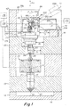
- Figs. 1 , 2 shows one embodiment of the invention comprised of an electric actuator 66 assembly that is comprised of an electric motor 64 drivably interconnected to a gear 72/190 in a non-coaxially aligned X-Y arrangement.
- the shaft 60 of the electrically driven motor 64 has an axis Y, the shaft 60 being rotatably driven by electrical power, the shaft 60 being interconnected to a valve pin 50 through a bevel gear engagement between the head 190 of a screw 72 and the head 191 of an extension member 61 of the motor shaft 60.
- the screw component 72 can alternatively have threads along its length (in place of the beveled head 190) which mesh with a worm at the end of extension 61 (in place of the beveled member 191).
- the axis Y of the shaft 60 is non-coaxially perpendicular to the axis X of the pin 50 and the actuating screw mechanism 72 such that axial forces which may occur along axis X are not transmitted along axis Y to the shaft 60.
- Shaft extension member61 is coaxially connected to the motor shaft 60(via rigid connection between connecting disc 210 and a complementary connecting member attached to shaft60which is not shown) such that as the shaft60is rotatably driven around axis Y the extension member61 and its associated bevel gear191 are simultaneously rotatably driven around axis Y.
- screw 72 is rotatably driven around axis X via the meshed bevel gears 190, 191
- pin 50 is translationally driven along axis X via the screwable engagement between nut end 195 and screw 72.
- the screw 72 acts as an actuating member to and through which axial forces are transmitted to and from pin50.
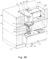
- Figs. 1 , 3A , 3B , 4 , 5 show an embodiment where the electric motor 64 component of the actuator 66 is coupled to the top clamp plate 39 via bolts 79 interconnecting motor housing portion 64a and plate 39.
- Complementary tapped holes are provided in the upper surface of the upper mounting plate 39 for receiving the bolts 79 and securing the motor housing 64 to the plate 39. This prevents rotational and other movement of the housing 64 and gear box housing 58 with respect to the mounting plates 39, 45 and manifold 24 and the injection molding apparatus generally.
- Extending downwardly from the screw 195 is a cylindrical projection 74 from which the downstream neck 75 of the coupler screw extends.
- Figs. 3 , 4 show an alternative mounting of the motor housing 64 to the top clamp plate 39 via an extension 64a and bolt 79, as alternative to the mounting of the transmission gear housing 58 to the top clamping or mounting plate 45 via bolts 77.
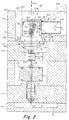
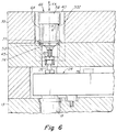
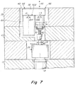
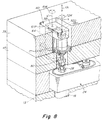
- Figs. 2 , 6 , 7 , 8 , 9 show an alternative embodiment where the gear box 58 includes four bores 76, one in each corner of the housing, for receiving bolts 77 that removably couple the gear box housing 58 to the lower mounting plate 45.
- Four complementary tapped holes 50 are provided in the upper surface 48 of the lower mounting plate 45 for receiving the bolts 77 and securing the gear box housing 58 to the plate 45. This prevents rotational and other movement of the housing 58 and its attached motor 64 with respect to the mounting plates 39, 45 and manifold 24 and the injection molding apparatus generally.
- Extending downwardly from the screw 195 is a cylindrical projection 74 from which the neck 75 of the coupler screw extends.
- Figs. 2-10 all show one alternative arrangement where the gear housing 58 is bolted 77 to the top clamp or mounting plate 45 as an alternative to mounting of the motor housing 64 to the top clamp or mounting plate 39.
- housings 58 and 64 are fixedly connected to each other by conventional attachment mechanism 502 such that when one of the housings 58 or 64 is fixedly bolted 77 or 79 to a clamp or mounting plate 39, 45, the other of the two housings 58 or 64 is fixedly mounted to the same plate via fixed connection between 502 the two housings 58, 64.
- Figs. 1 , 2 show the actuator 66 comprised of a transmission assembly 58a that is comprised of a gear box 58 assembled together with the other components of the system to form a stack that includes a nozzle 18 mounted in a receiving well 15 formed within a mold plate 13 in an injection molding stack arrangement.
- a heated manifold 24 is disposed between the pair of upstream top clamping or mounting plates 39/45 and the downstream mold plates 13/14.
- the valve pin 31 is mounted to the manifold within a bushing 28 having a complementary internal bore for slidably receiving the pin 31 such that the pin can reciprocally travel XX along axis X.
- the valve pin 31 has a downstream distal tip end that opens and closes a gate aperture 20 that leads to the mold cavity 19.
- the mounting plates 39, 45 and mold plates 13, 14 are fixedly secured together under high clamp pressure, so as to withstand high injection molding forces.
- a nozzle 18 extends through a bore 15 in the lower mold plate 14, and seats and unseats in the gate 20 to the injection mold cavity 19.
- the actuator 66 is disposed in a chamber 40 of the upper mounting plate 39, with a radial clearance 3 provided in at least one radial direction so as to facilitate the radial coupling and decoupling of the pin head adapter 94 and actuator coupling 80.
- the electric motor is powered and driven by electrical energy or power input to coils that typically rotatably drive a magnet that in turn rotatably drives motor shaft 61.
- the distal end of the rotor 61 of the motor 64 has a beveled gear head 191 that meshes with and rotatably drives a beveled gear head 190 formed on the shaft of a linear travelling XX screw 72 (linear travel converter) that comprise the transmission assembly 58a.
- the gear head 190 is integrally formed together with a shaft having a downstream end that has male threads forming a screw 72 that is screwably engaged within the female screws bored within the upstream head 195 of a linear conversion screw 197.
- the downstream distal end of the screw 197 is connected to actuator coupling 80 which removably receives the upstream head portion 94 of valve pin 31 as described in detail in U.S. Patent No.
- the driven rotation motion 61R of motor shaft 61 is thus converted from rotatable motion to controllably driven linear motion XX along axis X of the valve pin 31 via the driven rotation of the gear screw 72 and driven linear movement of the linear conversion screw 197 via the screwable engagement of screw and head 195.
- the arrangement or disposition of the motor axis Y is non-coaxial to the axis X of the transmission gear and screws 72, 195, 197 and valve pin 31.
- the arrangement of the axes X and Y can be about 90 degrees relative to each other.
- the axis Y1 of the drive shaft can be disposed at any non-coaxial angle between zero and 180 degrees relative to the axis X of the transmission and valve pin, the design of the meshed gears 190, 191 being adapted to enable such an arrangement.
- Figs. 3A , 3B shows another gearing arrangement where a circular gear 800 attached to distal end of motor drive shaft 61 is controllably rotatably drivable 61R around axis Y to drive XX the gear rack 802 (linear travel converter) along axis X via meshing of the gears of gear 800 with the gears of rack 802, the rack 802 being fixedly attached to the upstream end of a linear traveler rod 197a that is interconnected at its downstream end to coupler 80.
- the valve pin when coupled to coupler 80 is controllably drivable along the X axis by controlled driving of the shaft 61 of the motor around the perpendicular axis Y.
- the motor 64 housing (or the gear box housing 58) could be mounted to the top clamping plate or mounting plate in an arrangement such that the drive shaft 61 of the motor 64 is aligned along the Z axis and a gear attached to the distal end of the shaft is meshed with a complementary gear at the upstream end of a complementary linear travel converter screw or rod similar to those described above regarding the Figs. 1-3B embodiments to drive the valve pin along the non-coaxial axis X.
- driven rotation movement 61R of a motor shaft 61 is similarly converted to linear movement XX via interconnection of the motor shaft 61 to a pulley 61P and interconnection of the transmission shaft to a transmission pulley 58P with the two pulleys 58P, 61P being rotatably interconnected by belt 500.
- the axis Y of the motor rotor 61 is non-coaxial to the axis X of the transmission, the axes X and Y shown as being disposed at 180 degrees to each other.
- Other non-coaxially aligned arrangements of the axes X and Y, other than 180 degrees, can be assembled using appropriate components to interconnect pulleys 58P, 61P.
- Fig. 9 shows an embodiment where the transmission pulley 58P has a central internal thread that screwably receives a complementary threaded screw shaft 58S that is driven axially XX by rotation of the pulley 58P.
- the downstream end of the screw shaft 58S is interconnected to a downstream linear drive stem 195a which is interconnected to or otherwise forms the valve pin 31 of the system.
- the drive stem 195a is driven linearly XX along X by screw shaft 58S.
- the drive stem 195a is adapted to be non-rotatable by formation of a flat surface 195f on the outer circumference of the stem 195a and by mounting a stationarily mounted stop member 195S having a complementary flat surface 195ff that is engaged against the flat surface 195f of the stem 195a to prevent rotation thereof.
- the stem 195a can be a separate part or can be formed as integral with the valve pin itself, in either case the valve pin being non-rotatably by virtue of the flats 195f, 195ff.
- An electronic controller 176 can be interconnected to the electric motor. Such a controller is capable of precisely driving the electric coils according to any pre-programmed electronic program, circuit or microcontroller to in turn precisely drive the valve pin to any selected positions along the axis X such that the position of the tip end of the valve pin relative to the gate is precisely controlled over the course of an injection molding cycle.
- a position sensor 178 can be used to sense the position of any component of the system that relates to the axial X of the valve pin 31.
- a sensor 178 can sense 177 the rotational or axial position of the transmission gear 190, 72, the transmission linear conversion screw 195, the axis of the rotor 61 of the motor 64 such, the internal screw within the motor that drives the rotor or the magnet that drives the rotor 61, or the position sensor can alternatively sense 179 the axial position of the valve pin 31 itself.
- the signal 177, 179 that indicates position is input to the controller 176 which can use such a real-time signal in a program to control the rate of drive of the motor rotor 61 and transmission components 190, 72, 195 which in turn control the velocity or rate of travel of upstream withdrawal or downstream closure of the valve pin 31 at selected times or over selected lengths of time over the course of an injection cycle.
- the actuator assembly 66 is generically depicted as a box 66 for purposes of explanation as to how an assembly 66 as described above can be coupled, decoupled and moved laterally and upstream-downstream within a complementary receiving recess provided within plates 39, 45 such that the pin coupling can be coupled to and decoupled from the pin connector without having to dissemble the plates 39, 45 or the actuator 66.
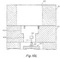
- Figs. 10A-10M depict the actuator 66 as a single parallelepiped shaped box
- the box 66 as shown in Figs. 10A-10M is analogous to the differently shaped assemblies 66 as described with reference to Figs. 1-9 at least regarding how the assembly can be coupled, decoupled and moved within the recess 40 formed within plates 39, 45.
- the nozzle 18 is mounted in or on one or more metal (e.g. stainless steel) plates.
- the apparatus includes a heated manifold 24 and one or more other spacer, mounting or mold plates 13, 14.
- the manifold 24 is heated to maintain the nozzle 18 at an elevated temperature for delivery of the molten plastic.
- the mold cavity 19 and plates 13, 14 are typically maintained relatively cool by water cooling channels compared to the manifold 24 to enable solidification of the injected molten plastic to form a solid plastic article within the cavity of the mold.
- the nozzle 18 is an elongated tubular article 19 typically made of stainless steel and having a central axial bore 21 through which the molten plastic travels to the gate 20 and into the mold cavity. Also in the nozzle bore, aligned along the central bore axis, is an axially elongated valve pin 30 having an axially elongated stem 31, which defines the valve pin axis AA. At one end of the stem, designed to seat and unseat in the nozzle gate for purposes of opening and closing the gate, and effectively starting and stopping flow of the molten plastic to the mold cavity, the stem has an angular or tapered lowermost tip 32.
- a pin head 34 which in the present embodiment comprises a radially enlarged cylindrical member that is receivable within a pin head adapter 94.
- the valve stem 31 also extends through an elongated plastic feed bore 27 in the heated manifold 24, typically also substantially coaxial with the nozzle bore.
- the valve stem 31 is guided into and mounted to the manifold 24 by a bushing 28 which receives, guides and mounts the valve stem 31 in the manifold plastic feed bore 27.
- the pin head 34 and any associated adapter 94 extends axially upstream beyond and from the bushing on the upstream or top side 25 of the manifold.
- the pin head 34 may be formed integral with the valve stem 33 (as a single part) or it may be formed as a separate part and then secured to the upstream or top end of the valve stem by conventional means. It may or may not be radially enlarged but is typically formed in a radially enlarged configuration for ease of ready connectivity to and disconnectivity from an adapter component or pin coupling as described below.
- a pair of upper and lower mounting plates 39, 45 are provided in or on which the actuator 66 is mounted.
- the plates 39 and 45 are sometimes referred to as top clamping plates, clamping plates or backing plates.
- the actuator 66 via the transmission drives the valve pin stem axially A, X (linearly) along the coaxial bores of the manifold and nozzle.
- the housing of the actuator assembly 66 is disposed within a receiving aperture or chamber 40 in the upper mounting plate 39 and/or a chamber 40a in the lower mounting plate 45.
- the assembly 66 can be fixed to the lower mounting plate 45 by threaded bolts 77 which extend into complementary threaded holes 50 in plate 45 so as to removably couple the actuator housing to the mounting plate 39 (see Fig. 10F ).
- the actuator housing can be attached via bolts 79.
- the mounting plates 39, 45 are removably coupled to the mold typically by bolts or similar reversible fastening mechanisms.
- the chamber 40 of the upper mounting plate 39 (in which the actuator 66 is disposed) is actually a through bore in the upper plate 39 extending from the top surface 42 to the bottom surface 43.
- the neck 75 extends downwardly into a co-axial bore 40a/40b in the lower mounting plate 45 (40/40a/40b are coaxial).
- a pin coupling 80 is attached to or mounted on the neck 75 and is also disposed in the bore 40a/40b of the lower mounting plate 39 when the actuator is connected to the mounting plate.
- the coupling 80 includes a radial recess 83, disposed laterally (traverse to the elongated valve pin axis.
- the recess has a radial recess opening 82 that allows a pin head 34 or pin head adapter 94 to be radially inserted into and removed from the radial recess.
- the coupling 80 also includes a radial slot 84, connected (open) to the radial recess and extending downwardly to the lower surface 90 of the coupling 80.
- the radial slot has a radial slot opening 85 through which the valve stem 31 can be readily radially inserted or translated within (or removed from) the slot 84 while the adapter 94 is simultaneously radially inserted or translated within (or removed from) the radial recess 82.
- the coupling 80 has walls 91 that form and act as a housing for the radial recess 83 and radial slot 84.
- the pin connector 94 and the recess 83 and recess opening 84 are configured to have a complementary geometry, size, shape and configuration so as to enable the pin connector to be received within the recess 83 and fully surrounded and contained within walls 91 and also to require that the pin connector 94 is receivable within and removable from the recess 83 only by movement of the pin connector 94 in a radial direction R, Fig. 10B , transverse to the axial path of travel A of the neck 75.
- the pin connector 94 is slidable by manual force along radial direction R into and out of the recess 83 and recess opening 84.
- the pin stem 31 is simultaneously slidable radially through slot opening 85 into slot 84.
- the walls 91 act to retain and couple the pin connector 94 and associated pin stem 31 to the neck 75 when the connector 94 is received within recess 83 and stem 31 in slot 84.
- the radial recess 82 is sized and configured to provide a radial clearance 2 in all radial directions between the valve pin adapter 94 and the recess 82 when/while the adapter is received and coupled within the recess 82 of the coupling 80.
- This radial clearance 2 allows movement in any radial direction of the valve pin adapter while it is mounted in the recess of the actuator coupling, so as to accommodate differences in thermal expansion between various components of the injection molding apparatus such as between the manifold 24 and the mounting plates 39, 45.
- the valve stem 31 is mounted to a manifold 24 when the system is assembled, the manifold being heated during the course of startup to a higher temperature than the relatively cold mounting plates 39, 45 and cold actuator 66.
- valve pin assembly pin 30 and adapter 94
- the valve pin assembly which is mounted to the manifold by the bushing 28 and travels radially therewith and is also being heated via the manifold, to move radially together with the manifold with respect to the mounting plate and the axial path of travel of the actuator so as to prevent the application of undesirable side bending forces on the valve pin assembly.
- These side forces may bend or break the valve stem or otherwise interfere with proper alignment and operation of the valve pin assembly and actuator.
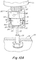
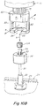
- Figs. 10A , 10B show one embodiment of the coupling apparatus in an assembled state ( Fig. 10A ) and a disassembled state (10B).
- Fig.10A the upper end of the valve pin is shown extending upwardly from a manifold bushing 28 secured to the top 25 of the manifold.
- the pin head 34 and attached adapter 94, at the top end of the valve pin, are disposed completely within the coupling 80 in Fig.10A .
- the adapter 94 is radially received in the radial recess 82 of the coupling 80, while the valve stem 31 resides in the radial slot 84 of the coupling.
- the actuator coupling 80 is connected to the spline shaft or neck 75 that is interconnected to the electric actuator motor, by a pin 88 which extends through a bore 87 in the coupling and into a bore in the shaft. This prevents rotation of the coupling relative to the actuator shaft.
- Fig. 10B shows the disassembled pin coupling 80 and pin head adapter 94.
- a cylindrical set screw 104 having outer threads is adapted for threaded engagement with the pin head adapter 94.
- the pin head adapter 94 has a central axial through bore 99 extending from the top surface 96 to the bottom surface 97 of the adapter. The bore receives the upper end of the valve stem and pin head 34.
- the pin head 34 sits on a shoulder 100 in the central bore and is secured in the adapter 94 by screwing the set screw 104 into a threaded upper portion of the bore, creating a pressure engagement of the pin head and adapter.
- the adapter essentially functions as an enlarged pin head.
- the adapter may not be required, as the pin head itself could be disposed in the radial recess of the actuator coupling.
- Fig. 10E shows the actuator housing including four bores 76, one in each corner of the housing, for receiving bolts 77 that removably couple the motor or gear housing 58, 64 to the lower mounting plate 45.
- Four complementary tapped holes 50 are provided in the upper surface 48 of the lower mounting plate 45 for receiving the bolts 77 and securing the motor housing to the plate. This prevents rotational and other movement of the housing of the motor with respect to the mounting plates and manifold and the injection molding apparatus generally.
- Extending downwardly from the motor or gear housing 58, 64 is a cylindrical projection 74 from which the neck 75 extends. Coupled to the downstream end of the neck 75 is the actuator coupling 80 and extending axially downstream from the coupling 80 is the valve stem 31.
- Fig. 10F is a cross section showing the injection molding stack.
- a heated manifold 24 is disposed between the mounting plates 39/45 and mold plates 13/14.
- the mounting plates and mold plates are fixedly secured together under high clamp pressure, so as to withstand high injection molding forces.
- a nozzle 18 extends through a bore 15 in the lower mold plate 14, and seats and unseats in the gate 20 to the injection mold cavity.
- the actuator 66 housing is disposed in a chamber 40 of the upper mounting plate 39, with a radial clearance 3 provided in at least one radial direction so as to facilitate the radial coupling and decoupling of the pin head adapter and actuator coupling.
- Fig. 10G is a top plan view of the apparatus of Fig. 10F , but with the electric motor removed.
- the chamber 40 has a rectilinear cross section.
- the upper bore 40a has an oval cross section, and the lower bore 40b also has an oval but smaller, cross section, providing a radial clearance along the long axis L of the oval, to facilitate the assembly and disassembly steps described below.
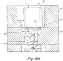
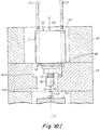
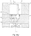
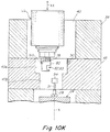
- Figs. 10H - 10M illustrate a variety of steps for decoupling the actuator from the mounting plate 39 and for decoupling the valve pin assembly 30, 94 from the actuator coupling 80 and the mounting plate 39, 45, according to one embodiment.
- the actuator is shown coupled to the valve pin assembly, with the actuator secured to the lower mounting plate and the valve pin assembly mounted in the actuator coupling.
- the mounting plates 39 45 are clamped to the mold 12 with the manifold 24 secured between the mounting plates and mold.
- Fig. 10I the bolts 77 are decoupled from the complementary receiving apertures 50 in the clamp plate 39 thus decoupling the actuator 66 housing from the clamp plate 45.
- the housing of the actuator 66 and associated neck 75 are disposed upon decoupling of the housing within the plate receiving apertures 40, 40a, 40b.
- Fig. 10J the first two steps of disassembly have been performed. The bolts have been removed and then the actuator 66 housing is moved laterally or radially in direction S so as to decouple pin connector 94 from coupling 80 by sliding the connector 94 radially 102, ( Fig. 10J ) out of the recess 82, 83 of the coupling.
- the pin stem 31 and associated parts such as the pin head 34 and adapter 94 and set screw 104 remain behind mounted to the manifold 24 while the actuator 66, is still disposed on the plate 45 and within the recesses 40, 40a, 40b of the mounting plates 39, 45.
- the actuator 66 can be removed entirely, Figs. 10K , 10L , for replacement or repair of the actuator, from the recesses 40, 40a.
- the valve pin assembly again remains stationary and behind mounted to the manifold and does not require removal of the pin 30.
- the mounting plates 39 and/or 45 can also be removed alone or together with the actuator 66 from the mold 12 once the actuator is decoupled from the pin connector 94 without requiring removal of the valve pin 30 (and pin connector 94) from the manifold or nozzle.
- the clamp plates 39, 45 can be removed from the system once the pin is decoupled from the actuator coupling 80, or the actuator 66 can removed from the system once the pin is decoupled from the actuator coupling 80, or both the plates and the actuator can be removed from the system once the pin is decoupled from the actuator coupling 80, all such removals being accomplished without removal of the pin 30 from the manifold or nozzle.
Landscapes
- Engineering & Computer Science (AREA)
- Manufacturing & Machinery (AREA)
- Mechanical Engineering (AREA)
- Injection Moulding Of Plastics Or The Like (AREA)
- Moulds For Moulding Plastics Or The Like (AREA)
- Mechanically-Actuated Valves (AREA)
- Electrically Driven Valve-Operating Means (AREA)
Claims (15)
- Appareil pour contrôler la vitesse d'écoulement d'un matériau de moulage fluide d'une machine de moulage par injection vers une cavité de moule (19), l'appareil comprenant :un collecteur (24) recevant un matériau de moulage fluide d'injection, le collecteur ayant un canal de distribution qui délivre le matériau de moulage fluide d'injection sous une pression d'injection à une porte (20) d'une cavité de moule (19) disposée à l'intérieur d'un moule (13, 14), la porte étant ouverte et fermée de manière commandable par une goupille de soupape (31) ayant un axe de goupille (X), la goupille de soupape (31) étant montée coulissante pour un mouvement linéaire alternatif vers l'amont et vers l'aval (XX) le long de l'axe de goupille (X), de sorte qu'une extrémité aval de la goupille de soupape peut être entraînée dans des positions ouverte et fermée, et hors de celles-ci, par rapport à la porte (20),un actionneur électrique (66) comprenant un moteur électrique comprenant un boîtier de moteur (64, 64a) qui loge un arbre d'entraînement (61) ayant un engrenage d'entraînement (191) et un axe d'entraînement (Y) monté rotatif (61R) dans le boîtier du moteur et qui peut être entraîné en rotation autour de l'axe d'entraînement (Y) par une source de puissance ou d'énergie électrique,incluantune transmission comprenant un arbre d'engrenage (72) monté de manière rotative dans un boîtier de transmission (58), l'arbre d'engrenage (72) ayant un axe d'engrenage (X) et un engrenage de transmission (190) pouvant être entraîné en rotation autour de l'axe d'engrenage,l'engrenage d'entraînement (191) et l'engrenage de transmission (190) étant interconnectés en entraînement et agencés de sorte que l'axe d'entraînement (Y) et l'axe d'engrenage (X) sont montés ou disposés de manière non coaxiale l'un par rapport à l'autre et qu'une rotation entraînée de l'engrenage d'entraînement (61R) autour de l'axe d'entraînement (Y) entraîne l'arbre d'engrenage (72) en rotation autour de l'axe d'engrenage (X),un convertisseur de déplacement linéaire comprenant un arbre de déplacement (197) ayant un axe de déplacement (X), l'arbre d'engrenage (72) étant interconnecté à une extrémité amont (195) du convertisseur de déplacement linéaire et la goupille de soupape (31) étant interconnectée à une extrémité aval du convertisseur de déplacement linéaire,l'interconnexion entre le convertisseur et l'arbre d'engrenage (72) étant adaptée à convertir la rotation de l'arbre d'engrenage (72R) en déplacement linéaire (XX) de l'arbre de déplacement (197) le long de l'axe de déplacement (X),le convertisseur de déplacement linéaire étant monté pour un déplacement linéaire vers l'amont et vers l'aval (XX) commandable conjointement avec la goupille de soupape (31) par l'intermédiaire de l'interconnexion de l'extrémité aval (75, 80) du convertisseur de déplacement linéaire à la goupille de soupape (31),dans lequel l'un ou l'autre du boîtier de moteur (64) ou du boîtier de transmission (58) sont fixés de manière amovible à une plaque de fixation ou de montage supérieure (39, 42) qui est montée en amont du collecteur (24) et interconnectée de manière fixe au moule (13, 14),dans lequel la goupille de soupape (31) comprend une tige de goupille et un connecteur de goupille (34, 94), le convertisseur de déplacement linéaire ayant un accouplement de goupille (80) pouvant être accouplé de manière réversible au connecteur de goupille (34, 94) et désaccouplé de celui-ci dans une direction radiale (R) par rapport à l'axe de déplacement (XX),la tige de goupille (31) s'étendant du convertisseur de déplacement linéaire dans le collecteur lorsque l'actionneur est accouplé à la plaque de serrage ou de montage supérieure (39, 42) et le connecteur de goupille (94) est reçu à l'intérieur de l'accouplement d'actionneur (80), etl'actionneur (66) étant monté sur ou à l'intérieur de la plaque de serrage ou de montage supérieure (39, 42) pour un mouvement radial (R) lors du désaccouplement de l'actionneur de la plaque de fixation ou de montage supérieure (39, 42), de sorte que le connecteur de goupille (34, 94) est désaccouplable de l'accouplement de goupille (80) lors dudit mouvement radial, tandis que l'actionneur est disposé sur ou à l'intérieur de la plaque de montage, l'actionneur étant amovible de sur ou à l'intérieur de la plaque de montage en laissant derrière la tige de soupape s'étendant dans le collecteur.
- Appareil selon la revendication 1, dans lequel le connecteur de goupille comprend un adaptateur (94) accouplé à une extrémité supérieure ou amont (34) de la tige (31), l'adaptateur étant configuré pour pouvoir être reçu de manière réversible à l'intérieur de l'accouplement (80) dans une direction radiale.
- Appareil selon la revendication 2, dans lequel l'adaptateur comprend une tête élargie (94) qui peut être accouplée de manière réversible à l'accouplement (80) et désaccouplée de celui-ci.
- Appareil selon la revendication 1, dans lequel l'appareil est adapté à permettre au connecteur de goupille (94) de parcourir une distance radiale sélectionnée à l'intérieur de l'accouplement et à rester accouplé tandis que la plaque de fixation ou de montage supérieure (39, 42) reste accouplée au moule et la tige de goupille reste étendue dans le collecteur.
- Appareil selon la revendication 1, dans lequel la tige de goupille est montée sur le collecteur pour un mouvement radial (R) de la tige de goupille (31) conjointement avec le collecteur (24) par rapport à la plaque de serrage ou de montage supérieure.
- Appareil selon la revendication 2, dans lequel l'appareil est adapté à permettre à l'adaptateur de parcourir une distance radiale sélectionnée à l'intérieur de l'accouplement par rapport au chemin axial de déplacement tandis que la plaque de montage reste accouplée au moule, le connecteur de goupille reste accouplé à l'accouplement d'actionneur et la tige de goupille reste étendue dans le collecteur.
- Appareil selon la revendication 2, dans lequel la plaque de serrage ou de montage supérieure peut être désaccouplée du moule en laissant la tige de goupille étendue dans le collecteur lorsque l'adaptateur est désaccouplé de l'accouplement.
- Appareil selon la revendication 1, dans lequel le boîtier de moteur est fixé de manière amovible à la plaque de fixation ou de montage supérieure et le boîtier de transmission est fixé de manière amovible au boîtier de moteur.
- Appareil selon la revendication 1, dans lequel le boîtier de transmission est fixé de manière amovible à la plaque de fixation ou de montage supérieure et le boîtier de moteur est fixé de manière amovible au boîtier de moteur.
- Appareil selon la revendication 1, dans lequel l'actionneur est interconnecté à un dispositif de commande qui inclut des instructions qui ordonnent à l'actionneur d'entraîner la goupille de soupape de façon continue vers l'amont en partant de la position fermée vers une ou plusieurs positions amont intermédiaires à une ou plusieurs vitesses de déplacement intermédiaires qui sont inférieures à une vitesse maximale à laquelle l'actionneur est capable d'entraîner la goupille de soupape soit pendant un laps de temps prédéterminé, soit pour une longueur prédéterminée de déplacement vers l'amont.
- Appareil selon la revendication 10, dans lequel l'actionneur inclut des instructions qui ordonnent à l'actionneur d'entraîner la goupille de soupape de façon continue vers l'amont à partir desdites une ou plusieurs positions amont intermédiaires vers une position amont maximale à une ou plusieurs vitesses de déplacement élevées qui sont égales ou supérieures auxdites une ou plusieurs vitesses de déplacement intermédiaires.
- Appareil selon la revendication 10, comprenant en outre un capteur de position qui détecte une position de l'actionneur ou de la goupille de soupape,
le capteur de position détectant la position de l'actionneur ou de la goupille de soupape et envoyant un signal indicatif de la position de l'actionneur ou la goupille de soupape au dispositif de commande ;
le dispositif de commande ordonnant à l'actionneur d'entraîner la goupille de soupape de façon continue vers l'amont à partir desdites une ou plusieurs positions amont intermédiaires auxdites une ou plusieurs vitesses de déplacement élevées lors de la détection par le capteur de position de la goupille de soupape auxdites une ou plusieurs positions amont intermédiaires. - Appareil selon la revendication 1, dans lequel l'engrenage d'entraînement et l'engrenage de transmission sont interconnectés en rotation par l'intermédiaire d'engrenages ou par l'intermédiaire d'une courroie et d'une poulie.
- Appareil selon la revendication 1, dans lequel le dispositif de commande inclut des instructions qui ordonnent à l'actionneur d'entraîner la goupille de soupape à une ou plusieurs vitesses élevées de déplacement vers l'aval qui sont égales ou inférieures à une vitesse maximale de déplacement vers l'aval à laquelle l'actionneur est capable d'entraîner la goupille de soupape lorsque la goupille de soupape est disposée à une position amont maximale au cours d'un cycle d'injection,
le dispositif de commande incluant des instructions qui ordonnent à l'actionneur d'entraîner la goupille de soupape à une ou plusieurs vitesses intermédiaires de déplacement vers l'aval qui sont inférieures auxdites une ou plusieurs vitesses de déplacement élevées vers l'aval à l'expiration d'un laps de temps prédéterminé ou pour une quantité prédéterminée de déplacement vers l'aval de la goupille de soupape à partir de la position amont maximale. - Appareil selon la revendication 14, comprenant en outre un capteur de position qui détecte une position de l'actionneur ou de la goupille de soupape,
le capteur de position détectant la position de l'actionneur ou de la goupille de soupape et envoyant un signal indicatif de la position de l'actionneur ou de la goupille de soupape au dispositif de commande ;
le dispositif de commande ordonnant à l'actionneur d'entraîner la goupille de soupape de façon continue vers l'aval auxdites une ou plusieurs vitesses intermédiaires de déplacement vers l'aval lorsque le capteur de position détecte que la goupille de soupape a parcouru la quantité prédéterminée de déplacement vers l'aval à partir de la position amont maximale.
Priority Applications (3)
| Application Number | Priority Date | Filing Date | Title |
|---|---|---|---|
| EP18207328.8A EP3488989B1 (fr) | 2013-07-08 | 2014-07-08 | Actionneur électrique et transmission montés de façon non coaxiale |
| EP18152031.3A EP3342575B2 (fr) | 2013-07-08 | 2014-07-08 | Actionneur électrique et transmission montés de façon non coaxiale |
| EP20180765.8A EP3730274B1 (fr) | 2013-07-08 | 2014-07-08 | Actionneur électrique monté de façon non coaxiale et transmission |
Applications Claiming Priority (2)
| Application Number | Priority Date | Filing Date | Title |
|---|---|---|---|
| US201361843561P | 2013-07-08 | 2013-07-08 | |
| PCT/US2014/045648 WO2015006261A1 (fr) | 2013-07-08 | 2014-07-08 | Transmission et actionneur électrique montés de manière non coaxiale |
Related Child Applications (4)
| Application Number | Title | Priority Date | Filing Date |
|---|---|---|---|
| EP20180765.8A Division EP3730274B1 (fr) | 2013-07-08 | 2014-07-08 | Actionneur électrique monté de façon non coaxiale et transmission |
| EP18207328.8A Division EP3488989B1 (fr) | 2013-07-08 | 2014-07-08 | Actionneur électrique et transmission montés de façon non coaxiale |
| EP18152031.3A Division EP3342575B2 (fr) | 2013-07-08 | 2014-07-08 | Actionneur électrique et transmission montés de façon non coaxiale |
| EP18152031.3A Division-Into EP3342575B2 (fr) | 2013-07-08 | 2014-07-08 | Actionneur électrique et transmission montés de façon non coaxiale |
Publications (2)
| Publication Number | Publication Date |
|---|---|
| EP3019323A1 EP3019323A1 (fr) | 2016-05-18 |
| EP3019323B1 true EP3019323B1 (fr) | 2018-04-04 |
Family
ID=51225095
Family Applications (4)
| Application Number | Title | Priority Date | Filing Date |
|---|---|---|---|
| EP14742706.6A Not-in-force EP3019323B1 (fr) | 2013-07-08 | 2014-07-08 | Transmission et actionneur électrique montés de manière non coaxiale |
| EP18207328.8A Not-in-force EP3488989B1 (fr) | 2013-07-08 | 2014-07-08 | Actionneur électrique et transmission montés de façon non coaxiale |
| EP18152031.3A Active EP3342575B2 (fr) | 2013-07-08 | 2014-07-08 | Actionneur électrique et transmission montés de façon non coaxiale |
| EP20180765.8A Not-in-force EP3730274B1 (fr) | 2013-07-08 | 2014-07-08 | Actionneur électrique monté de façon non coaxiale et transmission |
Family Applications After (3)
| Application Number | Title | Priority Date | Filing Date |
|---|---|---|---|
| EP18207328.8A Not-in-force EP3488989B1 (fr) | 2013-07-08 | 2014-07-08 | Actionneur électrique et transmission montés de façon non coaxiale |
| EP18152031.3A Active EP3342575B2 (fr) | 2013-07-08 | 2014-07-08 | Actionneur électrique et transmission montés de façon non coaxiale |
| EP20180765.8A Not-in-force EP3730274B1 (fr) | 2013-07-08 | 2014-07-08 | Actionneur électrique monté de façon non coaxiale et transmission |
Country Status (4)
| Country | Link |
|---|---|
| EP (4) | EP3019323B1 (fr) |
| CN (2) | CN105612039B (fr) |
| DE (1) | DE202014011323U1 (fr) |
| WO (1) | WO2015006261A1 (fr) |
Cited By (1)
| Publication number | Priority date | Publication date | Assignee | Title |
|---|---|---|---|---|
| US10543629B2 (en) | 2014-12-11 | 2020-01-28 | Inglass S.P.A. | Method and apparatus for injection molding of plastic materials |
Families Citing this family (25)
| Publication number | Priority date | Publication date | Assignee | Title |
|---|---|---|---|---|
| US10899056B2 (en) | 2011-11-23 | 2021-01-26 | Synventive Molding Solutions, Inc. | Non-coaxially mounted electric actuator and transmission |
| EP3326776B1 (fr) * | 2014-03-10 | 2019-12-25 | Inglass S.p.A. | Plaque de fixation du moule d'un appareil de moulage par injection de matière plastique |
| US11007695B2 (en) | 2015-03-20 | 2021-05-18 | Synventive Molding Solutions, Inc. | Actuator cooling apparatus and method |
| WO2019100085A1 (fr) | 2017-11-14 | 2019-05-23 | Synventive Molding Solutions, Inc. | Actionneur doté d'un entraînement de cheville excentrique |
| WO2018089243A1 (fr) * | 2016-11-14 | 2018-05-17 | Synventive Molding Solutions, Inc. | Appareil et procédé de refroidissement d'actionneur |
| ITUB20156839A1 (it) | 2015-12-10 | 2017-06-10 | Inglass Spa | Apparecchiatura di stampaggio ad iniezione di materie plastiche |
| WO2017210169A1 (fr) | 2016-06-01 | 2017-12-07 | Synventive Molding Solutions, Inc. | Ensemble dispositif de commande pour un système de moulage par injection |
| CN110337355B (zh) * | 2017-01-05 | 2022-05-20 | 圣万提注塑工业(苏州)有限公司 | 驱动注塑成型设备中阀销的远程安装的电动马达 |
| WO2018169819A1 (fr) | 2017-03-16 | 2018-09-20 | Synventive Molding Solutions, Inc. | Appareil de moulage par injection |
| WO2018175362A1 (fr) | 2017-03-20 | 2018-09-27 | Synventive Molding Solutions, Inc. | Procédé et appareil de commande de positions et de vitesse d'aiguille d'obturateur |
| WO2018183810A1 (fr) | 2017-03-31 | 2018-10-04 | Synventive Molding Solutions, Inc. | Vanne rotative |
| CN110461566B (zh) | 2017-04-18 | 2022-01-11 | 圣万提注塑工业(苏州)有限公司 | 注射循环期间的线性到线性阀销驱动 |
| CN110520269B (zh) | 2017-04-26 | 2021-11-30 | 圣万提注塑工业(苏州)有限公司 | 具有排气口的双密封阀销尖端 |
| CN113165240B (zh) | 2018-08-17 | 2023-03-28 | 圣万提注塑工业(苏州)有限公司 | 穿过注射成型流动通道的中断流 |
| WO2020176479A1 (fr) | 2019-02-25 | 2020-09-03 | Synventive Molding Solutions, Inc. | Injection commandée par actionneur électrique refroidi |
| US20200316837A1 (en) | 2019-04-02 | 2020-10-08 | Synventive Molding Solutions, Inc. | Nozzle Heater |
| CN114025936B (zh) | 2019-05-28 | 2022-11-29 | 圣万提注塑工业(苏州)有限公司 | 用于阀销的部分旋转偏心驱动 |
| CN113811431B (zh) | 2019-08-20 | 2023-10-13 | 圣万提注塑工业(苏州)有限公司 | 具有集成致动器电子驱动装置的注射成型设备 |
| WO2021080767A1 (fr) | 2019-10-21 | 2021-04-29 | Synventive Molding Solutions, Inc. | Pilote d'actionneur électrique pour la commande d'écoulement d'un moulage par injection |
| EP4103387A1 (fr) | 2020-02-20 | 2022-12-21 | Synventive Molding Solutions, Inc. | Injection séquentielle dans de multiples cavités de moule |
| EP4175812A1 (fr) | 2020-07-01 | 2023-05-10 | Synventive Molding Solutions, Inc. | Méthode et appareil pour contrôler un écoulement de fluide d'injection |
| WO2022076782A1 (fr) | 2020-10-09 | 2022-04-14 | Synventive Molding Solutions, Inc. | Goupille de soupape amortie par ressort |
| CN116685451A (zh) | 2020-12-08 | 2023-09-01 | 圣万提注塑工业有限公司 | 带有冷却集成执行器电驱动器的注射成型装置 |
| CN116123335A (zh) * | 2022-12-01 | 2023-05-16 | 圣万提注塑工业(苏州)有限公司 | 一种热流道系统的阀针用驱动机构 |
| DE102024104166A1 (de) * | 2024-02-14 | 2025-08-14 | Günther Heisskanaltechnik Gmbh | Strömungselement für ein Spritzgusssystem |
Family Cites Families (13)
| Publication number | Priority date | Publication date | Assignee | Title |
|---|---|---|---|---|
| JP2665112B2 (ja) | 1992-08-25 | 1997-10-22 | 本田技研工業株式会社 | 射出成形方法及び射出成形装置 |
| US6294122B1 (en) | 1998-06-26 | 2001-09-25 | Synventive Molding Solutions, Inc. | Electric actuator for a melt flow control pin |
| DE19857735B4 (de) | 1998-12-15 | 2004-03-04 | Möser, Hansjürgen | Stell- und Regelvorrichtung für einen Heiß- oder Kaltkanal eines Kunststoff-Formwerkzeuges |
| CA2261367C (fr) | 1999-02-08 | 2008-04-22 | Mold-Masters Limited | Mecanisme d'actionnement d'elements de robinet de moulage par injection |
| DE19956215C2 (de) | 1999-11-23 | 2003-09-18 | Otto Maenner Heiskanalsysteme | Heißkanal-Nadelverschluß-Düse mit einem Antrieb zum Verstellen der Verschlußnadel |
| FR2850319B1 (fr) | 2003-01-24 | 2005-03-04 | Essilor Int | Procede de remplissage d'un moule avec une matiere organique a l'etat liquide en vue du moulage d'un element optique et procede de moulage incluant ce procede de remplissage |
| DE102007053044B3 (de) | 2007-11-05 | 2009-06-10 | Exaflow Gmbh & Co. Kg | Gewindekernausschraubvorrichtung für Spritzgiesswerkzeuge |
| JP5080324B2 (ja) | 2008-02-15 | 2012-11-21 | 第一実業株式会社 | 射出成形用ホットランナ金型のバルブゲート |
| DE102009012082B3 (de) | 2009-03-06 | 2010-10-28 | Incoe International, Inc. | Verfahren zum Spritzgießen, insbesondere zum Kaskadenspritzgießen, und Vorrichtung zur Durchführung des Verfahrens |
| US8091202B2 (en) * | 2009-05-06 | 2012-01-10 | Synventive Molding Solutions, Inc. | Method and apparatus for coupling and uncoupling an injection valve pin |
| WO2010128984A1 (fr) * | 2009-05-06 | 2010-11-11 | Synventive Molding Solutions, Inc. | Coupleur |
| CN103249538B (zh) | 2010-11-23 | 2015-08-26 | 圣万提注塑工业有限公司 | 注塑成型流动控制装置及方法 |
| ITTO20120578A1 (it) | 2012-06-28 | 2013-12-29 | Inglass Spa | Apparecchiatura di stampaggio ad iniezione di materie plastiche |
-
2014
- 2014-07-08 EP EP14742706.6A patent/EP3019323B1/fr not_active Not-in-force
- 2014-07-08 EP EP18207328.8A patent/EP3488989B1/fr not_active Not-in-force
- 2014-07-08 EP EP18152031.3A patent/EP3342575B2/fr active Active
- 2014-07-08 CN CN201480049316.8A patent/CN105612039B/zh not_active Expired - Fee Related
- 2014-07-08 DE DE202014011323.8U patent/DE202014011323U1/de not_active Expired - Lifetime
- 2014-07-08 EP EP20180765.8A patent/EP3730274B1/fr not_active Not-in-force
- 2014-07-08 WO PCT/US2014/045648 patent/WO2015006261A1/fr not_active Ceased
- 2014-07-08 CN CN201710032491.1A patent/CN106738673B/zh active Active
Cited By (1)
| Publication number | Priority date | Publication date | Assignee | Title |
|---|---|---|---|---|
| US10543629B2 (en) | 2014-12-11 | 2020-01-28 | Inglass S.P.A. | Method and apparatus for injection molding of plastic materials |
Also Published As
| Publication number | Publication date |
|---|---|
| CN105612039A (zh) | 2016-05-25 |
| EP3342575B1 (fr) | 2019-09-25 |
| EP3730274A1 (fr) | 2020-10-28 |
| DE202014011323U1 (de) | 2019-05-09 |
| CN105612039B (zh) | 2018-05-01 |
| EP3730274B1 (fr) | 2021-09-01 |
| EP3342575B2 (fr) | 2022-11-16 |
| CN106738673B (zh) | 2020-02-07 |
| EP3019323A1 (fr) | 2016-05-18 |
| EP3488989A1 (fr) | 2019-05-29 |
| WO2015006261A1 (fr) | 2015-01-15 |
| CN106738673A (zh) | 2017-05-31 |
| EP3342575A1 (fr) | 2018-07-04 |
| EP3488989B1 (fr) | 2020-12-09 |
Similar Documents
| Publication | Publication Date | Title |
|---|---|---|
| EP3019323B1 (fr) | Transmission et actionneur électrique montés de manière non coaxiale | |
| US9937648B2 (en) | Non-coaxially mounted electric actuator and transmission | |
| US11007692B1 (en) | Non-coaxially mounted electric actuator and transmission | |
| US8282388B2 (en) | Apparatus for coupling and uncoupling an injection valve pin | |
| EP3380295B1 (fr) | Transmission par câble de commande d'actionneur pour système de moulage par injection | |
| EP3565698B1 (fr) | Moteur électrique monté à distance, entraînant une tige de soupape dans un appareil de moulage par injection | |
| EP2427318B1 (fr) | Appareil d'accouplement et procédé associé | |
| CN114502349B (zh) | 具有在内部冷却的轴向安装的电动致动器的热流道组件 | |
| US20150110917A1 (en) | Side actuated shooting pot | |
| CA2607311C (fr) | Piece rapportee pour cylindre a piston de rotor |
Legal Events
| Date | Code | Title | Description |
|---|---|---|---|
| PUAI | Public reference made under article 153(3) epc to a published international application that has entered the european phase |
Free format text: ORIGINAL CODE: 0009012 |
|
| 17P | Request for examination filed |
Effective date: 20160203 |
|
| AK | Designated contracting states |
Kind code of ref document: A1 Designated state(s): AL AT BE BG CH CY CZ DE DK EE ES FI FR GB GR HR HU IE IS IT LI LT LU LV MC MK MT NL NO PL PT RO RS SE SI SK SM TR |
|
| AX | Request for extension of the european patent |
Extension state: BA ME |
|
| DAX | Request for extension of the european patent (deleted) | ||
| STAA | Information on the status of an ep patent application or granted ep patent |
Free format text: STATUS: EXAMINATION IS IN PROGRESS |
|
| 17Q | First examination report despatched |
Effective date: 20170113 |
|
| GRAP | Despatch of communication of intention to grant a patent |
Free format text: ORIGINAL CODE: EPIDOSNIGR1 |
|
| STAA | Information on the status of an ep patent application or granted ep patent |
Free format text: STATUS: GRANT OF PATENT IS INTENDED |
|
| INTG | Intention to grant announced |
Effective date: 20171122 |
|
| GRAS | Grant fee paid |
Free format text: ORIGINAL CODE: EPIDOSNIGR3 |
|
| GRAA | (expected) grant |
Free format text: ORIGINAL CODE: 0009210 |
|
| STAA | Information on the status of an ep patent application or granted ep patent |
Free format text: STATUS: THE PATENT HAS BEEN GRANTED |
|
| AK | Designated contracting states |
Kind code of ref document: B1 Designated state(s): AL AT BE BG CH CY CZ DE DK EE ES FI FR GB GR HR HU IE IS IT LI LT LU LV MC MK MT NL NO PL PT RO RS SE SI SK SM TR |
|
| REG | Reference to a national code |
Ref country code: GB Ref legal event code: FG4D |
|
| REG | Reference to a national code |
Ref country code: CH Ref legal event code: EP |
|
| REG | Reference to a national code |
Ref country code: AT Ref legal event code: REF Ref document number: 985127 Country of ref document: AT Kind code of ref document: T Effective date: 20180415 |
|
| REG | Reference to a national code |
Ref country code: IE Ref legal event code: FG4D |
|
| REG | Reference to a national code |
Ref country code: DE Ref legal event code: R096 Ref document number: 602014023345 Country of ref document: DE |
|
| REG | Reference to a national code |
Ref country code: FR Ref legal event code: PLFP Year of fee payment: 5 |
|
| REG | Reference to a national code |
Ref country code: NL Ref legal event code: MP Effective date: 20180404 |
|
| REG | Reference to a national code |
Ref country code: LT Ref legal event code: MG4D |
|
| PG25 | Lapsed in a contracting state [announced via postgrant information from national office to epo] |
Ref country code: NL Free format text: LAPSE BECAUSE OF FAILURE TO SUBMIT A TRANSLATION OF THE DESCRIPTION OR TO PAY THE FEE WITHIN THE PRESCRIBED TIME-LIMIT Effective date: 20180404 |
|
| PG25 | Lapsed in a contracting state [announced via postgrant information from national office to epo] |
Ref country code: BG Free format text: LAPSE BECAUSE OF FAILURE TO SUBMIT A TRANSLATION OF THE DESCRIPTION OR TO PAY THE FEE WITHIN THE PRESCRIBED TIME-LIMIT Effective date: 20180704 Ref country code: SE Free format text: LAPSE BECAUSE OF FAILURE TO SUBMIT A TRANSLATION OF THE DESCRIPTION OR TO PAY THE FEE WITHIN THE PRESCRIBED TIME-LIMIT Effective date: 20180404 Ref country code: PL Free format text: LAPSE BECAUSE OF FAILURE TO SUBMIT A TRANSLATION OF THE DESCRIPTION OR TO PAY THE FEE WITHIN THE PRESCRIBED TIME-LIMIT Effective date: 20180404 Ref country code: ES Free format text: LAPSE BECAUSE OF FAILURE TO SUBMIT A TRANSLATION OF THE DESCRIPTION OR TO PAY THE FEE WITHIN THE PRESCRIBED TIME-LIMIT Effective date: 20180404 Ref country code: LT Free format text: LAPSE BECAUSE OF FAILURE TO SUBMIT A TRANSLATION OF THE DESCRIPTION OR TO PAY THE FEE WITHIN THE PRESCRIBED TIME-LIMIT Effective date: 20180404 Ref country code: NO Free format text: LAPSE BECAUSE OF FAILURE TO SUBMIT A TRANSLATION OF THE DESCRIPTION OR TO PAY THE FEE WITHIN THE PRESCRIBED TIME-LIMIT Effective date: 20180704 Ref country code: FI Free format text: LAPSE BECAUSE OF FAILURE TO SUBMIT A TRANSLATION OF THE DESCRIPTION OR TO PAY THE FEE WITHIN THE PRESCRIBED TIME-LIMIT Effective date: 20180404 Ref country code: AL Free format text: LAPSE BECAUSE OF FAILURE TO SUBMIT A TRANSLATION OF THE DESCRIPTION OR TO PAY THE FEE WITHIN THE PRESCRIBED TIME-LIMIT Effective date: 20180404 |
|
| PG25 | Lapsed in a contracting state [announced via postgrant information from national office to epo] |
Ref country code: HR Free format text: LAPSE BECAUSE OF FAILURE TO SUBMIT A TRANSLATION OF THE DESCRIPTION OR TO PAY THE FEE WITHIN THE PRESCRIBED TIME-LIMIT Effective date: 20180404 Ref country code: RS Free format text: LAPSE BECAUSE OF FAILURE TO SUBMIT A TRANSLATION OF THE DESCRIPTION OR TO PAY THE FEE WITHIN THE PRESCRIBED TIME-LIMIT Effective date: 20180404 Ref country code: GR Free format text: LAPSE BECAUSE OF FAILURE TO SUBMIT A TRANSLATION OF THE DESCRIPTION OR TO PAY THE FEE WITHIN THE PRESCRIBED TIME-LIMIT Effective date: 20180705 Ref country code: LV Free format text: LAPSE BECAUSE OF FAILURE TO SUBMIT A TRANSLATION OF THE DESCRIPTION OR TO PAY THE FEE WITHIN THE PRESCRIBED TIME-LIMIT Effective date: 20180404 |
|
| REG | Reference to a national code |
Ref country code: AT Ref legal event code: MK05 Ref document number: 985127 Country of ref document: AT Kind code of ref document: T Effective date: 20180404 |
|
| PG25 | Lapsed in a contracting state [announced via postgrant information from national office to epo] |
Ref country code: PT Free format text: LAPSE BECAUSE OF FAILURE TO SUBMIT A TRANSLATION OF THE DESCRIPTION OR TO PAY THE FEE WITHIN THE PRESCRIBED TIME-LIMIT Effective date: 20180806 |
|
| REG | Reference to a national code |
Ref country code: DE Ref legal event code: R097 Ref document number: 602014023345 Country of ref document: DE |
|
| PG25 | Lapsed in a contracting state [announced via postgrant information from national office to epo] |
Ref country code: RO Free format text: LAPSE BECAUSE OF FAILURE TO SUBMIT A TRANSLATION OF THE DESCRIPTION OR TO PAY THE FEE WITHIN THE PRESCRIBED TIME-LIMIT Effective date: 20180404 Ref country code: SK Free format text: LAPSE BECAUSE OF FAILURE TO SUBMIT A TRANSLATION OF THE DESCRIPTION OR TO PAY THE FEE WITHIN THE PRESCRIBED TIME-LIMIT Effective date: 20180404 Ref country code: CZ Free format text: LAPSE BECAUSE OF FAILURE TO SUBMIT A TRANSLATION OF THE DESCRIPTION OR TO PAY THE FEE WITHIN THE PRESCRIBED TIME-LIMIT Effective date: 20180404 Ref country code: AT Free format text: LAPSE BECAUSE OF FAILURE TO SUBMIT A TRANSLATION OF THE DESCRIPTION OR TO PAY THE FEE WITHIN THE PRESCRIBED TIME-LIMIT Effective date: 20180404 Ref country code: EE Free format text: LAPSE BECAUSE OF FAILURE TO SUBMIT A TRANSLATION OF THE DESCRIPTION OR TO PAY THE FEE WITHIN THE PRESCRIBED TIME-LIMIT Effective date: 20180404 Ref country code: DK Free format text: LAPSE BECAUSE OF FAILURE TO SUBMIT A TRANSLATION OF THE DESCRIPTION OR TO PAY THE FEE WITHIN THE PRESCRIBED TIME-LIMIT Effective date: 20180404 |
|
| PLBE | No opposition filed within time limit |
Free format text: ORIGINAL CODE: 0009261 |
|
| STAA | Information on the status of an ep patent application or granted ep patent |
Free format text: STATUS: NO OPPOSITION FILED WITHIN TIME LIMIT |
|
| PG25 | Lapsed in a contracting state [announced via postgrant information from national office to epo] |
Ref country code: SM Free format text: LAPSE BECAUSE OF FAILURE TO SUBMIT A TRANSLATION OF THE DESCRIPTION OR TO PAY THE FEE WITHIN THE PRESCRIBED TIME-LIMIT Effective date: 20180404 |
|
| REG | Reference to a national code |
Ref country code: CH Ref legal event code: PL |
|
| 26N | No opposition filed |
Effective date: 20190107 |
|
| PG25 | Lapsed in a contracting state [announced via postgrant information from national office to epo] |
Ref country code: MC Free format text: LAPSE BECAUSE OF FAILURE TO SUBMIT A TRANSLATION OF THE DESCRIPTION OR TO PAY THE FEE WITHIN THE PRESCRIBED TIME-LIMIT Effective date: 20180404 Ref country code: LU Free format text: LAPSE BECAUSE OF NON-PAYMENT OF DUE FEES Effective date: 20180708 |
|
| REG | Reference to a national code |
Ref country code: BE Ref legal event code: MM Effective date: 20180731 |
|
| REG | Reference to a national code |
Ref country code: IE Ref legal event code: MM4A |
|
| PG25 | Lapsed in a contracting state [announced via postgrant information from national office to epo] |
Ref country code: IE Free format text: LAPSE BECAUSE OF NON-PAYMENT OF DUE FEES Effective date: 20180708 Ref country code: CH Free format text: LAPSE BECAUSE OF NON-PAYMENT OF DUE FEES Effective date: 20180731 Ref country code: LI Free format text: LAPSE BECAUSE OF NON-PAYMENT OF DUE FEES Effective date: 20180731 |
|
| PG25 | Lapsed in a contracting state [announced via postgrant information from national office to epo] |
Ref country code: SI Free format text: LAPSE BECAUSE OF FAILURE TO SUBMIT A TRANSLATION OF THE DESCRIPTION OR TO PAY THE FEE WITHIN THE PRESCRIBED TIME-LIMIT Effective date: 20180404 Ref country code: BE Free format text: LAPSE BECAUSE OF NON-PAYMENT OF DUE FEES Effective date: 20180731 |
|
| PG25 | Lapsed in a contracting state [announced via postgrant information from national office to epo] |
Ref country code: MT Free format text: LAPSE BECAUSE OF NON-PAYMENT OF DUE FEES Effective date: 20180708 |
|
| PG25 | Lapsed in a contracting state [announced via postgrant information from national office to epo] |
Ref country code: TR Free format text: LAPSE BECAUSE OF FAILURE TO SUBMIT A TRANSLATION OF THE DESCRIPTION OR TO PAY THE FEE WITHIN THE PRESCRIBED TIME-LIMIT Effective date: 20180404 |
|
| PG25 | Lapsed in a contracting state [announced via postgrant information from national office to epo] |
Ref country code: HU Free format text: LAPSE BECAUSE OF FAILURE TO SUBMIT A TRANSLATION OF THE DESCRIPTION OR TO PAY THE FEE WITHIN THE PRESCRIBED TIME-LIMIT; INVALID AB INITIO Effective date: 20140708 Ref country code: MK Free format text: LAPSE BECAUSE OF NON-PAYMENT OF DUE FEES Effective date: 20180404 Ref country code: CY Free format text: LAPSE BECAUSE OF FAILURE TO SUBMIT A TRANSLATION OF THE DESCRIPTION OR TO PAY THE FEE WITHIN THE PRESCRIBED TIME-LIMIT Effective date: 20180404 |
|
| PG25 | Lapsed in a contracting state [announced via postgrant information from national office to epo] |
Ref country code: IS Free format text: LAPSE BECAUSE OF FAILURE TO SUBMIT A TRANSLATION OF THE DESCRIPTION OR TO PAY THE FEE WITHIN THE PRESCRIBED TIME-LIMIT Effective date: 20180804 |
|
| PGFP | Annual fee paid to national office [announced via postgrant information from national office to epo] |
Ref country code: IT Payment date: 20210721 Year of fee payment: 8 Ref country code: FR Payment date: 20210726 Year of fee payment: 8 |
|
| PGFP | Annual fee paid to national office [announced via postgrant information from national office to epo] |
Ref country code: GB Payment date: 20210727 Year of fee payment: 8 Ref country code: DE Payment date: 20210728 Year of fee payment: 8 |
|
| REG | Reference to a national code |
Ref country code: DE Ref legal event code: R119 Ref document number: 602014023345 Country of ref document: DE |
|
| GBPC | Gb: european patent ceased through non-payment of renewal fee |
Effective date: 20220708 |
|
| PG25 | Lapsed in a contracting state [announced via postgrant information from national office to epo] |
Ref country code: FR Free format text: LAPSE BECAUSE OF NON-PAYMENT OF DUE FEES Effective date: 20220731 |
|
| PG25 | Lapsed in a contracting state [announced via postgrant information from national office to epo] |
Ref country code: GB Free format text: LAPSE BECAUSE OF NON-PAYMENT OF DUE FEES Effective date: 20220708 Ref country code: DE Free format text: LAPSE BECAUSE OF NON-PAYMENT OF DUE FEES Effective date: 20230201 |
|
| PG25 | Lapsed in a contracting state [announced via postgrant information from national office to epo] |
Ref country code: IT Free format text: LAPSE BECAUSE OF NON-PAYMENT OF DUE FEES Effective date: 20220708 |