EP3019683B1 - Patte d'une penture - Google Patents
Patte d'une penture Download PDFInfo
- Publication number
- EP3019683B1 EP3019683B1 EP14711503.4A EP14711503A EP3019683B1 EP 3019683 B1 EP3019683 B1 EP 3019683B1 EP 14711503 A EP14711503 A EP 14711503A EP 3019683 B1 EP3019683 B1 EP 3019683B1
- Authority
- EP
- European Patent Office
- Prior art keywords
- bushing
- hinge
- detent
- key surface
- counter
- Prior art date
- Legal status (The legal status is an assumption and is not a legal conclusion. Google has not performed a legal analysis and makes no representation as to the accuracy of the status listed.)
- Active
Links
Images


Classifications
-
- E—FIXED CONSTRUCTIONS
- E05—LOCKS; KEYS; WINDOW OR DOOR FITTINGS; SAFES
- E05D—HINGES OR SUSPENSION DEVICES FOR DOORS, WINDOWS OR WINGS
- E05D3/00—Hinges with pins
- E05D3/02—Hinges with pins with one pin
-
- E—FIXED CONSTRUCTIONS
- E05—LOCKS; KEYS; WINDOW OR DOOR FITTINGS; SAFES
- E05D—HINGES OR SUSPENSION DEVICES FOR DOORS, WINDOWS OR WINGS
- E05D7/00—Hinges or pivots of special construction
- E05D7/0009—Adjustable hinges
- E05D7/0018—Adjustable hinges at the hinge axis
- E05D7/0027—Adjustable hinges at the hinge axis in an axial direction
-
- E—FIXED CONSTRUCTIONS
- E05—LOCKS; KEYS; WINDOW OR DOOR FITTINGS; SAFES
- E05D—HINGES OR SUSPENSION DEVICES FOR DOORS, WINDOWS OR WINGS
- E05D7/00—Hinges or pivots of special construction
- E05D7/0009—Adjustable hinges
- E05D7/0018—Adjustable hinges at the hinge axis
- E05D7/0045—Adjustable hinges at the hinge axis in a radial direction
- E05D7/0054—Adjustable hinges at the hinge axis in a radial direction by means of eccentric parts
-
- E—FIXED CONSTRUCTIONS
- E05—LOCKS; KEYS; WINDOW OR DOOR FITTINGS; SAFES
- E05D—HINGES OR SUSPENSION DEVICES FOR DOORS, WINDOWS OR WINGS
- E05D5/00—Construction of single parts, e.g. the parts for attachment
- E05D5/10—Pins, sockets or sleeves; Removable pins
- E05D5/14—Construction of sockets or sleeves
-
- E—FIXED CONSTRUCTIONS
- E05—LOCKS; KEYS; WINDOW OR DOOR FITTINGS; SAFES
- E05D—HINGES OR SUSPENSION DEVICES FOR DOORS, WINDOWS OR WINGS
- E05D7/00—Hinges or pivots of special construction
-
- E—FIXED CONSTRUCTIONS
- E05—LOCKS; KEYS; WINDOW OR DOOR FITTINGS; SAFES
- E05Y—INDEXING SCHEME ASSOCIATED WITH SUBCLASSES E05D AND E05F, RELATING TO CONSTRUCTION ELEMENTS, ELECTRIC CONTROL, POWER SUPPLY, POWER SIGNAL OR TRANSMISSION, USER INTERFACES, MOUNTING OR COUPLING, DETAILS, ACCESSORIES, AUXILIARY OPERATIONS NOT OTHERWISE PROVIDED FOR, APPLICATION THEREOF
- E05Y2800/00—Details, accessories and auxiliary operations not otherwise provided for
- E05Y2800/73—Multiple functions
-
- E—FIXED CONSTRUCTIONS
- E05—LOCKS; KEYS; WINDOW OR DOOR FITTINGS; SAFES
- E05Y—INDEXING SCHEME ASSOCIATED WITH SUBCLASSES E05D AND E05F, RELATING TO CONSTRUCTION ELEMENTS, ELECTRIC CONTROL, POWER SUPPLY, POWER SIGNAL OR TRANSMISSION, USER INTERFACES, MOUNTING OR COUPLING, DETAILS, ACCESSORIES, AUXILIARY OPERATIONS NOT OTHERWISE PROVIDED FOR, APPLICATION THEREOF
- E05Y2900/00—Application of doors, windows, wings or fittings thereof
- E05Y2900/10—Application of doors, windows, wings or fittings thereof for buildings or parts thereof
- E05Y2900/13—Type of wing
- E05Y2900/132—Doors
Definitions
- the lifting spindle on which the bearing bush and / or the hinge pin are supported, must be completely unscrewed while sacrificing the height adjustment.
- a separately vorzuhaltendes rotary tool can be used to rotate the bearing bush in the longitudinal recess, and from a center position by up to + / - 90 °.
- the new height adjustment takes place in that the lifting spindle is screwed as far into the longitudinal recess until the bearing bush and / or the hinge pin supporting, other hinge tabs for the correct height adjustment of the wing in the Frame has reached the required position.
- EP 0 860 571 A1 and EP 2 402 533 A2 also disclose a hinge strap with a rotatable and liftable bushing.
- the invention is therefore based on the object to provide an improved hinge strap.
- the lifting spindle is therefore used as a turning tool itself. It is therefore effectively avoided that a Dichtungsan horreingna is impossible due to the lack of a suitable turning tool.
- the hinge pin can be in the form of a straight component be formed over its entire length constant, circular cross-section.
- a key face is provided on the bearing bush and a counter key face which can be brought into operative connection with the key face is provided on the lifting spindle. If the mating key surface is located on the opposite side of the lifting spindle from the support side, the lifting spindle can be used in their function as a turning tool by first completely unscrewed from the longitudinal recess and vice versa, i. now facing away from the bearing bush and / or the hinge pin with the support side, is attached to the bearing bush. If the external thread of the lifting spindle is outside the longitudinal recess, it can now form the handle of the turning tool.
- the longitudinal recess has at least one radial detent recess.
- at the bearing bush preferably at least one locking projection is provided which can be brought into operative connection with the latching recess. If only a single detent recess and a single detent projection are provided, then these are preferably arranged such that they are in operative connection in the middle position, i. the locking defines the middle position, from which the bearing bush can be rotated by +/- 90 °.
- a plurality of locking recesses and locking projections are provided, for example, arranged offset by 90 ° or 45 ° about the axis of rotation. A snap takes place at a rotation of the bearing bush in the longitudinal recess then every 90 ° or every 45 °, whereby exactly defined positions of the bearing bush are easier to find and maintain.
- the hinge flap according to the invention is designed such that the at least one latching projection is locked in operative connection with the at least one latching recess when the bearing bush and / or the hinge bolt in indirectly or immediate contact with the support side. This prevents that during a rotation of the lifting spindle for the purpose of height adjustment, the bearing bush rotates undesirable, which would otherwise lead to an undesirable change in Dichtan horrs.
- the lifting spindle can have an annular projection surrounding the support side, which engages behind the at least one latching projection when the bearing bush and / or the hinge bolt are in direct or indirect contact with the support side.
- an annular rim may be provided which engages in a provided on the bearing bush or formed between the bearing bush and the hinge part annular groove when the key and the counter key surfaces are in operative connection. Due to this measure, the "seat" of the lifting spindle on the bearing bush, when the lifting spindle serves as a rotation aid, can be improved against unwanted loosening during the turning process.
- the edge and the bearing bushing can comprise means for transmitting torques between the edge and the bearing bush.
- the means may be operatively connected by at least one protrusion provided on the edge or at least one recess provided on the edge and by at least one complementary recess or at least one complementary protrusion of the bearing bush when the key and counter key surfaces are engaged.
- the lifting spindle can not automatically solve their function as a rotary tool from the bearing bush, a locking device and on the bearing bush a counter-locking device are preferably provided on the side of the mating key surface.
- the latching device may be a latching projection and the mating latching device may be a latching recess, such that the lifting spindle can be placed under overcoming a latching force on the bearing bushing by engaging the key surface and mating key surface or separating the key surface and mating key surface from the bearing bushing.
- the latching projection extends radially outwards from the counterkey surface.
- the counter-latching recess can be provided in the contour of the bearing bush forming the key surface.
- the counter-locking devices are preferably arranged in certain angular relationships to the lateral offset of the longitudinal axis and the axis of rotation. If, for example, the bearing bushing is in a predefined "zero position" when the band strap is delivered, then the user is unambiguously given the orientation in which the counter-locking devices are located.
- the lifting spindle in its function as a rotation aid can then be placed specifically without failures, even if due to the installation situation, the front end of the bearing bush on which the lifting spindle is placed, can not be optically detected.
- the direction of this lateral offset is preferably on the side facing away from the key surface end face of the bearing bush optically highlighted by a first mark.
- At least one second marking is provided on the support side of the lifting spindle, which is arranged in a certain angular relationship to the latching device. Due to this measure, the placement of the lifting spindle is facilitated in its function as a rotary tool on the bearing bush again.
- the exemplary embodiment of a hinge strap 100 according to the invention shown in the drawing is part of a hinge hinge-hinged about a hinge axis S connection of a wing, not shown, to a frame.
- the hinge flap 100 is shown as a frame hinge flap.
- the hinge part 2 comprises a longitudinal recess 3, in which a bearing bush 4 is provided.
- the latter is rotatably arranged about an axis of rotation D parallel to the hinge axis S, but laterally offset, by means of a rotary auxiliary means to be described in detail below.
- the bearing bush 4 has a Lagerbuchsenausnaturalung 5 with a longitudinal axis T, which is laterally offset from the axis of rotation D and coincides with the hinge axis S in the illustrated embodiment.
- the Lagerbuchsenausnaturalung 5 is in other words arranged centrally with respect to the effective outer periphery of the bearing bush 4. With “effective outer circumference” is the outer periphery which defines the axis of rotation D of the bearing bush 4 in the longitudinal recess 3.
- an internal thread 7 is provided in the longitudinal recess 3.
- this internal thread 7 - based on the operating position of the hinge strap - from below a lifting spindle 6, which has a female thread 7 to the complementary external thread 8, screwed.
- the lifting spindle 6 points to its in the in Fig. 1 to 7 illustrated operating position upper, the bearing bush 4 side facing a support side 9, on which the bearing bush 4 is supported.
- the support side 9 is surrounded by an annular projection 10th
- the bearing bush 4 can be in the longitudinal recess 3 of the hinge part 2 in the direction of the arrow P relocate by the lifting spindle 6 is further screwed from below into the longitudinal recess 3 or further unscrewed down.
- the lifting spindle has a measure for applying a rotary tool, which is designed as a hexagon socket 11 in the illustrated embodiment.
- the bearing bush recess 5 is arranged eccentrically to the effective outer circumference of the bearing bush 4. If the bearing bushing 4 is rotated within the longitudinal recess 3, then the longitudinal axis T and thus the hinge axis S is displaced relative to the hinge part 2. As a result, the other hinge tabs - in this case the hinge hinge tabs - are displaced relative to the hinge tab 100 perpendicular to the axis of rotation D. whereby, for example, a seal pressure change can be achieved.
- an edge 15 surrounding the counter key surface 14 is provided, which engages in an annular groove 16 provided on the bearing bush 4.
- Fig. 3 As in particular in Fig. 3 can be seen, are distributed in the longitudinal recess 3 over the circumference, offset by 90 ° to each other, four radial locking recesses 17 are provided.
- Complementary latching projections 18 are also provided offset by 90 ° to one another on the bearing bush 4. The locking projections 18 are elastically formed so that they shift back and release the rotation of the bearing bush 4 in the longitudinal assembly 3 when a certain torque is exceeded.
- the latching projections 18 are designed such that they are engaged behind by the annular projection 10 of the lifting spindle 6 when it is screwed into the internal thread 7 in its operating position in which the bearing bush 4 is supported on the support side 9. Because of this measure, it is reliably prevented that the bearing bush 4 can rotate within the longitudinal recess 3, if due to a frictional connection by supporting on the support side 9 of the lifting spindle 6, a torque is exerted on the bearing bush 4 during a consultnjustiervorganges in the direction P.
- Fig. 15 shows a further embodiment of a lifting spindle 6. It differs from the lifting spindle 6 in that four inwardly directed projections 19 are provided on the edge 15, which in complementary recesses 20 (s. Fig. 10 ) engage the bushing 4 when the lifting spindle 6 serves as a rotation aid for rotational actuation of the bearing bush 4.
- the maximum torque which can be transmitted through the lifting spindle 6 on the bearing bush 4, can be increased.
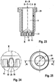
- FIG. 16 to 20 Another embodiment of a lifting spindle 6 is in the Fig. 16 to 20 shown. To avoid repetition, only the differences from the first embodiment described above are mentioned below. The description of the first embodiment is hereby fully incorporated by reference.
- the counter key surface 14 is not formed as an external hexagon, but gear-like. Between the counter-key surface 14 and the edge 15 extend with respect to the rotation axis D opposite one another latching projections 23 which form part of a arranged on the side of the mating key surface latching device 21.
- the locking projections 23 in the direction of the rotation axis D slightly over the edge 15 via. It has a "bulbous" shape in cross-section, in order to interact with a provided in the bearing bush 4 mating latching means 22 latching, as will be described below.
- bearing bush for use together with in Fig. 16 to 20 shown, bearing bush comprises an outer part 29 made of a dimensionally stable plastic, in which an inner part 30 is inserted from a friction-reducing plastic for supporting a hinge pin, not shown in the drawing.
- lower end comprises the bearing bush 4 in further difference from the particular with reference to Fig. 1 and 3 described embodiment, a key surface 13 which is approximately complementary to the counter key surface 14 and thus formed like a ring gear.
- a counter-latching device 22 for the latching device 21 of the lifting spindle 6 is formed in the contour 31 forming the wrench surface 13.
- the counter-latching device 22 comprises two mutually oppositely disposed latching recesses 24, which are formed approximately complementary to the latching projections 23 and thus have a constriction 32, under the elastic extension of the "bulbous" latching projections 23 selectively inserted or removed by displacement of the lifting spindle in the direction of the rotation axis D. are.
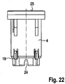
- Fig. 25 is removable - at the according FIGS. 22 to 24 upper end face 25, a first mark 26 is arranged in the form of an outwardly directed arrow.
- This first marking 26 points in a direction perpendicular to the connecting plane between the latching recesses 22, in which also the axis of rotation D and the hinge axis S or longitudinal axis T are offset from each other.
- the current adjustment position can be recognized by a user with the aid of the first marking 26.
- a second mark 27 is provided in the form of two recesses on the support side 9 of the lifting spindle 6.
- the two recesses are arranged opposite to the two locking projections 23, so that they characterize their position and thus the lifting spindle can be brought to place in their function as a rotary tool in the required position for latching.
Landscapes
- Engineering & Computer Science (AREA)
- Mechanical Engineering (AREA)
- Hinges (AREA)
- Pivots And Pivotal Connections (AREA)
- Mutual Connection Of Rods And Tubes (AREA)
- Forms Removed On Construction Sites Or Auxiliary Members Thereof (AREA)
Claims (15)
- Patte de penture (100) d'une penture destinée à la liaison par une articulation à charnière d'un battant sur un cadre autour d'un axe de charnière (S),
dotée d'un évidement longitudinal (3),
dotée d'un coussinet (4), disposé dans l'évidement longitudinal (3), pouvant être mis en rotation autour d'un axe de rotation (D) parallèle à l'axe de charnière (S) et décalé latéralement au moyen d'un outil de rotation, qui comprend un évidement de coussinet (5) destiné à la réception d'un boulon de penture,
dotée d'un filetage intérieur (7) prévu au moins dans la zone inférieure de l'évidement longitudinal (3) dans la position de fonctionnement,
et dotée d'une broche de levage (6) présentant un filetage extérieur (8), se vissant dans le filetage intérieur (7), qui présente une face d'appui (9) pour l'appui immédiat ou non immédiat du coussinet (4) et/ou du boulon de penture,
caractérisée en ce
qu'une surface pour une clé (13) est prévue sur le coussinet (4) et une surface complémentaire pour une clé (14) est prévue sur la broche de levage (6), pouvant être mise en fonctionnement conjointement avec la surface pour la clé (13), qui est disposée sur le côté de la broche de levage (6) situé en face du côté d'appui de sorte que la broche de levage (6) est conçue comme un moyen auxiliaire de rotation (12) pouvant être activé au choix, et peut être employée dans sa fonction d'outil de rotation par le fait qu'elle se dévisse d'abord totalement de l'évidement longitudinal et, inversement est activée avec la face d'appui (9) au niveau du coussinet (4) en pointant au loin par rapport au coussinet (4) e/ou au boulon de bande. - Patte de penture selon la revendication 1, caractérisée en ce que l'évidement de coussinet (5) présente un axe longitudinal (T) qui est disposé décalé latéralement par rapport à l'axe de rotation (D).
- Patte de penture selon la revendication 1 ou 2, caractérisée en ce que l'évidement longitudinal (3) présente au moins une cavité d'encliquetage (17) et qu'au moins une saillie d'encliquetage (18) est prévue sur le coussinet (4).
- Patte de penture selon la revendication 3, caractérisée en ce que la broche de levage (6) est conçue de sorte que l'au moins une saillie d'encliquetage (18) peut être mise en fonctionnement conjointement avec l'au moins une cavité d'encliquetage (17) et peut être en butée lorsque le coussinet (4) et/ou le boulon de penture se situent dans un appui immédiat ou non immédiat au niveau de la face d'appui (9).
- Patte de penture selon la revendication 4, caractérisée en ce que la broche de levage (6) présente un embout (10) de forme annulaire entourant la face d'appui (9) qui se met en prise par l'arrière dans l'au moins une saillie d'encliquetage (18) lorsque le coussinet (4) et/ou le boulon de penture se situent dans un appui immédiat ou non immédiat au niveau de la face d'appui (9).
- Patte de penture selon l'une des revendications 1 à 5, caractérisée en ce qu'au niveau du côté de la broche de levage (6) située en face de la face d'appui (9), il est prévu un rebord (15) de forme annulaire qui se met en prise dans une rainure annulaire (16) prévue sur le coussinet (4) ou formée entre le coussinet (4) et la partie charnière (2) lorsque les surfaces pour la clé et complémentaire pour la clé (13, 14) se trouvent en liaison fonctionnelle.
- Patte de penture selon la revendication 6, caractérisée en ce que le rebord (15) et le coussinet (4) comprennent des moyens pour la transmission de couples de rotation entre le rebord (15) et le coussinet (4).
- Patte de penture selon la revendication 7, caractérisée en ce qu'au niveau du rebord (15), il est prévu au moins une saillie (19) ou au moins une cavité, qui se trouve en liaison fonctionnelle avec au moins une cavité complémentaire (20) ou au moins une saillie complémentaire, ou avec le coussinet (4) lorsque les surface pour la clé et complémentaire pour la clé (13, 14) se trouvent e prise.
- Patte de penture selon l'une des revendications 1 à 8, caractérisée en ce qu'un système de butée (21) est prévu sur le coussinet (4) sur le côté de la surface complémentaire de clé (14) et qu'un système de butée complémentaire (22) est prévu sur le coussinet (4), où, de préférence, le système de butée (21) est une saillie d'encliquetage (23) et le système de butée complémentaire est une cavité d'encliquetage (24) de sorte que la broche de levage (6) peut se placer au choix, moyennant le dépassement d'une force de butée sur le coussinet (4), moyennant une mise en prise des surfaces pour la clé (13) et complémentaire pour la clé (14), ou peut être retirée du coussinet (4) moyennant une séparation des surfaces pour la clé (13) et complémentaire pour la clé (14).
- Patte de penture selon la revendication 9, caractérisée en ce que la saillie d'encliquetage (23) s'étend à partir de la surface complémentaire pour la clé (14) de manière radiale vers l'extérieur.
- Patte de penture selon la revendication 9 ou 10, caractérisée en ce que la cavité complémentaire de butée est prévue dans le pourtour formant la surface pour la clé (13) du coussinet (4).
- Patte de penture selon l'une des revendications 9 à 11, caractérisée en ce que deux systèmes de butée et de butée complémentaire décalés l'un par rapport à l'autre de 180 ° par rapport à l'axe de rotation D sont prévus.
- Patte de penture selon l'une des revendications 9 à 12, caractérisée en ce que les systèmes de butée complémentaire (22) sont disposés dans des relations angulaires déterminées par rapport au décalage latéral de l'axe longitudinal (T) et de l'axe de rotation (D).
- Patte de penture selon la revendication 13, caractérisée en ce que l'orientation du décalage latéral de la face frontale (25) du coussinet (4) s'éloignant de la surface pour la clé (13) est mise en évidence de manière optique par une première marque (26).
- Patte de penture selon la revendication 14, caractérisée en ce qu'au moins une deuxième marque (27) est prévue sur la face d'appui (9) de la broche de levage (6) qui est disposée dans une relation angulaire déterminée par rapport au système de butée (23).
Priority Applications (1)
| Application Number | Priority Date | Filing Date | Title |
|---|---|---|---|
| PL14711503T PL3019683T3 (pl) | 2013-07-12 | 2014-03-19 | Skrzydełko zawiasy |
Applications Claiming Priority (2)
| Application Number | Priority Date | Filing Date | Title |
|---|---|---|---|
| DE202013103109.7U DE202013103109U1 (de) | 2013-07-12 | 2013-07-12 | Bandlappen eines Bandes |
| PCT/EP2014/055464 WO2015003822A1 (fr) | 2013-07-12 | 2014-03-19 | Patte d'une penture |
Publications (2)
| Publication Number | Publication Date |
|---|---|
| EP3019683A1 EP3019683A1 (fr) | 2016-05-18 |
| EP3019683B1 true EP3019683B1 (fr) | 2018-12-12 |
Family
ID=50342314
Family Applications (1)
| Application Number | Title | Priority Date | Filing Date |
|---|---|---|---|
| EP14711503.4A Active EP3019683B1 (fr) | 2013-07-12 | 2014-03-19 | Patte d'une penture |
Country Status (7)
| Country | Link |
|---|---|
| EP (1) | EP3019683B1 (fr) |
| CN (1) | CN105452585B (fr) |
| DE (1) | DE202013103109U1 (fr) |
| PL (1) | PL3019683T3 (fr) |
| RU (1) | RU2638626C2 (fr) |
| TR (1) | TR201900139T4 (fr) |
| WO (1) | WO2015003822A1 (fr) |
Families Citing this family (3)
| Publication number | Priority date | Publication date | Assignee | Title |
|---|---|---|---|---|
| DE102018100774B3 (de) * | 2018-01-15 | 2018-09-27 | Dr. Hahn Gmbh & Co. Kg | Bandlappen eines Bandes |
| DE102020109532B3 (de) * | 2020-04-06 | 2021-02-11 | Dr. Hahn Gmbh & Co. Kg | Band zur um eine Scharnierachse scharniergelenkigen Verbindung |
| GR1011033B (el) * | 2024-11-19 | 2025-09-05 | Κλειθροποιια Domus Ανωνυμος Εμπορικη Και Βιομηχανικη Εταιρια Με Δ.Τ. "Domus Α.Ε.Β.Ε.", | Ρυθμιζομενος μεντεσες για πορτες και παραθυρα |
Family Cites Families (13)
| Publication number | Priority date | Publication date | Assignee | Title |
|---|---|---|---|---|
| US3999246A (en) * | 1974-09-24 | 1976-12-28 | The Stanley Works | Two knuckle hinges |
| DE29703324U1 (de) * | 1997-02-25 | 1998-07-02 | Dr. Hahn GmbH & Co KG, 41189 Mönchengladbach | Band für Türen, Fenster u.dgl. |
| IT1308737B1 (it) * | 1999-06-16 | 2002-01-10 | Savio Spa | Cerniera per serramenti apribili |
| EP1455042B1 (fr) * | 2003-02-21 | 2007-07-25 | Master S.R.L. | Charnière réglable pour fenêtre ou porte |
| DE202004011539U1 (de) * | 2004-07-22 | 2005-12-08 | Dr. Hahn Gmbh & Co. Kg | Band für Türen, Fenster u.dgl. |
| EP2025845B1 (fr) * | 2007-08-09 | 2009-10-07 | ROTO FRANK Aktiengesellschaft | Ferrure de charnière d'une fenêtre, d'une porte ou analogue dotée d'une goupille oblique |
| CN201170011Y (zh) * | 2007-11-22 | 2008-12-24 | 李英学 | 松紧式合页 |
| DE202008014318U1 (de) * | 2008-10-28 | 2010-04-01 | Dr. Hahn Gmbh & Co. Kg | Band zur um eine Scharnierachse scharniergelenkigen Verbindung eines Flügels an einem Rahmen |
| PT2194218E (pt) * | 2008-12-05 | 2011-10-27 | Savio Spa | Dobradiça para portas, janelas ou afins |
| IT1396871B1 (it) * | 2009-12-24 | 2012-12-20 | Gsg Int Spa | Cerniera per infissi pesanti. |
| PL65336Y1 (pl) * | 2009-12-28 | 2011-03-31 | Wala Społka Z Ograniczoną Odpowiedzialnością | Zawias, zwłaszcza do drzwi |
| WO2012045659A1 (fr) * | 2010-10-04 | 2012-04-12 | Dr. Hahn Gmbh & Co. Kg | Procédé et dispositif de transmission de signaux entre un mur et un vantail fixé à ce mur par une charnière tournant autour d'un axe |
| DE202011052372U1 (de) * | 2011-12-20 | 2013-03-21 | Dr. Hahn Gmbh & Co. Kg | Band zur schwenkbaren Verbindung eines Flügels mit einem Rahmen |
-
2013
- 2013-07-12 DE DE202013103109.7U patent/DE202013103109U1/de not_active Expired - Lifetime
-
2014
- 2014-03-19 TR TR2019/00139T patent/TR201900139T4/tr unknown
- 2014-03-19 WO PCT/EP2014/055464 patent/WO2015003822A1/fr not_active Ceased
- 2014-03-19 PL PL14711503T patent/PL3019683T3/pl unknown
- 2014-03-19 EP EP14711503.4A patent/EP3019683B1/fr active Active
- 2014-03-19 RU RU2016103922A patent/RU2638626C2/ru active
- 2014-03-19 CN CN201480039667.0A patent/CN105452585B/zh active Active
Non-Patent Citations (1)
| Title |
|---|
| None * |
Also Published As
| Publication number | Publication date |
|---|---|
| EP3019683A1 (fr) | 2016-05-18 |
| DE202013103109U1 (de) | 2014-10-13 |
| CN105452585B (zh) | 2017-05-10 |
| TR201900139T4 (tr) | 2019-02-21 |
| RU2638626C2 (ru) | 2017-12-14 |
| RU2016103922A (ru) | 2017-08-17 |
| CN105452585A (zh) | 2016-03-30 |
| PL3019683T3 (pl) | 2019-07-31 |
| WO2015003822A1 (fr) | 2015-01-15 |
Similar Documents
| Publication | Publication Date | Title |
|---|---|---|
| EP2318723B1 (fr) | Agencement de fixation avec compensation des tolerances | |
| EP1961976B1 (fr) | Dispositif de fixation | |
| EP3384167B1 (fr) | Douille d'écartement réglable | |
| EP3209888B1 (fr) | Dispositif de fixation rapide, procédé d'assemblage de deux éléments au moyen du dispositif de fixation rapide, et procédé de fabrication afférent | |
| DE60133441T2 (de) | Befestigungsmittel mit Gewinde | |
| EP2063136B1 (fr) | Elément de fixation comprenant une douille imperdable attachable | |
| EP1153186B1 (fr) | Raccord permettant de connecter deux parois minces | |
| DE19647742A1 (de) | Einrichtungs-Anziehvorrichtung für unverlierbare Schrauben | |
| EP3612740B1 (fr) | Unité de réglage et procédé de réglage d'un composant | |
| DE102007039208A1 (de) | Doppelrolle mit zwei Laufrädern sowie Rolle mit einem Laufrad | |
| DE202013101235U1 (de) | Drehmomentschlüssel | |
| EP0362883A1 (fr) | Charnière de malle | |
| EP1219391A2 (fr) | Accouplement a sécurite antisurcharge | |
| WO2013020815A1 (fr) | Système de fixation pour fixer une pièce sur une rainure d'une fenêtre, d'une porte ou analogue | |
| EP1527660B1 (fr) | Dispositif de protection contre la torsion, en particulier pour un boitier de transducteur de mesure | |
| EP3019683B1 (fr) | Patte d'une penture | |
| EP2209959B1 (fr) | Fermeture à compression | |
| EP3425155B1 (fr) | Dispositif de protection anti-pince doigt pour une porte | |
| DE102012020909B3 (de) | Anordnung zur Drehmomentverstellung für einen Schraubendreher | |
| EP2565351B1 (fr) | Agencement de poignée | |
| DE19803372C2 (de) | Vorrichtung und Verfahren für die Montage von Verriegelungseinrichtungen | |
| EP0939186A1 (fr) | Charnière pour portes, fenêtres et similaires. | |
| DE4228946C2 (de) | Spindelkopf für Werkzeugrevolver | |
| EP0467122A1 (fr) | Douille pour broches de ferrures ou charnières | |
| DE102014014086A1 (de) | Schraube und Schraubenanordnung |
Legal Events
| Date | Code | Title | Description |
|---|---|---|---|
| PUAI | Public reference made under article 153(3) epc to a published international application that has entered the european phase |
Free format text: ORIGINAL CODE: 0009012 |
|
| 17P | Request for examination filed |
Effective date: 20160212 |
|
| AK | Designated contracting states |
Kind code of ref document: A1 Designated state(s): AL AT BE BG CH CY CZ DE DK EE ES FI FR GB GR HR HU IE IS IT LI LT LU LV MC MK MT NL NO PL PT RO RS SE SI SK SM TR |
|
| AX | Request for extension of the european patent |
Extension state: BA ME |
|
| DAX | Request for extension of the european patent (deleted) | ||
| GRAJ | Information related to disapproval of communication of intention to grant by the applicant or resumption of examination proceedings by the epo deleted |
Free format text: ORIGINAL CODE: EPIDOSDIGR1 |
|
| STAA | Information on the status of an ep patent application or granted ep patent |
Free format text: STATUS: GRANT OF PATENT IS INTENDED |
|
| GRAP | Despatch of communication of intention to grant a patent |
Free format text: ORIGINAL CODE: EPIDOSNIGR1 |
|
| INTG | Intention to grant announced |
Effective date: 20180905 |
|
| GRAS | Grant fee paid |
Free format text: ORIGINAL CODE: EPIDOSNIGR3 |
|
| GRAA | (expected) grant |
Free format text: ORIGINAL CODE: 0009210 |
|
| STAA | Information on the status of an ep patent application or granted ep patent |
Free format text: STATUS: THE PATENT HAS BEEN GRANTED |
|
| AK | Designated contracting states |
Kind code of ref document: B1 Designated state(s): AL AT BE BG CH CY CZ DE DK EE ES FI FR GB GR HR HU IE IS IT LI LT LU LV MC MK MT NL NO PL PT RO RS SE SI SK SM TR |
|
| REG | Reference to a national code |
Ref country code: GB Ref legal event code: FG4D Free format text: NOT ENGLISH |
|
| REG | Reference to a national code |
Ref country code: CH Ref legal event code: EP |
|
| REG | Reference to a national code |
Ref country code: AT Ref legal event code: REF Ref document number: 1076192 Country of ref document: AT Kind code of ref document: T Effective date: 20181215 |
|
| REG | Reference to a national code |
Ref country code: DE Ref legal event code: R096 Ref document number: 502014010314 Country of ref document: DE |
|
| REG | Reference to a national code |
Ref country code: IE Ref legal event code: FG4D Free format text: LANGUAGE OF EP DOCUMENT: GERMAN |
|
| REG | Reference to a national code |
Ref country code: SE Ref legal event code: TRGR |
|
| REG | Reference to a national code |
Ref country code: NL Ref legal event code: FP |
|
| REG | Reference to a national code |
Ref country code: LT Ref legal event code: MG4D |
|
| PG25 | Lapsed in a contracting state [announced via postgrant information from national office to epo] |
Ref country code: FI Free format text: LAPSE BECAUSE OF FAILURE TO SUBMIT A TRANSLATION OF THE DESCRIPTION OR TO PAY THE FEE WITHIN THE PRESCRIBED TIME-LIMIT Effective date: 20181212 Ref country code: BG Free format text: LAPSE BECAUSE OF FAILURE TO SUBMIT A TRANSLATION OF THE DESCRIPTION OR TO PAY THE FEE WITHIN THE PRESCRIBED TIME-LIMIT Effective date: 20190312 Ref country code: LT Free format text: LAPSE BECAUSE OF FAILURE TO SUBMIT A TRANSLATION OF THE DESCRIPTION OR TO PAY THE FEE WITHIN THE PRESCRIBED TIME-LIMIT Effective date: 20181212 Ref country code: NO Free format text: LAPSE BECAUSE OF FAILURE TO SUBMIT A TRANSLATION OF THE DESCRIPTION OR TO PAY THE FEE WITHIN THE PRESCRIBED TIME-LIMIT Effective date: 20190312 Ref country code: ES Free format text: LAPSE BECAUSE OF FAILURE TO SUBMIT A TRANSLATION OF THE DESCRIPTION OR TO PAY THE FEE WITHIN THE PRESCRIBED TIME-LIMIT Effective date: 20181212 Ref country code: HR Free format text: LAPSE BECAUSE OF FAILURE TO SUBMIT A TRANSLATION OF THE DESCRIPTION OR TO PAY THE FEE WITHIN THE PRESCRIBED TIME-LIMIT Effective date: 20181212 Ref country code: LV Free format text: LAPSE BECAUSE OF FAILURE TO SUBMIT A TRANSLATION OF THE DESCRIPTION OR TO PAY THE FEE WITHIN THE PRESCRIBED TIME-LIMIT Effective date: 20181212 |
|
| PG25 | Lapsed in a contracting state [announced via postgrant information from national office to epo] |
Ref country code: AL Free format text: LAPSE BECAUSE OF FAILURE TO SUBMIT A TRANSLATION OF THE DESCRIPTION OR TO PAY THE FEE WITHIN THE PRESCRIBED TIME-LIMIT Effective date: 20181212 Ref country code: RS Free format text: LAPSE BECAUSE OF FAILURE TO SUBMIT A TRANSLATION OF THE DESCRIPTION OR TO PAY THE FEE WITHIN THE PRESCRIBED TIME-LIMIT Effective date: 20181212 Ref country code: GR Free format text: LAPSE BECAUSE OF FAILURE TO SUBMIT A TRANSLATION OF THE DESCRIPTION OR TO PAY THE FEE WITHIN THE PRESCRIBED TIME-LIMIT Effective date: 20190313 |
|
| PG25 | Lapsed in a contracting state [announced via postgrant information from national office to epo] |
Ref country code: PT Free format text: LAPSE BECAUSE OF FAILURE TO SUBMIT A TRANSLATION OF THE DESCRIPTION OR TO PAY THE FEE WITHIN THE PRESCRIBED TIME-LIMIT Effective date: 20190412 |
|
| PG25 | Lapsed in a contracting state [announced via postgrant information from national office to epo] |
Ref country code: EE Free format text: LAPSE BECAUSE OF FAILURE TO SUBMIT A TRANSLATION OF THE DESCRIPTION OR TO PAY THE FEE WITHIN THE PRESCRIBED TIME-LIMIT Effective date: 20181212 Ref country code: SM Free format text: LAPSE BECAUSE OF FAILURE TO SUBMIT A TRANSLATION OF THE DESCRIPTION OR TO PAY THE FEE WITHIN THE PRESCRIBED TIME-LIMIT Effective date: 20181212 Ref country code: IS Free format text: LAPSE BECAUSE OF FAILURE TO SUBMIT A TRANSLATION OF THE DESCRIPTION OR TO PAY THE FEE WITHIN THE PRESCRIBED TIME-LIMIT Effective date: 20190412 Ref country code: RO Free format text: LAPSE BECAUSE OF FAILURE TO SUBMIT A TRANSLATION OF THE DESCRIPTION OR TO PAY THE FEE WITHIN THE PRESCRIBED TIME-LIMIT Effective date: 20181212 Ref country code: SK Free format text: LAPSE BECAUSE OF FAILURE TO SUBMIT A TRANSLATION OF THE DESCRIPTION OR TO PAY THE FEE WITHIN THE PRESCRIBED TIME-LIMIT Effective date: 20181212 |
|
| REG | Reference to a national code |
Ref country code: DE Ref legal event code: R097 Ref document number: 502014010314 Country of ref document: DE |
|
| PLBE | No opposition filed within time limit |
Free format text: ORIGINAL CODE: 0009261 |
|
| STAA | Information on the status of an ep patent application or granted ep patent |
Free format text: STATUS: NO OPPOSITION FILED WITHIN TIME LIMIT |
|
| PG25 | Lapsed in a contracting state [announced via postgrant information from national office to epo] |
Ref country code: DK Free format text: LAPSE BECAUSE OF FAILURE TO SUBMIT A TRANSLATION OF THE DESCRIPTION OR TO PAY THE FEE WITHIN THE PRESCRIBED TIME-LIMIT Effective date: 20181212 Ref country code: SI Free format text: LAPSE BECAUSE OF FAILURE TO SUBMIT A TRANSLATION OF THE DESCRIPTION OR TO PAY THE FEE WITHIN THE PRESCRIBED TIME-LIMIT Effective date: 20181212 Ref country code: MC Free format text: LAPSE BECAUSE OF FAILURE TO SUBMIT A TRANSLATION OF THE DESCRIPTION OR TO PAY THE FEE WITHIN THE PRESCRIBED TIME-LIMIT Effective date: 20181212 |
|
| REG | Reference to a national code |
Ref country code: CH Ref legal event code: PL |
|
| 26N | No opposition filed |
Effective date: 20190913 |
|
| PG25 | Lapsed in a contracting state [announced via postgrant information from national office to epo] |
Ref country code: LU Free format text: LAPSE BECAUSE OF NON-PAYMENT OF DUE FEES Effective date: 20190319 |
|
| PG25 | Lapsed in a contracting state [announced via postgrant information from national office to epo] |
Ref country code: IE Free format text: LAPSE BECAUSE OF NON-PAYMENT OF DUE FEES Effective date: 20190319 Ref country code: LI Free format text: LAPSE BECAUSE OF NON-PAYMENT OF DUE FEES Effective date: 20190331 Ref country code: CH Free format text: LAPSE BECAUSE OF NON-PAYMENT OF DUE FEES Effective date: 20190331 |
|
| PG25 | Lapsed in a contracting state [announced via postgrant information from national office to epo] |
Ref country code: MT Free format text: LAPSE BECAUSE OF FAILURE TO SUBMIT A TRANSLATION OF THE DESCRIPTION OR TO PAY THE FEE WITHIN THE PRESCRIBED TIME-LIMIT Effective date: 20181212 |
|
| PG25 | Lapsed in a contracting state [announced via postgrant information from national office to epo] |
Ref country code: CY Free format text: LAPSE BECAUSE OF FAILURE TO SUBMIT A TRANSLATION OF THE DESCRIPTION OR TO PAY THE FEE WITHIN THE PRESCRIBED TIME-LIMIT Effective date: 20181212 |
|
| PGFP | Annual fee paid to national office [announced via postgrant information from national office to epo] |
Ref country code: GB Payment date: 20210310 Year of fee payment: 8 Ref country code: AT Payment date: 20210225 Year of fee payment: 8 |
|
| PG25 | Lapsed in a contracting state [announced via postgrant information from national office to epo] |
Ref country code: HU Free format text: LAPSE BECAUSE OF FAILURE TO SUBMIT A TRANSLATION OF THE DESCRIPTION OR TO PAY THE FEE WITHIN THE PRESCRIBED TIME-LIMIT; INVALID AB INITIO Effective date: 20140319 |
|
| PG25 | Lapsed in a contracting state [announced via postgrant information from national office to epo] |
Ref country code: MK Free format text: LAPSE BECAUSE OF FAILURE TO SUBMIT A TRANSLATION OF THE DESCRIPTION OR TO PAY THE FEE WITHIN THE PRESCRIBED TIME-LIMIT Effective date: 20181212 |
|
| REG | Reference to a national code |
Ref country code: AT Ref legal event code: MM01 Ref document number: 1076192 Country of ref document: AT Kind code of ref document: T Effective date: 20220319 |
|
| GBPC | Gb: european patent ceased through non-payment of renewal fee |
Effective date: 20220319 |
|
| REG | Reference to a national code |
Ref country code: DE Ref legal event code: R082 Ref document number: 502014010314 Country of ref document: DE Representative=s name: PATENTANWAELTE KLUIN DEBELIUS WEBER PARTG MBB, DE |
|
| PG25 | Lapsed in a contracting state [announced via postgrant information from national office to epo] |
Ref country code: GB Free format text: LAPSE BECAUSE OF NON-PAYMENT OF DUE FEES Effective date: 20220319 Ref country code: AT Free format text: LAPSE BECAUSE OF NON-PAYMENT OF DUE FEES Effective date: 20220319 |
|
| P01 | Opt-out of the competence of the unified patent court (upc) registered |
Effective date: 20230523 |
|
| PGFP | Annual fee paid to national office [announced via postgrant information from national office to epo] |
Ref country code: NL Payment date: 20250324 Year of fee payment: 12 |
|
| PGFP | Annual fee paid to national office [announced via postgrant information from national office to epo] |
Ref country code: CZ Payment date: 20250306 Year of fee payment: 12 Ref country code: PL Payment date: 20250310 Year of fee payment: 12 |
|
| PGFP | Annual fee paid to national office [announced via postgrant information from national office to epo] |
Ref country code: IT Payment date: 20250331 Year of fee payment: 12 |
|
| PGFP | Annual fee paid to national office [announced via postgrant information from national office to epo] |
Ref country code: SE Payment date: 20260323 Year of fee payment: 13 |
|
| PGFP | Annual fee paid to national office [announced via postgrant information from national office to epo] |
Ref country code: DE Payment date: 20260331 Year of fee payment: 13 |
|
| PGFP | Annual fee paid to national office [announced via postgrant information from national office to epo] |
Ref country code: BE Payment date: 20260323 Year of fee payment: 13 |
|
| PGFP | Annual fee paid to national office [announced via postgrant information from national office to epo] |
Ref country code: FR Payment date: 20260324 Year of fee payment: 13 |
|
| PGFP | Annual fee paid to national office [announced via postgrant information from national office to epo] |
Ref country code: TR Payment date: 20260316 Year of fee payment: 13 |