EP3019703B1 - Motorantriebssystem - Google Patents
Motorantriebssystem Download PDFInfo
- Publication number
- EP3019703B1 EP3019703B1 EP14823797.7A EP14823797A EP3019703B1 EP 3019703 B1 EP3019703 B1 EP 3019703B1 EP 14823797 A EP14823797 A EP 14823797A EP 3019703 B1 EP3019703 B1 EP 3019703B1
- Authority
- EP
- European Patent Office
- Prior art keywords
- media
- propulsion system
- firing pin
- cannon
- pressure
- Prior art date
- Legal status (The legal status is an assumption and is not a legal conclusion. Google has not performed a legal analysis and makes no representation as to the accuracy of the status listed.)
- Not-in-force
Links
- 238000010304 firing Methods 0.000 claims description 167
- 230000001360 synchronised effect Effects 0.000 claims description 7
- 230000007423 decrease Effects 0.000 description 4
- 238000000034 method Methods 0.000 description 3
- 208000027418 Wounds and injury Diseases 0.000 description 2
- 230000006378 damage Effects 0.000 description 2
- 208000014674 injury Diseases 0.000 description 2
- 230000001133 acceleration Effects 0.000 description 1
- 230000004913 activation Effects 0.000 description 1
- 238000002485 combustion reaction Methods 0.000 description 1
- 230000006835 compression Effects 0.000 description 1
- 238000007906 compression Methods 0.000 description 1
- 230000001143 conditioned effect Effects 0.000 description 1
- 230000003247 decreasing effect Effects 0.000 description 1
- 238000006073 displacement reaction Methods 0.000 description 1
- 238000004880 explosion Methods 0.000 description 1
- 230000004907 flux Effects 0.000 description 1
- 238000002347 injection Methods 0.000 description 1
- 239000007924 injection Substances 0.000 description 1
- 230000003068 static effect Effects 0.000 description 1
- XLYOFNOQVPJJNP-UHFFFAOYSA-N water Substances O XLYOFNOQVPJJNP-UHFFFAOYSA-N 0.000 description 1
Images







Classifications
-
- F—MECHANICAL ENGINEERING; LIGHTING; HEATING; WEAPONS; BLASTING
- F02—COMBUSTION ENGINES; HOT-GAS OR COMBUSTION-PRODUCT ENGINE PLANTS
- F02K—JET-PROPULSION PLANTS
- F02K9/00—Rocket-engine plants, i.e. plants carrying both fuel and oxidant therefor; Control thereof
- F02K9/95—Rocket-engine plants, i.e. plants carrying both fuel and oxidant therefor; Control thereof characterised by starting or ignition means or arrangements
-
- F—MECHANICAL ENGINEERING; LIGHTING; HEATING; WEAPONS; BLASTING
- F02—COMBUSTION ENGINES; HOT-GAS OR COMBUSTION-PRODUCT ENGINE PLANTS
- F02C—GAS-TURBINE PLANTS; AIR INTAKES FOR JET-PROPULSION PLANTS; CONTROLLING FUEL SUPPLY IN AIR-BREATHING JET-PROPULSION PLANTS
- F02C3/00—Gas-turbine plants characterised by the use of combustion products as the working fluid
- F02C3/14—Gas-turbine plants characterised by the use of combustion products as the working fluid characterised by the arrangement of the combustion chamber in the plant
-
- F—MECHANICAL ENGINEERING; LIGHTING; HEATING; WEAPONS; BLASTING
- F02—COMBUSTION ENGINES; HOT-GAS OR COMBUSTION-PRODUCT ENGINE PLANTS
- F02C—GAS-TURBINE PLANTS; AIR INTAKES FOR JET-PROPULSION PLANTS; CONTROLLING FUEL SUPPLY IN AIR-BREATHING JET-PROPULSION PLANTS
- F02C3/00—Gas-turbine plants characterised by the use of combustion products as the working fluid
- F02C3/14—Gas-turbine plants characterised by the use of combustion products as the working fluid characterised by the arrangement of the combustion chamber in the plant
- F02C3/16—Gas-turbine plants characterised by the use of combustion products as the working fluid characterised by the arrangement of the combustion chamber in the plant the combustion chambers being formed at least partly in the turbine rotor or in an other rotating part of the plant
- F02C3/165—Gas-turbine plants characterised by the use of combustion products as the working fluid characterised by the arrangement of the combustion chamber in the plant the combustion chambers being formed at least partly in the turbine rotor or in an other rotating part of the plant the combustion chamber contributes to the driving force by creating reactive thrust
-
- F—MECHANICAL ENGINEERING; LIGHTING; HEATING; WEAPONS; BLASTING
- F02—COMBUSTION ENGINES; HOT-GAS OR COMBUSTION-PRODUCT ENGINE PLANTS
- F02C—GAS-TURBINE PLANTS; AIR INTAKES FOR JET-PROPULSION PLANTS; CONTROLLING FUEL SUPPLY IN AIR-BREATHING JET-PROPULSION PLANTS
- F02C5/00—Gas-turbine plants characterised by the working fluid being generated by intermittent combustion
- F02C5/02—Gas-turbine plants characterised by the working fluid being generated by intermittent combustion characterised by the arrangement of the combustion chamber in the chamber in the plant
-
- F—MECHANICAL ENGINEERING; LIGHTING; HEATING; WEAPONS; BLASTING
- F02—COMBUSTION ENGINES; HOT-GAS OR COMBUSTION-PRODUCT ENGINE PLANTS
- F02C—GAS-TURBINE PLANTS; AIR INTAKES FOR JET-PROPULSION PLANTS; CONTROLLING FUEL SUPPLY IN AIR-BREATHING JET-PROPULSION PLANTS
- F02C5/00—Gas-turbine plants characterised by the working fluid being generated by intermittent combustion
- F02C5/02—Gas-turbine plants characterised by the working fluid being generated by intermittent combustion characterised by the arrangement of the combustion chamber in the chamber in the plant
- F02C5/04—Gas-turbine plants characterised by the working fluid being generated by intermittent combustion characterised by the arrangement of the combustion chamber in the chamber in the plant the combustion chambers being formed at least partly in the turbine rotor
-
- F—MECHANICAL ENGINEERING; LIGHTING; HEATING; WEAPONS; BLASTING
- F02—COMBUSTION ENGINES; HOT-GAS OR COMBUSTION-PRODUCT ENGINE PLANTS
- F02C—GAS-TURBINE PLANTS; AIR INTAKES FOR JET-PROPULSION PLANTS; CONTROLLING FUEL SUPPLY IN AIR-BREATHING JET-PROPULSION PLANTS
- F02C5/00—Gas-turbine plants characterised by the working fluid being generated by intermittent combustion
- F02C5/12—Gas-turbine plants characterised by the working fluid being generated by intermittent combustion the combustion chambers having inlet or outlet valves, e.g. Holzwarth gas-turbine plants
-
- F—MECHANICAL ENGINEERING; LIGHTING; HEATING; WEAPONS; BLASTING
- F02—COMBUSTION ENGINES; HOT-GAS OR COMBUSTION-PRODUCT ENGINE PLANTS
- F02K—JET-PROPULSION PLANTS
- F02K9/00—Rocket-engine plants, i.e. plants carrying both fuel and oxidant therefor; Control thereof
-
- F—MECHANICAL ENGINEERING; LIGHTING; HEATING; WEAPONS; BLASTING
- F41—WEAPONS
- F41A—FUNCTIONAL FEATURES OR DETAILS COMMON TO BOTH SMALLARMS AND ORDNANCE, e.g. CANNONS; MOUNTINGS FOR SMALLARMS OR ORDNANCE
- F41A19/00—Firing or trigger mechanisms; Cocking mechanisms
- F41A19/06—Mechanical firing mechanisms, e.g. counterrecoil firing, recoil actuated firing mechanisms
- F41A19/13—Percussion or firing pins, i.e. fixed or slidably-mounted striker elements; Mountings therefor
-
- H—ELECTRICITY
- H02—GENERATION; CONVERSION OR DISTRIBUTION OF ELECTRIC POWER
- H02K—DYNAMO-ELECTRIC MACHINES
- H02K7/00—Arrangements for handling mechanical energy structurally associated with dynamo-electric machines, e.g. structural association with mechanical driving motors or auxiliary dynamo-electric machines
- H02K7/18—Structural association of electric generators with mechanical driving motors, e.g. with turbines
- H02K7/1807—Rotary generators
- H02K7/1823—Rotary generators structurally associated with turbines or similar engines
-
- F—MECHANICAL ENGINEERING; LIGHTING; HEATING; WEAPONS; BLASTING
- F05—INDEXING SCHEMES RELATING TO ENGINES OR PUMPS IN VARIOUS SUBCLASSES OF CLASSES F01-F04
- F05D—INDEXING SCHEME FOR ASPECTS RELATING TO NON-POSITIVE-DISPLACEMENT MACHINES OR ENGINES, GAS-TURBINES OR JET-PROPULSION PLANTS
- F05D2220/00—Application
- F05D2220/30—Application in turbines
- F05D2220/32—Application in turbines in gas turbines
Definitions
- the embodiments herein relate generally to mechanical actuators that convert hydraulic pressure and flow into torque and angular displacement.
- Embodiments of the present invention propose more efficient mechanical actuators by using fewer hinges and connections, thus more energy turns the shaft.
- Other embodiments of the disclosed invention provide for precision air injection for combustion engines and bursts of air for removing debris or water from windshields.
- Document RS 20 110 375 A1 discloses an engine propulsion system.
- an engine propulsion system is configured to utilize bursts of media in order to create mechanical energy.
- the engine propulsion system includes at least one cannon, wherein each cannon is configured to displace the media and further includes a firing pin casing configured to accommodate a firing pin.
- the firing pin is configured to create the mechanical energy when moved thus allowing the media to exit the cannon.
- the firing pin comprises a channel and mechanically coupled to a second pressure regulator and a first pressure regulator.
- the second pressure regulator is configured to permit second pressure media to enter the firing pin.
- the first pressure regulator is configured to pass through a solenoid to permit first pressure media, to enter a first pressure cannon port to charge and a first pressure port to fire.
- a firing pin obstruction cylinder is located in the channel and arranged to obstruct movement of the second pressure media in the channel.
- a hat is mechanically coupled to the firing pin and immediately adjacent to the firing pin obstruction cylinder which permits the second pressure media to move past the firing pin obstruction cylinder through the channel once the first pressure media has pushed the firing pin obstruction cylinder past the hat.
- the second pressure media is configured to create the mechanical energy configured to be used in the engine propulsion system.
- the at least one cannon can proximate a media propulsion system.
- the media propulsion system can further comprise a reservoir which contains the media.
- the media propulsion system can further comprise a pump configured to pump the media.
- the media propulsion system can further comprise at least one pressure intensifier to condition the media for pressurization.
- the media propulsion system can further comprise at least one check valve.
- the media propulsion system can further comprise at least one accumulator attached to a regulator and is configured to accumulate the media.
- the media propulsion system can further comprise at least one solenoid attached to the firing pin casing and configured to disperse the media.
- the media propulsion system can further comprise a tube seal proximate a tube media exit wherein a second pressure media is discharged through the tube media exit causing propulsion.
- the media propulsion system can further comprise seals configured to isolate the media from all channels and configured to prevent the media from inadvertently escaping a controlled exit from the engine propulsion system.
- the at least one cannon can have one exit port. In other embodiments, the at least one cannon can be a plurality of cannons and the plurality of cannons can share an exit port.
- the at least one cannon can be configured to operate in a synchronized mode of operation.
- the synchronized mode of operation can use at least one motor.
- the at least one cannon can be configured to operate in an alternating mode of operation.
- the alternating mode of operation can use at least one motor.
- the engine propulsion system can further include an axel mechanically coupled to the at least one cannon.
- the at least one cannon can create the mechanical energy by turning the axel.
- a surface can be sealed and covered in order to prevent injury which otherwise could be caused by exposure to the surface.
- An engine propulsion system further comprises turbine blades that can be mechanically coupled to at least one cannon.
- a turbine shaft can be mechanically coupled to the turbine blades configured such that the at least one cannon creates mechanical energy by turning the turbine shaft.
- an electronic propulsion nozzle arranged proximate turbine blades and configured to allow space flight.
- An energy generation tubing or channel can be configured to charge a battery.
- the energy generation tubing comprises a plurality of turbine shafts each mechanically coupled to a plurality of turbine blades. At least one generator can be attached to each turbine shaft forming a series of turbine/generator systems. A medium surrounding and passing the series of turbine/generator systems can create electrical power.
- An energy generation tubing or channel can be configured to charge a battery.
- the energy generation tubing comprises a plurality of turbine shafts each mechanically coupled to a plurality of turbine blades. At least one generator can be attached to each turbine shaft forming a series of turbine/alternator systems. A medium surrounding and passing the series of turbine/generator systems can create electrical power.
- a cannon can be configured to displace media.
- the cannon can include a firing pin is a rotational firing pin having a rotational firing pin stern.
- a firing pin obstruction cylinder can be a rotational firing pin obstruction cylinder which can be mechanically coupled to the rotational firing pin stern with a rotational firing pin stem.
- At least one rotational firing pin charge shaft can be embedded with the rotational firing pin stern and configured to be immediately adjacent to a channel.
- At least one rotational firing pin firing shaft can be embedded within the rotational firing pin obstruction cylinder.
- a turn shaft can be mechanically coupled to the rotational firing pin stern.
- a second pressure media can be configured to charge and release from at least one rotational firing pin charging and firing ports creating a mechanical energy.
- the cannon can further comprise a hat mechanically coupled to the firing pin and immediately adjacent to the firing pin obstruction cylinder which permits pressurized media to move past the firing pin obstruction cylinder through the channel once the pressurized media has pushed the firing pin obstruction cylinder past the hat.
- the pressurized media can be configured to create the mechanical energy.
- a cannon can be configured to displace media.
- the cannon can comprise a firing pin casing configured to accommodate a firing pin.
- the firing pin can comprise a channel and mechanically coupled to a second pressure regulator and a first pressure regulator.
- the second pressure regulator can be configured to permit second pressure media to enter the firing pin.
- the first pressure regulator can be configured to permit first pressure media to travel through a solenoid configured to direct firing or charging of the cannon.
- the second pressure regulator and the first pressure regulator can be further mechanically coupled to a media propulsion system.
- a firing pin obstruction cylinder can be located in the channel and arranged to obstruct movement of the second pressure media in the channel.
- the second pressure media can be configured to create mechanical energy.
- the at least one cannon can be configured to operate in a synchronized mode of operation.
- the synchronized mode of operation can use at least one motor.
- the at least one cannon can have at least one exit port.
- the at least one cannon can be a plurality of cannons and the plurality of cannons share an exit port.
- the at least one cannon can be configured to operate in an alternating mode of operation.
- the alternating mode of operation can use at least one motor.
- the at least one cannon can have at least one exit port.
- the at least one cannon can be a plurality of cannons and the plurality of cannons share an exit port.
- An electronic system can be configured to operate an engine propulsion system to create mechanical energy.
- the electronic system can include a central processing unit mechanically coupled to the engine propulsion system and configured to engage the engine propulsion system.
- the central processing unit can further communicate with a local processing unit communicatively coupled to solenoids which directs the engine propulsion system.
- the central processing unit can further comprise processor instructions for accelerating the engine propulsion system, further comprising: calculating stored energy available.
- the central processing unit can further comprises processor instructions for accelerating the engine propulsion system, further comprising: determining additional energy and/or firing rate needed to accelerate.
- the central processing unit can further comprise processor instructions for accelerating the engine propulsion system, further comprising: increasing pressure and/or firing rate of a media thereby obtaining additional energy.
- the central processing unit further can further comprises processor instructions for accelerating the engine propulsion system, further comprise: increasing a cannon firing rate.
- the central processing unit further can further comprise processor instructions for accelerating the engine propulsion system, further comprising: calculating and displaying a time until stored energy and/or media is depleted.
- the central processing unit can further comprises processor instructions for decelerating the engine propulsion system, further comprising: reducing a cannon firing rate.
- the central processing unit can further comprise processor instructions for decelerating the engine propulsion system, further comprising: decreasing energy being emitted on the engine propulsion system.
- the central processing unit can further comprise processor instructions for decelerating the engine propulsion system, further comprising: calculating and displaying a time until stored energy is restored.
- the central processing unit can further comprise processor instructions for decelerating the engine propulsion system, further comprising: displaying an error if an operating rate is less than or equal to a rate to increase stored energy; but only if a first stored energy value at a first time is equal to a second stored energy value at a second time.
- a local processing unit can be communicatively coupled to each solenoid wherein at least one solenoid is mechanically coupled to at least one cannon. The local processing unit can directs the at least one solenoid as to when to fire each connected cannon.
- a process for creating mechanical energy on a rotating device contains the following steps which are not necessarily in order: First, attaching a propulsion device to the rotating device. Next, surrounding the propulsion device with a media. Then, pushing the media from the propulsion device creating a force. The force moves the rotating device creating the mechanical energy.
- directing flow of the media through a cannon with at least one solenoid following that, directing flow of the media through a cannon with at least one solenoid. In some embodiments, after that, isolating media from all channels with seals and preventing the media from inadvertently escaping a controlled exit from the rotating device.
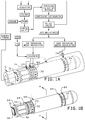
- one embodiment of the engine propulsion system comprises cannon 10 which is a housing for firing pin 12.
- Firing pin 12 comprises firing pin outer casing 11 which is mechanically coupled to cannon 10 such that second pressure media input 74 can insert second pressure media into second pressure cannon port entrance 34.
- firing pin outer casing 11 is mechanically coupled to cannon 10 such that first pressure media input 63 can insert first pressure media into first pressure cannon port entrance 32 and first pressure port to charge channel 54 can insert first pressure media into first pressure port to charge 56.
- First pressure media and second pressure media are simply terms used to show that these two pressures are different. Either could be greater than the other and the system would still function.
- Firing pin 12 receives and then ejects second pressure media in order to create mechanical energy.
- the media is first collected in the reservoir from the energy tubing that houses a plurality of turbines, which when turned from the flow of media, which charges the system's battery.
- the media is pumped through a filter with a pump powered by a separate engine and is then conditioned for pressurization and safety by pushing the media through filters, a check valve, a pressure intensifier and safety relief valve, which the whole system can also include at least one double block and bleed valve or a plurality of double block and bleed valves.
- there is at least one check valve but in other embodiments there can be a plurality of check valves.
- the media is then stored for compression in the system's accumulators.
- there is at least one accumulator but in other embodiments there may be a plurality of accumulators.
- the accumulators which may be of different types such as bladder, piston, gas, etc.
- Firing pin 12 comprises firing pin stern 16 mechanically coupled to first firing pin stern seal 22 and second firing pin stern seal 22. Firing pin stern 16 is mechanically coupled to firing pin stem 28. Firing pin stem 28 is further mechanically coupled to firing pin obstruction cylinder 26. Firing pin obstruction cylinder 26 is connected to hat 38. Hat 38 is perforated by firing pin cylinder ports for second pressure media 44. Hat 38 is mechanically coupled to firing pin sail bumper 20 with firing pin sail seal 14. Firing pin sail bumper 20 is attached to firing pin tube 18 which is hollow and comprises a channel. Firing pin tube 18 is mechanically coupled to tube seal 58 proximate tube media exit 42.
- the seals operate to ensure that the media makes a controlled exit from the cannon at an exit port.
- a controlled exist is one that is parallel to the direction of intended force, and uncontrolled exit, or explosion, occurs when media is dispersed randomly in a direction other than that parallel to desired force.
- Firing pin stern 16 takes the shape of a modified cube, or cylinder, which can move slight lightly within firing pin outer casing 11 toward and away from end cap 24 which is mechanically coupled to firing pin outer casing 12. Firing in outer casing 12 is perforated with second pressure cannon port entrance 34 which permits second pressure media to enter firing pin 12 as indicated above. However, each side of firing pin outer casing 11 proximate second pressure cannon port entrance 34 is mechanically coupled to outer seal 64 to keep the second pressure media from otherwise entering firing pin 12.
- Firing pin outer casing 11 is perforated with first pressure port to fire 32 which can allow first pressure media to enter the channel.
- First pressure port to fire 32 is surrounded by main shaft seal 30 and outer seal 64 to ensure that first pressure media is directed into the channel and not elsewhere.
- a second first pressure inlet is designed to charge the system as shown in more detail in Figure 5 .
- Firing pin outer casing 11 is perforated with first pressure port to charge channel 56 which can allow first pressure media to enter the channel.
- First pressure port to charge channel 56 is surrounded by main shaft seal 30 and outer seal 64 to ensure that first pressure media is directed into the channel and not elsewhere.
- Figure 5 show the firing pin firing sequence.
- the CPU sends a signal to allow the solenoid to activate the first pressure media through first pressure port to charge channel 56 enabling media transfer to push firing pin stern 16 proximate end cap 24.
- the firing pin is charged. Firing pin 12 cannot be prematurely discharged because hat 38 is surrounded by hat seal 40 which prevents movement of media.
- the CPU sends a signal to allow the solenoid to activate the transfer of first pressure media through first pressure cannon port entrance 32. This pushes firing pin obstruction cylinder away from end cap 24. This allows a greater amount of pressurized media to pressurize the firing pin causing the firing pin to fire. Finally, the second pressure media pushes firing pin obstruction cylinder 26 past hat 38 allowing second pressure media to discharge through tube media exit 42.
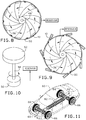
- FIG. 8 Figure 8 and Figure 10 offer one embodiment of how to user cannon 10.
- Cannon 10 is mechanically coupled to turbine blades 36 which turn turbine shaft 48 inside of a sealed turbine enclosure 50.
- Turbine shaft 48 could be used to turn turbine/generator systems 52 or a series of turbine/alternator systems as shown in Figure 10 or for any other purpose.
- Turbine shaft 48 is an example of an axel that is used in a turbine, but other kinds of axels can be used as well.
- An electronic propulsion system or electronic system is mechanically coupled to the energy propulsion system configured to determine when each cannon 10 is configured to fire and then reload.
- a surface such as turbine blades 36 is mechanically coupled to each cannon wherein each cannon firing moves the surface.
- the surface is sealed and covered in order to prevent injury which otherwise could be caused by exposure to the surface.
- the surface is utilized to create mechanical energy.
- the process has the following steps which are not necessarily in order: first, directing a propulsion device towards the rotating device.
- the propulsion device can be cannon 10 and the rotating device can be the turbine with turbine blades 36 attached to turbine shaft 48.
- the turbine can be attached to a generator/alternator.
- there is at least one alternator but in other embodiments there may be a plurality of alternators.
- there is at least one generator but in other embodiments there may be a plurality of generators.
- there is at least one motor but in other embodiments there may be a plurality of motors.
- the turbine can be attached to cannon 10. In some embodiments there is at least one cannon 10, but in other embodiments there may be a plurality of cannons 10. In some embodiments, the plurality of cannons can share at least one exit port.
- Figure 11 shows another use in automobile 60.
- many turbines can be used to turn shaft 62 and thus wheels 66 either individually or in concert as determined by the CPU.
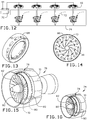
- Figure 12 shows another embodiment containing an energy generation tubing designed to charge battery 70.
- Second pressure media input 74 surrounds medium 72 which turns a series of turbine/generator systems 52 which in turn charge battery 70 with electrical power.
- a generator means a device that generates power, whether it be by alternating current or direct current
- FIG 13 and Figure 14 show an alternate embodiment involving wheel 66.
- Each wheel contains a media that covers turbine blades 36 mechanically such that each wheel can spin on its own without powering a shaft as in Figure 11 .
- the CPU can act as a controller.
- Jet engine 76 comprises medium cavity 78 mechanically coupled to cavity divider 80.
- One side of cavity divider 80 is mechanically coupled to turbine blades 82.
- the other side of cavity divider 80 is mechanically coupled to a plurality of cannons 10.
- Cannons 10 turn cavity divider 80 and thus turbine blades 82 creating propulsion.
- a de Laval Nozzle can be utilized with a gas source to enable spaceflight.
- any electronic propulsion nozzle can be used.
- Rotational firing pin 84 comprises rotational firing pin stern 86 connected to rotational firing pin obstruction cylinder 88 with rotational firing pin stem 90.
- Rotational firing pin stern 86 is further mechanically coupled to turn shaft 102.
- Rotational firing pin stern 86 further comprises at least one firing pin firing shafts 98 each connected to at least one rotational firing pin charge shaft 96 and is sealed with rotational firing pin stern seal 22.
- Rotational firing pin obstruction cylinder 88 further comprises a plurality of rotational firing pin firing shafts 98.
- rotational firing pin 84 is housed in rotational firing pin outer casing 92.
- Rotational firing pin outer casing 92 comprises second pressure cannon port entrance 34.
- Second pressure cannon port entrance 34 is configured to permit media through second pressure input port 94.
- Each side of rotational firing pin outer casing 92 proximate rotational firing pin firing shaft 98 is mechanically coupled to outer seal 64 to keep the second pressure media from otherwise entering rotational firing pin 84.
- each side of rotational firing pin obstruction cylinder 88 proximate rotational firing pin firing shaft 98 is mechanically coupled to hat seal 40 to prevent unwanted discharge of media through a location other than rotational firing pin firing shaft 98. The media is discharged through outer casing firing port 100.
- Figure 23 and 24 further demonstrate the rapid firing sequence of rotational firing pin 84.
- Second pressure media is inserted through second pressure input port 94, and down rotational firing pin charge shaft 96 pressurizing a chamber surrounding some of rotational firing pin obstruction cylinder 88 and rotational firing pin stem 90.
- the pressure second pressure media is discharged through at least one rotational firing pin firing shaft 98 causing rotational firing pin obstruction cylinder 88, rotational firing pin stem 90, rotational firing pin stern 86 and thus turn shaft 102 to rotate creating mechanical energy by turn shaft 102 that can be used for a variety of purposes.
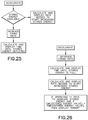
- Figure 25 shows a logic pattern for operating an embodiment of the invention in acceleration mode.
- the CPU calculates the stored energy available and determines the additional energy needed to accelerate. This additional energy can be obtained by faster activation of first pressure media entrance LP1 and first pressure media entrance LP2. As a result the firing pin firing rate or the cannon firing rate will increase.
- the CPU will have access to calculate and display the time until the stored energy is depleted. That is, under the second law of thermodynamics, the pressure in the system will decrease slightly over time due to entropy and require some external pressurization from pumps as noted above.
- Figure 26 shows a logic pattern for operating an embodiment of the invention in deceleration mode. Deceleration involves reducing the firing rate. This involves a bit of the laws of motion as well as a bit of thermodynamics. As the firing rate decreases the firing rate decreases but the energy being done on the system as a whole also decreases. Likewise reinvigorating the system requires some external energy. So, the time until the energy store is full is calculated and displayed by the CPU. Likewise, the rate needed to start increasing the stored energy is also calculated and displayed. If the operating rate is less than or equal to the rate to increase stored energy then if the first stored energy value at a first time is equal to the second stored energy value at a second time then an error is displayed. If not, no error is displayed.
- the rotational firing pins 84 be constantly fired with bursts of second pressure media. This is a synchronized mode of operation where the rotational firing pins 84 are fired at the same time without charging. In an alternating mode of operation, rotational firing pins 84 are charged then fired in an alternating manner. In some embodiments the alternating mode of operation can be accomplished with at least one step motor.
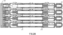
- Figure 27 and Figure 28 show to operate a plurality of cannons 10 in parallel.
- First left firing pin 12 is arranged in series with first right firing pin 12. This can be accomplished by attaching first left firing pin casing 11 to second left firing pin casing 11.
- First pressure media can enter into first left firing pin casing 11 through first pressure media entrance LP1.
- first pressure media can enter into first right firing pin casing 11 through first pressure media entrance LP2.
- Media is compressed and exits through a media exit centrally located between the two firing pins 12.
- Additional firing pins 12 can be added as desired.
- a plurality of canons 10 can be installed in channel block 104 which directs the media into channels between the plurality of cannons 10.
- the plurality of cannons 10 have more than one exit port.
- the plurality of cannons 10 have a single exit ports.
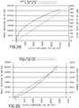
- Figure 29 shows how increasing pressure will also increase flow rate of the system.
- Figure 30 shows how charging the system with greater static pressure can result in more work done by the system.
- springs can provide additional work resulting in additional efficiency for the system.
- firing pin stern 16 is mechanically coupled to large spring 106, which is further mechanically coupled to firing pin outer casing 11.
- first pressure port to charge 56 is replaced with small spring 108, using spring force, as opposed to hydraulic force for the same affect.
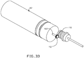
- outer casing 92 is perforated with turn shaft 102.
- Turn shaft 112 is mechanically coupled to gear 112.
- Gear 110 creates mechanical energy which can be used to turn motor 110.
- Mechanical energy from motor 110 can be used to turn another shaft 102 as in Figure 34 or to turn a generator to create electrical power as in Figure 35 .
- magnetic flux can be imparted onto shaft 102 or firing pin stern 16 to further increase system efficiency.
- a purpose of the present invention is to create the mechanical energy by moving a firing pin.
- the firing pin allows media to exit a cannon.
- Another purpose of the present invention is to create a pressure differential in a cannon that creates mechanical energy by displacing media.
Landscapes
- Engineering & Computer Science (AREA)
- General Engineering & Computer Science (AREA)
- Chemical & Material Sciences (AREA)
- Combustion & Propulsion (AREA)
- Mechanical Engineering (AREA)
- Power Engineering (AREA)
- Connection Of Motors, Electrical Generators, Mechanical Devices, And The Like (AREA)
- Hydraulic Motors (AREA)
- Engine Equipment That Uses Special Cycles (AREA)
Claims (14)
- Kraftmaschinenantriebssystem, das dafür konfiguriert ist, Explosionen von Medien zu nutzen, um mechanische Energie zu erzeugen, wobei das Kraftmaschinenantriebssystem aufweist:wenigstens eine Kanone (10), wobei jede Kanone dafür konfiguriert ist, die Medien zu verlagern, und ferner aufweist:ein Schlagbolzengehäuse (11), das dafür konfiguriert ist, einen Schlagbolzen (12) aufzunehmen;wobei der Schlagbolzen dafür konfiguriert ist, die mechanische Energie zu erzeugen, wenn dieser bewegt wird, was somit ermöglicht, dass die Medien aus der Kanone austreten;dadurch gekennzeichnet, dassder Schlagbolzen einen Kanal (54, 56) aufweist und mit einem zweiten Druckregler und mit einem ersten Druckregler mechanisch gekoppelt ist;der zweite Druckregler dafür konfiguriert ist zuzulassen, dass zweite Druckmedien in den Schlagbolzen eintreten;der erste Druckregler dafür konfiguriert ist, durch ein Solenoid zu gehen, um zu ermöglichen, dass erste Druckmedien in eine erste Druckkanonenöffnung, um zu laden, und in eine erste Drucköffnung, um zu zünden, eintreten;sich ein Schlagbolzenblockierungszylinder (26) in dem Kanal befindet und dafür ausgelegt ist, die Bewegung der zweiten Druckmedien in dem Kanal zu blockieren;ein Hut (38) mit dem Schlagbolzen mechanisch gekoppelt ist und an den Schlagbolzenblockierungszylinder unmittelbar angrenzt, wobei er ermöglicht, dass sich die zweiten Druckmedien über den Schlagbolzenblockierungszylinder hinaus durch den Kanal bewegen, wenn die ersten Druckmedien den Schlagbolzenblockierungszylinder über den Hut hinaus geschoben haben;wobei die zweiten Druckmedien dafür konfiguriert sind, die mechanische Energie zu erzeugen, die dafür konfiguriert ist, in dem Kraftmaschinenantriebssystem verwendet zu werden.
- Kraftmaschinenantriebssystem nach Anspruch 1, wobei die wenigstens eine Kanone in der Nähe eines Medienantriebssystems ist; wobei das Medienantriebssystem ferner aufweist: einen Vorratsbehälter, der die Medien enthält.
- Kraftmaschinenantriebssystem nach Anspruch 1, wobei die wenigstens eine Kanone in der Nähe eines Medienantriebssystems ist; wobei das Medienantriebssystem ferner aufweist: eine Pumpe, die zum Pumpen der Medien konfiguriert ist.
- Kraftmaschinenantriebssystem nach Anspruch 1, wobei die wenigstens eine Kanone in der Nähe eines Medienantriebssystems ist; wobei das Medienantriebssystem ferner aufweist: wenigstens einen Druckverstärker, um die Medien für die Druckbeaufschlagung aufzubereiten.
- Kraftmaschinenantriebssystem nach Anspruch 1, wobei die wenigstens eine Kanone in der Nähe eines Medienantriebssystems ist; wobei das Medienantriebssystem ferner aufweist: wenigstens ein Rückschlagventil.
- Kraftmaschinenantriebssystem nach Anspruch 1, wobei die wenigstens eine Kanone in der Nähe eines Medienantriebssystems ist; wobei das Medienantriebssystem ferner aufweist: wenigstens einen Druckspeicher, der an einem Regler befestigt ist und dafür konfiguriert ist, die Medien zu speichern.
- Kraftmaschinenantriebssystem nach Anspruch 1, wobei die wenigstens eine Kanone in der Nähe eines Medienantriebssystems ist; wobei das Medienantriebssystem ferner aufweist: wenigstens ein Solenoid, das an dem Schlagbolzengehäuse befestigt ist und dafür konfiguriert ist, die Medien zu verteilen.
- Kraftmaschinenantriebssystem nach Anspruch 1, das ferner ein Schlagbolzenrohr aufweist, das in der Nähe eines Rohrmedienauslasses (42) mit einer Rohrdichtung (58) mechanisch gekoppelt ist, wobei zweite Druckmedien durch den Rohrmedienauslass ausgestoßen werden, was den Antrieb veranlasst.
- Kraftmaschinenantriebssystem nach Anspruch 1, das ferner Dichtungen aufweist, die dafür konfiguriert sind, die Medien von allen Kanälen zu isolieren, und die dafür konfiguriert sind zu verhindern, dass Medien aus einem gesteuerten Auslass aus dem Kraftmaschinenantriebssystem unbeabsichtigt entweichen.
- Kraftmaschinenantriebssystem nach Anspruch 1, wobei die wenigstens eine Kanone eine Austrittsöffnung aufweist.
- Kraftmaschinenantriebssystem nach Anspruch 1, wobei die wenigstens eine Kanone eine Mehrzahl von Kanonen sind und wobei die eine Mehrzahl von Kanonen eine Austrittsöffnung gemeinsam nutzen.
- Kraftmaschinenantriebssystem nach Anspruch 1, wobei die wenigstens eine Kanone dafür konfiguriert ist, in einer synchronisierten Betriebsart zu arbeiten.
- Kraftmaschinenantriebssystem nach Anspruch 12, wobei die synchronisierte Betriebsart wenigstens einen Motor verwendet.
- Kraftmaschinenantriebssystem nach Anspruch 1, wobei die wenigstens eine Kanone dafür konfiguriert ist, in einer alternierenden Betriebsart zu arbeiten.
Applications Claiming Priority (3)
| Application Number | Priority Date | Filing Date | Title |
|---|---|---|---|
| US201361844753P | 2013-07-10 | 2013-07-10 | |
| US14/300,043 US9212626B2 (en) | 2013-07-10 | 2014-06-09 | Engine propulsion system |
| PCT/US2014/046231 WO2015006611A2 (en) | 2013-07-10 | 2014-07-10 | Engine propulsion system |
Publications (3)
| Publication Number | Publication Date |
|---|---|
| EP3019703A2 EP3019703A2 (de) | 2016-05-18 |
| EP3019703A4 EP3019703A4 (de) | 2016-08-03 |
| EP3019703B1 true EP3019703B1 (de) | 2018-04-11 |
Family
ID=52276012
Family Applications (1)
| Application Number | Title | Priority Date | Filing Date |
|---|---|---|---|
| EP14823797.7A Not-in-force EP3019703B1 (de) | 2013-07-10 | 2014-07-10 | Motorantriebssystem |
Country Status (4)
| Country | Link |
|---|---|
| US (3) | US9212626B2 (de) |
| EP (1) | EP3019703B1 (de) |
| CA (1) | CA2920970A1 (de) |
| WO (1) | WO2015006611A2 (de) |
Families Citing this family (2)
| Publication number | Priority date | Publication date | Assignee | Title |
|---|---|---|---|---|
| CN109736967B (zh) * | 2018-12-17 | 2021-02-26 | 西安近代化学研究所 | 一种变直径装药两端包覆装置 |
| CN112240570B (zh) * | 2020-10-20 | 2021-12-03 | 西安航天动力研究所 | 一种基于3d打印成型的旋流火炬点火器 |
Family Cites Families (34)
| Publication number | Priority date | Publication date | Assignee | Title |
|---|---|---|---|---|
| GB189410034A (en) * | 1894-05-23 | 1894-09-15 | Herbert John Haddan | An Improved Method of and Apparatus for Obtaining Motive Power by Means of Explosions. |
| GB260364A (en) * | 1925-08-08 | 1926-11-04 | John Leonard Charles | Improvements in internal combustion turbines |
| US2382526A (en) * | 1943-08-12 | 1945-08-14 | Automotive Engineering Company | Fluid motor |
| US2710067A (en) | 1951-02-28 | 1955-06-07 | Jet Helicopter Corp | Two-stage power jets and increased flame propagation for helicopters |
| US2981064A (en) | 1957-03-11 | 1961-04-25 | Leslie W Beaven | Engine of the expansion-reaction type |
| US3656658A (en) * | 1969-10-15 | 1972-04-18 | Silve J Iannetti | Intrusion protection system |
| US3951217A (en) * | 1974-09-03 | 1976-04-20 | Chicago Pneumatic Tool Company | Impact air wrench having a two position pressure regulator |
| US4185714A (en) | 1975-04-18 | 1980-01-29 | Davies Chadwick O | Implosive acoustic generator |
| US4578756A (en) * | 1982-12-28 | 1986-03-25 | United Technologies Corporation | Adaptive electrostatic engine diagnostics |
| US5553454A (en) * | 1995-03-20 | 1996-09-10 | Mortner; Sol E. | Compressed air engine system and method for generating electrical energy from the controlled release of compressed air |
| US5694764A (en) * | 1995-09-18 | 1997-12-09 | Sundstrand Corporation | Fuel pump assist for engine starting |
| US6634438B1 (en) * | 2001-06-01 | 2003-10-21 | Snap-On Technologies, Inc. | Pneumatic air tool with direct air path motor |
| US20030010514A1 (en) * | 2001-07-11 | 2003-01-16 | Taga Corporation | Single push button reverse valve system for a pneumatic tool |
| US7328570B2 (en) * | 2004-09-01 | 2008-02-12 | General Electric Company | Pulse detonation system for a gas turbine engine having multiple spools |
| US7598851B2 (en) * | 2005-10-03 | 2009-10-06 | Gm Global Technology Operations, Inc. | Method and apparatus for transmitting wireless signals on a mobile platform |
| US7526912B2 (en) * | 2005-10-31 | 2009-05-05 | General Electric Company | Pulse detonation engines and components thereof |
| US7669405B2 (en) * | 2005-12-22 | 2010-03-02 | General Electric Company | Shaped walls for enhancement of deflagration-to-detonation transition |
| US7315089B2 (en) * | 2006-02-23 | 2008-01-01 | Michael Carl Lambertson | Powertrain system comprising compressed air engine and method comprising same |
| US7802633B2 (en) * | 2006-09-18 | 2010-09-28 | Sp Air Kabushiki Kaisha | Reversible valve assembly for a pneumatic tool |
| DE102006061854B4 (de) * | 2006-12-21 | 2009-01-02 | N&G Facility Management Gmbh & Co.Kg | Fluidmotor mit verbesserter Bremswirkung |
| WO2009019718A1 (en) * | 2007-08-06 | 2009-02-12 | Dilip Daniel James | Rotary jet engine |
| US20090139199A1 (en) * | 2007-11-15 | 2009-06-04 | General Electric Company | Pulse detonation combustor valve for high temperature and high pressure operation |
| US7828091B2 (en) * | 2007-12-12 | 2010-11-09 | Wedderburn Jr Cosburn Henry | Air electric vehicle |
| JP2009162063A (ja) | 2007-12-28 | 2009-07-23 | Isuzu Motors Ltd | 噴流式蒸気エンジン |
| US9092029B2 (en) * | 2009-04-21 | 2015-07-28 | Hamilton Sundstrand Corporation | Vehicle monitoring system |
| US8277208B2 (en) * | 2009-06-11 | 2012-10-02 | Goodrich Pump & Engine Control Systems, Inc. | Split discharge vane pump and fluid metering system therefor |
| US8281594B2 (en) * | 2009-09-08 | 2012-10-09 | Siemens Energy, Inc. | Fuel injector for use in a gas turbine engine |
| US8181508B2 (en) * | 2009-09-10 | 2012-05-22 | GM Global Technology Operations LLC | Diagnostic systems and methods for a two-step valve lift mechanism |
| WO2011123690A1 (en) * | 2010-03-31 | 2011-10-06 | Fisker Automotive, Inc. | System and method for range calculation in vehicles |
| US8850807B2 (en) * | 2010-06-16 | 2014-10-07 | Hb Spider Llc | Compressed air engine |
| US20120131901A1 (en) * | 2010-11-30 | 2012-05-31 | General Electric Company | System and method for controlling a pulse detonation engine |
| US9909533B2 (en) * | 2011-07-29 | 2018-03-06 | Board Of Regents, The University Of Texas System | Pulsed detonation engine |
| RS20110375A1 (sr) * | 2011-08-24 | 2013-04-30 | Slobodan MARINKOVIĆ | Barutni motor i letilica pogonjena tim motorom |
| KR101275257B1 (ko) * | 2012-07-06 | 2013-06-17 | 최병열 | 물리적 에너지 저장시스템 |
-
2014
- 2014-06-09 US US14/300,043 patent/US9212626B2/en not_active Expired - Fee Related
- 2014-07-10 EP EP14823797.7A patent/EP3019703B1/de not_active Not-in-force
- 2014-07-10 CA CA2920970A patent/CA2920970A1/en not_active Abandoned
- 2014-07-10 WO PCT/US2014/046231 patent/WO2015006611A2/en not_active Ceased
- 2014-07-10 US US14/328,546 patent/US20150013303A1/en not_active Abandoned
-
2015
- 2015-11-05 US US14/933,342 patent/US20160053723A1/en not_active Abandoned
Non-Patent Citations (1)
| Title |
|---|
| None * |
Also Published As
| Publication number | Publication date |
|---|---|
| CA2920970A1 (en) | 2015-01-15 |
| US20150013302A1 (en) | 2015-01-15 |
| EP3019703A4 (de) | 2016-08-03 |
| US20150013303A1 (en) | 2015-01-15 |
| US9212626B2 (en) | 2015-12-15 |
| WO2015006611A2 (en) | 2015-01-15 |
| EP3019703A2 (de) | 2016-05-18 |
| US20160053723A1 (en) | 2016-02-25 |
| WO2015006611A3 (en) | 2015-03-12 |
Similar Documents
| Publication | Publication Date | Title |
|---|---|---|
| RU2621190C2 (ru) | Способ и система экстренного запуска установки генерирования энергии | |
| US10422285B2 (en) | Hydraulic device for emergency starting a turbine engine, propulsion system of a multi-engine helicopter provided with one such device, and corresponding helicopter | |
| EP3418670B1 (de) | Parallele brennerkonfiguration für die antriebsturbine eines unbemannten unterwasserfahrzeugs | |
| RU2684693C2 (ru) | Устройство содействия для силовой установки на твердом проперголе одномоторного вертолета, одномоторный вертолет, содержащий такое устройство, и соответствующий способ | |
| US6854409B1 (en) | Rotary electromagnetic launch tube | |
| WO2018044757A1 (en) | Multi-hybrid aircraft engine | |
| US9212626B2 (en) | Engine propulsion system | |
| CN104411919A (zh) | 物理能量储存系统及利用该物理能量储存系统的发电方法 | |
| US9097210B2 (en) | Turbine generator assembly for thrust vector control | |
| EP4081723B1 (de) | Elektrohydraulisches antriebssystem mit kombiniertem strommodul | |
| EP3203116B1 (de) | Elektrischer aktuator mit schubvektorsteuerung und verfahren zur herstellung desselben | |
| RU2634609C1 (ru) | Способ управления беспилотным летательным аппаратом и блок рулевых приводов для его осуществления | |
| RU2692884C1 (ru) | Электрогидравлический привод | |
| KR102185198B1 (ko) | 유압과 공압으로 작동하는 액츄에이터 어셈블리 및 그 제어방법 | |
| RU2692508C1 (ru) | Самоходная установка разминирования | |
| RU2197408C2 (ru) | Подводный аппарат с единым двигателем для надводного и подводного хода | |
| GB2238375A (en) | Gatling type gun system. | |
| RU2777124C1 (ru) | Самоходная машина (варианты) | |
| RU2605797C1 (ru) | Гидравлическая система летательного аппарата | |
| US20170204865A1 (en) | Emergency shutdown system for turbine pump assembly | |
| US20170204882A1 (en) | Turbine pump assembly with gas purged centrifugal impeller shrouds | |
| RU2468333C1 (ru) | Жидкостная ракета вытеснения (варианты) | |
| RU2729924C2 (ru) | Вспомогательная система привода вала пропульсивной системы вертолета | |
| CN117663901A (zh) | 适配器气体激发增推装置 | |
| RU2454545C2 (ru) | Способ увеличения мощности турбопоршневого двигателя |
Legal Events
| Date | Code | Title | Description |
|---|---|---|---|
| PUAI | Public reference made under article 153(3) epc to a published international application that has entered the european phase |
Free format text: ORIGINAL CODE: 0009012 |
|
| 17P | Request for examination filed |
Effective date: 20160208 |
|
| AK | Designated contracting states |
Kind code of ref document: A2 Designated state(s): AL AT BE BG CH CY CZ DE DK EE ES FI FR GB GR HR HU IE IS IT LI LT LU LV MC MK MT NL NO PL PT RO RS SE SI SK SM TR |
|
| AX | Request for extension of the european patent |
Extension state: BA ME |
|
| REG | Reference to a national code |
Ref country code: DE Ref legal event code: R079 Ref document number: 602014023879 Country of ref document: DE Free format text: PREVIOUS MAIN CLASS: F01D0001320000 Ipc: H02K0007180000 |
|
| A4 | Supplementary search report drawn up and despatched |
Effective date: 20160704 |
|
| RIC1 | Information provided on ipc code assigned before grant |
Ipc: F02C 5/02 20060101ALI20160628BHEP Ipc: F02C 5/12 20060101ALI20160628BHEP Ipc: H02K 7/18 20060101AFI20160628BHEP Ipc: F02C 5/04 20060101ALI20160628BHEP Ipc: F02C 3/16 20060101ALI20160628BHEP |
|
| DAX | Request for extension of the european patent (deleted) | ||
| GRAP | Despatch of communication of intention to grant a patent |
Free format text: ORIGINAL CODE: EPIDOSNIGR1 |
|
| INTG | Intention to grant announced |
Effective date: 20171016 |
|
| GRAS | Grant fee paid |
Free format text: ORIGINAL CODE: EPIDOSNIGR3 |
|
| GRAA | (expected) grant |
Free format text: ORIGINAL CODE: 0009210 |
|
| AK | Designated contracting states |
Kind code of ref document: B1 Designated state(s): AL AT BE BG CH CY CZ DE DK EE ES FI FR GB GR HR HU IE IS IT LI LT LU LV MC MK MT NL NO PL PT RO RS SE SI SK SM TR |
|
| REG | Reference to a national code |
Ref country code: GB Ref legal event code: FG4D |
|
| REG | Reference to a national code |
Ref country code: CH Ref legal event code: EP |
|
| REG | Reference to a national code |
Ref country code: AT Ref legal event code: REF Ref document number: 989024 Country of ref document: AT Kind code of ref document: T Effective date: 20180415 |
|
| REG | Reference to a national code |
Ref country code: IE Ref legal event code: FG4D |
|
| REG | Reference to a national code |
Ref country code: DE Ref legal event code: R096 Ref document number: 602014023879 Country of ref document: DE |
|
| REG | Reference to a national code |
Ref country code: NL Ref legal event code: MP Effective date: 20180411 |
|
| REG | Reference to a national code |
Ref country code: LT Ref legal event code: MG4D |
|
| PG25 | Lapsed in a contracting state [announced via postgrant information from national office to epo] |
Ref country code: NL Free format text: LAPSE BECAUSE OF FAILURE TO SUBMIT A TRANSLATION OF THE DESCRIPTION OR TO PAY THE FEE WITHIN THE PRESCRIBED TIME-LIMIT Effective date: 20180411 |
|
| PG25 | Lapsed in a contracting state [announced via postgrant information from national office to epo] |
Ref country code: PL Free format text: LAPSE BECAUSE OF FAILURE TO SUBMIT A TRANSLATION OF THE DESCRIPTION OR TO PAY THE FEE WITHIN THE PRESCRIBED TIME-LIMIT Effective date: 20180411 Ref country code: ES Free format text: LAPSE BECAUSE OF FAILURE TO SUBMIT A TRANSLATION OF THE DESCRIPTION OR TO PAY THE FEE WITHIN THE PRESCRIBED TIME-LIMIT Effective date: 20180411 Ref country code: LT Free format text: LAPSE BECAUSE OF FAILURE TO SUBMIT A TRANSLATION OF THE DESCRIPTION OR TO PAY THE FEE WITHIN THE PRESCRIBED TIME-LIMIT Effective date: 20180411 Ref country code: AL Free format text: LAPSE BECAUSE OF FAILURE TO SUBMIT A TRANSLATION OF THE DESCRIPTION OR TO PAY THE FEE WITHIN THE PRESCRIBED TIME-LIMIT Effective date: 20180411 Ref country code: FI Free format text: LAPSE BECAUSE OF FAILURE TO SUBMIT A TRANSLATION OF THE DESCRIPTION OR TO PAY THE FEE WITHIN THE PRESCRIBED TIME-LIMIT Effective date: 20180411 Ref country code: SE Free format text: LAPSE BECAUSE OF FAILURE TO SUBMIT A TRANSLATION OF THE DESCRIPTION OR TO PAY THE FEE WITHIN THE PRESCRIBED TIME-LIMIT Effective date: 20180411 Ref country code: NO Free format text: LAPSE BECAUSE OF FAILURE TO SUBMIT A TRANSLATION OF THE DESCRIPTION OR TO PAY THE FEE WITHIN THE PRESCRIBED TIME-LIMIT Effective date: 20180711 Ref country code: BG Free format text: LAPSE BECAUSE OF FAILURE TO SUBMIT A TRANSLATION OF THE DESCRIPTION OR TO PAY THE FEE WITHIN THE PRESCRIBED TIME-LIMIT Effective date: 20180711 |
|
| PG25 | Lapsed in a contracting state [announced via postgrant information from national office to epo] |
Ref country code: RS Free format text: LAPSE BECAUSE OF FAILURE TO SUBMIT A TRANSLATION OF THE DESCRIPTION OR TO PAY THE FEE WITHIN THE PRESCRIBED TIME-LIMIT Effective date: 20180411 Ref country code: HR Free format text: LAPSE BECAUSE OF FAILURE TO SUBMIT A TRANSLATION OF THE DESCRIPTION OR TO PAY THE FEE WITHIN THE PRESCRIBED TIME-LIMIT Effective date: 20180411 Ref country code: GR Free format text: LAPSE BECAUSE OF FAILURE TO SUBMIT A TRANSLATION OF THE DESCRIPTION OR TO PAY THE FEE WITHIN THE PRESCRIBED TIME-LIMIT Effective date: 20180712 Ref country code: LV Free format text: LAPSE BECAUSE OF FAILURE TO SUBMIT A TRANSLATION OF THE DESCRIPTION OR TO PAY THE FEE WITHIN THE PRESCRIBED TIME-LIMIT Effective date: 20180411 |
|
| REG | Reference to a national code |
Ref country code: AT Ref legal event code: MK05 Ref document number: 989024 Country of ref document: AT Kind code of ref document: T Effective date: 20180411 |
|
| PG25 | Lapsed in a contracting state [announced via postgrant information from national office to epo] |
Ref country code: PT Free format text: LAPSE BECAUSE OF FAILURE TO SUBMIT A TRANSLATION OF THE DESCRIPTION OR TO PAY THE FEE WITHIN THE PRESCRIBED TIME-LIMIT Effective date: 20180813 |
|
| REG | Reference to a national code |
Ref country code: DE Ref legal event code: R097 Ref document number: 602014023879 Country of ref document: DE |
|
| PG25 | Lapsed in a contracting state [announced via postgrant information from national office to epo] |
Ref country code: DK Free format text: LAPSE BECAUSE OF FAILURE TO SUBMIT A TRANSLATION OF THE DESCRIPTION OR TO PAY THE FEE WITHIN THE PRESCRIBED TIME-LIMIT Effective date: 20180411 Ref country code: AT Free format text: LAPSE BECAUSE OF FAILURE TO SUBMIT A TRANSLATION OF THE DESCRIPTION OR TO PAY THE FEE WITHIN THE PRESCRIBED TIME-LIMIT Effective date: 20180411 Ref country code: EE Free format text: LAPSE BECAUSE OF FAILURE TO SUBMIT A TRANSLATION OF THE DESCRIPTION OR TO PAY THE FEE WITHIN THE PRESCRIBED TIME-LIMIT Effective date: 20180411 Ref country code: SK Free format text: LAPSE BECAUSE OF FAILURE TO SUBMIT A TRANSLATION OF THE DESCRIPTION OR TO PAY THE FEE WITHIN THE PRESCRIBED TIME-LIMIT Effective date: 20180411 Ref country code: RO Free format text: LAPSE BECAUSE OF FAILURE TO SUBMIT A TRANSLATION OF THE DESCRIPTION OR TO PAY THE FEE WITHIN THE PRESCRIBED TIME-LIMIT Effective date: 20180411 Ref country code: CZ Free format text: LAPSE BECAUSE OF FAILURE TO SUBMIT A TRANSLATION OF THE DESCRIPTION OR TO PAY THE FEE WITHIN THE PRESCRIBED TIME-LIMIT Effective date: 20180411 |
|
| REG | Reference to a national code |
Ref country code: DE Ref legal event code: R119 Ref document number: 602014023879 Country of ref document: DE |
|
| PLBE | No opposition filed within time limit |
Free format text: ORIGINAL CODE: 0009261 |
|
| STAA | Information on the status of an ep patent application or granted ep patent |
Free format text: STATUS: NO OPPOSITION FILED WITHIN TIME LIMIT |
|
| PG25 | Lapsed in a contracting state [announced via postgrant information from national office to epo] |
Ref country code: IT Free format text: LAPSE BECAUSE OF FAILURE TO SUBMIT A TRANSLATION OF THE DESCRIPTION OR TO PAY THE FEE WITHIN THE PRESCRIBED TIME-LIMIT Effective date: 20180411 Ref country code: SM Free format text: LAPSE BECAUSE OF FAILURE TO SUBMIT A TRANSLATION OF THE DESCRIPTION OR TO PAY THE FEE WITHIN THE PRESCRIBED TIME-LIMIT Effective date: 20180411 |
|
| REG | Reference to a national code |
Ref country code: CH Ref legal event code: PL |
|
| 26N | No opposition filed |
Effective date: 20190114 |
|
| GBPC | Gb: european patent ceased through non-payment of renewal fee |
Effective date: 20180711 |
|
| PG25 | Lapsed in a contracting state [announced via postgrant information from national office to epo] |
Ref country code: LU Free format text: LAPSE BECAUSE OF NON-PAYMENT OF DUE FEES Effective date: 20180710 Ref country code: MC Free format text: LAPSE BECAUSE OF FAILURE TO SUBMIT A TRANSLATION OF THE DESCRIPTION OR TO PAY THE FEE WITHIN THE PRESCRIBED TIME-LIMIT Effective date: 20180411 |
|
| REG | Reference to a national code |
Ref country code: BE Ref legal event code: MM Effective date: 20180731 |
|
| REG | Reference to a national code |
Ref country code: IE Ref legal event code: MM4A |
|
| PG25 | Lapsed in a contracting state [announced via postgrant information from national office to epo] |
Ref country code: FR Free format text: LAPSE BECAUSE OF NON-PAYMENT OF DUE FEES Effective date: 20180731 Ref country code: LI Free format text: LAPSE BECAUSE OF NON-PAYMENT OF DUE FEES Effective date: 20180731 Ref country code: CH Free format text: LAPSE BECAUSE OF NON-PAYMENT OF DUE FEES Effective date: 20180731 Ref country code: IE Free format text: LAPSE BECAUSE OF NON-PAYMENT OF DUE FEES Effective date: 20180710 Ref country code: GB Free format text: LAPSE BECAUSE OF NON-PAYMENT OF DUE FEES Effective date: 20180711 Ref country code: DE Free format text: LAPSE BECAUSE OF NON-PAYMENT OF DUE FEES Effective date: 20190201 |
|
| PG25 | Lapsed in a contracting state [announced via postgrant information from national office to epo] |
Ref country code: BE Free format text: LAPSE BECAUSE OF NON-PAYMENT OF DUE FEES Effective date: 20180731 Ref country code: SI Free format text: LAPSE BECAUSE OF FAILURE TO SUBMIT A TRANSLATION OF THE DESCRIPTION OR TO PAY THE FEE WITHIN THE PRESCRIBED TIME-LIMIT Effective date: 20180411 |
|
| PG25 | Lapsed in a contracting state [announced via postgrant information from national office to epo] |
Ref country code: MT Free format text: LAPSE BECAUSE OF NON-PAYMENT OF DUE FEES Effective date: 20180710 |
|
| PG25 | Lapsed in a contracting state [announced via postgrant information from national office to epo] |
Ref country code: TR Free format text: LAPSE BECAUSE OF FAILURE TO SUBMIT A TRANSLATION OF THE DESCRIPTION OR TO PAY THE FEE WITHIN THE PRESCRIBED TIME-LIMIT Effective date: 20180411 |
|
| PG25 | Lapsed in a contracting state [announced via postgrant information from national office to epo] |
Ref country code: CY Free format text: LAPSE BECAUSE OF FAILURE TO SUBMIT A TRANSLATION OF THE DESCRIPTION OR TO PAY THE FEE WITHIN THE PRESCRIBED TIME-LIMIT Effective date: 20180411 Ref country code: MK Free format text: LAPSE BECAUSE OF NON-PAYMENT OF DUE FEES Effective date: 20180411 Ref country code: HU Free format text: LAPSE BECAUSE OF FAILURE TO SUBMIT A TRANSLATION OF THE DESCRIPTION OR TO PAY THE FEE WITHIN THE PRESCRIBED TIME-LIMIT; INVALID AB INITIO Effective date: 20140710 |
|
| PG25 | Lapsed in a contracting state [announced via postgrant information from national office to epo] |
Ref country code: IS Free format text: LAPSE BECAUSE OF FAILURE TO SUBMIT A TRANSLATION OF THE DESCRIPTION OR TO PAY THE FEE WITHIN THE PRESCRIBED TIME-LIMIT Effective date: 20180811 |