EP3019860B1 - Anordnung für eine kolonne und verfahren zum ersetzen eines rohrförmigen gehäuses in solch einer anordnung für eine kolonne - Google Patents
Anordnung für eine kolonne und verfahren zum ersetzen eines rohrförmigen gehäuses in solch einer anordnung für eine kolonne Download PDFInfo
- Publication number
- EP3019860B1 EP3019860B1 EP14823662.3A EP14823662A EP3019860B1 EP 3019860 B1 EP3019860 B1 EP 3019860B1 EP 14823662 A EP14823662 A EP 14823662A EP 3019860 B1 EP3019860 B1 EP 3019860B1
- Authority
- EP
- European Patent Office
- Prior art keywords
- tubular housing
- adaptor
- arrangement
- column
- end unit
- Prior art date
- Legal status (The legal status is an assumption and is not a legal conclusion. Google has not performed a legal analysis and makes no representation as to the accuracy of the status listed.)
- Active
Links
Images



Classifications
-
- C—CHEMISTRY; METALLURGY
- C07—ORGANIC CHEMISTRY
- C07K—PEPTIDES
- C07K1/00—General methods for the preparation of peptides, i.e. processes for the organic chemical preparation of peptides or proteins of any length
- C07K1/02—General methods for the preparation of peptides, i.e. processes for the organic chemical preparation of peptides or proteins of any length in solution
-
- B—PERFORMING OPERATIONS; TRANSPORTING
- B01—PHYSICAL OR CHEMICAL PROCESSES OR APPARATUS IN GENERAL
- B01D—SEPARATION
- B01D15/00—Separating processes involving the treatment of liquids with solid sorbents; Apparatus therefor
- B01D15/08—Selective adsorption, e.g. chromatography
- B01D15/10—Selective adsorption, e.g. chromatography characterised by constructional or operational features
- B01D15/22—Selective adsorption, e.g. chromatography characterised by constructional or operational features relating to the construction of the column
-
- B—PERFORMING OPERATIONS; TRANSPORTING
- B01—PHYSICAL OR CHEMICAL PROCESSES OR APPARATUS IN GENERAL
- B01J—CHEMICAL OR PHYSICAL PROCESSES, e.g. CATALYSIS OR COLLOID CHEMISTRY; THEIR RELEVANT APPARATUS
- B01J19/00—Chemical, physical or physico-chemical processes in general; Their relevant apparatus
- B01J19/24—Stationary reactors without moving elements inside
- B01J19/2415—Tubular reactors
-
- C—CHEMISTRY; METALLURGY
- C07—ORGANIC CHEMISTRY
- C07H—SUGARS; DERIVATIVES THEREOF; NUCLEOSIDES; NUCLEOTIDES; NUCLEIC ACIDS
- C07H1/00—Processes for the preparation of sugar derivatives
- C07H1/06—Separation; Purification
-
- C—CHEMISTRY; METALLURGY
- C07—ORGANIC CHEMISTRY
- C07H—SUGARS; DERIVATIVES THEREOF; NUCLEOSIDES; NUCLEOTIDES; NUCLEIC ACIDS
- C07H21/00—Compounds containing two or more mononucleotide units having separate phosphate or polyphosphate groups linked by saccharide radicals of nucleoside groups, e.g. nucleic acids
-
- C—CHEMISTRY; METALLURGY
- C07—ORGANIC CHEMISTRY
- C07K—PEPTIDES
- C07K1/00—General methods for the preparation of peptides, i.e. processes for the organic chemical preparation of peptides or proteins of any length
- C07K1/14—Extraction; Separation; Purification
- C07K1/16—Extraction; Separation; Purification by chromatography
-
- G—PHYSICS
- G01—MEASURING; TESTING
- G01N—INVESTIGATING OR ANALYSING MATERIALS BY DETERMINING THEIR CHEMICAL OR PHYSICAL PROPERTIES
- G01N30/00—Investigating or analysing materials by separation into components using adsorption, absorption or similar phenomena or using ion-exchange, e.g. chromatography or field flow fractionation
- G01N30/02—Column chromatography
- G01N30/60—Construction of the column
- G01N30/6004—Construction of the column end pieces
- G01N30/6021—Adjustable pistons
-
- G—PHYSICS
- G01—MEASURING; TESTING
- G01N—INVESTIGATING OR ANALYSING MATERIALS BY DETERMINING THEIR CHEMICAL OR PHYSICAL PROPERTIES
- G01N30/00—Investigating or analysing materials by separation into components using adsorption, absorption or similar phenomena or using ion-exchange, e.g. chromatography or field flow fractionation
- G01N30/02—Column chromatography
- G01N30/60—Construction of the column
- G01N30/6047—Construction of the column with supporting means; Holders
-
- G—PHYSICS
- G01—MEASURING; TESTING
- G01N—INVESTIGATING OR ANALYSING MATERIALS BY DETERMINING THEIR CHEMICAL OR PHYSICAL PROPERTIES
- G01N30/00—Investigating or analysing materials by separation into components using adsorption, absorption or similar phenomena or using ion-exchange, e.g. chromatography or field flow fractionation
- G01N30/02—Column chromatography
- G01N30/88—Integrated analysis systems specially adapted therefor, not covered by a single one of the groups G01N30/04 - G01N30/86
- G01N2030/8809—Integrated analysis systems specially adapted therefor, not covered by a single one of the groups G01N30/04 - G01N30/86 analysis specially adapted for the sample
- G01N2030/8813—Integrated analysis systems specially adapted therefor, not covered by a single one of the groups G01N30/04 - G01N30/86 analysis specially adapted for the sample biological materials
- G01N2030/8831—Integrated analysis systems specially adapted therefor, not covered by a single one of the groups G01N30/04 - G01N30/86 analysis specially adapted for the sample biological materials involving peptides or proteins
-
- G—PHYSICS
- G01—MEASURING; TESTING
- G01N—INVESTIGATING OR ANALYSING MATERIALS BY DETERMINING THEIR CHEMICAL OR PHYSICAL PROPERTIES
- G01N30/00—Investigating or analysing materials by separation into components using adsorption, absorption or similar phenomena or using ion-exchange, e.g. chromatography or field flow fractionation
- G01N30/02—Column chromatography
- G01N30/60—Construction of the column
- G01N30/6004—Construction of the column end pieces
- G01N30/6017—Fluid distributors
Definitions
- This invention relates to an arrangement for a column according to claim 1 and a method for substituting a tubular housing in an arrangement for a column according to claim 10.
- the chromatography technique is widely used in different forms for separating chemical and biological substances and there are many applications in compound preparation, purification and analysis. Liquid chromatography is of particular importance in the pharmaceutical and biological industries for the preparation, purification and analysis of proteins, peptides and nucleic acids.
- a typical liquid chromatography apparatus has an upright housing in which a bed of packing material, which is usually in particulate in nature and consists of a porous medium, rests against a permeable retaining layer.
- a liquid mobile phase enters through an inlet, for example at the end of an adaptor rod which has an elongated extension within the column.
- the liquid mobile phase thereafter enters an adaptor assembly comprising a distributor plate which distributes the liquid mobile phase through a porous, perforated filter, mesh, frit or net, arranged on the adaptor plate.
- the liquid mobile phase thereafter moves through the bed of packing material and is finally removed via an outlet, typically through a second filter, mesh, frit or net and a second distributor plate.
- Columns used in liquid chromatography typically comprise a tubular housing enclosing the porous chromatography medium through which the carrier liquid or mobile phase flows, with separation of substances or analytes taking place between the mobile phase and solid phase of the porous medium.
- the porous medium is enclosed in the column as a packed bed, generally formed by consolidating a suspension of discrete particles, known as slurry that is pumped, poured or sucked into the column, usually from a bore or nozzle located at the tubular housing or at one end of the column.
- Conventional distribution systems for use in liquid chromatography comprise a distributor plate which comprises channels arranged in a pattern to substantially uniform distribute the fluid over the plate.
- the distributor plate is perforated with holes or openings which lead the fluid from the channels and uniformly into the packed bed.
- the backing plate or the lowermost, second end unit of the chromatography columns generally acts as a support for the column, being itself supported on legs or some other stand arrangement positioned on the floor which allows clearance for an outlet pipe work projecting beneath the column.
- Such known chromatography apparatuses are provided with a column having a fixed high and diameter and thus a fixed volume.
- chromatography apparatuses are provided with a column having a fixed high and diameter and thus a fixed volume.
- purification and analysis different sizes of chromatography apparatus must be used in order to achieve a proper result. Therefore, most of the pharmaceutical and biological industries are equipped with a large number of chromatography apparatuses of different sizes.
- An oligonucleotide is a macromolecule comprising a sequence of nucleosides, each of which includes a sugar and a base. Each nucleoside is separated from adjacent nucleosides with an internucleoside linkage, which effectively serves to bond the nucleosides together.
- the internucleoside linkage is most commonly a phosphate, which may be substituted with a variety of substitutents at a non-bridging oxygen atom.
- One method used for synthesizing oligonucleotides is the phosphoramidite method.
- a solid support is provided in a reaction vessel and a large number of DMT-protected nucleosides are fixed to the support.
- a deprotectant acting through a detritylation mechanism is added to remove the DMT from nucleoside, and thus to "deprotect" that one hydroxyl.
- the last nucleoside in the sequence has one hydroxyl that is ready to receive a next amidite.
- nucleoside phosphoramidites hereafter “amidites” dissolved in a solvent such as acetonitrile (ACN)
- ACN acetonitrile
- An activator is also introduced into the vessel with the amidites.
- the phosphorus in the amidites bonds with the oxygen in the hydroxyl, thus providing support-bound nucleotides.
- excess amidites are flushed from the vessel with ACN.
- an oxidizing agent is added to convert the trivalent phosphorous to pentavalent.
- a capping agent is added in a fourth step to block all the unprotected hydroxyls from reacting with amidites introduced at a later stage. Thereafter, ACN is again introduced to flush out the capping agent.
- oligonucleotides In larger quantities, the production of oligonucleotides raises several concerns. Because of the interest in using synthesized oligonucleotides for human use, the oligonucleotides must have a high degree of homogeneity. Meanwhile, competing concerns affect the efficient use of materials, particularly the amidites and the ACN. While an excess amount of amidites is needed to ensure that as many as possible of the nascent oligonucleotides react with newly introduced amidites, the quantity of amidites introduced into the vessel should not be too excessive and wasteful. It is also desirable to reduce the amount of ACN that is used, while still flushing out, or at least diluting, leftover amidites as much as possible. If the flushing is insufficient, leftover amidites in the vessel or in various conduits leading to the column can produce nonhomogeneous sequences.
- a known machine uses a flow-through design in which various conduits, pumps, and valves are constantly filled with liquid. Liquid introduced into a column displaces previously introduced liquid.
- This flow-through system is distinguished from a "batch" system in which liquids are introduced into a reaction vessel, the introduced liquids are flushed out, and the steps of introducing and flushing liquids is repeated.
- the liquids are provided to the vessel by gas pressure and not with pumps. This approach can be used because a batch process has gaps in the flow of fluid.
- each of the pumps is initially calibrated. During operation, the pumps are activated a certain period of time to provide the desired quantities of liquid. Periodically, the pumps must be rechecked and recalibrated to avoid problems that can result from drifting in the pump.
- US 5,641,459 shows a machine for synthesizing oligonucleotides provided with a control system which control the volumes of liquid that are introduced during operation.
- the control system avoids the need to recalibrate due to drifting because valves are regulated during operation.
- different capping agents can be mixed together in the valve; the activator and amidites also can be simultaneously introduced and mixed.
- the valves in the modules are also coupled to receive a flushing agent.
- Oligonucleotide and peptide synthesis use large volumes of expensive reagents and solvents.
- the bed volume increases during the synthesis, partly due to swelling solid support and partly due to synthesized product.
- synthesis is performed in a vessel with a fixed volume the distribution of the reagent over the whole accessible area for neuclotide/peptide binding may be unfavourable.
- an access of solvent which dilutes the reagents during synthesis may affect the synthesis performance and reliability, since low concentration means slower kinetics.
- the synthesis may take a few hours or a week long depending on the amount and volume of the product to be synthesized. Therefore, any manual handling throughout the synthesis process should be avoided.
- An objective problem to be solved by the present invention is to increase the flexibility of a column.
- Another objective problem to be solved is to reduce the number of columns of different sizes when performing preparation, purification and analysis of different substances.
- Still another objective problem to be solved is to reduce any manual handling throughout the process for synthesizing peptides and/or oligonucleotides.
- the arrangement for the column, the method for conducting peptide and/or oligonucleotide synthesis in a column, which is not part of the claimed invention, the computer program for controlling peptide and/or oligonucleotide synthesis in a column, which is not part of the claimed invention, and the computer program product comprising program code, which is not part of the claimed invention, increase the flexibility of a column and reduce the number of columns of different sizes when performing preparation, purification and analysis of different substances. Also, manual handling throughout the process for synthesizing peptides and/or oligonucleotides is reduced.
- Controlling of the adjustable adaptor in the head space above the bed avoids any manual handling throughout the synthesis run, which may take a few hours or a week long.
- the programmed motorized automated adaptor movement and the distribution system enable the optimized automated synthesis concept with an even distribution of reagents and make it possible to minimize the dilution of the reagents and also to minimize the usage of expensive solvents.
- the combination of the arrangement for the column for peptide and/or oligonucleotide synthesis with a programmed motorized automated adaptor solves the automation of the synthesis.
- Using separate adaptable cassette inserts or exchangeable tubes and distributors with the size and dimension needed for the synthesis increase the flexibility of the arrangement and reduce the number of apparatuses of different sizes when performing preparation, purification and synthesis of different substances.
- the disclosure comprises an arrangement for a column, a method for conducting peptide and/or oligonucleotide synthesis in a column, a computer program for controlling peptide and/or oligonucleotide synthesis in a column and a computer program product comprising program code that will be exemplified in the description set forth hereinafter and the scope of the invention will be indicated in the claims.
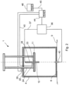
- Fig. 1 shows a cross sectional view of an arrangement 1 for a column 2 according to the present invention.
- the arrangement 1 comprising a stand 4 which is provided with a platform 6 adapted to receive a second end 8 or a bottom of a tubular housing 10 of the column 2 and for supporting the arrangement 1 on a floor 9.
- a first end unit 11 is removably connected to a first end 13 of the tubular housing 10.
- An adaptor rod 12 is connected to an adaptor assembly 14, which is movable within said tubular housing 10.
- the adaptor assembly 14 comprises a distributor plate 16 and a porous, perforated filter 18, which is arranged on the distributor plate 16.
- the adaptor rod 12 is arranged to extend through an opening 20 in the first end unit 11.
- a frame 22 is connected to the first end unit 11, which frame 22 and first end unit 11 can be lifted and lowered in a substantially vertical direction, so that the tubular housing 10 may be removed and substituted for another tubular housing 10' with different dimensions in relation to the removed tubular housing 10 when the frame 22 and first end unit 11 are lifted.
- the first end unit 11 is adapted to be connectable to different tubular housings 10 with different diameters.
- the adaptor rod 12 is removably connected to the adaptor assembly 14, so that the adaptor assembly 14 may be removed and substituted for another adaptor assembly 14' adapted to the substituted tubular housing 10'.
- the tubular housing 10 has preferably a cylindrical cross section. However, it is possible to provide the tubular housing 10 with another cross section, for example with a square cross section.
- the adaptor assembly 14 has a form which coincides with the form of the tubular housing 10.
- a first actuating means 24 is arranged to lift and lower the adaptor rod 12 in a substantially vertical direction in relation to the first end unit 11.
- the first actuating means 24 is a first electrical motor.
- the first actuating means 24 may also be a pneumatic or hydraulic cylinder.
- a second actuating means 26 is arranged to lift and lower the frame 22.
- the second actuating means 26 is a second electrical motor.
- the second actuating means 26 may also be a pneumatic or hydraulic cylinder.
- the wall 28 and the second end 8 or bottom of the tubular housing 10 together with the first end unit 11 form a fluid space 30 and bed space 32, which spaces 30, 32 both are fluid tight and are capable of withstanding high operating pressures.
- the bed space 32 is defined by the wall 28 of the tubular housing 10, the bottom and the adaptor assembly 14 connected to the adaptor rod 12.
- the bed space 32 is filled with a bed of packing material 34, which is usually particulate in nature and comprises or consists of a porous medium.
- a liquid pump 36 is connected to the adaptor rod 12 and to the tubular housing 10 by means of conduits or pipes 37.
- a liquid mobile phase is arranged to enter through an inlet at the end of the adaptor rod 12 and flows through a central channel 38 in the adaptor rod 12 and further to the adaptor assembly 14.
- the liquid mobile phase thereafter moves through the bed of packing material 34 and is finally removed via an outlet 40 in the bottom of the tubular housing 10.
- the packing material 34 enclosed in the column 2 as a packed bed is generally formed by consolidating a suspension of discrete particles, known as slurry that is pumped, poured or sucked into the column 2 from a bore or nozzle 42 located at the tubular housing 10.
- the distributor plate 16 comprises channels (not disclosed) arranged in a pattern to substantially uniform distribute the liquid mobile phase over the plate 16.
- the distributor plate 16 is perforated with holes or openings (not disclosed) which lead the liquid mobile phase from the channels and uniformly into the packing material 34.
- An electronic control unit 44 is connected to the first actuating means 24, to the second actuating means 26 and to the liquid pump 36, e.g. by means of electrical wires 45.
- the control unit 44 is arranged to control the first actuating means 24, the second actuating means 26 and the liquid pump 36.
- another computer 46 may also be connected to the control unit 44, e.g. by electrical wires 45.
- the control unit 44 and the computer 46 are both provided with a computer program P stored in an executable way or compressed manner in a memory M and/or in a readable/writable memory R.
- Fig. 2 shows a cross sectional view of the arrangement 1 in fig. 1 with a lifted first end unit 11.
- the control unit 44 has instructed the second electrical motor 26 to lift the frame 22 and thereby also the first end unit 11.
- the first electrical motor 24 has been instructed by the control unit 44 to lift adaptor rod 12 in relation to the first end unit 11.
- the tubular housing 10 and the adaptor assembly 14 have been removed from the arrangement 1.
- Fig. 3 shows a cross sectional view of the arrangement 1 in fig. 1 with a substituted tubular housing 10' and adaptor assembly 14'.
- Both first and second electrical motors 24, 26 have been instructed by the control unit 44 to lower the frame 22 and the adaptor rod 12, so that the first end unit 11 has been connected to the first end 13 of the tubular housing 10.
- the new tubular housing 10' has a diameter and height which are smaller in size than the previous tubular housing 10.
- a wide range of column 2 capacities is possible, typically ranging from 0.1 to 2000 liters.
- the column 2 is adapted for peptide and/or oligonucleotide synthesis.
- the arrangement 1 according to the invention can be used as a chromatography column.
- Fig. 4 shows a block scheme of the method for substituting the tubular housing 10 in the arrangement 1 for the column 2 according to the present invention. The method comprising the steps of:
- the method comprises the further steps of:
- Figures 5a - 5e shows cross sectional views of a column 2 with an adaptor rod 12 and adaptor assembly 14 in different positions when performing a method of conducting peptide and/or oligonucleotide synthesis in the column 2.
- An oligonucleotide is a macromolecule comprising a sequence of nucleosides, each of which includes a sugar and a base. Each nucleoside is separated from adjacent nucleosides with an internucleoside linkage, which effectively serves to bond the nucleosides together. A number of different sugars and bases can be used.
- the internucleoside linkage is most commonly a phosphate, which may be substituted with a variety of substitutents at a non-bridging oxygen atom.
- the method used for synthesizing peptides and oligonucleotides comprises a plurality of steps.
- the packing material 34 is provided in the column 2 and a large number of DMT-protected nucleosides are fixed to the support.
- Fig. 5a shows a first detritylation step where a deprotectant acting through a detritylation mechanism, is added to remove the DMT from nucleoside, and thus to "deprotect" that one hydroxyl.
- the last nucleoside in the sequence has one hydroxyl that is ready to receive a next amidite.
- Due to the product is building up on the media the volume of packing material 34 increases during the synthesis, partly due to swelling of the packing material 34 and partly due to swelling of the synthesized product.
- the column 2 is packed with packing material 34 about 50% - 60% of total volume of the column 2, and for example with the concentration of: 111 mg/ml.
- the adaptor assembly 14 is positioned above the surface of and in contact with the packing material 34. This step is preferably performed in toluene as a deprotectant.
- Fig. 5b shows a second coupling step where nucleoside phosphoramidites, hereafter mentioned as "amidites", dissolved in a solvent such as acetonitrile, ACN, are introduced into the vessel.
- An activator is also introduced into the vessel with the amidites.
- the phosphorus in the amidites bonds with the oxygen in the hydroxyl, thus providing support-bound nucleotides.
- excess amidites are flushed from the vessel with acetonitrile. Since the packing material 34 contracts in acetonitrile the adaptor assembly 14 is automatically lowered, for example by 3% - 4% in the coupling step.
- the length the adaptor assembly 14 is automatically lowered depends on the characteristics and the volume of the packing material 34 and also the dimensions of the tubular housing 10.
- Fig. 5c shows a third oxidation step where an oxidizing agent is added to convert the trivalent phosphorous to pentavalent. Since the packing material 34 swells in the oxidation step the adaptor assembly 14 is automatically raised by 3% - 4% in relation to the level in the first detritylation step.
- a capping agent is added in a fourth capping step disclosed in Fig. 5d to block all the unprotected hydroxyls from reacting with amidites introduced at a later stage.
- the adaptor assembly 14 is automatically lowered to rest on the surface of the packing material 34, which corresponds to the level in the first detritylation step. Thereafter, acetonitrile again is introduced to flush out the capping agent.
- Fig. 5e shows the process after the support is stable.
- the adaptor assembly 14 is starting on a level which is 3% - 4% higher than the level of the first step in the previous step in order to compensate for the swelling of the product and packing material 34.
- Fig. 6 shows a block scheme of the method for conducting peptide and/or oligonucleotide synthesis. The method comprises the steps of:
- the method comprises the further steps of:
- the deprotectant in step d), the aminoacid/amidite in step e), the oxidizing agent in step g) and the capping agent in step i) are introduced through the channel 38 in the adaptor rod 12 and through the adaptor assembly 14.
- a second distributor plate (not disclosed) is preferbly arranged at the bottom 8 of the tubular housing 10 to uniformly distribute the substances into the packing material 10.
- a computer program P which comprises routines for controlling peptide and/or oligonucleotide synthesis in a column 2 but does not form part of the present invention.
- the computer program P may comprise routines for controlling the liquid pump 36 which is connected to the adaptor rod 12 and to the tubular housing 10.
- the mobile phase with different substances according to above is arranged to enter through the inlet at the end of the adaptor rod 12 and to flow through the central channel 38 in the adaptor rod 12 and further to the adaptor assembly 14.
- the liquid mobile phase thereafter moves through the bed of packing material 34 and is finally removed via the outlet 40 in the bottom of the tubular housing 10 and back to the liquid pump 36.
- the computer program P may comprise routines for controlling the first actuating means 24 arranged to lift and lower the adaptor rod 12 in a substantially vertical direction in relation to the first end unit 11.
- the first actuating means 24 is preferably the first electrical motor or may be a pneumatic or hydraulic cylinder.
- the length of movement of the adaptor assembly 14 depends on the characteristics and the volume of the packing material 34 and also the dimentions of the tubular housing 10. Based on experience the adaptor assembly 14 is arranged to move a distance suitable for compensating for the swelling of the packing material 34.
- the computer program P may comprise routines for controlling the second actuating means 26 arranged to lift and lower the frame 22.
- the second actuating means 26 is preferably the second electrical motor or may be a pneumatic or hydraulic cylinder.
- the program P may be stored in an executable way or compressed manner in the memory M and/or in the readable/writable memory R.
- parts and surfaces being in contact with a process fluid are suitably selected from materials that are in accordance with typical material requirements in (bio-)pharmaceutical manufacturing or food grade quality.
- materials are suitably in compliance with USP Class VI and 21 CFR 177.
- they are suitably of animal-free origin and compliance to EMEA/41O/01.
Landscapes
- Chemical & Material Sciences (AREA)
- Organic Chemistry (AREA)
- Life Sciences & Earth Sciences (AREA)
- Health & Medical Sciences (AREA)
- Biochemistry (AREA)
- General Health & Medical Sciences (AREA)
- Molecular Biology (AREA)
- Analytical Chemistry (AREA)
- Genetics & Genomics (AREA)
- Biotechnology (AREA)
- Engineering & Computer Science (AREA)
- General Physics & Mathematics (AREA)
- Pathology (AREA)
- Immunology (AREA)
- Physics & Mathematics (AREA)
- Chemical Kinetics & Catalysis (AREA)
- Biophysics (AREA)
- Medicinal Chemistry (AREA)
- Proteomics, Peptides & Aminoacids (AREA)
- Peptides Or Proteins (AREA)
- Saccharide Compounds (AREA)
- Apparatus Associated With Microorganisms And Enzymes (AREA)
- Treatment Of Liquids With Adsorbents In General (AREA)
Claims (10)
- Anordnung für eine Chromatographiesäule (2), umfassend:einen Ständer (4), der mit einer Plattform (6) versehen ist, die angepasst ist, um ein zweites Ende (8) eines rohrförmigen Gehäuses (10) der Chromatographiesäule aufzunehmen und zum Tragen der Anordnung (1) auf dem Boden (9);eine Adapterbaugruppe (14), die innerhalb des rohrförmigen Gehäuses (10) beweglich ist;eine erste Endeinheit (11), die ein erstes Ende, das mit einem Rahmen (22) verbunden ist, und ein gegenüberliegendes zweites Ende aufweist, das lösbar mit einem ersten Ende (13) des rohrförmigen Gehäuses (10) verbindbar ist; undeine Adapterstange (12), die mit der Adapterbaugruppe (14) verbindbar ist, wobei die Adapterstange (12) angeordnet ist, um sich durch eine Öffnung (20) in der ersten Endeinheit (11) zu erstrecken;dadurch gekennzeichnet, dass der Rahmen (22) und die erste Endeinheit (11) in einer im Wesentlichen vertikalen Richtung in Bezug auf den Ständer (4), auf dem das rohrförmige Gehäuse (10) ruht, angehoben und abgesenkt werden können, was ermöglicht, dass das rohrförmige Gehäuse (10) entfernt wird und durch ein anderes rohrförmiges Gehäuse (10') mit unterschiedlichem Durchmesser in Bezug auf das entfernte rohrförmige Gehäuse (10) ersetzt wird, wenn der Rahmen (22) und die erste Endeinheit (11) angehoben sind, wobei die erste Endeinheit (11) angepasst ist, um mit unterschiedlichen rohrförmigen Gehäusen (10) mit unterschiedlichen Durchmessern verbindbar zu sein,wobei die Adapterstange (12) lösbar mit der Adapterbaugruppe (14) verbunden ist, sodass die Adapterbaugruppe (14) entfernt und durch eine andere Adapterbaugruppe (14) ersetzt werden kann, die dem ersetzten rohrförmigen Gehäuse (10) angepasst ist.
- Anordnung nach Anspruch 1, wobei eine Flüssigkeitspumpe (36) mit der Adapterstange (12) und dem rohrförmigen Gehäuse (10) verbunden ist.
- Anordnung nach einem der vorstehenden Ansprüche, wobei ein erstes Betätigungsmittel (24) angeordnet ist, um die Adapterstange (12) in einer im Wesentlichen vertikalen Richtung in Bezug auf die erste Endeinheit (11) anzuheben und abzusenken.
- Anordnung nach Anspruch 3, wobei das erste Betätigungsmittel (24) ein erster Elektromotor ist.
- Anordnung nach einem der vorstehenden Ansprüche, wobei ein zweites Betätigungsmittel (26) angeordnet ist, um den Rahmen (22) anzuheben und abzusenken.
- Anordnung nach Anspruch 5, wobei das zweite Betätigungsmittel (26) ein zweiter Elektromotor ist.
- Anordnung nach einem der Ansprüche 2, 3 und 5, wobei eine Steuereinheit (44) mit dem ersten Betätigungsmittel (24), dem zweiten Betätigungsmittel (26) und der Flüssigkeitspumpe (36) verbunden ist, wobei die Steuereinheit angeordnet ist, um das erste Betätigungsmittel (24), das zweite Betätigungsmittel (26) und die Flüssigkeitspumpe (36) zu steuern.
- Anordnung nach einem der vorstehenden Ansprüche, welche eine Anordnung für eine Säule (2) für Peptid- und/oder Oligonukleotidsynthese ist.
- Anordnung nach einem der vorstehenden Ansprüche, welche eine Anordnung für Säulen mit 0,1-2.000 Liter Fassungsvermögen ist.
- Verfahren zum Ersetzen eines rohrförmigen Gehäuses (10) in einer Anordnung (1) für eine Chromatographiesäule nach einem der vorstehenden Ansprüche, wobei das Verfahren die Schritte umfasst zum:a) Bereitstellen des Ständers (4), der die Plattform (6) umfasst, die angepasst, um ein zweites Ende (8) eines rohrförmigen Gehäuses (10) aufzunehmen und zum Tragen der Anordnung (1) auf einem Boden (9);b) lösbaren Verbinden eines zweiten Endes der ersten Endeinheit (11) mit einem ersten Ende (13) des rohrförmigen Gehäuses (10);c) beweglichen Anordnen einer Adapterbaugruppe (14) innerhalb des rohrförmigen Gehäuses (10);d) Verbinden der Adapterstange (12) mit der Adapterbaugruppe (14); unde) Anordnen der Adapterstange (12), um sich durch die Öffnung (20) in der ersten Endeinheit (11) zu erstrecken;gekennzeichnet durch die folgenden Schritte zum:f) Verbinden des Rahmens (22) mit einem ersten Ende der ersten Endeinheit (11), wobei das erste Ende dem zweiten Ende gegenüberliegt;g) Anheben des Rahmens (22) und der ersten Endeinheit (11) in einer im Wesentlichen vertikalen Richtung in Bezug auf den Ständer (4), auf dem das rohrförmige Gehäuse (10) ruht;h) Entfernen des rohrförmigen Gehäuses (10) und Ersetzen desselben durch ein anderes rohrförmiges Gehäuse (10') mit unterschiedlichem Durchmesser in Bezug auf das entfernte rohrförmige Gehäuse (10); undi) Absenken des Rahmens (22) und der ersten Endeinheit (11) in einer im Wesentlichen vertikalen Richtung.
Applications Claiming Priority (2)
| Application Number | Priority Date | Filing Date | Title |
|---|---|---|---|
| US201361843978P | 2013-07-09 | 2013-07-09 | |
| PCT/SE2014/050871 WO2015005858A1 (en) | 2013-07-09 | 2014-07-08 | An arrangement for a column, a method for substituting a tubular housing in such an arrangement for a column and a method for conducting peptide and/or oligonucleotide synthesis in a column |
Publications (3)
| Publication Number | Publication Date |
|---|---|
| EP3019860A1 EP3019860A1 (de) | 2016-05-18 |
| EP3019860A4 EP3019860A4 (de) | 2017-05-31 |
| EP3019860B1 true EP3019860B1 (de) | 2024-05-01 |
Family
ID=52280381
Family Applications (1)
| Application Number | Title | Priority Date | Filing Date |
|---|---|---|---|
| EP14823662.3A Active EP3019860B1 (de) | 2013-07-09 | 2014-07-08 | Anordnung für eine kolonne und verfahren zum ersetzen eines rohrförmigen gehäuses in solch einer anordnung für eine kolonne |
Country Status (4)
| Country | Link |
|---|---|
| US (1) | US10227377B2 (de) |
| EP (1) | EP3019860B1 (de) |
| JP (1) | JP6540696B2 (de) |
| WO (1) | WO2015005858A1 (de) |
Families Citing this family (4)
| Publication number | Priority date | Publication date | Assignee | Title |
|---|---|---|---|---|
| JP6540696B2 (ja) | 2013-07-09 | 2019-07-17 | ジーイー・ヘルスケア・バイオサイエンス・アクチボラグ | カラム用構成物、かかるカラム用構成物において管状ハウジングを交換する方法 |
| FR3132446A1 (fr) * | 2022-02-08 | 2023-08-11 | L'air Liquide Societe Anonyme Pour L'etude Et L'exploitation Des Procedes Georges Claude | Dispositif d’insertion d’un tronçon de garnissage |
| WO2024081766A1 (en) * | 2022-10-13 | 2024-04-18 | Aldevron, L.L.C. | Chromatography column stand |
| US12415172B2 (en) | 2022-12-22 | 2025-09-16 | Synthego Corporation | Systems and method for automated oligonucleotide synthesis |
Family Cites Families (12)
| Publication number | Priority date | Publication date | Assignee | Title |
|---|---|---|---|---|
| JPH0789983A (ja) | 1993-09-17 | 1995-04-04 | Shimadzu Corp | ペプチド合成装置 |
| US5641459A (en) | 1995-08-17 | 1997-06-24 | Pharmacia Biotech Ab | Machine for synthesizing oligonucleotides |
| GB2419830B (en) | 2004-11-02 | 2009-11-04 | Amersham Biosciences Ab | Chromatography column with rotatable sections |
| EP2094365A4 (de) * | 2006-12-13 | 2010-09-01 | Bio Rad Laboratories | Tragstrukturen für säulen für die präparative chromatographie |
| EP2245449B1 (de) | 2008-02-21 | 2015-12-02 | All-Tech Associates Inc. | Säulenpackvorrichtung und verfahren zur herstellung und verwendung davon |
| KR101418355B1 (ko) | 2009-10-23 | 2014-07-11 | (주)바이오니아 | 고밀도 유전자 합성기 |
| US8066876B2 (en) | 2009-11-23 | 2011-11-29 | Agilent Technologies, Inc. | Apparatus and methods for packing chromatography columns |
| US8246833B2 (en) | 2009-12-17 | 2012-08-21 | Ge Healthcare Bio-Sciences Ab | Chromatography column and maintenance method |
| JP5585170B2 (ja) | 2010-03-31 | 2014-09-10 | 栗田工業株式会社 | クロマトグラフィカラム |
| EP2585186B1 (de) * | 2010-06-23 | 2017-01-18 | GE Healthcare Bio-Sciences AB | Verfahren zur durchführung von wartungsarbeiten an einer chromatographiesäule |
| CN103505909B (zh) | 2012-06-21 | 2018-02-13 | 通用电气健康护理生物科学股份公司 | 层析柱框架和对层析柱进行维护和填充的方法 |
| JP6540696B2 (ja) | 2013-07-09 | 2019-07-17 | ジーイー・ヘルスケア・バイオサイエンス・アクチボラグ | カラム用構成物、かかるカラム用構成物において管状ハウジングを交換する方法 |
-
2014
- 2014-07-08 JP JP2016525328A patent/JP6540696B2/ja active Active
- 2014-07-08 US US14/904,080 patent/US10227377B2/en active Active
- 2014-07-08 EP EP14823662.3A patent/EP3019860B1/de active Active
- 2014-07-08 WO PCT/SE2014/050871 patent/WO2015005858A1/en not_active Ceased
Also Published As
| Publication number | Publication date |
|---|---|
| WO2015005858A1 (en) | 2015-01-15 |
| JP2016530877A (ja) | 2016-10-06 |
| EP3019860A4 (de) | 2017-05-31 |
| US20160152660A1 (en) | 2016-06-02 |
| EP3019860A1 (de) | 2016-05-18 |
| US10227377B2 (en) | 2019-03-12 |
| JP6540696B2 (ja) | 2019-07-17 |
Similar Documents
| Publication | Publication Date | Title |
|---|---|---|
| EP3019860B1 (de) | Anordnung für eine kolonne und verfahren zum ersetzen eines rohrförmigen gehäuses in solch einer anordnung für eine kolonne | |
| EP1461147B1 (de) | Reagenzdosierapparatur mit multiplen kanälen sowie dosierverfahren | |
| US6143252A (en) | Pipetting device with pipette tip for solid phase reactions | |
| EP0683790B1 (de) | Automatisierte synthese von oligonukleotiden | |
| AU781327C (en) | Method and apparatus for dispensing a liquid into a series of wells | |
| US6761855B1 (en) | Column for solid phase processing | |
| JP2002537544A (ja) | 同時化学合成のための装置および方法 | |
| US20030086829A1 (en) | High throughput chemical synthesizer | |
| US20150369267A1 (en) | Well drain system for use with multi-well synthesizer | |
| CN109603704B (zh) | 一种寡核苷酸合成芯片系统及其使用方法 | |
| KR101418355B1 (ko) | 고밀도 유전자 합성기 | |
| EP2064313A2 (de) | Automatisierte parallele synthese von oligonukleotiden | |
| WO2019018759A1 (en) | SYSTEMS AND METHODS FOR HANDLING CONTROLLED LIQUID | |
| CN116888135A (zh) | 振动流化床寡核苷酸合成器 | |
| US20030003021A1 (en) | Parallel reactor system and method | |
| US6544775B2 (en) | Automated macromolecule synthesizing process and device | |
| WO2000056445A1 (en) | Polymer synthesizer | |
| CN104962454A (zh) | 全自动核酸分子杂交仪 | |
| CA2459730C (en) | Secondary liquid dispensing module for liquid handling system | |
| US12030030B1 (en) | Modular synthesizer assembly | |
| WO2003023410A1 (en) | Secondary liquid dispensing module for liquid handling system | |
| RU2303056C2 (ru) | Аппарат для синтеза олиго(поли)нуклеотидов | |
| WO2012048270A1 (en) | Well drain system for use with multi-well synthesizer | |
| AU2004202302A1 (en) | Apparatus and Method for Concurrent Chemical Synthesis |
Legal Events
| Date | Code | Title | Description |
|---|---|---|---|
| PUAI | Public reference made under article 153(3) epc to a published international application that has entered the european phase |
Free format text: ORIGINAL CODE: 0009012 |
|
| 17P | Request for examination filed |
Effective date: 20160107 |
|
| AK | Designated contracting states |
Kind code of ref document: A1 Designated state(s): AL AT BE BG CH CY CZ DE DK EE ES FI FR GB GR HR HU IE IS IT LI LT LU LV MC MK MT NL NO PL PT RO RS SE SI SK SM TR |
|
| AX | Request for extension of the european patent |
Extension state: BA ME |
|
| DAX | Request for extension of the european patent (deleted) | ||
| RIC1 | Information provided on ipc code assigned before grant |
Ipc: G01N 30/88 20060101ALN20170123BHEP Ipc: B01D 15/22 20060101ALI20170123BHEP Ipc: C07H 21/00 20060101ALI20170123BHEP Ipc: G01N 30/60 20060101AFI20170123BHEP Ipc: B01J 19/00 20060101ALI20170123BHEP |
|
| A4 | Supplementary search report drawn up and despatched |
Effective date: 20170503 |
|
| RIC1 | Information provided on ipc code assigned before grant |
Ipc: C07H 21/00 20060101ALI20170425BHEP Ipc: G01N 30/60 20060101AFI20170425BHEP Ipc: B01D 15/22 20060101ALI20170425BHEP Ipc: G01N 30/88 20060101ALN20170425BHEP Ipc: B01J 19/00 20060101ALI20170425BHEP |
|
| STAA | Information on the status of an ep patent application or granted ep patent |
Free format text: STATUS: EXAMINATION IS IN PROGRESS |
|
| RAP1 | Party data changed (applicant data changed or rights of an application transferred) |
Owner name: CYTIVA SWEDEN AB |
|
| 17Q | First examination report despatched |
Effective date: 20200805 |
|
| P01 | Opt-out of the competence of the unified patent court (upc) registered |
Effective date: 20230526 |
|
| GRAP | Despatch of communication of intention to grant a patent |
Free format text: ORIGINAL CODE: EPIDOSNIGR1 |
|
| STAA | Information on the status of an ep patent application or granted ep patent |
Free format text: STATUS: GRANT OF PATENT IS INTENDED |
|
| RIC1 | Information provided on ipc code assigned before grant |
Ipc: G01N 30/88 20060101ALN20231113BHEP Ipc: C07H 1/06 20060101ALI20231113BHEP Ipc: C07H 21/00 20060101ALI20231113BHEP Ipc: B01J 19/00 20060101ALI20231113BHEP Ipc: B01D 15/22 20060101ALI20231113BHEP Ipc: G01N 30/60 20060101AFI20231113BHEP |
|
| INTG | Intention to grant announced |
Effective date: 20231128 |
|
| GRAS | Grant fee paid |
Free format text: ORIGINAL CODE: EPIDOSNIGR3 |
|
| GRAA | (expected) grant |
Free format text: ORIGINAL CODE: 0009210 |
|
| STAA | Information on the status of an ep patent application or granted ep patent |
Free format text: STATUS: THE PATENT HAS BEEN GRANTED |
|
| AK | Designated contracting states |
Kind code of ref document: B1 Designated state(s): AL AT BE BG CH CY CZ DE DK EE ES FI FR GB GR HR HU IE IS IT LI LT LU LV MC MK MT NL NO PL PT RO RS SE SI SK SM TR |
|
| REG | Reference to a national code |
Ref country code: GB Ref legal event code: FG4D |
|
| REG | Reference to a national code |
Ref country code: CH Ref legal event code: EP |
|
| REG | Reference to a national code |
Ref country code: DE Ref legal event code: R096 Ref document number: 602014090094 Country of ref document: DE |
|
| REG | Reference to a national code |
Ref country code: IE Ref legal event code: FG4D |
|
| REG | Reference to a national code |
Ref country code: LT Ref legal event code: MG9D |
|
| REG | Reference to a national code |
Ref country code: NL Ref legal event code: MP Effective date: 20240501 |
|
| PG25 | Lapsed in a contracting state [announced via postgrant information from national office to epo] |
Ref country code: IS Free format text: LAPSE BECAUSE OF FAILURE TO SUBMIT A TRANSLATION OF THE DESCRIPTION OR TO PAY THE FEE WITHIN THE PRESCRIBED TIME-LIMIT Effective date: 20240901 |
|
| PG25 | Lapsed in a contracting state [announced via postgrant information from national office to epo] |
Ref country code: BG Free format text: LAPSE BECAUSE OF FAILURE TO SUBMIT A TRANSLATION OF THE DESCRIPTION OR TO PAY THE FEE WITHIN THE PRESCRIBED TIME-LIMIT Effective date: 20240501 |
|
| PG25 | Lapsed in a contracting state [announced via postgrant information from national office to epo] |
Ref country code: FI Free format text: LAPSE BECAUSE OF FAILURE TO SUBMIT A TRANSLATION OF THE DESCRIPTION OR TO PAY THE FEE WITHIN THE PRESCRIBED TIME-LIMIT Effective date: 20240501 Ref country code: HR Free format text: LAPSE BECAUSE OF FAILURE TO SUBMIT A TRANSLATION OF THE DESCRIPTION OR TO PAY THE FEE WITHIN THE PRESCRIBED TIME-LIMIT Effective date: 20240501 |
|
| PG25 | Lapsed in a contracting state [announced via postgrant information from national office to epo] |
Ref country code: GR Free format text: LAPSE BECAUSE OF FAILURE TO SUBMIT A TRANSLATION OF THE DESCRIPTION OR TO PAY THE FEE WITHIN THE PRESCRIBED TIME-LIMIT Effective date: 20240802 |
|
| PG25 | Lapsed in a contracting state [announced via postgrant information from national office to epo] |
Ref country code: PT Free format text: LAPSE BECAUSE OF FAILURE TO SUBMIT A TRANSLATION OF THE DESCRIPTION OR TO PAY THE FEE WITHIN THE PRESCRIBED TIME-LIMIT Effective date: 20240902 |
|
| REG | Reference to a national code |
Ref country code: AT Ref legal event code: MK05 Ref document number: 1683011 Country of ref document: AT Kind code of ref document: T Effective date: 20240501 |
|
| PG25 | Lapsed in a contracting state [announced via postgrant information from national office to epo] |
Ref country code: NL Free format text: LAPSE BECAUSE OF FAILURE TO SUBMIT A TRANSLATION OF THE DESCRIPTION OR TO PAY THE FEE WITHIN THE PRESCRIBED TIME-LIMIT Effective date: 20240501 |
|
| PG25 | Lapsed in a contracting state [announced via postgrant information from national office to epo] |
Ref country code: ES Free format text: LAPSE BECAUSE OF FAILURE TO SUBMIT A TRANSLATION OF THE DESCRIPTION OR TO PAY THE FEE WITHIN THE PRESCRIBED TIME-LIMIT Effective date: 20240501 |
|
| PG25 | Lapsed in a contracting state [announced via postgrant information from national office to epo] |
Ref country code: AT Free format text: LAPSE BECAUSE OF FAILURE TO SUBMIT A TRANSLATION OF THE DESCRIPTION OR TO PAY THE FEE WITHIN THE PRESCRIBED TIME-LIMIT Effective date: 20240501 |
|
| PG25 | Lapsed in a contracting state [announced via postgrant information from national office to epo] |
Ref country code: PL Free format text: LAPSE BECAUSE OF FAILURE TO SUBMIT A TRANSLATION OF THE DESCRIPTION OR TO PAY THE FEE WITHIN THE PRESCRIBED TIME-LIMIT Effective date: 20240501 |
|
| PG25 | Lapsed in a contracting state [announced via postgrant information from national office to epo] |
Ref country code: LV Free format text: LAPSE BECAUSE OF FAILURE TO SUBMIT A TRANSLATION OF THE DESCRIPTION OR TO PAY THE FEE WITHIN THE PRESCRIBED TIME-LIMIT Effective date: 20240501 |
|
| PG25 | Lapsed in a contracting state [announced via postgrant information from national office to epo] |
Ref country code: PT Free format text: LAPSE BECAUSE OF FAILURE TO SUBMIT A TRANSLATION OF THE DESCRIPTION OR TO PAY THE FEE WITHIN THE PRESCRIBED TIME-LIMIT Effective date: 20240902 Ref country code: PL Free format text: LAPSE BECAUSE OF FAILURE TO SUBMIT A TRANSLATION OF THE DESCRIPTION OR TO PAY THE FEE WITHIN THE PRESCRIBED TIME-LIMIT Effective date: 20240501 Ref country code: NO Free format text: LAPSE BECAUSE OF FAILURE TO SUBMIT A TRANSLATION OF THE DESCRIPTION OR TO PAY THE FEE WITHIN THE PRESCRIBED TIME-LIMIT Effective date: 20240801 Ref country code: NL Free format text: LAPSE BECAUSE OF FAILURE TO SUBMIT A TRANSLATION OF THE DESCRIPTION OR TO PAY THE FEE WITHIN THE PRESCRIBED TIME-LIMIT Effective date: 20240501 Ref country code: LV Free format text: LAPSE BECAUSE OF FAILURE TO SUBMIT A TRANSLATION OF THE DESCRIPTION OR TO PAY THE FEE WITHIN THE PRESCRIBED TIME-LIMIT Effective date: 20240501 Ref country code: IS Free format text: LAPSE BECAUSE OF FAILURE TO SUBMIT A TRANSLATION OF THE DESCRIPTION OR TO PAY THE FEE WITHIN THE PRESCRIBED TIME-LIMIT Effective date: 20240901 Ref country code: HR Free format text: LAPSE BECAUSE OF FAILURE TO SUBMIT A TRANSLATION OF THE DESCRIPTION OR TO PAY THE FEE WITHIN THE PRESCRIBED TIME-LIMIT Effective date: 20240501 Ref country code: GR Free format text: LAPSE BECAUSE OF FAILURE TO SUBMIT A TRANSLATION OF THE DESCRIPTION OR TO PAY THE FEE WITHIN THE PRESCRIBED TIME-LIMIT Effective date: 20240802 Ref country code: FI Free format text: LAPSE BECAUSE OF FAILURE TO SUBMIT A TRANSLATION OF THE DESCRIPTION OR TO PAY THE FEE WITHIN THE PRESCRIBED TIME-LIMIT Effective date: 20240501 Ref country code: ES Free format text: LAPSE BECAUSE OF FAILURE TO SUBMIT A TRANSLATION OF THE DESCRIPTION OR TO PAY THE FEE WITHIN THE PRESCRIBED TIME-LIMIT Effective date: 20240501 Ref country code: BG Free format text: LAPSE BECAUSE OF FAILURE TO SUBMIT A TRANSLATION OF THE DESCRIPTION OR TO PAY THE FEE WITHIN THE PRESCRIBED TIME-LIMIT Effective date: 20240501 Ref country code: AT Free format text: LAPSE BECAUSE OF FAILURE TO SUBMIT A TRANSLATION OF THE DESCRIPTION OR TO PAY THE FEE WITHIN THE PRESCRIBED TIME-LIMIT Effective date: 20240501 Ref country code: RS Free format text: LAPSE BECAUSE OF FAILURE TO SUBMIT A TRANSLATION OF THE DESCRIPTION OR TO PAY THE FEE WITHIN THE PRESCRIBED TIME-LIMIT Effective date: 20240801 |
|
| PG25 | Lapsed in a contracting state [announced via postgrant information from national office to epo] |
Ref country code: DK Free format text: LAPSE BECAUSE OF FAILURE TO SUBMIT A TRANSLATION OF THE DESCRIPTION OR TO PAY THE FEE WITHIN THE PRESCRIBED TIME-LIMIT Effective date: 20240501 |
|
| PG25 | Lapsed in a contracting state [announced via postgrant information from national office to epo] |
Ref country code: EE Free format text: LAPSE BECAUSE OF FAILURE TO SUBMIT A TRANSLATION OF THE DESCRIPTION OR TO PAY THE FEE WITHIN THE PRESCRIBED TIME-LIMIT Effective date: 20240501 |
|
| PG25 | Lapsed in a contracting state [announced via postgrant information from national office to epo] |
Ref country code: CZ Free format text: LAPSE BECAUSE OF FAILURE TO SUBMIT A TRANSLATION OF THE DESCRIPTION OR TO PAY THE FEE WITHIN THE PRESCRIBED TIME-LIMIT Effective date: 20240501 |
|
| PG25 | Lapsed in a contracting state [announced via postgrant information from national office to epo] |
Ref country code: SK Free format text: LAPSE BECAUSE OF FAILURE TO SUBMIT A TRANSLATION OF THE DESCRIPTION OR TO PAY THE FEE WITHIN THE PRESCRIBED TIME-LIMIT Effective date: 20240501 Ref country code: RO Free format text: LAPSE BECAUSE OF FAILURE TO SUBMIT A TRANSLATION OF THE DESCRIPTION OR TO PAY THE FEE WITHIN THE PRESCRIBED TIME-LIMIT Effective date: 20240501 |
|
| PG25 | Lapsed in a contracting state [announced via postgrant information from national office to epo] |
Ref country code: SM Free format text: LAPSE BECAUSE OF FAILURE TO SUBMIT A TRANSLATION OF THE DESCRIPTION OR TO PAY THE FEE WITHIN THE PRESCRIBED TIME-LIMIT Effective date: 20240501 |
|
| PG25 | Lapsed in a contracting state [announced via postgrant information from national office to epo] |
Ref country code: SM Free format text: LAPSE BECAUSE OF FAILURE TO SUBMIT A TRANSLATION OF THE DESCRIPTION OR TO PAY THE FEE WITHIN THE PRESCRIBED TIME-LIMIT Effective date: 20240501 Ref country code: SK Free format text: LAPSE BECAUSE OF FAILURE TO SUBMIT A TRANSLATION OF THE DESCRIPTION OR TO PAY THE FEE WITHIN THE PRESCRIBED TIME-LIMIT Effective date: 20240501 Ref country code: RO Free format text: LAPSE BECAUSE OF FAILURE TO SUBMIT A TRANSLATION OF THE DESCRIPTION OR TO PAY THE FEE WITHIN THE PRESCRIBED TIME-LIMIT Effective date: 20240501 Ref country code: EE Free format text: LAPSE BECAUSE OF FAILURE TO SUBMIT A TRANSLATION OF THE DESCRIPTION OR TO PAY THE FEE WITHIN THE PRESCRIBED TIME-LIMIT Effective date: 20240501 Ref country code: DK Free format text: LAPSE BECAUSE OF FAILURE TO SUBMIT A TRANSLATION OF THE DESCRIPTION OR TO PAY THE FEE WITHIN THE PRESCRIBED TIME-LIMIT Effective date: 20240501 Ref country code: CZ Free format text: LAPSE BECAUSE OF FAILURE TO SUBMIT A TRANSLATION OF THE DESCRIPTION OR TO PAY THE FEE WITHIN THE PRESCRIBED TIME-LIMIT Effective date: 20240501 |
|
| REG | Reference to a national code |
Ref country code: DE Ref legal event code: R097 Ref document number: 602014090094 Country of ref document: DE |
|
| PG25 | Lapsed in a contracting state [announced via postgrant information from national office to epo] |
Ref country code: MC Free format text: LAPSE BECAUSE OF FAILURE TO SUBMIT A TRANSLATION OF THE DESCRIPTION OR TO PAY THE FEE WITHIN THE PRESCRIBED TIME-LIMIT Effective date: 20240501 Ref country code: IT Free format text: LAPSE BECAUSE OF FAILURE TO SUBMIT A TRANSLATION OF THE DESCRIPTION OR TO PAY THE FEE WITHIN THE PRESCRIBED TIME-LIMIT Effective date: 20240501 |
|
| REG | Reference to a national code |
Ref country code: CH Ref legal event code: PL |
|
| PLBE | No opposition filed within time limit |
Free format text: ORIGINAL CODE: 0009261 |
|
| STAA | Information on the status of an ep patent application or granted ep patent |
Free format text: STATUS: NO OPPOSITION FILED WITHIN TIME LIMIT |
|
| PG25 | Lapsed in a contracting state [announced via postgrant information from national office to epo] |
Ref country code: LU Free format text: LAPSE BECAUSE OF NON-PAYMENT OF DUE FEES Effective date: 20240708 |
|
| PG25 | Lapsed in a contracting state [announced via postgrant information from national office to epo] |
Ref country code: LU Free format text: LAPSE BECAUSE OF NON-PAYMENT OF DUE FEES Effective date: 20240708 |
|
| 26N | No opposition filed |
Effective date: 20250204 |
|
| PG25 | Lapsed in a contracting state [announced via postgrant information from national office to epo] |
Ref country code: SI Free format text: LAPSE BECAUSE OF FAILURE TO SUBMIT A TRANSLATION OF THE DESCRIPTION OR TO PAY THE FEE WITHIN THE PRESCRIBED TIME-LIMIT Effective date: 20240501 Ref country code: CH Free format text: LAPSE BECAUSE OF NON-PAYMENT OF DUE FEES Effective date: 20240731 Ref country code: BE Free format text: LAPSE BECAUSE OF NON-PAYMENT OF DUE FEES Effective date: 20240731 |
|
| REG | Reference to a national code |
Ref country code: BE Ref legal event code: MM Effective date: 20240731 |
|
| PG25 | Lapsed in a contracting state [announced via postgrant information from national office to epo] |
Ref country code: IE Free format text: LAPSE BECAUSE OF NON-PAYMENT OF DUE FEES Effective date: 20240708 |
|
| PG25 | Lapsed in a contracting state [announced via postgrant information from national office to epo] |
Ref country code: SE Free format text: LAPSE BECAUSE OF FAILURE TO SUBMIT A TRANSLATION OF THE DESCRIPTION OR TO PAY THE FEE WITHIN THE PRESCRIBED TIME-LIMIT Effective date: 20240501 |
|
| PGFP | Annual fee paid to national office [announced via postgrant information from national office to epo] |
Ref country code: DE Payment date: 20250728 Year of fee payment: 12 |
|
| PGFP | Annual fee paid to national office [announced via postgrant information from national office to epo] |
Ref country code: GB Payment date: 20250722 Year of fee payment: 12 |
|
| PGFP | Annual fee paid to national office [announced via postgrant information from national office to epo] |
Ref country code: FR Payment date: 20250725 Year of fee payment: 12 |
|
| PG25 | Lapsed in a contracting state [announced via postgrant information from national office to epo] |
Ref country code: CY Free format text: LAPSE BECAUSE OF FAILURE TO SUBMIT A TRANSLATION OF THE DESCRIPTION OR TO PAY THE FEE WITHIN THE PRESCRIBED TIME-LIMIT; INVALID AB INITIO Effective date: 20140708 |
|
| PG25 | Lapsed in a contracting state [announced via postgrant information from national office to epo] |
Ref country code: HU Free format text: LAPSE BECAUSE OF FAILURE TO SUBMIT A TRANSLATION OF THE DESCRIPTION OR TO PAY THE FEE WITHIN THE PRESCRIBED TIME-LIMIT; INVALID AB INITIO Effective date: 20140708 |