EP3020102B1 - Verwendung eines kabels für die übertragung von tonsignalen - Google Patents
Verwendung eines kabels für die übertragung von tonsignalen Download PDFInfo
- Publication number
- EP3020102B1 EP3020102B1 EP14742453.5A EP14742453A EP3020102B1 EP 3020102 B1 EP3020102 B1 EP 3020102B1 EP 14742453 A EP14742453 A EP 14742453A EP 3020102 B1 EP3020102 B1 EP 3020102B1
- Authority
- EP
- European Patent Office
- Prior art keywords
- cable
- conductors
- connection piece
- conductively connected
- use according
- Prior art date
- Legal status (The legal status is an assumption and is not a legal conclusion. Google has not performed a legal analysis and makes no representation as to the accuracy of the status listed.)
- Active
Links
Images


Classifications
-
- H—ELECTRICITY
- H01—ELECTRIC ELEMENTS
- H01B—CABLES; CONDUCTORS; INSULATORS; SELECTION OF MATERIALS FOR THEIR CONDUCTIVE, INSULATING OR DIELECTRIC PROPERTIES
- H01B11/00—Communication cables or conductors
- H01B11/02—Cables with twisted pairs or quads
- H01B11/12—Arrangements for exhibiting specific transmission characteristics
-
- H—ELECTRICITY
- H01—ELECTRIC ELEMENTS
- H01R—ELECTRICALLY-CONDUCTIVE CONNECTIONS; STRUCTURAL ASSOCIATIONS OF A PLURALITY OF MUTUALLY-INSULATED ELECTRICAL CONNECTING ELEMENTS; COUPLING DEVICES; CURRENT COLLECTORS
- H01R13/00—Details of coupling devices of the kinds covered by groups H01R12/70 or H01R24/00 - H01R33/00
- H01R13/648—Protective earth or shield arrangements on coupling devices, e.g. anti-static shielding
- H01R13/658—High frequency shielding arrangements, e.g. against EMI [Electro-Magnetic Interference] or EMP [Electro-Magnetic Pulse]
- H01R13/6581—Shield structure
Definitions
- the invention relates to a cable and the use of such a cable for the transmission of audio signals, in particular analog audio signals, the cable comprising: at least two conductors, a first connector at a first end of the cable for connecting the cable to a first device and a second connector at a second end of the cable for connecting the cable to a second device.
- the invention further relates to the use of a cable for the transmission of audio signals, the cable comprising the following: at least one conductor, at least one shield which shields the at least one conductor, at least one isolated ground connection, a first connector at a first end of the cable for Connecting the cable to a first device and a second connector to a second end of the cable for connecting the cable to a second device.
- LF cables Low-frequency cables
- sound sources sound sources
- amplifiers devices for influencing the sound
- loudspeaker cables that connect, for example, amplifiers to loudspeakers.
- Other cables with electrical conductors are used - as an alternative to fiber optics - for the transmission of digital audio signals.
- the cables used for the transmission of audio signals are of great importance for the sound quality. If cables with an unsuitable construction or with an insufficient cross-section are used, the sound quality is severely impaired.
- shielded cables are used for the transmission of analog audio signals, which cables comprise several insulated strands which are surrounded by a shield.
- the strands are conductively connected to contacts on both connection pieces (e.g. plugs or sockets).
- the shield is conductively connected to the ground contact of at least one of the connection pieces.
- the object of the invention is to propose cables for the transmission of audio signals, in particular analog audio signals, which have a comparatively simple structure and enable good sound quality.
- At least two of the conductors are neither conductively connected to the first connection piece nor conductively connected to the second connection piece. This means that even when the cable is fully connected, these at least two conductors are not conductively connected to either the first device connected to the cable or the second device connected to the cable (blind conductor).
- connection is understood to mean the entirety of the connectors that a cable has at one of its ends. It can be a single-pole or multi-pole plug or a single-pole or multi-pole socket, but also several plugs or sockets or other elements that enable conductors of the cable to be electrically contacted from the outside.
- the cable can have differently wired and / or configured connection pieces at its two ends. In the simplest case, the connection pieces can also be formed simply by bare wire or stranded ends or tinned wire or stranded ends provided with another metal layer.
- the invention proposes a novel circuit construction.
- the cable has at least four conductors, with at least two of the at least four conductors creating two connections between the first connection piece and the second connection piece (e.g. "plus” and "minus” in the case of an asymmetrical connection). At least two further of the at least four conductors are also neither conductively connected to the first connection piece nor conductively connected to the second connection piece.
- the at least four conductors are now arranged without crossing over in the cable and the at least two conductors creating connections are separated from one another by at least one of the non-connected conductors.
- "Free of crossovers" means that the relative arrangement of the at least four conductors in the cable cross-section does not change over the entire length of the cable. A screw-like twisting of the conductor package is therefore possible, but not a change in the relative arrangement, i. H. z. B. the order of the ladder in a predetermined direction of rotation. It has been shown that the arrangement of the non-connected conductors between the connected conductors benefits the transmission quality.
- the at least two conductors are advantageously isolated individually. This ensures that the conductors in the cable are continuously isolated from one another. In this case, if required, connections between several of the at least two conductors can be present in the area of one or both connection pieces or on the device side. Instead of separate insulation of the at least two conductors, the conductors can also be embedded, for example, in an insulation medium, or one of the conductors is insulated all around, while the other is routed without insulation adjacent to the insulated conductor.
- the cable is a cable for symmetrical signal transmission.
- the symmetrical transmission of audio signals takes place z. B. via at least three-core cables with XLR connectors. It enables interference-free transmission of signals even with longer transmission paths. It has now been shown that the use of cables according to the invention also has advantages for the transmission quality in the symmetrical transmission of audio signals, in particular in the context of analog LF cables.
- a cable that can be used according to the invention for symmetrical signal transmission now comprises at least two signal conductors, at least one ground conductor and at least one conductor which is neither conductively connected to the first connection piece nor conductively connected to the second connection piece.
- the two signal conductors carry the signal and a reference signal of opposite polarity.
- a cable that can be used according to the invention for symmetrical signal transmission preferably comprises at least two signal conductors, at least one ground conductor and at least three conductors which are neither conductively connected to the first connection piece nor conductively connected to the second connection piece.
- the two signal conductors carry the signal and a reference signal of opposite polarity.
- the signal conductors, the ground conductor and the three unconnected conductors are all twisted together; H. stranded together.
- all conductors are advantageously arranged in the cable without crossing, and the at least two signal conductors and the ground conductor are separated from one another by at least one of the non-connected conductors.
- the cable advantageously comprises a core made of non-conductive material and conductors contacting this core.
- the core enables a defined arrangement of the conductors surrounding it and ensures that conductors that are not adjacent along the circumference and are only separated by the insulation in between maintain a certain minimum distance.
- the core can, for example, made of plastic, e.g. B. PVC, PU or PE, or made of natural fibers (z. B. wool or silk).
- the core can also be formed by a conductive material, in particular by a blind conductor, i.e. a conductor that is conductively connected neither to the first device connected to the cable nor to the second device connected to the cable, even when the cable is fully connected.
- a blind conductor i.e. a conductor that is conductively connected neither to the first device connected to the cable nor to the second device connected to the cable, even when the cable is fully connected.
- the cable advantageously includes a shield. This can reduce the influence of external interference signals.
- the shielding shields at least two conductors in particular. This is, for example, at least one blind conductor and at least one signal conductor.
- the shield is preferably conductively connected at least to the first connection piece or to the second connection piece.
- the shielding is on the source side, i. H. in the direction of the sound source, conductively connected to the corresponding connector, but not to the connector facing away from the source.
- the shield is not conductively connected to either the first or the second connection piece.
- At least the first connection piece or the second connection piece comprises a plug which is pressed onto at least one of the conductors. It has been shown that better results can be achieved with a pressed-on connector in terms of transmission quality than with a soldered connector, because direct contact is created between the conductor and the connector.
- the plug is preferably made of copper and is gold-plated, silver-plated or rhodium-plated. Alternatively, the plug is made of solid silver or gold.
- the conductors can also be connected to the corresponding contacts of the first or the second connection piece, for example, by a soldered connection.
- At least one of the conductors is preferably formed by an insulated copper braid. All conductors are particularly preferably formed by insulated copper strands. Due to the skin effect, the use of litz wires for the transmission of alternating signals results in a higher effective conductive cross-section than when using wires with the same overall cross-section. Flexible and durable cables can also be produced using stranded wires. The transmission quality can be optimized if high quality oxygen-free copper ("oxygen-free copper", OFC) is used. However, contrary to prevailing opinion, this is not mandatory. Even when using commercially available copper, as it is, for. B. for cables for conducting electricity is used in the household network, very good transmission values result within the scope of the use according to the invention.
- OFC oxygen-free copper
- the ladder other materials such as. B. silver can be used.
- the conductors which are conductively connected neither to the first device connected to the cable nor to the second device connected to the cable, even when the cable is fully connected, aluminum can also be used as conductor material, for example.
- a first of the at least two conductors is designed as a wire and a second of the at least two conductors is designed as a stranded wire. Tests have shown that this combination can further improve the sound quality of the cables according to the invention.
- conductors that are directly provided with insulation are also preferred. They are easy to process (strand) and ensure that no short circuits occur.
- the conductors are embedded, for example, in a common insulation medium or spatially separated from one another by special spacers.
- the conductor which is neither conductively connected to the first connection piece nor conductively connected to the second connection piece, is interrupted at at least one location along its length. It has been shown that in this way - depending on the application - a further improvement in the transmission quality can be achieved.
- the interruption does not have to be in the same place in the cable.
- the transmission characteristics of the cable can be influenced by the choice of the number of interruptions, their length and their mutual arrangement.
- the cable in which the cable is used in particular to supply signals to loudspeakers, the cable comprises a first partial cable and a second partial cable, both of which are accommodated in a common sheath.
- the first partial cable and the second partial cable each comprise at least two conductors, at least one of the two conductors being neither conductively connected to the first connection piece nor conductively connected to the second connection piece.
- Each sub-cable therefore includes at least one blind conductor.
- the first part cable and the second part cable each have their own shield, which shields the at least two conductors of the respective part cable. This minimizes the mutual influence of the two sub-cables.
- the first part cable and the second part cable are also preferably twisted with one another. In particular, this results in improved mechanical properties of the cable made up of two partial cables.
- the two sub-cables are connected in particular to the first and the second connection piece in such a way that a first polarity (e.g. the actual audio signal) exclusively through the first sub-cable and a second polarity (e.g. the ground) exclusively through the second sub-cable be guided. This minimizes any mutual influencing of the signals of the two polarities.
- a first polarity e.g. the actual audio signal
- a second polarity e.g. the ground
- the ground connection is therefore not made via the shielding of the shielded cable, but rather via the ground connection running outside the shield.
- This configuration is particularly suitable for LF device cables.
- the shield is preferably connected to the signal source, but not to the amplifier. It has been shown that these measures can also significantly increase the transmission quality for audio signals.
- the ground connection is guided in an insulation of the cable.
- the cable appears as a unit, but from a functional point of view it actually consists of two cables, namely the shielded signal cable and the ground cable running parallel to it, which runs outside the shielding of the signal cable.
- the common insulation has the additional task of leading the two cables at a certain distance and simplifying handling.
- the ground connection is a completely separate cable, which is only led into the corresponding connection pieces at its ends together with the signal cable (which comprises the at least one conductor).
- the ground connection is preferably interrupted in one of the intermediate pieces, but carried out in the other intermediate piece.
- the intermediate piece with an interrupted ground connection is then advantageously plugged into the device remote from the signal source.
- a customary (and possibly already present), in particular shielded, cable can be used, which continues to serve as a signal conductor.
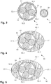
- the Figure 1 shows a cross section through a first embodiment of a cable suitable for the transmission of audio signals according to the invention.
- the cable 10 is particularly suitable for asymmetrical transmission of audio signals. It comprises a core 11 made of an insulating plastic material and four insulated copper strands 12.1, 12.2, 12.3, 12.4 surrounding the core. Their cross-section is 6 mm 2 each.
- the strands are stranded with the core, ie they run without crossing over along a helical line around the core.
- the strands and the core are jointly surrounded by a shield 13, which is made as a braid made of suitable metal, e.g. B. made of tinned copper wire is formed.
- the shield 13 can also comprise a film.
- the entire cable 10 is externally covered by a suitable insulation 14 made of, for. B. plastic such as PVC, PU or PE, which forms the cable sheath.
- One of two diagonally opposite copper strands 12.1, 12.3 is to the positive pole, the other to the negative pole of the connector (z. B. Cinch plug) or to separate plugs (z. B. "banana plug") for the plus and connected to the negative pole.
- the further copper strands 12.2, 12.4, which are also opposite one another and which are arranged between the connected conductors, are not connected with plugs, but rather end in particular where the insulation 14 also ends.
- the shield 13 is connected at one cable end or at both cable ends to the ground pole of the respective connector.
- the plugs have contact and connecting parts made of gold-plated (or otherwise refined) copper and are pressed (forged) onto the stripped copper strands 12.1, 12.3.
- the Figure 2 shows a cross section through a second embodiment of a cable suitable for the transmission of audio signals according to the invention.
- the cable 20 is particularly suitable for the symmetrical transmission of audio signals. It includes a core 21 made of an insulating plastic material and seven insulated copper strands 22.1 ... 22.7 surrounding the core, each with a cross section of 1.5 mm 2 .
- the strands are stranded with the core, ie they run without crossing over along a helical line around the core.
- the strands and the core are jointly surrounded by a sheath 25, this in turn by a shield 23, which is designed as a braid made of tinned copper wire.
- the shield 23 can also comprise a film.
- the entire cable 20 is externally covered by an insulation 24 made of, for. B. plastic such as PVC, PU or PE, which forms the cable sheath.
- Three non-adjacent copper strands 22.1, 22.3 and 22.5 are either connected to the positive, negative or ground poles of the connecting plugs (e.g. XLR plugs) or to separate plugs (e.g. "banana plugs") for the three Poles connected.
- the other copper strands 22.2, 22.4, 22.6, 22.7, which are arranged between the connected conductors, are not connected with plugs, but end in particular where the insulation 24 also ends.
- the shield 23 is connected at one cable end or at both cable ends to the ground pole of the respective plug.
- the plugs have contact and connecting parts made of gold-plated (or otherwise refined) copper and are pressed (forged) onto the stripped copper strands 22.1, 22.3, 22.5.
- the Figure 3 shows a cross section through a third embodiment of a cable combination suitable for the transmission of audio signals according to the invention.
- the combination is particularly suitable for asymmetrical transmission of audio signals. It comprises a signal cable 30 with a core 31 made of an insulating plastic material and four insulated copper strands 32.1, 32.2, 32.3, 32.4 surrounding the core.
- the strands are stranded with the core, ie they run without crossing over along a helical line around the core.
- the strands and the core are jointly surrounded by a shield 33, which is designed as a braid made of tinned copper wire.
- the shield 33 can also comprise a film.
- the entire signal cable 30 is externally covered by an insulation 34 made of plastic, e.g. B. PVC, PU or PE, which forms the cable sheath.
- Two diagonally opposite copper strands 32.1, 32.3 are jointly connected to the positive pole of the connector (e.g. cinch connector) or to a separate connector (e.g. "banana plug") connected for the positive pole.
- the further copper strands 32.2, 32.4, which are also opposite one another and which are arranged between the connected conductors, are not connected with plugs, but rather end in particular where the insulation 34 also ends.
- the shield 33 is connected at one end of the cable to the ground pole of the respective plug, but not at the other end of the cable.
- the cable end with the connected shielding is advantageously plugged in on the signal source side.
- the plugs have contact and connection parts made of gold-plated copper and are pressed (forged) onto the stripped copper strands 32.1, 32.3.
- the cable combination also has an earth cable 36, which is made up of a copper braid 37 and an insulation 38 surrounding it.
- the cross section of the copper braid 37 corresponds approximately to the sum of the cross sections of the copper braids 32.1, 32.3.
- the ground cable 36 is routed separately from the signal cable 30 and connected at both ends to the ground pole of the respective plug or to a separate ground plug.
- the Figure 4 shows a cross section through a fourth embodiment of a cable suitable for the transmission of audio signals according to the invention.
- the cable 40 is particularly suitable for the asymmetrical transmission of audio signals. It comprises a core 41 made of an insulating plastic material and four insulated copper strands 42.1, 42.2, 42.3, 42.4 surrounding the core.
- the strands are stranded with the core, ie they run without crossing over along a helical line around the core.
- the strands and the core are jointly surrounded by a shield 43, which is designed as a braid made of tinned copper wire.
- the shield 43 can also comprise a film.
- the shielded strands 42.1 ... 4 are in an insulation 44 made of, for. B. plastic such as PVC, PU or PE added, which forms the cable sheath.
- a ground conductor 47 which is arranged outside the shielding 43 of the copper strands 42.1... 4, is also received in the insulation 44.
- Two diagonally opposite copper strands 42.1, 42.3 are connected together to the positive pole of the connecting plug (e.g. cinch plug) or to a separate plug (e.g. "banana plug") for the positive pole.
- the other, likewise opposite copper strands 42.2, 42.4, which are located between the connected conductors are arranged, are not connected to plugs, but end in particular where the insulation 44 ends.
- the shielding 43 is connected at one end of the cable to the ground pole of the respective plug, but not at the other end of the cable.
- the cable end with the connected shielding is advantageously plugged in on the signal source side.
- the plugs have contact and connecting parts made of gold-plated (or otherwise refined) copper and are pressed (forged) onto the stripped copper strands 42.1, 42.3.
- the ground conductor 47 is connected at both ends to the ground pole of the respective plug or to a separate ground plug.
- the Figure 5 shows a cross section through a fifth embodiment of a cable suitable for the transmission of audio signals according to the invention. It corresponds in many respects to the fourth embodiment.
- This cable 50 is also particularly suitable for the asymmetrical transmission of audio signals. It comprises a core 51 made of an insulating plastic material and four insulated copper strands 52.1, 52.2, 52.3, 52.4 surrounding the core.
- the strands are stranded with the core, ie they run without crossing over along a helical line around the core.
- the strands and the core are jointly surrounded by a shield 53, which is designed as a braid made of tinned copper wire.
- the shield 53 can also comprise a film.
- Two diagonally opposite copper strands 52.1, 52.3 are jointly connected to the positive pole of the connecting plug (e.g. cinch plug) or to a separate plug (e.g. "banana plug") for the positive pole.
- the further copper strands 52.2, 52.4, which are also opposite one another and which are arranged between the connected conductors, are not connected with plugs, but rather end in particular where the insulation 54 also ends.
- the shield 53 is connected at one end of the cable to the ground pole of the respective plug, but not at the other end of the cable. With Advantageously, that end of the cable with connected shielding is plugged in on the signal source side.
- the plugs have contact and connecting parts made of gold-plated (or otherwise refined) copper and are pressed (forged) onto the stripped copper strands 52.1, 52.3.
- ground conductors 57.1, 57.2 are connected at both ends to the ground pole of the respective plug or to a separate ground plug.
- the Figure 6 shows a sixth embodiment of a cable suitable for the transmission of audio signals according to the invention.
- the cable 60 is particularly suitable for controlling loudspeakers and connects, for example, an (end) amplifier to a loudspeaker. It comprises two subcables 60a, 60b that run in parallel. Each of the subcables contains seven copper strands 62.1a ... 62.7a; 62.1b ... 62.7b with a cross section of 4.0 mm 2 each (other cross sections, in particular in the range 0.5 - 6.0 mm 2, are also conceivable). The strands are surrounded by a sheath 65, this in turn by a shield 63, which is designed as a braid made of tinned copper wire.
- the shield 63 can also comprise a film.
- Each sub-cable 60a, 60b is externally covered by an insulation 64a, 64b made of e.g. B. plastic such as PVC, PU or PE, which forms the partial cable sheath.
- the two partial cables 60a, 60b are twisted with one another and together surrounded by a braid 66.
- Two diametrically opposite copper strands 62.2a, 62.5a; 62.2b, 62.5b of each partial cable 60a, 60b are connected together with the positive pole (partial cable 60a) or with the negative pole (partial cable 60b) of suitable plugs (for example "banana plugs").
- the other copper strands 62.1a, 62.3a, 62.4a, 62.6a, 62.7a; 62.1b, 62.3b, 62.4b, 62.6b, 62.7b, which are arranged between the connected conductors, are not connected with plugs, but in particular end where the insulation 64a, 64b also ends.
- the shield 63 is also not connected to the connectors.
- the plugs have contact and connecting parts made of gold-plated (or otherwise refined) copper and are on the stripped copper strands 62.2a, 62.5a; 62.2b, 62.5b pressed on (forged on).
- a ground conductor that is electrically and / or physically separated from the signal cable can also be used for symmetrical signal transmission.
- the number of conductors and their cross-sections as well as the materials used can easily be adapted within the scope of the invention to the application, namely to the currents to be transmitted and the line length.
- the attachment and contacting of the cables on the connectors or plugs can also be done in different ways, e.g. B. by pressing or forging, soldering, etc. take place.
- the invention provides cables for the transmission of audio signals, in particular analog audio signals, which have a comparatively simple structure and enable good sound quality.
Landscapes
- Communication Cables (AREA)
- Insulated Conductors (AREA)
Description
- Die Erfindung betrifft ein Kabel und die Verwendung eines solchen Kabels für die Übertragung von Tonsignalen, insbesondere von analogen Tonsignalen, wobei das Kabel folgendes umfasst: mindestens zwei Leiter, ein erstes Anschlussstück an einem ersten Ende des Kabels zum Anschliessen des Kabels an ein erstes Gerät und ein zweites Anschlussstück an einem zweiten Ende des Kabels zum Anschliessen des Kabels an ein zweites Gerät. Die Erfindung betrifft weiter die Verwendung eines Kabels für die Übertragung von Tonsignalen, wobei das Kabel folgendes umfasst: mindestens einen Leiter, mindestens eine Abschirmung, welche den mindestens einen Leiter abschirmt, mindestens eine isolierte Masseverbindung, ein erstes Anschlussstück an einem ersten Ende des Kabels zum Anschliessen des Kabels an ein erstes Gerät und ein zweites Anschlussstück an einem zweiten Ende des Kabels zum Anschliessen des Kabels an ein zweites Gerät.
- Im Rahmen der Wiedergabe von Tonsignalen, z. B. im Rahmen der Beschallung von privaten oder geschäftlichen Räumlichkeiten, Konzertsälen u.s.w., werden u. a. analoge Tonsignale mittels elektrischer Signale übertragen. Dazu werden u. a. Niederfrequenzkabel (NF-Kabel) verwendet, die beispielsweise Wiedergabegeräte ("Tonquellen") und Verstärker sowie Geräte zur Klangbeeinflussung verbinden und Lautsprecherkabel, welche beispielsweise Verstärker mit Lautsprechern verbinden. Weitere Kabel mit elektrischen Leitern werden - als Alternative zu Lichtleitern - für die Übertragung von digitalen Tonsignalen eingesetzt.
- Den für die Übertragung von Tonsignalen, insbesondere von analogen Tonsignalen, verwendeten Kabeln kommt eine grosse Bedeutung für die Klangqualität zu. Bei der Verwendung von Kabeln mit einem ungeeigneten Aufbau oder mit zu geringem Querschnitt wird die Klangqualität stark beeinträchtigt.
- Üblicherweise werden für die Übertragung von analogen Tonsignalen abgeschirmte Kabel verwendet, welche mehrere isolierte Litzen umfassen, die von einer Abschirmung umgeben sind. Die Litzen sind jeweils mit Kontakten beider Anschlussstücke (z. B. Steckern oder Buchsen) leitend verbunden. Die Abschirmung ist mit dem Massekontakt mindestens eines der Anschlussstücke leitend verbunden.
- Die
US2012/076342 A1 offenbart ein Kabel aus dem Stand der Technik, welches zur Übertragung von Audiosignalen verwendet wird. - Es hat sich nun gezeigt, dass im Rahmen von herkömmlichen Kabeln mit einem solchen Aufbau aufwändige Massnahmen getroffen werden müssen, um eine zuverlässige Übertragung der Tonsignale zu gewährleisten und damit einen guten Klang zu ermöglichen.
- Aufgabe der Erfindung ist es, Kabel für die Übertragung von Tonsignalen, insbesondere von analogen Tonsignalen, vorzuschlagen, welche einen vergleichsweise einfachen Aufbau aufweisen und eine gute Klangqualität ermöglichen.
- Die Lösung der Aufgabe ist durch die Merkmale des Anspruchs 1 definiert. Gemäss der Erfindung sind mindestens zwei der Leiter weder leitend mit dem ersten Anschlussstück, noch leitend mit dem zweiten Anschlussstück verbunden. Dies bedeutet, dass diese mindestens zwei Leiter auch bei vollständig angeschlossenem Kabel weder mit dem ersten am Kabel angeschlossenen Gerät, noch mit dem zweiten am Kabel angeschlossenen Gerät leitend verbunden ist (Blindleiter).
- Unter dem Begriff "Anschlussstück" wird im Rahmen der vorliegenden Ausführungen jeweils die Gesamtheit der Verbinder verstanden, die ein Kabel an einem seiner Enden aufweist. Es kann sich dabei um einen ein- oder mehrpoligen Stecker oder eine ein- oder mehrpolige Buchse handeln aber auch um mehrere Stecker bzw. Buchsen oder andere Elemente, die es ermöglichen Leiter des Kabels von aussen leitend zu kontaktieren. Das Kabel kann an seinen beiden Enden unterschiedlich beschaltete und/oder ausgebildete Anschlussstücke aufweisen. Die Anschlussstücke können im einfachsten Fall auch einfach durch blanke Draht- oder Litzenenden bzw. verzinnte oder mit einer anderen Metallschicht versehene Draht- oder Litzenenden gebildet sein.
- Es hat sich gezeigt, dass der erfindungsgemässe Aufbau und die erfindungsgemässe Kontaktierung eine überaus gute Übertragung von Tonsignalen, insbesondere von analogen Tonsignalen, ermöglichen und zwar sowohl bei NF-Kabeln als auch bei Lautsprecherkabeln. Dies auch im Vergleich mit Kabeln, deren leitender Querschnitt deutlicher grösser ist als derjenige der erfindungsgemäss konfigurierten Kabel. Da im Rahmen der Erfindung eigentlich vom Kabel bereitgestellter leitender Querschnitt ungenutzt verbleibt, ist diese Feststellung überraschend.
- Im Gegensatz zu üblichen Ansätzen, bei welchem der Materialwahl für die Leiter die meiste Beachtung geschenkt wird, schlägt die Erfindung einen neuartigen Schaltungsaufbau vor.
- Gemäss der Erfindung weist das Kabel mindestens vier Leiter auf, wobei mindestens zwei der mindestens vier Leiter zwei Verbindungen zwischen dem ersten Anschlussstück und dem zweiten Anschlussstück schaffen (z. B. "plus" und "minus" bei einer asymmetrischen Verbindung). Mindestens zwei weitere der mindestens vier Leiter sind zudem weder leitend mit dem ersten Anschlussstück noch leitend mit dem zweiten Anschlussstück verbunden.
- Erfindungsgemäß sind nun die mindestens vier Leiter überkreuzungsfrei im Kabel angeordnet und die mindestens zwei Verbindung schaffenden Leiter sind voneinander durch jeweils mindestens einen der nicht verbundenen Leiter separiert. "Überkreuzungsfrei" bedeutet, dass sich die relative Anordnung der mindestens vier Leiter im Kabelquerschnitt gesehen über die gesamte Kabellänge nicht ändert. Es ist also eine schraubenartige Verdrehung des Leiterpakets möglich, nicht aber eine Änderung der relativen Anordnung, d. h. z. B. der Reihenfolge der Leiter in einer vorgegebenen Drehrichtung. Es hat sich gezeigt, dass die Anordnung der nicht verbundenen Leiter zwischen den verbundenen Leitern der Übertragungsqualität zugute kommt.
- Mit Vorteil sind die mindestens zwei Leiter einzeln isoliert. Dies stellt sicher, dass die Leiter im Kabel durchgehend voneinander isoliert sind. Falls benötigt können in diesem Fall Verbindungen zwischen mehreren der mindestens zwei Leiter im Bereich eines oder beider Anschlussstücke vorhanden sein oder geräteseitig. Anstelle gesonderter Isolationen der mindestens zwei Leiter können die Leiter auch beispielsweise in einem Isolationsmedium eingebettet sein, oder einer der Leiter ist rundum isoliert, während der andere ohne Isolation benachbart zum isolierten Leiter geführt ist.
- Bei einer besonderen Ausführungsform handelt es sich beim Kabel um ein Kabel zur symmetrischen Signalübertragung. Die symmetrische Übertragung von Tonsignalen erfolgt z. B. über mindestens dreiadrige Kabel mit XLR-Steckverbindern. Sie ermöglicht eine störungsfreie Übermittlung von Signalen auch bei längeren Übertragungswegen. Es zeigt sich nun, dass die Verwendung erfindungsgemässer Kabel auch bei der symmetrischen Übertragung von Tonsignalen, insbesondere im Rahmen analoger NF-Kabel, Vorteile für die Übertragungsqualität hat.
- Ein erfindungsgemäss für die symmetrische Signalübertragung verwendbares Kabel umfasst nun mindestens zwei Signalleiter, mindestens einen Masseleiter und mindestens einen Leiter, welcher weder leitend mit dem ersten Anschlussstück noch leitend mit dem zweiten Anschlussstück verbunden ist. Die beiden Signalleiter transportieren das Signal und ein Referenzsignal entgegengesetzter Polarität.
- Bevorzugt umfasst ein erfindungsgemäss für die symmetrische Signalübertragung verwendbares Kabel mindestens zwei Signalleiter, mindestens einen Masseleiter und mindestens drei Leiter, welche weder leitend mit dem ersten Anschlussstück noch leitend mit dem zweiten Anschlussstück verbunden sind. Die beiden Signalleiter transportieren das Signal und ein Referenzsignal entgegengesetzter Polarität. Mit Vorteil sind die Signalleiter, der Masseleiter und die drei nicht verbundenen Leiter allesamt miteinander verdrillt, d. h. gemeinsam verseilt.
- Ferner sind mit Vorteil alle Leiter überkreuzungsfrei im Kabel angeordnet, und die mindestens zwei Signalleiter und der Masseleiter sind voneinander durch jeweils mindestens einen der nicht verbundenen Leiter separiert.
- Mit Vorteil umfasst das Kabel einen Kern aus nichtleitendem Material und diesen Kern kontaktierende Leiter. Der Kern ermöglicht eine definierte Anordnung der ihn umgebenden Leiter und stellt sicher, dass Leiter, die nicht entlang des Umfangs benachbart und nur durch die dazwischenliegende Isolation getrennt sind, einen gewissen Minimalabstand einhalten. Der Kern kann beispielsweise aus Kunststoff, z. B. PVC, PU oder PE, oder auch aus Naturfasern (z. B. Wolle oder Seide) gefertigt sein.
- Der Kern kann auch durch ein leitendes Material gebildet sein, insbesondere durch einen Blindleiter, also einen Leiter, der auch bei vollständig angeschlossenem Kabel weder mit dem ersten am Kabel angeschlossenen Gerät, noch mit dem zweiten am Kabel angeschlossenen Gerät leitend verbunden ist.
- Mit Vorteil umfasst das Kabel eine Abschirmung. Dadurch kann der Einfluss externer Störsignale reduziert werden.
- Die Abschirmung schirmt beim erfindungsgemässen Kabel insbesondere mindestens zwei Leiter ab. Dabei handelt es sich beispielsweise um mindestens einen Blindleiter und mindestens einen Signalleiter.
- Bevorzugt ist die Abschirmung mindestens mit dem ersten Anschlussstück oder mit dem zweiten Anschlussstück leitend verbunden.
- Bei einer vorteilhaften Ausführungsform ist die Abschirmung quellenseitig, d. h. in Richtung der Tonquelle, mit dem entsprechenden Anschlussstück leitend verbunden, nicht jedoch mit dem von der Quelle abgewandten Anschlussstück.
- Bei anderen Ausführungsformen ist die Abschirmung weder mit dem ersten noch mit dem zweiten Anschlussstück leitend verbunden.
- Vorzugsweise umfasst mindestens das erste Anschlussstück oder das zweite Anschlussstück einen Stecker, welcher auf mindestens einen der Leiter aufgepresst ist. Es hat sich gezeigt, dass sich mit einem aufgepressten Stecker hinsichtlich der Übertragungsqualität bessere Ergebnisse erreichen lassen als mit einem verlöteten Stecker, weil ein direkter Kontakt zwischen Leiter und Stecker geschaffen wird. Bevorzugt ist der Stecker aus Kupfer gefertigt und vergoldet, versilbert oder rhodiniert. Alternativ ist der Stecker massiv aus Silber oder Gold gefertigt.
- Alternativ lassen sich die Leiter auch beispielsweise durch eine Lötverbindung mit den entsprechenden Kontakten des ersten bzw. des zweiten Anschlussstücks verbinden.
- Bevorzugt ist mindestens einer der Leiter durch eine isolierte Kupferlitze gebildet. Besonders bevorzugt sind alle Leiter durch isolierte Kupferlitzen gebildet. Aufgrund des Skin-Effekts ergibt sich durch die Verwendung von Litzen zur Übertragung von Wechselsignalen ein höherer effektiv leitender Querschnitt als bei der Verwendung von Drähten mit demselben Gesamtquerschnitt. Mittels Litzen können zudem flexible und langlebige Kabel hergestellt werden. Die Übertragungsqualität kann optimiert werden, wenn qualitativ hochwertiges sauerstofffreies Kupfer ("oxygen-free copper", OFC) verwendet wird. Dies ist jedoch entgegen der herrschenden Meinung nicht zwingend. Auch bei der Verwendung handelsüblichen Kupfers, wie es z. B. für Kabel zur Leitung von Strom im Haushaltsnetz eingesetzt wird, ergeben sich im Rahmen der erfindungsgemässen Verwendung bereits sehr gute Übertragungswerte.
- Für die Leiter können auch andere Materialien wie z. B. Silber verwendet werden. Für die Blindleiter, d. h. die Leiter, die auch bei vollständig angeschlossenem Kabel weder mit dem ersten am Kabel angeschlossenen Gerät, noch mit dem zweiten am Kabel angeschlossenen Gerät leitend verbunden sind, kann beispielsweise auch Aluminium als Leitermaterial eingesetzt werden.
- Bei einer bevorzugten Ausführungsform ist ein erster der mindestens zwei Leiter als Draht und ein zweiter der mindestens zwei Leiter als Litze ausgeführt. Versuche haben gezeigt, dass durch diese Kombination die Klangqualität der erfindungsgemässen Kabel weiter verbessert werden kann.
- Auch bei der Verwendung von Drähten werden bevorzugt Leiter verwendet, die direkt mit einer Isolation versehen sind. Sie lassen sich einfach verarbeiten (verseilen) und stellen sicher, dass keine Kurzschlüsse erfolgen. Alternativ werden die Leiter beispielsweise in einem gemeinsamen Isolationsmedium eingebettet oder durch spezielle Distanzhalter räumlich voneinander separiert.
- Bei einer bevorzugten Ausführungsform ist der weder leitend mit dem ersten Anschlussstück noch leitend mit dem zweiten Anschlussstück verbundene Leiter an mindestens einem Ort entlang seiner Länge unterbrochen. Es hat sich gezeigt, dass dadurch - je nach Anwendung - eine weitere Verbesserung der Übertragungsqualität erzielbar ist.
- Es können mehrere nicht verbundene Leiter vorhanden sein, die mindestens einmal unterbrochen sind. Der Unterbruch muss sich dabei nicht an derselben Stelle im Kabel befinden. Durch die Wahl der Anzahl der Unterbrüche, deren Länge und deren gegenseitige Anordnung lässt sich die Übertragungscharakteristik des Kabels beeinflussen.
- Bei einer bevorzugten Ausführungsform der Erfindung, bei welcher das Kabel insbesondere zur Signalversorgung von Lautsprechern dient, umfasst das Kabel ein erstes Teilkabel und ein zweites Teilkabel, welche beide von einer gemeinsamen Umhüllung aufgenommen sind. Dabei umfassen das erste Teilkabel und das zweite Teilkabel je mindestens zwei Leiter, wobei mindestens einer der zwei Leiter weder leitend mit dem ersten Anschlussstück noch leitend mit dem zweiten Anschlussstück verbunden ist. Jedes Teilkabel umfasst also mindestens einen Blindleiter.
- Mit Vorteil umfassen das erste Teilkabel und das zweite Teilkabel dabei je eine eigene Abschirmung, welche die mindestens zwei Leiter des jeweiligen Teilkabels abschirmt. Die gegenseitige Beeinflussung der beiden Teilkabel wird dadurch minimiert.
- Ebenfalls bevorzugt sind das erste Teilkabel und das zweite Teilkabel miteinander verdrillt. Dadurch ergeben sich insbesondere verbesserte mechanische Eigenschaften des aus zwei Teilkabel aufgebauten Kabels.
- Die zwei Teilkabel sind insbesondere derart mit dem ersten und dem zweiten Anschlussstück verbunden, dass eine erste Polarität (z. B. das eigentliche Tonsignal) ausschliesslich durch das erste Teilkabel und eine zweite Polarität (z. B. die Masse) ausschliesslich durch das zweite Teilkabel geführt werden. Eine gegenseitige Beeinflussung der Signale der beiden Polaritäten wird dadurch minimiert.
- In einem alternativen Beispiel, das nicht unter den Gegenstand der Ansprüche fällt, kann ein Kabel Verwendung finden, welches folgendes umfasst:
- a) mindestens einen Leiter;
- b) mindestens eine Abschirmung, welche den mindestens einen Leiter abschirmt;
- c) mindestens eine isolierte Masseverbindung;
- d) ein erstes Anschlussstück an einem ersten Ende des Kabels zum Anschliessen des Kabels an ein erstes Gerät;
- e) ein zweites Anschlussstück an einem zweiten Ende des Kabels zum Anschliessen des Kabels an ein zweites Gerät;
wobei - f) die Abschirmung höchstens mit einem der beiden Anschlussstücke leitend verbunden ist; und
- g) die Masseverbindung ausserhalb der Abschirmung geführt ist.
- Die Masseverbindung erfolgt somit nicht über die Abschirmung der abgeschirmten Kabel, sondern über die ausserhalb der Abschirmung verlaufende Masseverbindung. Besonders geeignet ist diese Konfiguration für NF-Gerätekabel. Bei der Verbindung einer Signalquelle mit einem Verstärker ist die Abschirmung bevorzugt zwar mit der Signalquelle verbunden, nicht jedoch mit dem Verstärker. Es hat sich gezeigt, dass auch durch diese Massnahmen die Übertragungsqualität für Tonsignale deutlich gesteigert werden kann.
- Auch hier wird im Gegensatz zu üblichen Ansätzen nicht ein neues oder besonderes Material für die Leiter gewählt, sondern es wird ein anderer Schaltungsaufbau verwendet.
- Bei einer bevorzugten Ausführungsform ist die Masseverbindung in einer Isolation des Kabels geführt. Das Kabel erscheint zwar als Einheit, in funktioneller Hinsicht handelt es sich aber eigentlich um zwei Kabel, nämlich das abgeschirmte Signalkabel und das parallel dazu verlaufende Massekabel, welches ausserhalb der Abschirmung des Signalkabels verläuft. Die gemeinsame Isolation hat die Zusatzaufgabe, die beiden Kabel in einem bestimmten Abstand zu führen und das Handling zu vereinfachen.
- Alternativ dazu handelt es sich bei der Masseverbindung um ein komplett gesondertes Kabel, welches erst an seinen Enden zusammen mit dem Signalkabel (welches den mindestens einen Leiter umfasst) in die entsprechenden Anschlussstücke geführt wird.
- Im Zusammenhang mit der gesonderten Masseverbindung kann ein Adapterkabel eingesetzt werden. Dieses umfasst
- ein erstes Zwischenstück, welches sich an ein erstes Gerät anschliessen lässt und an welches ein erstes Anschlussstück eines Kabels anschliessbar ist;
- ein zweites Zwischenstück, welches sich an ein zweites Gerät anschliessen lässt und an welches ein zweites Anschlussstück des Kabels anschliessbar ist;
- eine isolierte Masseverbindung, welche einen Massekontakt des ersten Zwischenstücks mit einem Massekontakt des zweiten Zwischenstücks verbindet;
- Bevorzugt ist bei einem der Zwischenstücke die Masseverbindung unterbrochen, beim anderen Zwischenstück aber durchgeführt. Das Zwischenstück mit unterbrochener Masseverbindung wird dann mit Vorteil am signalquellenfernen Gerät eingesteckt. Zusammen mit dem Adapterkabel kann ein übliches (und ggf. bereits vorhandenes), insbesondere abgeschirmtes, Kabel eingesetzt werden, welches weiterhin als Signalleiter dient.
- Aus der nachfolgenden Detailbeschreibung und der Gesamtheit der Patentansprüche ergeben sich weitere vorteilhafte Ausführungsformen und Merkmalskombinationen der Erfindung.
- Die zur Erläuterung des Ausführungsbeispiels verwendeten Zeichnungen zeigen:
- Fig. 1
- Eine erste Ausführungsform eines zur erfindungsgemässen Übertragung von Tonsignalen geeigneten Kabels;
- Fig. 2
- eine zweite Ausführungsform eines zur erfindungsgemässen Übertragung von Tonsignalen geeigneten Kabels;
- Fig. 3
- eine dritte Ausführungsform einer zur erfindungsgemässen Übertragung von Tonsignalen geeigneten Kabelkombination
- Fig. 4
- eine vierte Ausführungsform eines zur erfindungsgemässen Übertragung von Tonsignalen geeigneten Kabels;
- Fig. 5
- eine fünfte Ausführungsform eines zur erfindungsgemässen Übertragung von Tonsignalen geeigneten Kabels; und
- Fig. 6
- eine sechste Ausführungsform eines zur erfindungsgemässen Übertragung von Tonsignalen geeigneten Kabels.
- Grundsätzlich sind in den Figuren gleiche Teile mit gleichen Bezugszeichen versehen.
- Die
Figur 1 zeigt einen Querschnitt durch eine erste Ausführungsform eines zur erfindungsgemässen Übertragung von Tonsignalen geeigneten Kabels. Das Kabel 10 ist insbesondere zur asymmetrischen Übertragungen von Tonsignalen geeignet. Es umfasst einen Kern 11 aus einem isolierenden Kunststoffmaterial und vier den Kern umgebende isolierte Kupferlitzen 12.1, 12.2, 12.3, 12.4. Deren Querschnitt beträgt je 6 mm2. Die Litzen sind mit dem Kern verseilt, d. h. sie verlaufen überkreuzungsfrei entlang einer Schraubenlinie um den Kern. Die Litzen und der Kern sind gemeinsam umgeben von einer Abschirmung 13, welche als Geflecht aus geeignetem Metall, z. B. aus verzinntem Kupferdraht, ausgebildet ist. Alternativ oder zusätzlich kann die Abschirmung 13 auch eine Folie umfassen. Das gesamte Kabel 10 wird aussen von einer geeigneten Isolation 14 aus z. B. Kunststoff wie PVC, PU oder PE umgeben, welche den Kabelmantel bildet. - Eine von zwei einander diagonal gegenüberliegenden Kupferlitzen 12.1, 12.3 ist an die Pluspole, die andere an die Minuspole der Verbindungsstecker (z. B. Cinch-Stecker) bzw. an gesonderte Stecker (z. B. "Bananenstecker") für den Plus- und den Minuspol angeschlossen. Die weiteren, einander ebenfalls gegenüberliegenden Kupferlitzen 12.2, 12.4, welche zwischen den verbundenen Leitern angeordnet sind, sind nicht mit Steckern verbunden, sondern enden insbesondere dort, wo auch die Isolation 14 endet. Die Abschirmung 13 ist an einem Kabelende oder an beiden Kabelenden mit dem Massepol des jeweiligen Steckers verbunden. Die Stecker weisen Kontakt- und Verbindungsteile aus vergoldetem (oder andersartig veredelten) Kupfer auf und sind auf die abisolierten Kupferlitzen 12.1, 12.3 aufgepresst (aufgeschmiedet).
- Die
Figur 2 zeigt einen Querschnitt durch eine zweite Ausführungsform eines zur erfindungsgemässen Übertragung von Tonsignalen geeigneten Kabels. Das Kabel 20 ist insbesondere zur symmetrischen Übertragungen von Tonsignalen geeignet. Es umfasst einen Kern 21 aus einem isolierenden Kunststoffmaterial und sieben den Kern umgebende isolierte Kupferlitzen 22.1...22.7 mit einem Querschnitt von je 1.5 mm2. Die Litzen sind mit dem Kern verseilt, d. h. sie verlaufen überkreuzungsfrei entlang einer Schraubenlinie um den Kern. Die Litzen und der Kern sind gemeinsam umgeben von einer Hülle 25, diese wiederum von einer Abschirmung 23, welche als Geflecht aus verzinntem Kupferdraht ausgebildet ist. Alternativ oder zusätzlich kann die Abschirmung 23 auch eine Folie umfassen. Das gesamte Kabel 20 wird aussen von einer Isolation 24 aus z. B. Kunststoff wie PVC, PU oder PE umgeben, welche den Kabelmantel bildet. - Drei jeweils nicht benachbarte Kupferlitzen 22.1, 22.3 und 22.5 sind je entweder an die Pluspole, die Minuspole oder die Massepole der Verbindungsstecker (z. B. XLR-Stecker) bzw. an gesonderte Stecker (z. B. "Bananenstecker") für die drei Pole angeschlossen. Die weiteren, Kupferlitzen 22.2, 22.4, 22.6, 22.7, welche zwischen den verbundenen Leitern angeordnet sind, sind nicht mit Steckern verbunden, sondern enden insbesondere dort, wo auch die Isolation 24 endet. Die Abschirmung 23 ist an einem Kabelende oder an beiden Kabelenden mit dem Massepol des jeweiligen Steckers verbunden. Die Stecker weisen Kontakt- und Verbindungsteile aus vergoldetem (oder andersartig veredeltem) Kupfer auf und sind auf die abisolierten Kupferlitzen 22.1, 22.3, 22.5 aufgepresst (aufgeschmiedet).
- Die
Figur 3 zeigt einen Querschnitt durch eine dritte Ausführungsform einer zur erfindungsgemässen Übertragung von Tonsignalen geeigneten Kabelkombination. Die Kombination ist insbesondere zur asymmetrischen Übertragung von Tonsignalen geeignet. Sie umfasst ein Signalkabel 30 mit einem Kern 31 aus einem isolierenden Kunststoffmaterial und vier den Kern umgebende isolierte Kupferlitzen 32.1, 32.2, 32.3, 32.4. Die Litzen sind mit dem Kern verseilt, d. h. sie verlaufen überkreuzungsfrei entlang einer Schraubenlinie um den Kern. Die Litzen und der Kern sind gemeinsam umgeben von einer Abschirmung 33, welche als Geflecht aus verzinntem Kupferdraht ausgebildet ist. Alternativ oder zusätzlich kann die Abschirmung 33 auch eine Folie umfassen. Das gesamte Signalkabel 30 wird aussen von einer Isolation 34 aus Kunststoff, z. B. PVC, PU oder PE, umgeben, welche den Kabelmantel bildet. - Zwei einander diagonal gegenüberliegende Kupferlitzen 32.1, 32.3 sind gemeinsam an den Pluspol der Verbindungsstecker (z. B. Cinch-Stecker) bzw. an einen gesonderten Stecker (z. B. "Bananenstecker") für den Pluspol angeschlossen. Die weiteren, einander ebenfalls gegenüberliegenden Kupferlitzen 32.2, 32.4, welche zwischen den verbundenen Leitern angeordnet sind, sind nicht mit Steckern verbunden, sondern enden insbesondere dort, wo auch die Isolation 34 endet. Die Abschirmung 33 ist an einem Kabelende mit dem Massepol des jeweiligen Steckers verbunden, nicht jedoch am anderen Kabelende. Mit Vorteil wird dasjenige Kabelende mit verbundener Abschirmung signalquellenseitig eingesteckt. Die Stecker weisen Kontakt- und Verbindungsteile aus vergoldetem Kupfer auf und sind auf die abisolierten Kupferlitzen 32.1, 32.3 aufgepresst (aufgeschmiedet).
- Die Kabelkombination weist zusätzlich ein Massekabel 36 auf, welches aus einer Kupferlitze 37 und einer diese umgebenden Isolation 38 aufgebaut ist. Der Querschnitt der Kupferlitze 37 entspricht ungefähr der Summe der Querschnitte der Kupferlitzen 32.1, 32.3. Das Massekabel 36 ist getrennt vom Signalkabel 30 geführt und an beiden Enden mit dem Massepol des jeweiligen Steckers bzw. mit einem gesonderten Massestecker verbunden.
- Die
Figur 4 zeigt einen Querschnitt durch eine vierte Ausführungsform eines zur erfindungsgemässen Übertragung von Tonsignalen geeigneten Kabels. Das Kabel 40 ist insbesondere zur asymmetrischen Übertragung von Tonsignalen geeignet. Es umfasst einen Kern 41 aus einem isolierenden Kunststoffmaterial und vier den Kern umgebende isolierte Kupferlitzen 42.1, 42.2, 42.3, 42.4. Die Litzen sind mit dem Kern verseilt, d. h. sie verlaufen überkreuzungsfrei entlang einer Schraubenlinie um den Kern. Die Litzen und der Kern sind gemeinsam umgeben von einer Abschirmung 43, welche als Geflecht aus verzinntem Kupferdraht ausgebildet ist. Alternativ oder zusätzlich kann die Abschirmung 43 auch eine Folie umfassen. Die abgeschirmten Litzen 42.1...4 sind in einer Isolation 44 aus z. B. Kunststoff wie PVC, PU oder PE aufgenommen, welche den Kabelmantel bildet. Weiter in der Isolation 44 aufgenommen ist ein Masseleiter 47, der ausserhalb der Abschirmung 43 der Kupferlitzen 42.1...4 angeordnet ist. - Zwei einander diagonal gegenüberliegende Kupferlitzen 42.1, 42.3 sind gemeinsam an den Pluspol der Verbindungsstecker (z. B. Cinch-Stecker) bzw. an einen gesonderten Stecker (z. B. "Bananenstecker") für den Pluspol angeschlossen. Die weiteren, einander ebenfalls gegenüberliegenden Kupferlitzen 42.2, 42.4, welche zwischen den verbundenen Leitern angeordnet sind, sind nicht mit Steckern verbunden, sondern enden insbesondere dort, wo auch die Isolation 44 endet. Die Abschirmung 43 ist an einem Kabelende mit dem Massepol des jeweiligen Steckers verbunden, nicht jedoch am anderen Kabelende. Mit Vorteil wird dasjenige Kabelende mit verbundener Abschirmung signalquellenseitig eingesteckt. Die Stecker weisen Kontakt- und Verbindungsteile aus vergoldetem (oder andersartig veredeltem) Kupfer auf und sind auf die abisolierten Kupferlitzen 42.1, 42.3 aufgepresst (aufgeschmiedet).
- Der Masseleiter 47 ist an beiden Enden mit dem Massepol des jeweiligen Steckers bzw. mit einem gesonderten Massestecker verbunden.
- Die
Figur 5 zeigt einen Querschnitt durch eine fünfte Ausführungsform eines zur erfindungsgemässen Übertragung von Tonsignalen geeigneten Kabels. Sie entspricht in vielerlei Hinsicht der vierten Ausführungsform. Auch dieses Kabel 50 ist insbesondere zur asymmetrischen Übertragung von Tonsignalen geeignet. Es umfasst einen Kern 51 aus einem isolierenden Kunststoffmaterial und vier den Kern umgebende isolierte Kupferlitzen 52.1, 52.2, 52.3, 52.4. Die Litzen sind mit dem Kern verseilt, d. h. sie verlaufen überkreuzungsfrei entlang einer Schraubenlinie um den Kern. Die Litzen und der Kern sind gemeinsam umgeben von einer Abschirmung 53, welche als Geflecht aus verzinntem Kupferdraht ausgebildet ist. Alternativ oder zusätzlich kann die Abschirmung 53 auch eine Folie umfassen. Die abgeschirmten Litzen 52.1...4 sind in einer Isolation 54 aus z. B. Kunststoff wie PVC, PU oder PE aufgenommen, welche den Kabelmantel bildet. Weiter in der Isolation 54 aufgenommen sind zwei Masseleiter 57.1, 57.2, die einander gegenüberliegend ausserhalb der Abschirmung 53 der Kupferlitzen 52.1...4 angeordnet sind. - Zwei einander diagonal gegenüberliegende Kupferlitzen 52.1, 52.3 sind gemeinsam an den Pluspol der Verbindungsstecker (z. B. Cinch-Stecker) bzw. an einen gesonderten Stecker (z. B. "Bananenstecker") für den Pluspol angeschlossen. Die weiteren, einander ebenfalls gegenüberliegenden Kupferlitzen 52.2, 52.4, welche zwischen den verbundenen Leitern angeordnet sind, sind nicht mit Steckern verbunden, sondern enden insbesondere dort, wo auch die Isolation 54 endet. Die Abschirmung 53 ist an einem Kabelende mit dem Massepol des jeweiligen Steckers verbunden, nicht jedoch am anderen Kabelende. Mit Vorteil wird dasjenige Kabelende mit verbundener Abschirmung signalquellenseitig eingesteckt. Die Stecker weisen Kontakt- und Verbindungsteile aus vergoldetem (oder andersartig veredeltem) Kupfer auf und sind auf die abisolierten Kupferlitzen 52.1, 52.3 aufgepresst (aufgeschmiedet).
- Die Masseleiter 57.1, 57.2 sind an beiden Enden mit dem Massepol des jeweiligen Steckers bzw. mit einem gesonderten Massestecker verbunden.
- Die
Figur 6 zeigt eine sechste Ausführungsform eines zur erfindungsgemässen Übertragung von Tonsignalen geeigneten Kabels. Das Kabel 60 ist insbesondere zur Ansteuerung von Lautsprechern geeignet und verbindet beispielsweise einen (End-) Verstärker mit einem Lautsprecher. Es umfasst zwei parallel geführte Teilkabel 60a, 60b. Jedes der Teilkabel beinhaltet sieben Kupferlitzen 62.1a...62.7a; 62.1b...62.7b mit einem Querschnitt von je 4.0 mm2 (andere Querschnitte, insbesondere im Bereich 0.5 - 6.0 mm2 sind ebenfalls denkbar). Die Litzen sind umgeben von einer Hülle 65, diese wiederum von einer Abschirmung 63, welche als Geflecht aus verzinntem Kupferdraht ausgebildet ist. Alternativ oder zusätzlich kann die Abschirmung 63 auch eine Folie umfassen. Jedes Teilkabel 60a, 60b ist aussen von einer Isolation 64a, 64b aus z. B. Kunststoff wie PVC, PU oder PE umgeben, welche den Teilkabelmantel bildet. - Die beiden Teilkabel 60a, 60b sind miteinander verdrillt und gemeinsam von einem Geflecht 66 umgeben.
- Zwei einander diametral gegenüberliegende Kupferlitzen 62.2a, 62.5a; 62.2b, 62.5b jedes Teilkabels 60a, 60b sind gemeinsam mit dem Pluspol (Teilkabel 60a) bzw. mit dem Minuspol (Teilkabel 60b) geeigneter Stecker (z. B. "Bananenstecker") verbunden. Die weiteren Kupferlitzen 62.1a, 62.3a, 62.4a, 62.6a, 62.7a; 62.1b, 62.3b, 62.4b, 62.6b, 62.7b, welche zwischen den verbundenen Leitern angeordnet sind, sind nicht mit Steckern verbunden, sondern enden insbesondere dort, wo auch die Isolation 64a, 64b endet. Die Abschirmung 63 ist ebenfalls nicht mit den Steckern verbunden. Die Stecker weisen Kontakt- und Verbindungsteile aus vergoldetem (oder andersartig veredeltem) Kupfer auf und sind auf die abisolierten Kupferlitzen 62.2a, 62.5a; 62.2b, 62.5b aufgepresst (aufgeschmiedet).
- Die Erfindung ist nicht auf die dargestellten Ausführungsbeispiele beschränkt. So lässt sich ein vom Signalkabel elektrisch und/oder physisch getrennter Masseleiter auch bei der symmetrischen Signalübertragung nutzen. Auch die Anzahl der Leiter und deren Querschnitte sowie die verwendeten Materialien lassen sich im Rahmen der Erfindung ohne weiteres an die Anwendung, namentlich an die zu übertragenden Ströme und die Leitungslänge, anpassen. Die Anbringung und Kontaktierung der Kabel an den Anschlussstücken bzw. Steckern kann ebenfalls auf unterschiedliche Weise, z. B. durch Aufpressen oder Aufschmieden, Verlöten u.s.w. erfolgen.
- Zusammenfassend ist festzustellen, dass die Erfindung Kabel für die Übertragung von Tonsignalen, insbesondere von analogen Tonsignalen, zur Verfügung stellt, welche einen vergleichsweise einfachen Aufbau aufweisen und eine gute Klangqualität ermöglichen.
Claims (12)
- Verwendung eines Kabels (10, 20, 30, 40, 50, 60) für die Übertragung von Tonsignalen, insbesondere von analogen Tonsignalen, wobei das Kabel folgendes umfasst:a) mindestens vier Leiter (12.1, 12.2, 12.3, 12.4);b) ein erstes Anschlussstück an einem ersten Ende des Kabels zum Anschliessen des Kabels an ein erstes Gerät;c) ein zweites Anschlussstück an einem zweiten Ende des Kabels zum Anschliessen des Kabels an ein zweites Gerät;d) eine Abschirmung (13, 23, 33, 43, 53, 63), die die mindestens vier Leiter abschirmt;
dadurch gekennzeichnet, dasse) mindestens zwei der mindestens vier Leiter zwei Verbindungen zwischen dem ersten Anschlussstück und dem zweiten Anschlussstück schaffen, und mindestens zwei weitere der mindestens vier Leiter weder leitend mit dem ersten Anschlussstück noch leitend mit dem zweiten Anschlussstück verbunden sind, wobei die mindestens vier Leiter überkreuzungsfrei im Kabel angeordnet sind und die mindestens zwei Verbindung schaffenden Leiter voneinander jeweils durch mindestens einen der nicht verbundenen Leiter separiert sind. - Verwendung nach Anspruch 1, dadurch gekennzeichnet, dass die mindestens vier Leiter (12.1, 12.2, 12.3, 12.4) einzeln isoliert sind.
- Verwendung nach einem der Ansprüche 1 bis 2, dadurch gekennzeichnet, dass ein erster der mindestens vier Leiter (12.1, 12.2, 12.3, 12.4) als Draht und ein zweiter der mindestens vier Leiter als Litze ausgeführt ist.
- Verwendung nach einem der Ansprüche 1 bis 3, dadurch gekennzeichnet, dass das Kabel (60) ein erstes Teilkabel (60a) und ein zweites Teilkabel (60b) umfasst, welche beide von einer gemeinsamen Umhüllung (65) aufgenommen sind, wobei das erste Teilkabel und das zweite Teilkabel je mindestens zwei Leiter (62.1a...62.7a; 62.1b...62.7b) umfassen, wobei mindestens einer der zwei Leiter weder leitend mit dem ersten Anschlussstück noch leitend mit dem zweiten Anschlussstück verbunden ist.
- Verwendung nach Anspruch 4, dadurch gekennzeichnet, dass das erste Teilkabel (60a) und das zweite Teilkabel (60b) je eine eigene Abschirmung (63a, 63b) umfassen, welche die mindestens zwei Leiter (62.1a...62.7a; 62.1b...62.7b) abschirmt.
- Verwendung nach einem der Ansprüche 1 bis 5, dadurch gekennzeichnet, dass es sich beim Kabel um ein Kabel zur symmetrischen Signalübertragung handelt, wobei das Kabel mindestens zwei Signalleiter, mindestens einen Masseleiter und mindestens drei Leiter umfasst, welche weder leitend mit dem ersten Anschlussstück noch leitend mit dem zweiten Anschlussstück verbunden sind.
- Verwendung nach Anspruch 6, dadurch gekennzeichnet, dass alle Leiter überkreuzungsfrei im Kabel angeordnet sind und dass die mindestens zwei Signalleiter und der Masseleiter voneinander durch jeweils mindestens einen der nicht verbundenen Leiter separiert sind.
- Verwendung nach einem der Ansprüche 1 bis 7, dadurch gekennzeichnet, dass die Abschirmung (13, 23, 33, 43, 53) mindestens mit dem ersten Anschlussstück oder mit dem zweiten Anschlussstück leitend verbunden ist.
- Verwendung nach einem der Ansprüche 1 bis 8, dadurch gekennzeichnet, dass die mindestens zwei weder leitend mit dem ersten Anschlussstück, noch leitend mit dem zweiten Anschlussstück verbundene Leiter (12.2, 12.4) an mindestens einem Ort entlang seiner Länge unterbrochen ist.
- Verwendung nach Anspruch 9, dadurch gekennzeichnet, dass die mindestens zwei nicht verbundenen Leiter (12.2, 12.4) an unterschiedlichen Orten entlang ihrer Länge unterbrochen sind.
- Verwendung nach einem der Ansprüche 1 bis 10, wobei das Kabel (30, 40, 50) folgendes umfasst:a) mindestens eine isolierte Masseverbindung (37, 47, 57.1, 57.2);b) ein erstes Anschlussstück an einem ersten Ende des Kabels zum Anschliessen des Kabels an ein erstes Gerät;c) ein zweites Anschlussstück an einem zweiten Ende des Kabels zum Anschliessen des Kabels an ein zweites Gerät;
wobeid) die Abschirmung (33, 43, 53) höchstens mit einem der beiden Anschlussstücke leitend verbunden ist; unde) die Masseverbindung ausserhalb der Abschirmung geführt ist. - Verwendung gemäss Anspruch 11, dadurch gekennzeichnet, dass die Masseverbindung (47, 57.1, 57.2) in einer Isolation (44, 54) des Kabels geführt ist.
Applications Claiming Priority (2)
| Application Number | Priority Date | Filing Date | Title |
|---|---|---|---|
| CH01244/13A CH708283A1 (de) | 2013-07-11 | 2013-07-11 | Verwendung eines Kabels für die Übertragung von Tonsignalen. |
| PCT/CH2014/000100 WO2015003282A1 (de) | 2013-07-11 | 2014-07-10 | Verwendung eines kabels für die übertragung von tonsignalen |
Publications (2)
| Publication Number | Publication Date |
|---|---|
| EP3020102A1 EP3020102A1 (de) | 2016-05-18 |
| EP3020102B1 true EP3020102B1 (de) | 2021-09-29 |
Family
ID=51224643
Family Applications (1)
| Application Number | Title | Priority Date | Filing Date |
|---|---|---|---|
| EP14742453.5A Active EP3020102B1 (de) | 2013-07-11 | 2014-07-10 | Verwendung eines kabels für die übertragung von tonsignalen |
Country Status (6)
| Country | Link |
|---|---|
| US (1) | US20160172079A1 (de) |
| EP (1) | EP3020102B1 (de) |
| JP (1) | JP2016528679A (de) |
| CN (1) | CN105612669A (de) |
| CH (1) | CH708283A1 (de) |
| WO (1) | WO2015003282A1 (de) |
Families Citing this family (7)
| Publication number | Priority date | Publication date | Assignee | Title |
|---|---|---|---|---|
| US10637196B2 (en) | 2015-11-11 | 2020-04-28 | Bel Fuse (Macao Commercial Offshore) Limited | Modular jack contact assembly having controlled capacitive coupling positioned within a jack housing |
| US10504647B2 (en) * | 2017-04-03 | 2019-12-10 | Bel Fuse (Macao Commercial Off | Magnetic transformer having increased bandwidth for high speed data communications |
| US10530106B2 (en) | 2018-01-31 | 2020-01-07 | Bel Fuse (Macao Commercial Offshore) Limited | Modular plug connector with multilayer PCB for very high speed applications |
| JP2020202058A (ja) * | 2019-06-07 | 2020-12-17 | 有限会社フリーザトーン | ケーブル |
| CH718045B1 (de) * | 2020-11-11 | 2023-08-15 | Pia Linda Rohrer | Kabel für die Übertragung von Tonsignalen. |
| DE102021201644A1 (de) * | 2021-02-22 | 2022-08-25 | Valeo Siemens Eautomotive Germany Gmbh | Kabelverbindung mit verbesserter elektromagnetischer Schirmung |
| DE202021106151U1 (de) | 2021-11-10 | 2021-11-26 | Christian Rohrer | Kabel für die Übertragung von Tonsignalen |
Family Cites Families (15)
| Publication number | Priority date | Publication date | Assignee | Title |
|---|---|---|---|---|
| DE585870C (de) * | 1927-06-09 | 1933-10-13 | Otto Paetsch | Dehn- und stauchbares Mehrleiter-Starkstromkabel |
| CA996645A (en) * | 1974-05-03 | 1976-09-07 | Canada Wire And Cable Limited | Power cable having an extensible ground check conductor |
| US5033091A (en) * | 1989-10-12 | 1991-07-16 | Bond Matthew R | Cable interconnection for audio component system |
| US5313020A (en) * | 1992-05-29 | 1994-05-17 | Western Atlas International, Inc. | Electrical cable |
| US5548082A (en) * | 1994-11-22 | 1996-08-20 | Palmer; Donald E. | Passive signal shielding structure for short-wire cable |
| US5880402A (en) * | 1996-07-22 | 1999-03-09 | Nugent; Steven Floyd | High fidelity audio interconnect cable |
| WO1999019886A1 (en) * | 1997-10-16 | 1999-04-22 | Tara Labs, Inc. | Isolated and floating shielded cable system |
| US6249913B1 (en) * | 1998-10-09 | 2001-06-19 | General Dynamics Ots (Aerospace), Inc. | Aircraft data management system |
| CH694714A5 (de) * | 2000-03-29 | 2005-06-15 | Kaspar Kramis | Symmetrisches oder pseudosymmentrisches Audio-Kleinsignalkabel. |
| US6800810B1 (en) * | 2002-09-03 | 2004-10-05 | William Jody Page | Snake for musical instrument wiring |
| US20100104126A1 (en) * | 2008-10-24 | 2010-04-29 | Andrea Martina Greene | Tangle resistant audio cord and earphones |
| US7804029B1 (en) * | 2008-12-05 | 2010-09-28 | The United States Of America As Represented By The United States Department Of Energy | Electromagnetic wrap |
| WO2010136062A1 (en) * | 2009-05-27 | 2010-12-02 | Prysmian S.P.A. | Electric cable with strain sensor and monitoring system and method for detecting strain in at least one electric cable |
| US8467560B2 (en) * | 2010-09-28 | 2013-06-18 | Apple Inc. | Cables with intertwined strain relief and bifurcation structures |
| US20140010400A1 (en) * | 2012-06-20 | 2014-01-09 | Timothy A. Morris | Magnetic coupling mechanism for earphone wires |
-
2013
- 2013-07-11 CH CH01244/13A patent/CH708283A1/de not_active Application Discontinuation
-
2014
- 2014-07-10 EP EP14742453.5A patent/EP3020102B1/de active Active
- 2014-07-10 JP JP2016524643A patent/JP2016528679A/ja active Pending
- 2014-07-10 US US14/903,967 patent/US20160172079A1/en not_active Abandoned
- 2014-07-10 WO PCT/CH2014/000100 patent/WO2015003282A1/de not_active Ceased
- 2014-07-10 CN CN201480039682.5A patent/CN105612669A/zh active Pending
Also Published As
| Publication number | Publication date |
|---|---|
| JP2016528679A (ja) | 2016-09-15 |
| US20160172079A1 (en) | 2016-06-16 |
| CN105612669A (zh) | 2016-05-25 |
| CH708283A1 (de) | 2015-01-15 |
| WO2015003282A1 (de) | 2015-01-15 |
| EP3020102A1 (de) | 2016-05-18 |
Similar Documents
| Publication | Publication Date | Title |
|---|---|---|
| EP3020102B1 (de) | Verwendung eines kabels für die übertragung von tonsignalen | |
| EP3251173B1 (de) | Steckverbinderanordnung mit hülsenteil | |
| EP3224838B1 (de) | Kabel mit verseilten aderpaaren | |
| DE102011106727B3 (de) | Stecker für feuchtigkeitsgeschützte elektrische Steckverbindung | |
| DE60126369T2 (de) | Steckverbinder mit Kontakten die in einem angepassten isolierenden Gehäuse montiert sind | |
| DE3337432A1 (de) | Signalkabel | |
| DE202015000750U1 (de) | Steckverbinderanordnung mit Kompensationshülse | |
| EP3319182B1 (de) | Steckverbinderanordnung | |
| EP1912294A2 (de) | Abschirmkontakt für ein Steckergehäuse | |
| EP3327868B1 (de) | Elektrischer steckverbinder für ein mehradriges elektrisches kabel | |
| CH709972B1 (de) | Elektrokabel. | |
| DE102016205586A1 (de) | Datenbusstecker für hohe Datenraten | |
| EP3837741B1 (de) | Kabelanordnung | |
| EP0142051A2 (de) | Kabel zur Leistungsübertragung, wie Lautsprecherkabel | |
| EP3367514A1 (de) | Steckverbindung für hochfrequenzanwendungen, zum beispiel für ethernet anwendung | |
| DE3042595C2 (de) | Aufschiebbare, mit geteiltem Isolierkörper versehene Verbindungsmuffe für kunststoffisolierte Mittelspannungskabel | |
| EP0017953B1 (de) | Garnitur für das Ende eines Mittelspannungs- oder Hochspannungskabels | |
| EP3444907A1 (de) | Steckverbinderanordnung | |
| DE2015445A1 (de) | Steckeranordnung mit Uberspannungsab leitern fur koaxiale Kabel und Leitungen, insbesondere fur Fernmeldezwecke | |
| CH718045A1 (de) | Kabel für die Übertragung von Tonsignalen. | |
| DE102009022363B4 (de) | Elektrischer Steckkontakt | |
| DE202021106151U1 (de) | Kabel für die Übertragung von Tonsignalen | |
| DE10312276A1 (de) | Elektrischer Kabelsteckverbinder für ein geschirmtes Kabel | |
| AT505384B1 (de) | 2-wege-hifi-lautsprecherkabel | |
| WO2012110072A1 (de) | Kabel mit verseilten leiterpaaren |
Legal Events
| Date | Code | Title | Description |
|---|---|---|---|
| PUAI | Public reference made under article 153(3) epc to a published international application that has entered the european phase |
Free format text: ORIGINAL CODE: 0009012 |
|
| 17P | Request for examination filed |
Effective date: 20160108 |
|
| AK | Designated contracting states |
Kind code of ref document: A1 Designated state(s): AL AT BE BG CH CY CZ DE DK EE ES FI FR GB GR HR HU IE IS IT LI LT LU LV MC MK MT NL NO PL PT RO RS SE SI SK SM TR |
|
| AX | Request for extension of the european patent |
Extension state: BA ME |
|
| DAX | Request for extension of the european patent (deleted) | ||
| RAP1 | Party data changed (applicant data changed or rights of an application transferred) |
Owner name: ROHRER, CHRISTIAN |
|
| RIN1 | Information on inventor provided before grant (corrected) |
Inventor name: ROHRER, CHRISTIAN |
|
| STAA | Information on the status of an ep patent application or granted ep patent |
Free format text: STATUS: EXAMINATION IS IN PROGRESS |
|
| 17Q | First examination report despatched |
Effective date: 20190819 |
|
| GRAP | Despatch of communication of intention to grant a patent |
Free format text: ORIGINAL CODE: EPIDOSNIGR1 |
|
| STAA | Information on the status of an ep patent application or granted ep patent |
Free format text: STATUS: GRANT OF PATENT IS INTENDED |
|
| INTG | Intention to grant announced |
Effective date: 20210422 |
|
| GRAS | Grant fee paid |
Free format text: ORIGINAL CODE: EPIDOSNIGR3 |
|
| GRAA | (expected) grant |
Free format text: ORIGINAL CODE: 0009210 |
|
| STAA | Information on the status of an ep patent application or granted ep patent |
Free format text: STATUS: THE PATENT HAS BEEN GRANTED |
|
| AK | Designated contracting states |
Kind code of ref document: B1 Designated state(s): AL AT BE BG CH CY CZ DE DK EE ES FI FR GB GR HR HU IE IS IT LI LT LU LV MC MK MT NL NO PL PT RO RS SE SI SK SM TR |
|
| REG | Reference to a national code |
Ref country code: GB Ref legal event code: FG4D Free format text: NOT ENGLISH |
|
| REG | Reference to a national code |
Ref country code: CH Ref legal event code: EP Ref country code: AT Ref legal event code: REF Ref document number: 1435031 Country of ref document: AT Kind code of ref document: T Effective date: 20211015 |
|
| REG | Reference to a national code |
Ref country code: DE Ref legal event code: R096 Ref document number: 502014015907 Country of ref document: DE |
|
| REG | Reference to a national code |
Ref country code: IE Ref legal event code: FG4D Free format text: LANGUAGE OF EP DOCUMENT: GERMAN |
|
| REG | Reference to a national code |
Ref country code: LT Ref legal event code: MG9D |
|
| PG25 | Lapsed in a contracting state [announced via postgrant information from national office to epo] |
Ref country code: HR Free format text: LAPSE BECAUSE OF FAILURE TO SUBMIT A TRANSLATION OF THE DESCRIPTION OR TO PAY THE FEE WITHIN THE PRESCRIBED TIME-LIMIT Effective date: 20210929 Ref country code: RS Free format text: LAPSE BECAUSE OF FAILURE TO SUBMIT A TRANSLATION OF THE DESCRIPTION OR TO PAY THE FEE WITHIN THE PRESCRIBED TIME-LIMIT Effective date: 20210929 Ref country code: SE Free format text: LAPSE BECAUSE OF FAILURE TO SUBMIT A TRANSLATION OF THE DESCRIPTION OR TO PAY THE FEE WITHIN THE PRESCRIBED TIME-LIMIT Effective date: 20210929 Ref country code: NO Free format text: LAPSE BECAUSE OF FAILURE TO SUBMIT A TRANSLATION OF THE DESCRIPTION OR TO PAY THE FEE WITHIN THE PRESCRIBED TIME-LIMIT Effective date: 20211229 Ref country code: FI Free format text: LAPSE BECAUSE OF FAILURE TO SUBMIT A TRANSLATION OF THE DESCRIPTION OR TO PAY THE FEE WITHIN THE PRESCRIBED TIME-LIMIT Effective date: 20210929 Ref country code: BG Free format text: LAPSE BECAUSE OF FAILURE TO SUBMIT A TRANSLATION OF THE DESCRIPTION OR TO PAY THE FEE WITHIN THE PRESCRIBED TIME-LIMIT Effective date: 20211229 Ref country code: LT Free format text: LAPSE BECAUSE OF FAILURE TO SUBMIT A TRANSLATION OF THE DESCRIPTION OR TO PAY THE FEE WITHIN THE PRESCRIBED TIME-LIMIT Effective date: 20210929 |
|
| REG | Reference to a national code |
Ref country code: NL Ref legal event code: MP Effective date: 20210929 |
|
| PG25 | Lapsed in a contracting state [announced via postgrant information from national office to epo] |
Ref country code: LV Free format text: LAPSE BECAUSE OF FAILURE TO SUBMIT A TRANSLATION OF THE DESCRIPTION OR TO PAY THE FEE WITHIN THE PRESCRIBED TIME-LIMIT Effective date: 20210929 Ref country code: GR Free format text: LAPSE BECAUSE OF FAILURE TO SUBMIT A TRANSLATION OF THE DESCRIPTION OR TO PAY THE FEE WITHIN THE PRESCRIBED TIME-LIMIT Effective date: 20211230 |
|
| PG25 | Lapsed in a contracting state [announced via postgrant information from national office to epo] |
Ref country code: IS Free format text: LAPSE BECAUSE OF FAILURE TO SUBMIT A TRANSLATION OF THE DESCRIPTION OR TO PAY THE FEE WITHIN THE PRESCRIBED TIME-LIMIT Effective date: 20220129 Ref country code: SK Free format text: LAPSE BECAUSE OF FAILURE TO SUBMIT A TRANSLATION OF THE DESCRIPTION OR TO PAY THE FEE WITHIN THE PRESCRIBED TIME-LIMIT Effective date: 20210929 Ref country code: RO Free format text: LAPSE BECAUSE OF FAILURE TO SUBMIT A TRANSLATION OF THE DESCRIPTION OR TO PAY THE FEE WITHIN THE PRESCRIBED TIME-LIMIT Effective date: 20210929 Ref country code: PT Free format text: LAPSE BECAUSE OF FAILURE TO SUBMIT A TRANSLATION OF THE DESCRIPTION OR TO PAY THE FEE WITHIN THE PRESCRIBED TIME-LIMIT Effective date: 20220131 Ref country code: PL Free format text: LAPSE BECAUSE OF FAILURE TO SUBMIT A TRANSLATION OF THE DESCRIPTION OR TO PAY THE FEE WITHIN THE PRESCRIBED TIME-LIMIT Effective date: 20210929 Ref country code: NL Free format text: LAPSE BECAUSE OF FAILURE TO SUBMIT A TRANSLATION OF THE DESCRIPTION OR TO PAY THE FEE WITHIN THE PRESCRIBED TIME-LIMIT Effective date: 20210929 Ref country code: ES Free format text: LAPSE BECAUSE OF FAILURE TO SUBMIT A TRANSLATION OF THE DESCRIPTION OR TO PAY THE FEE WITHIN THE PRESCRIBED TIME-LIMIT Effective date: 20210929 Ref country code: EE Free format text: LAPSE BECAUSE OF FAILURE TO SUBMIT A TRANSLATION OF THE DESCRIPTION OR TO PAY THE FEE WITHIN THE PRESCRIBED TIME-LIMIT Effective date: 20210929 Ref country code: CZ Free format text: LAPSE BECAUSE OF FAILURE TO SUBMIT A TRANSLATION OF THE DESCRIPTION OR TO PAY THE FEE WITHIN THE PRESCRIBED TIME-LIMIT Effective date: 20210929 Ref country code: AL Free format text: LAPSE BECAUSE OF FAILURE TO SUBMIT A TRANSLATION OF THE DESCRIPTION OR TO PAY THE FEE WITHIN THE PRESCRIBED TIME-LIMIT Effective date: 20210929 |
|
| REG | Reference to a national code |
Ref country code: DE Ref legal event code: R097 Ref document number: 502014015907 Country of ref document: DE |
|
| PG25 | Lapsed in a contracting state [announced via postgrant information from national office to epo] |
Ref country code: DK Free format text: LAPSE BECAUSE OF FAILURE TO SUBMIT A TRANSLATION OF THE DESCRIPTION OR TO PAY THE FEE WITHIN THE PRESCRIBED TIME-LIMIT Effective date: 20210929 |
|
| PLBE | No opposition filed within time limit |
Free format text: ORIGINAL CODE: 0009261 |
|
| STAA | Information on the status of an ep patent application or granted ep patent |
Free format text: STATUS: NO OPPOSITION FILED WITHIN TIME LIMIT |
|
| 26N | No opposition filed |
Effective date: 20220630 |
|
| PG25 | Lapsed in a contracting state [announced via postgrant information from national office to epo] |
Ref country code: SI Free format text: LAPSE BECAUSE OF FAILURE TO SUBMIT A TRANSLATION OF THE DESCRIPTION OR TO PAY THE FEE WITHIN THE PRESCRIBED TIME-LIMIT Effective date: 20210929 |
|
| PG25 | Lapsed in a contracting state [announced via postgrant information from national office to epo] |
Ref country code: IT Free format text: LAPSE BECAUSE OF FAILURE TO SUBMIT A TRANSLATION OF THE DESCRIPTION OR TO PAY THE FEE WITHIN THE PRESCRIBED TIME-LIMIT Effective date: 20210929 |
|
| PG25 | Lapsed in a contracting state [announced via postgrant information from national office to epo] |
Ref country code: MC Free format text: LAPSE BECAUSE OF FAILURE TO SUBMIT A TRANSLATION OF THE DESCRIPTION OR TO PAY THE FEE WITHIN THE PRESCRIBED TIME-LIMIT Effective date: 20210929 |
|
| GBPC | Gb: european patent ceased through non-payment of renewal fee |
Effective date: 20220710 |
|
| REG | Reference to a national code |
Ref country code: BE Ref legal event code: MM Effective date: 20220731 |
|
| PG25 | Lapsed in a contracting state [announced via postgrant information from national office to epo] |
Ref country code: LU Free format text: LAPSE BECAUSE OF NON-PAYMENT OF DUE FEES Effective date: 20220710 Ref country code: FR Free format text: LAPSE BECAUSE OF NON-PAYMENT OF DUE FEES Effective date: 20220731 |
|
| PG25 | Lapsed in a contracting state [announced via postgrant information from national office to epo] |
Ref country code: GB Free format text: LAPSE BECAUSE OF NON-PAYMENT OF DUE FEES Effective date: 20220710 Ref country code: BE Free format text: LAPSE BECAUSE OF NON-PAYMENT OF DUE FEES Effective date: 20220731 |
|
| REG | Reference to a national code |
Ref country code: DE Ref legal event code: R081 Ref document number: 502014015907 Country of ref document: DE Owner name: ROHRER, ROLAND, CH Free format text: FORMER OWNER: ROHRER, CHRISTIAN, TOFFEN, CH Ref country code: DE Ref legal event code: R081 Ref document number: 502014015907 Country of ref document: DE Owner name: ROHRER, PIA LINDA, CH Free format text: FORMER OWNER: ROHRER, CHRISTIAN, TOFFEN, CH |
|
| PG25 | Lapsed in a contracting state [announced via postgrant information from national office to epo] |
Ref country code: IE Free format text: LAPSE BECAUSE OF NON-PAYMENT OF DUE FEES Effective date: 20220710 |
|
| REG | Reference to a national code |
Ref country code: AT Ref legal event code: MM01 Ref document number: 1435031 Country of ref document: AT Kind code of ref document: T Effective date: 20220710 |
|
| PG25 | Lapsed in a contracting state [announced via postgrant information from national office to epo] |
Ref country code: AT Free format text: LAPSE BECAUSE OF NON-PAYMENT OF DUE FEES Effective date: 20220710 |
|
| PG25 | Lapsed in a contracting state [announced via postgrant information from national office to epo] |
Ref country code: HU Free format text: LAPSE BECAUSE OF FAILURE TO SUBMIT A TRANSLATION OF THE DESCRIPTION OR TO PAY THE FEE WITHIN THE PRESCRIBED TIME-LIMIT; INVALID AB INITIO Effective date: 20140710 |
|
| PG25 | Lapsed in a contracting state [announced via postgrant information from national office to epo] |
Ref country code: SM Free format text: LAPSE BECAUSE OF FAILURE TO SUBMIT A TRANSLATION OF THE DESCRIPTION OR TO PAY THE FEE WITHIN THE PRESCRIBED TIME-LIMIT Effective date: 20210929 Ref country code: MK Free format text: LAPSE BECAUSE OF FAILURE TO SUBMIT A TRANSLATION OF THE DESCRIPTION OR TO PAY THE FEE WITHIN THE PRESCRIBED TIME-LIMIT Effective date: 20210929 Ref country code: CY Free format text: LAPSE BECAUSE OF FAILURE TO SUBMIT A TRANSLATION OF THE DESCRIPTION OR TO PAY THE FEE WITHIN THE PRESCRIBED TIME-LIMIT Effective date: 20210929 |
|
| PG25 | Lapsed in a contracting state [announced via postgrant information from national office to epo] |
Ref country code: MT Free format text: LAPSE BECAUSE OF FAILURE TO SUBMIT A TRANSLATION OF THE DESCRIPTION OR TO PAY THE FEE WITHIN THE PRESCRIBED TIME-LIMIT Effective date: 20210929 |
|
| PGFP | Annual fee paid to national office [announced via postgrant information from national office to epo] |
Ref country code: DE Payment date: 20250722 Year of fee payment: 12 |
|
| PGFP | Annual fee paid to national office [announced via postgrant information from national office to epo] |
Ref country code: CH Payment date: 20250801 Year of fee payment: 12 |
|
| PG25 | Lapsed in a contracting state [announced via postgrant information from national office to epo] |
Ref country code: TR Free format text: LAPSE BECAUSE OF FAILURE TO SUBMIT A TRANSLATION OF THE DESCRIPTION OR TO PAY THE FEE WITHIN THE PRESCRIBED TIME-LIMIT Effective date: 20210929 |