EP3020109B1 - System zur stabilisierung der versorgungsspannung eines bordnetzes für ein kraftfahrzeug - Google Patents
System zur stabilisierung der versorgungsspannung eines bordnetzes für ein kraftfahrzeug Download PDFInfo
- Publication number
- EP3020109B1 EP3020109B1 EP14747067.8A EP14747067A EP3020109B1 EP 3020109 B1 EP3020109 B1 EP 3020109B1 EP 14747067 A EP14747067 A EP 14747067A EP 3020109 B1 EP3020109 B1 EP 3020109B1
- Authority
- EP
- European Patent Office
- Prior art keywords
- voltage
- supply voltage
- bat
- motor vehicle
- transistors
- Prior art date
- Legal status (The legal status is an assumption and is not a legal conclusion. Google has not performed a legal analysis and makes no representation as to the accuracy of the status listed.)
- Active
Links
Images
Classifications
-
- F—MECHANICAL ENGINEERING; LIGHTING; HEATING; WEAPONS; BLASTING
- F02—COMBUSTION ENGINES; HOT-GAS OR COMBUSTION-PRODUCT ENGINE PLANTS
- F02N—STARTING OF COMBUSTION ENGINES; STARTING AIDS FOR SUCH ENGINES, NOT OTHERWISE PROVIDED FOR
- F02N11/00—Starting of engines by means of electric motors
- F02N11/08—Circuits specially adapted for starting of engines
- F02N11/0862—Circuits specially adapted for starting of engines characterised by the electrical power supply means, e.g. battery
-
- H—ELECTRICITY
- H02—GENERATION; CONVERSION OR DISTRIBUTION OF ELECTRIC POWER
- H02J—ELECTRIC POWER NETWORKS; CIRCUIT ARRANGEMENTS OR SYSTEMS FOR SUPPLYING OR DISTRIBUTING ELECTRIC POWER; SYSTEMS FOR STORING ELECTRIC ENERGY
- H02J1/00—Circuit arrangements for DC mains or DC distribution networks
-
- H—ELECTRICITY
- H02—GENERATION; CONVERSION OR DISTRIBUTION OF ELECTRIC POWER
- H02J—ELECTRIC POWER NETWORKS; CIRCUIT ARRANGEMENTS OR SYSTEMS FOR SUPPLYING OR DISTRIBUTING ELECTRIC POWER; SYSTEMS FOR STORING ELECTRIC ENERGY
- H02J7/00—Circuit arrangements for charging or discharging batteries or for supplying loads from batteries
- H02J7/855—Circuit arrangements for charging or discharging batteries or for supplying loads from batteries with circuits adapted for supplying loads from the battery
-
- H—ELECTRICITY
- H02—GENERATION; CONVERSION OR DISTRIBUTION OF ELECTRIC POWER
- H02J—ELECTRIC POWER NETWORKS; CIRCUIT ARRANGEMENTS OR SYSTEMS FOR SUPPLYING OR DISTRIBUTING ELECTRIC POWER; SYSTEMS FOR STORING ELECTRIC ENERGY
- H02J7/00—Circuit arrangements for charging or discharging batteries or for supplying loads from batteries
- H02J7/90—Regulation of charging or discharging current or voltage
- H02J7/96—Regulation of charging or discharging current or voltage in response to battery voltage
-
- F—MECHANICAL ENGINEERING; LIGHTING; HEATING; WEAPONS; BLASTING
- F02—COMBUSTION ENGINES; HOT-GAS OR COMBUSTION-PRODUCT ENGINE PLANTS
- F02N—STARTING OF COMBUSTION ENGINES; STARTING AIDS FOR SUCH ENGINES, NOT OTHERWISE PROVIDED FOR
- F02N2200/00—Parameters used for control of starting apparatus
- F02N2200/06—Parameters used for control of starting apparatus said parameters being related to the power supply or driving circuits for the starter
- F02N2200/063—Battery voltage
-
- F—MECHANICAL ENGINEERING; LIGHTING; HEATING; WEAPONS; BLASTING
- F02—COMBUSTION ENGINES; HOT-GAS OR COMBUSTION-PRODUCT ENGINE PLANTS
- F02N—STARTING OF COMBUSTION ENGINES; STARTING AIDS FOR SUCH ENGINES, NOT OTHERWISE PROVIDED FOR
- F02N2250/00—Problems related to engine starting or engine's starting apparatus
- F02N2250/02—Battery voltage drop at start, e.g. drops causing ECU reset
Definitions
- the invention relates to the field of thermal motor starters in motor vehicles. More particularly, the invention relates to a system for stabilizing a supply voltage of an on-board electrical network at the time of starting.
- Reinforced starters generally have higher power than conventional starters to get a quick start for more user comfort. This results in an inrush current at power up higher and therefore a first drop of the battery voltage that goes beyond the usual values and that against high requirements.
- a first widely used solution disclosed by the company VALEO ELECTRICAL EQUIPMENT ENGINE in the patent application FR2843841 , consists in connecting capacitors, or any other secondary voltage source, in series with the battery during startup to increase the starter supply voltage, and thus stabilize the voltage of the onboard network.
- a similar solution known to the inventive entity is based on the use of electronic voltage-boosting converters to avoid a voltage level too low on the on-board network.
- Another known solution proposes to control the starter by means of two relays, a delay and a current limiting resistor.
- a delay whose duration is determined by the delay
- an additional resistor is inserted in series into the power circuit of the starter and limits the peak of initial current.
- the additional resistance is output from the power circuit in order to allow the passage of a sufficient current in the starter armature and to allow a rise in speed thereof.
- EMC electromagnetic compatibility
- VALEO EQUIPEMENTS ELECTRIQUES MOTEUR has proposed the use of a low-pass filter to limit the current draw at start-up and thus limit the voltage drop.
- the principle of this solution is a high power inductive filter coupled to a magnetic circuit, connected in series with the starter motor.
- a disadvantage of this filter is that its characteristics must be adapted to the starter model used.
- the magnetic circuit which has a core also having a certain mass, limits the current only to an inaccurate value, and as a result, the voltage of the battery can fall below the nominal value.
- the present invention therefore relates to a system for stabilizing a supply voltage of an on-board electrical network of a motor vehicle.
- the system in question is of the type of those limiting a voltage variation of a battery supplying the on-board electrical network when a vehicle engine is started by means of an electric starter connected to it. network.
- the system comprises a variable resistance controlled in linear mode as a function of the voltage variation, said variable resistor being connected in series with the battery and the starter.
- This resistance is controlled by a main current loop as a function of a reference current generated by a voltage loop as a function of the voltage variation of the battery relative to a reference voltage.
- the main current loop is advantageously formed of several secondary current loops each controlling each of the transistors as a function of the reference intensity.
- the transistors are connected between the starter and a ground at a fixed potential.
- Each of the secondary current loops advantageously comprises in series with each of the transistors a current measurement shunt connected to this mass.
- the voltage loop and the secondary current loops comprise analog control means, preferably operational amplifiers.
- the transistors used are advantageously of the MOSFET type (acronym for "Metal Oxide Semiconductor Field Effect Transistor”). .such as “Metal Oxide Semiconductor Field Effect Transistor”)
- the invention also relates to a motor vehicle starter remarkable in that it comprises a system for stabilizing a supply voltage of an electrical network board having the above characteristics integrated.
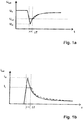
- the Figure 1a shows in dotted lines the evolution over time of the voltage U beats at the terminals of a battery supplying an on-board electrical network of a motor vehicle to which a starter is connected, at the time of launching the heat engine, in lack of stabilization.
- the minimum voltage U m can be much lower than a reference voltage U ref , of the order of 7 to 9 V, set by the vehicle manufacturers as the threshold not to be exceeded.
- the system of stabilization according to the invention makes it possible to maintain the battery voltage U beats at this reference voltage U ref , as is shown by solid lines in FIG. Figure 1a .
- the amplitude of the peak of intensity of the current flow I beats on the same interval ⁇ T is attenuated and has a limited value I L , as shown by solid lines the Figure 1 b.
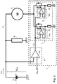
- the Figure 2 schematically shows the implementation of the stabilization system 1 according to the invention in an on-board electrical network 2 of a motor vehicle.
- a battery 3 feeds this network 2 (the ground being connected to the negative pole of the battery 3) to which is connected an electric starter 4, adapted to be mechanically coupled to the engine of the vehicle at the time of launching thereof.
- the stabilization system 1 is a linear regulator designed to stabilize the battery voltage U beats during the start-up phase, by limiting the current draw I beats of the starter 4 to maintain the battery voltage U beats at least at a reference voltage U ref .
- the linear regulator 1 comprises transistors 6 of the MOSFET type in parallel forming a variable resistance in series with the starter 4.
- the transistors 6 are closed (in saturated conditions) and the regulator 1 is equivalent to a simple resistor of small value R DS_ON (of the order of 1 m ⁇ ).
- the stabilization system 1 When the battery voltage U beats falls below the reference voltage U ref (negative voltage variation), the stabilization system 1 is activated and the transistors 6 begin to operate in linear mode as a variable resistor to limit the current I bat .
- the transistors 6 are controlled by two control loops 7, 8, a main current loop 7 and a voltage loop 8.
- the main current loop 7, controls the current flowing in the starter 4 as a function of a reference current I ref .
- the voltage loop 8 is in charge of providing the reference intensity I ref required to maintain the battery voltage U bat , which is also that of the network 2, above the reference voltage U ref .
- the start of the engine requires an intensity I beats of the order of 1000 A and there is currently no power transistor capable of withstanding such intensity under a few volts, it that is to say a power of several kilowatts, in linear mode.
- the gate-source voltage is the same for all. Under these conditions, the threshold voltage V th is not identical for all the transistors 6, there may be in the worst cases of very large differences in the sharing of the current.
- the stabilization system 1 therefore comprises a main current loop 7 formed of several secondary current loops 9 for individually controlling the transistors 6. In this way, the heat dissipation of the transistors 6 is balanced.
- Each secondary current loop uses a grounded shunt 10 for measuring a source current (in the case of an N-channel MOSFET as shown, for a P-channel MOSFET) in each transistor 6 representing the same fraction.
- a source current in the case of an N-channel MOSFET as shown, for a P-channel MOSFET
- I ref the reference intensity
- This operational amplifier 11 generates at its output a gate-source voltage which controls the impedance of the transistor 6 in linear mode in order to slave the source current to the fraction of the reference intensity I ref required.
- Each of the transistors 6 having a feedback, the same reference intensity I ref , or more exactly a voltage representative of this reference intensity I ref , can be applied to all the operational amplifiers 11 which drive them, whatever the number of transistors 6 in parallel.
- the voltage representative of this reference intensity I ref is generated by another operational amplifier 12 as a function of a voltage difference U ref - U bat of the battery 3 with respect to the reference voltage U ref , the voltage U bat of the network 2 being applied to the inverting input and the reference voltage U ref being applied to the non-inverting input.
- the stabilization system 1 has the advantage of avoiding problems of electromagnetic compatibility because it operates in linear mode, and not switching.
- control means of the voltage and current loops 7, 8, 9 are analog based on operational amplifiers 11, 12, it is not necessary to use complex microcontrollers.
- the type of power transistors 6 cited is not limiting; the use of other semiconductor elements capable of performing the same functions as the MOSFETs 6 would not be outside the scope of the invention.
- integrated operational amplifiers 11 is also only one possibility for producing the analog control means of the current loops 7, 9 or of the voltage loop 12; the skilled person can as much as necessary implement the same function at lower cost with discrete or hybrid active elements.
Landscapes
- Engineering & Computer Science (AREA)
- Power Engineering (AREA)
- Chemical & Material Sciences (AREA)
- Combustion & Propulsion (AREA)
- Mechanical Engineering (AREA)
- General Engineering & Computer Science (AREA)
- Control Of Direct Current Motors (AREA)
- Motor And Converter Starters (AREA)
- Charge And Discharge Circuits For Batteries Or The Like (AREA)
- Emergency Protection Circuit Devices (AREA)
Claims (8)
- System zur Stabilisierung (1) einer Versorgungsspannung (Ubat) eines elektrischen Bordnetzes (2) eines Kraftfahrzeugs, vom Typ jener, die eine Spannungsvariation einer Batterie (3), die das Netz (2) versorgt, zum Zeitpunkt eines Startens eines Verbrennungsmotors des Fahrzeugs mit Hilfe eines elektrischen Starters (4), der mit dem Netz (2) verbunden ist, begrenzen, dadurch gekennzeichnet, dass es einen variablen Widerstand (6) umfasst, der in linearem Betrieb in Abhängigkeit von der Spannungsvariation gesteuert wird, wobei der variable Widerstand (6) in Serie mit der Batterie (3) und dem Starter (4) geschaltet ist und von einer Hauptstromschleife (7) in Abhängigkeit von einer Referenzstromstärke (Iref), die von einer Spannungsschleife (8) in Abhängigkeit von der Spannungsvariation in Bezug zu einer Referenzspannung (Uref) erzeugt wird, kontrolliert wird,
wobei der Widerstand (6) von mehreren parallel geschalteten Leistungstransistoren gebildet ist. - System zur Stabilisierung (1) einer Versorgungsspannung (Ubat) eines elektrischen Bordnetzes (2) eines Kraftfahrzeugs nach Anspruch 1, dadurch gekennzeichnet, dass die Transistoren (6) im gesättigten Betrieb funktionieren, wenn die Versorgungsspannung (Ubat) im Absolutwert größer oder gleich der Referenzspannung (Uref) im Absolutwert ist, oder im linearen Betrieb, wenn die Versorgungsspannung (Ubat) im Absolutwert kleiner als die Referenzspannung (Uref) im Absolutwert ist.
- System zur Stabilisierung (1) einer Versorgungsspannung (Ubat) eines elektrischen Bordnetzes (2) eines Kraftfahrzeugs nach Anspruch 2, dadurch gekennzeichnet, dass die Hauptstromschleife (7) von mehreren Nebenstromschleifen (9) gebildet ist, die jeweils jeden der Transistoren (6) in Abhängigkeit von der Referenzstromstärke (Iref) kontrollieren.
- System zur Stabilisierung (1) einer Versorgungsspannung (Ubat) eines elektrischen Bordnetzes (2) eines Kraftfahrzeugs nach Anspruch 3, dadurch gekennzeichnet, dass die Transistoren (6) zwischen dem Starter (4) und einer Masse an ein festes Potential angeschlossen sind.
- System zur Stabilisierung (1) einer Versorgungsspannung (Ubat) eines elektrischen Bordnetzes (2) eines Kraftfahrzeugs nach Anspruch 4, dadurch gekennzeichnet, dass jede der Nebenstromschleifen (9) in Serie mit jedem der Transistoren (6) einen Strommessshunt (10) umfasst, der an die Masse angeschlossen ist.
- System zur Stabilisierung (1) einer Versorgungsspannung (Ubat) eines elektrischen Bordnetzes (2) eines Kraftfahrzeugs nach Anspruch 5, dadurch gekennzeichnet dass die Spannungsschleife (8) und die Nebenstromschleifen (9) analoge Kontrollmittel (11), vorzugsweise Operationsverstärker, umfassen.
- System zur Stabilisierung (1) einer Versorgungsspannung (Ubat) eines elektrischen Bordnetzes (2) eines Kraftfahrzeugs nach einem der Ansprüche 1 bis 6, dadurch gekennzeichnet, dass die Transistoren (6) vom Typ MOSFET sind.
- Starter eines Kraftfahrzeugs, dadurch gekennzeichnet, dass er ein System zur Stabilisierung (1) einer Versorgungsspannung (Ubat) eines elektrischen Bordnetzes (2) nach einem der Ansprüche 1 bis 7 integriert umfasst.
Applications Claiming Priority (2)
| Application Number | Priority Date | Filing Date | Title |
|---|---|---|---|
| FR1356864A FR3008560B1 (fr) | 2013-07-12 | 2013-07-12 | Systeme de stabilisation d'une tension d'alimentation d'un reseau electrique de bord d'un vehicule automobile |
| PCT/FR2014/051663 WO2015004366A1 (fr) | 2013-07-12 | 2014-06-30 | Systeme de stabilisation d'une tension d'alimentation d'un reseau electrique de bord d'un vehicule automobile |
Publications (2)
| Publication Number | Publication Date |
|---|---|
| EP3020109A1 EP3020109A1 (de) | 2016-05-18 |
| EP3020109B1 true EP3020109B1 (de) | 2017-08-30 |
Family
ID=49546530
Family Applications (1)
| Application Number | Title | Priority Date | Filing Date |
|---|---|---|---|
| EP14747067.8A Active EP3020109B1 (de) | 2013-07-12 | 2014-06-30 | System zur stabilisierung der versorgungsspannung eines bordnetzes für ein kraftfahrzeug |
Country Status (4)
| Country | Link |
|---|---|
| EP (1) | EP3020109B1 (de) |
| CN (1) | CN105379041B (de) |
| FR (1) | FR3008560B1 (de) |
| WO (1) | WO2015004366A1 (de) |
Families Citing this family (1)
| Publication number | Priority date | Publication date | Assignee | Title |
|---|---|---|---|---|
| FR3032308B1 (fr) | 2015-01-29 | 2017-02-24 | Valeo Equip Electr Moteur | Systeme de stabilisation d'une tension d'alimentation d'un reseau electrique de bord d'un vehicule automobile |
Family Cites Families (5)
| Publication number | Priority date | Publication date | Assignee | Title |
|---|---|---|---|---|
| FR2843841B1 (fr) | 2002-08-26 | 2009-12-11 | Valeo Equip Electr Moteur | Dispositif et procede de commande d'une machine electrique tournante pour vehicule |
| DE102009047497A1 (de) * | 2009-12-04 | 2011-06-09 | Robert Bosch Gmbh | Bauelement zur Begrenzung von Strömen in elektrischen Schaltungen |
| DE102010039875A1 (de) * | 2010-08-27 | 2012-03-01 | Robert Bosch Gmbh | Verfahren und Vorrichtung zum Betreiben eines Starters eines Fahrzeugs |
| DE102010046232A1 (de) * | 2010-09-22 | 2011-05-05 | Daimler Ag | Einrichtung zur Stabilisierung einer Versorgungsspannung in einem Kraftfahrzeug |
| FR2978499B1 (fr) | 2011-07-28 | 2018-03-02 | Valeo Equipements Electriques Moteur | Circuit de demarreur de vehicule automobile comportant un dispositif de rehaussement de tension de batterie et demarreur equipe |
-
2013
- 2013-07-12 FR FR1356864A patent/FR3008560B1/fr active Active
-
2014
- 2014-06-30 EP EP14747067.8A patent/EP3020109B1/de active Active
- 2014-06-30 WO PCT/FR2014/051663 patent/WO2015004366A1/fr not_active Ceased
- 2014-06-30 CN CN201480039856.8A patent/CN105379041B/zh active Active
Non-Patent Citations (1)
| Title |
|---|
| None * |
Also Published As
| Publication number | Publication date |
|---|---|
| WO2015004366A1 (fr) | 2015-01-15 |
| FR3008560B1 (fr) | 2019-12-20 |
| EP3020109A1 (de) | 2016-05-18 |
| CN105379041B (zh) | 2019-03-01 |
| CN105379041A (zh) | 2016-03-02 |
| FR3008560A1 (fr) | 2015-01-16 |
Similar Documents
| Publication | Publication Date | Title |
|---|---|---|
| EP3105845B1 (de) | Gleichspannungsversorgungssystem zur vorladung eines glättungskondensators vor der speisung einer last | |
| EP2794356B1 (de) | Vorrichtung zur bewahrung der spannung während der anschaltphase für ein kraftfahrzeug | |
| EP1790071B1 (de) | Steuer- und stromversorgungsmodul für eine rotierende elektrische maschine | |
| EP2794340B1 (de) | Vorrichtung zum verbinden/lösen einer ladung für eine energiespeichereinheit in einem kraftfahrzeug | |
| WO2014106576A1 (fr) | Systeme comprenant une batterie formee de modules de batterie, et procede de connexion ou de deconnexion d'un module de batterie correspondant | |
| WO2016170262A1 (fr) | Regulateur de tension d'un alternateur de vehicule automobile, porte-balais regulateur et alternateurs correspondants | |
| FR2960265A1 (fr) | Dispositif de demarrage de moteur thermique | |
| EP3020109B1 (de) | System zur stabilisierung der versorgungsspannung eines bordnetzes für ein kraftfahrzeug | |
| EP2053720A1 (de) | Schnittstellenvorrichtung zur Spannungskompensation durch kapazitive Energiespeicherung und mit einer solchen Vorrichtung ausgestattetes Stromnetz | |
| EP2823179B1 (de) | Verfahren zur begrenzung eines zustroms in einer stromschaltung eines kraftfahrzeug-anlassers sowie entsprechende elektrische schaltung, strombegrenzer und anlasser | |
| EP3020110B1 (de) | Verfahren und system zur stabilisierung der versorgungsspannung eines bordnetzes eines kraftfahrzeugs | |
| EP3127212B1 (de) | System zur stabilisierung einer versorgungsspannung eines stromnetzes an bord eines kraftfahrzeugs | |
| EP1946972A1 (de) | Vorrichtung zur vorübergehenden Erhöhung der elektrischen Spannung für Automobilelement | |
| EP2991225A1 (de) | Statisches steuerrelais eines elektrischen anlassers eines kraftfahrzeugs, und entsprechender elektrischer anlasser eines kraftfahrzeugs | |
| WO2011092384A2 (fr) | Dispositif d'interface entre deux parties d'un reseau electrique | |
| FR3032308A1 (fr) | Systeme de stabilisation d'une tension d'alimentation d'un reseau electrique de bord d'un vehicule automobile | |
| WO2007080349A1 (fr) | Dispositif d'alimentation de l'inducteur d'une machine electrique tournante | |
| FR3063843A1 (fr) | Circuit electrique de decharge d'une capacite, systeme electrique et vehicule automobile comportant un tel circuit electrique de decharge | |
| FR3013534A1 (fr) | Alimentation d'un moteur electrique | |
| FR2985617A1 (fr) | Dispositif d'alimentation electrique d'un vehicule automobile hybride et vehicule automobile hybride correspondant | |
| FR2942359A1 (fr) | Dispositif et procede d'aide au demarrage d'un moteur thermique | |
| WO2013041793A1 (fr) | Procede et systeme de controle de la charge progressive d'un alternateur de vehicule automobile, et alternateur de vehicule automobile comprenant un tel systeme | |
| FR2882474A1 (fr) | Circuit d'alimentation d'un inducteur d'alternateur, notamment pour vehicule automobile |
Legal Events
| Date | Code | Title | Description |
|---|---|---|---|
| PUAI | Public reference made under article 153(3) epc to a published international application that has entered the european phase |
Free format text: ORIGINAL CODE: 0009012 |
|
| 17P | Request for examination filed |
Effective date: 20160107 |
|
| AK | Designated contracting states |
Kind code of ref document: A1 Designated state(s): AL AT BE BG CH CY CZ DE DK EE ES FI FR GB GR HR HU IE IS IT LI LT LU LV MC MK MT NL NO PL PT RO RS SE SI SK SM TR |
|
| AX | Request for extension of the european patent |
Extension state: BA ME |
|
| DAX | Request for extension of the european patent (deleted) | ||
| GRAP | Despatch of communication of intention to grant a patent |
Free format text: ORIGINAL CODE: EPIDOSNIGR1 |
|
| INTG | Intention to grant announced |
Effective date: 20170324 |
|
| GRAS | Grant fee paid |
Free format text: ORIGINAL CODE: EPIDOSNIGR3 |
|
| GRAA | (expected) grant |
Free format text: ORIGINAL CODE: 0009210 |
|
| AK | Designated contracting states |
Kind code of ref document: B1 Designated state(s): AL AT BE BG CH CY CZ DE DK EE ES FI FR GB GR HR HU IE IS IT LI LT LU LV MC MK MT NL NO PL PT RO RS SE SI SK SM TR |
|
| REG | Reference to a national code |
Ref country code: GB Ref legal event code: FG4D Free format text: NOT ENGLISH |
|
| REG | Reference to a national code |
Ref country code: CH Ref legal event code: EP |
|
| REG | Reference to a national code |
Ref country code: AT Ref legal event code: REF Ref document number: 924491 Country of ref document: AT Kind code of ref document: T Effective date: 20170915 |
|
| REG | Reference to a national code |
Ref country code: IE Ref legal event code: FG4D Free format text: LANGUAGE OF EP DOCUMENT: FRENCH |
|
| REG | Reference to a national code |
Ref country code: DE Ref legal event code: R096 Ref document number: 602014013872 Country of ref document: DE |
|
| REG | Reference to a national code |
Ref country code: NL Ref legal event code: MP Effective date: 20170830 |
|
| REG | Reference to a national code |
Ref country code: LT Ref legal event code: MG4D |
|
| REG | Reference to a national code |
Ref country code: AT Ref legal event code: MK05 Ref document number: 924491 Country of ref document: AT Kind code of ref document: T Effective date: 20170830 |
|
| PG25 | Lapsed in a contracting state [announced via postgrant information from national office to epo] |
Ref country code: FI Free format text: LAPSE BECAUSE OF FAILURE TO SUBMIT A TRANSLATION OF THE DESCRIPTION OR TO PAY THE FEE WITHIN THE PRESCRIBED TIME-LIMIT Effective date: 20170830 Ref country code: HR Free format text: LAPSE BECAUSE OF FAILURE TO SUBMIT A TRANSLATION OF THE DESCRIPTION OR TO PAY THE FEE WITHIN THE PRESCRIBED TIME-LIMIT Effective date: 20170830 Ref country code: NO Free format text: LAPSE BECAUSE OF FAILURE TO SUBMIT A TRANSLATION OF THE DESCRIPTION OR TO PAY THE FEE WITHIN THE PRESCRIBED TIME-LIMIT Effective date: 20171130 Ref country code: AT Free format text: LAPSE BECAUSE OF FAILURE TO SUBMIT A TRANSLATION OF THE DESCRIPTION OR TO PAY THE FEE WITHIN THE PRESCRIBED TIME-LIMIT Effective date: 20170830 Ref country code: LT Free format text: LAPSE BECAUSE OF FAILURE TO SUBMIT A TRANSLATION OF THE DESCRIPTION OR TO PAY THE FEE WITHIN THE PRESCRIBED TIME-LIMIT Effective date: 20170830 Ref country code: SE Free format text: LAPSE BECAUSE OF FAILURE TO SUBMIT A TRANSLATION OF THE DESCRIPTION OR TO PAY THE FEE WITHIN THE PRESCRIBED TIME-LIMIT Effective date: 20170830 |
|
| PG25 | Lapsed in a contracting state [announced via postgrant information from national office to epo] |
Ref country code: ES Free format text: LAPSE BECAUSE OF FAILURE TO SUBMIT A TRANSLATION OF THE DESCRIPTION OR TO PAY THE FEE WITHIN THE PRESCRIBED TIME-LIMIT Effective date: 20170830 Ref country code: LV Free format text: LAPSE BECAUSE OF FAILURE TO SUBMIT A TRANSLATION OF THE DESCRIPTION OR TO PAY THE FEE WITHIN THE PRESCRIBED TIME-LIMIT Effective date: 20170830 Ref country code: IS Free format text: LAPSE BECAUSE OF FAILURE TO SUBMIT A TRANSLATION OF THE DESCRIPTION OR TO PAY THE FEE WITHIN THE PRESCRIBED TIME-LIMIT Effective date: 20171230 Ref country code: GR Free format text: LAPSE BECAUSE OF FAILURE TO SUBMIT A TRANSLATION OF THE DESCRIPTION OR TO PAY THE FEE WITHIN THE PRESCRIBED TIME-LIMIT Effective date: 20171201 Ref country code: RS Free format text: LAPSE BECAUSE OF FAILURE TO SUBMIT A TRANSLATION OF THE DESCRIPTION OR TO PAY THE FEE WITHIN THE PRESCRIBED TIME-LIMIT Effective date: 20170830 Ref country code: BG Free format text: LAPSE BECAUSE OF FAILURE TO SUBMIT A TRANSLATION OF THE DESCRIPTION OR TO PAY THE FEE WITHIN THE PRESCRIBED TIME-LIMIT Effective date: 20171130 |
|
| PG25 | Lapsed in a contracting state [announced via postgrant information from national office to epo] |
Ref country code: NL Free format text: LAPSE BECAUSE OF FAILURE TO SUBMIT A TRANSLATION OF THE DESCRIPTION OR TO PAY THE FEE WITHIN THE PRESCRIBED TIME-LIMIT Effective date: 20170830 |
|
| PG25 | Lapsed in a contracting state [announced via postgrant information from national office to epo] |
Ref country code: RO Free format text: LAPSE BECAUSE OF FAILURE TO SUBMIT A TRANSLATION OF THE DESCRIPTION OR TO PAY THE FEE WITHIN THE PRESCRIBED TIME-LIMIT Effective date: 20170830 Ref country code: DK Free format text: LAPSE BECAUSE OF FAILURE TO SUBMIT A TRANSLATION OF THE DESCRIPTION OR TO PAY THE FEE WITHIN THE PRESCRIBED TIME-LIMIT Effective date: 20170830 Ref country code: CZ Free format text: LAPSE BECAUSE OF FAILURE TO SUBMIT A TRANSLATION OF THE DESCRIPTION OR TO PAY THE FEE WITHIN THE PRESCRIBED TIME-LIMIT Effective date: 20170830 Ref country code: PL Free format text: LAPSE BECAUSE OF FAILURE TO SUBMIT A TRANSLATION OF THE DESCRIPTION OR TO PAY THE FEE WITHIN THE PRESCRIBED TIME-LIMIT Effective date: 20170830 |
|
| PG25 | Lapsed in a contracting state [announced via postgrant information from national office to epo] |
Ref country code: SM Free format text: LAPSE BECAUSE OF FAILURE TO SUBMIT A TRANSLATION OF THE DESCRIPTION OR TO PAY THE FEE WITHIN THE PRESCRIBED TIME-LIMIT Effective date: 20170830 Ref country code: IT Free format text: LAPSE BECAUSE OF FAILURE TO SUBMIT A TRANSLATION OF THE DESCRIPTION OR TO PAY THE FEE WITHIN THE PRESCRIBED TIME-LIMIT Effective date: 20170830 Ref country code: SK Free format text: LAPSE BECAUSE OF FAILURE TO SUBMIT A TRANSLATION OF THE DESCRIPTION OR TO PAY THE FEE WITHIN THE PRESCRIBED TIME-LIMIT Effective date: 20170830 Ref country code: EE Free format text: LAPSE BECAUSE OF FAILURE TO SUBMIT A TRANSLATION OF THE DESCRIPTION OR TO PAY THE FEE WITHIN THE PRESCRIBED TIME-LIMIT Effective date: 20170830 |
|
| REG | Reference to a national code |
Ref country code: DE Ref legal event code: R097 Ref document number: 602014013872 Country of ref document: DE |
|
| REG | Reference to a national code |
Ref country code: FR Ref legal event code: PLFP Year of fee payment: 5 |
|
| PLBE | No opposition filed within time limit |
Free format text: ORIGINAL CODE: 0009261 |
|
| STAA | Information on the status of an ep patent application or granted ep patent |
Free format text: STATUS: NO OPPOSITION FILED WITHIN TIME LIMIT |
|
| 26N | No opposition filed |
Effective date: 20180531 |
|
| PG25 | Lapsed in a contracting state [announced via postgrant information from national office to epo] |
Ref country code: SI Free format text: LAPSE BECAUSE OF FAILURE TO SUBMIT A TRANSLATION OF THE DESCRIPTION OR TO PAY THE FEE WITHIN THE PRESCRIBED TIME-LIMIT Effective date: 20170830 |
|
| PG25 | Lapsed in a contracting state [announced via postgrant information from national office to epo] |
Ref country code: MT Free format text: LAPSE BECAUSE OF FAILURE TO SUBMIT A TRANSLATION OF THE DESCRIPTION OR TO PAY THE FEE WITHIN THE PRESCRIBED TIME-LIMIT Effective date: 20170830 |
|
| REG | Reference to a national code |
Ref country code: CH Ref legal event code: PL |
|
| GBPC | Gb: european patent ceased through non-payment of renewal fee |
Effective date: 20180630 |
|
| REG | Reference to a national code |
Ref country code: BE Ref legal event code: MM Effective date: 20180630 |
|
| PG25 | Lapsed in a contracting state [announced via postgrant information from national office to epo] |
Ref country code: MC Free format text: LAPSE BECAUSE OF FAILURE TO SUBMIT A TRANSLATION OF THE DESCRIPTION OR TO PAY THE FEE WITHIN THE PRESCRIBED TIME-LIMIT Effective date: 20170830 Ref country code: LU Free format text: LAPSE BECAUSE OF NON-PAYMENT OF DUE FEES Effective date: 20180630 |
|
| REG | Reference to a national code |
Ref country code: IE Ref legal event code: MM4A |
|
| PG25 | Lapsed in a contracting state [announced via postgrant information from national office to epo] |
Ref country code: LI Free format text: LAPSE BECAUSE OF NON-PAYMENT OF DUE FEES Effective date: 20180630 Ref country code: CH Free format text: LAPSE BECAUSE OF NON-PAYMENT OF DUE FEES Effective date: 20180630 Ref country code: IE Free format text: LAPSE BECAUSE OF NON-PAYMENT OF DUE FEES Effective date: 20180630 Ref country code: GB Free format text: LAPSE BECAUSE OF NON-PAYMENT OF DUE FEES Effective date: 20180630 |
|
| PG25 | Lapsed in a contracting state [announced via postgrant information from national office to epo] |
Ref country code: BE Free format text: LAPSE BECAUSE OF NON-PAYMENT OF DUE FEES Effective date: 20180630 |
|
| PG25 | Lapsed in a contracting state [announced via postgrant information from national office to epo] |
Ref country code: TR Free format text: LAPSE BECAUSE OF FAILURE TO SUBMIT A TRANSLATION OF THE DESCRIPTION OR TO PAY THE FEE WITHIN THE PRESCRIBED TIME-LIMIT Effective date: 20170830 |
|
| PG25 | Lapsed in a contracting state [announced via postgrant information from national office to epo] |
Ref country code: PT Free format text: LAPSE BECAUSE OF FAILURE TO SUBMIT A TRANSLATION OF THE DESCRIPTION OR TO PAY THE FEE WITHIN THE PRESCRIBED TIME-LIMIT Effective date: 20170830 |
|
| PG25 | Lapsed in a contracting state [announced via postgrant information from national office to epo] |
Ref country code: HU Free format text: LAPSE BECAUSE OF FAILURE TO SUBMIT A TRANSLATION OF THE DESCRIPTION OR TO PAY THE FEE WITHIN THE PRESCRIBED TIME-LIMIT; INVALID AB INITIO Effective date: 20140630 Ref country code: MK Free format text: LAPSE BECAUSE OF NON-PAYMENT OF DUE FEES Effective date: 20170830 Ref country code: CY Free format text: LAPSE BECAUSE OF FAILURE TO SUBMIT A TRANSLATION OF THE DESCRIPTION OR TO PAY THE FEE WITHIN THE PRESCRIBED TIME-LIMIT Effective date: 20170830 |
|
| PG25 | Lapsed in a contracting state [announced via postgrant information from national office to epo] |
Ref country code: AL Free format text: LAPSE BECAUSE OF FAILURE TO SUBMIT A TRANSLATION OF THE DESCRIPTION OR TO PAY THE FEE WITHIN THE PRESCRIBED TIME-LIMIT Effective date: 20170830 |
|
| P01 | Opt-out of the competence of the unified patent court (upc) registered |
Effective date: 20230528 |
|
| PGFP | Annual fee paid to national office [announced via postgrant information from national office to epo] |
Ref country code: DE Payment date: 20250617 Year of fee payment: 12 |
|
| PGFP | Annual fee paid to national office [announced via postgrant information from national office to epo] |
Ref country code: FR Payment date: 20250630 Year of fee payment: 12 |