EP3020113B1 - Vorrichtung zur steuerung einer stromlast in einem elektrischen netz und zugehöriges verfahren und system - Google Patents
Vorrichtung zur steuerung einer stromlast in einem elektrischen netz und zugehöriges verfahren und system Download PDFInfo
- Publication number
- EP3020113B1 EP3020113B1 EP14744377.4A EP14744377A EP3020113B1 EP 3020113 B1 EP3020113 B1 EP 3020113B1 EP 14744377 A EP14744377 A EP 14744377A EP 3020113 B1 EP3020113 B1 EP 3020113B1
- Authority
- EP
- European Patent Office
- Prior art keywords
- power
- network
- power load
- remote control
- control command
- Prior art date
- Legal status (The legal status is an assumption and is not a legal conclusion. Google has not performed a legal analysis and makes no representation as to the accuracy of the status listed.)
- Active
Links
Images


Classifications
-
- H—ELECTRICITY
- H02—GENERATION; CONVERSION OR DISTRIBUTION OF ELECTRIC POWER
- H02J—ELECTRIC POWER NETWORKS; CIRCUIT ARRANGEMENTS OR SYSTEMS FOR SUPPLYING OR DISTRIBUTING ELECTRIC POWER; SYSTEMS FOR STORING ELECTRIC ENERGY
- H02J3/00—Circuit arrangements for AC mains or AC distribution networks
-
- G—PHYSICS
- G05—CONTROLLING; REGULATING
- G05B—CONTROL OR REGULATING SYSTEMS IN GENERAL; FUNCTIONAL ELEMENTS OF SUCH SYSTEMS; MONITORING OR TESTING ARRANGEMENTS FOR SUCH SYSTEMS OR ELEMENTS
- G05B19/00—Program-control systems
- G05B19/02—Program-control systems electric
- G05B19/04—Program control other than numerical control, i.e. in sequence controllers or logic controllers
- G05B19/10—Program control other than numerical control, i.e. in sequence controllers or logic controllers using selector switches
- G05B19/102—Program control other than numerical control, i.e. in sequence controllers or logic controllers using selector switches for input of program steps, i.e. setting up sequence
-
- H—ELECTRICITY
- H02—GENERATION; CONVERSION OR DISTRIBUTION OF ELECTRIC POWER
- H02J—ELECTRIC POWER NETWORKS; CIRCUIT ARRANGEMENTS OR SYSTEMS FOR SUPPLYING OR DISTRIBUTING ELECTRIC POWER; SYSTEMS FOR STORING ELECTRIC ENERGY
- H02J13/00—Circuit arrangements for providing remote monitoring or remote control of equipment in a power distribution network
- H02J13/13—Circuit arrangements for providing remote monitoring or remote control of equipment in a power distribution network characterised by the transmission of data to equipment in the power network
- H02J13/1321—Circuit arrangements for providing remote monitoring or remote control of equipment in a power distribution network characterised by the transmission of data to equipment in the power network using a wired telecommunication network or a data transmission bus
- H02J13/1323—Circuit arrangements for providing remote monitoring or remote control of equipment in a power distribution network characterised by the transmission of data to equipment in the power network using a wired telecommunication network or a data transmission bus using optical fibres
-
- H—ELECTRICITY
- H02—GENERATION; CONVERSION OR DISTRIBUTION OF ELECTRIC POWER
- H02J—ELECTRIC POWER NETWORKS; CIRCUIT ARRANGEMENTS OR SYSTEMS FOR SUPPLYING OR DISTRIBUTING ELECTRIC POWER; SYSTEMS FOR STORING ELECTRIC ENERGY
- H02J13/00—Circuit arrangements for providing remote monitoring or remote control of equipment in a power distribution network
- H02J13/18—Circuit arrangements for providing remote monitoring or remote control of equipment in a power distribution network characterised by the remotely-controlled equipment, e.g. converters or transformers
- H02J13/333—Circuit arrangements for providing remote monitoring or remote control of equipment in a power distribution network characterised by the remotely-controlled equipment, e.g. converters or transformers the equipment forming part of substations
-
- H—ELECTRICITY
- H02—GENERATION; CONVERSION OR DISTRIBUTION OF ELECTRIC POWER
- H02J—ELECTRIC POWER NETWORKS; CIRCUIT ARRANGEMENTS OR SYSTEMS FOR SUPPLYING OR DISTRIBUTING ELECTRIC POWER; SYSTEMS FOR STORING ELECTRIC ENERGY
- H02J3/00—Circuit arrangements for AC mains or AC distribution networks
- H02J3/12—Arrangements for adjusting voltage in AC networks by changing a characteristic of the network load
- H02J3/14—Arrangements for adjusting voltage in AC networks by changing a characteristic of the network load by switching loads on to, or off from, the networks, e.g. progressively balanced loading
-
- G—PHYSICS
- G05—CONTROLLING; REGULATING
- G05B—CONTROL OR REGULATING SYSTEMS IN GENERAL; FUNCTIONAL ELEMENTS OF SUCH SYSTEMS; MONITORING OR TESTING ARRANGEMENTS FOR SUCH SYSTEMS OR ELEMENTS
- G05B2219/00—Program-control systems
- G05B2219/20—Pc systems
- G05B2219/26—Pc applications
- G05B2219/2639—Energy management, use maximum of cheap power, keep peak load low
-
- H—ELECTRICITY
- H02—GENERATION; CONVERSION OR DISTRIBUTION OF ELECTRIC POWER
- H02J—ELECTRIC POWER NETWORKS; CIRCUIT ARRANGEMENTS OR SYSTEMS FOR SUPPLYING OR DISTRIBUTING ELECTRIC POWER; SYSTEMS FOR STORING ELECTRIC ENERGY
- H02J13/00—Circuit arrangements for providing remote monitoring or remote control of equipment in a power distribution network
-
- H—ELECTRICITY
- H02—GENERATION; CONVERSION OR DISTRIBUTION OF ELECTRIC POWER
- H02J—ELECTRIC POWER NETWORKS; CIRCUIT ARRANGEMENTS OR SYSTEMS FOR SUPPLYING OR DISTRIBUTING ELECTRIC POWER; SYSTEMS FOR STORING ELECTRIC ENERGY
- H02J2105/00—Networks for supplying or distributing electric power characterised by their spatial reach or by the load
- H02J2105/50—Networks for supplying or distributing electric power characterised by their spatial reach or by the load for selectively controlling the operation of the loads
- H02J2105/54—Networks for supplying or distributing electric power characterised by their spatial reach or by the load for selectively controlling the operation of the loads according to a non-electrical condition, e.g. temperature
- H02J2105/55—Networks for supplying or distributing electric power characterised by their spatial reach or by the load for selectively controlling the operation of the loads according to a non-electrical condition, e.g. temperature according to an economic condition, e.g. tariff-based load management
-
- Y—GENERAL TAGGING OF NEW TECHNOLOGICAL DEVELOPMENTS; GENERAL TAGGING OF CROSS-SECTIONAL TECHNOLOGIES SPANNING OVER SEVERAL SECTIONS OF THE IPC; TECHNICAL SUBJECTS COVERED BY FORMER USPC CROSS-REFERENCE ART COLLECTIONS [XRACs] AND DIGESTS
- Y02—TECHNOLOGIES OR APPLICATIONS FOR MITIGATION OR ADAPTATION AGAINST CLIMATE CHANGE
- Y02B—CLIMATE CHANGE MITIGATION TECHNOLOGIES RELATED TO BUILDINGS, e.g. HOUSING, HOUSE APPLIANCES OR RELATED END-USER APPLICATIONS
- Y02B70/00—Technologies for an efficient end-user side electric power management and consumption
- Y02B70/30—Systems integrating technologies related to power network operation and communication or information technologies for improving the carbon footprint of the management of residential or tertiary loads, i.e. smart grids as climate change mitigation technology in the buildings sector, including also the last stages of power distribution and the control, monitoring or operating management systems at local level
- Y02B70/3225—Demand response systems, e.g. load shedding, peak shaving
-
- Y—GENERAL TAGGING OF NEW TECHNOLOGICAL DEVELOPMENTS; GENERAL TAGGING OF CROSS-SECTIONAL TECHNOLOGIES SPANNING OVER SEVERAL SECTIONS OF THE IPC; TECHNICAL SUBJECTS COVERED BY FORMER USPC CROSS-REFERENCE ART COLLECTIONS [XRACs] AND DIGESTS
- Y02—TECHNOLOGIES OR APPLICATIONS FOR MITIGATION OR ADAPTATION AGAINST CLIMATE CHANGE
- Y02B—CLIMATE CHANGE MITIGATION TECHNOLOGIES RELATED TO BUILDINGS, e.g. HOUSING, HOUSE APPLIANCES OR RELATED END-USER APPLICATIONS
- Y02B90/00—Enabling technologies or technologies with a potential or indirect contribution to GHG emissions mitigation
- Y02B90/20—Smart grids as enabling technology in buildings sector
-
- Y—GENERAL TAGGING OF NEW TECHNOLOGICAL DEVELOPMENTS; GENERAL TAGGING OF CROSS-SECTIONAL TECHNOLOGIES SPANNING OVER SEVERAL SECTIONS OF THE IPC; TECHNICAL SUBJECTS COVERED BY FORMER USPC CROSS-REFERENCE ART COLLECTIONS [XRACs] AND DIGESTS
- Y04—INFORMATION OR COMMUNICATION TECHNOLOGIES HAVING AN IMPACT ON OTHER TECHNOLOGY AREAS
- Y04S—SYSTEMS INTEGRATING TECHNOLOGIES RELATED TO POWER NETWORK OPERATION, COMMUNICATION OR INFORMATION TECHNOLOGIES FOR IMPROVING THE ELECTRICAL POWER GENERATION, TRANSMISSION, DISTRIBUTION, MANAGEMENT OR USAGE, i.e. SMART GRIDS
- Y04S20/00—Management or operation of end-user stationary applications or the last stages of power distribution; Controlling, monitoring or operating thereof
-
- Y—GENERAL TAGGING OF NEW TECHNOLOGICAL DEVELOPMENTS; GENERAL TAGGING OF CROSS-SECTIONAL TECHNOLOGIES SPANNING OVER SEVERAL SECTIONS OF THE IPC; TECHNICAL SUBJECTS COVERED BY FORMER USPC CROSS-REFERENCE ART COLLECTIONS [XRACs] AND DIGESTS
- Y04—INFORMATION OR COMMUNICATION TECHNOLOGIES HAVING AN IMPACT ON OTHER TECHNOLOGY AREAS
- Y04S—SYSTEMS INTEGRATING TECHNOLOGIES RELATED TO POWER NETWORK OPERATION, COMMUNICATION OR INFORMATION TECHNOLOGIES FOR IMPROVING THE ELECTRICAL POWER GENERATION, TRANSMISSION, DISTRIBUTION, MANAGEMENT OR USAGE, i.e. SMART GRIDS
- Y04S20/00—Management or operation of end-user stationary applications or the last stages of power distribution; Controlling, monitoring or operating thereof
- Y04S20/20—End-user application control systems
- Y04S20/222—Demand response systems, e.g. load shedding, peak shaving
-
- Y—GENERAL TAGGING OF NEW TECHNOLOGICAL DEVELOPMENTS; GENERAL TAGGING OF CROSS-SECTIONAL TECHNOLOGIES SPANNING OVER SEVERAL SECTIONS OF THE IPC; TECHNICAL SUBJECTS COVERED BY FORMER USPC CROSS-REFERENCE ART COLLECTIONS [XRACs] AND DIGESTS
- Y04—INFORMATION OR COMMUNICATION TECHNOLOGIES HAVING AN IMPACT ON OTHER TECHNOLOGY AREAS
- Y04S—SYSTEMS INTEGRATING TECHNOLOGIES RELATED TO POWER NETWORK OPERATION, COMMUNICATION OR INFORMATION TECHNOLOGIES FOR IMPROVING THE ELECTRICAL POWER GENERATION, TRANSMISSION, DISTRIBUTION, MANAGEMENT OR USAGE, i.e. SMART GRIDS
- Y04S50/00—Market activities related to the operation of systems integrating technologies related to power network operation or related to communication or information technologies
- Y04S50/10—Energy trading, including energy flowing from end-user application to grid
Definitions
- the invention lies in the field of management of electrical energy networks.
- the state of the art in the management of power loads in the terminal electrical installations of an electricity network is to enslave the start-up and shutdown of these loads at tariff conditions.
- the best known case being the servocontrol of the operation of a water-electric heater at the off-peak / peak hour rate.
- the technical solutions implemented to control the power loads in the terminal installations are interleaved with the tariff management solutions as shown by the patent.
- FR2947396 The energy meters generally include a remote control receiver which makes it possible to change the count indexes according to the tariff periods, as for example in the patent.
- FR2636142 These state-of-the-art counters include a control relay for controlling an external power relay to automatically control the operating status of the water heater at the current tariff status.
- the aim of the present invention is to remedy at least partially the problems mentioned above by proposing a device for controlling the operation of a power load belonging to a terminal electrical installation according to events relating to the operation or management of an electrical distribution network.
- This device can advantageously be used by the manager of a power distribution network to keep it in an optimal operating state through the use of resources in the terminal facilities.
- the terminal installations in which it is intended to implement the invention belong to the so-called low-voltage part of an electrical network. It is most often to drive single-phase power loads powered by an AC voltage which is for example 230 V at a frequency of 50 Hz in Europe and 110 V at a frequency of 60 Hz in North America.
- the invention can also be implemented in three-phase terminal installations, and / or to control three-phase loads where appropriate.
- the power load must be understood as a single power load or as a plurality of elementary loads controlled collectively or differentially.
- the control of the power load must be understood as being in all or nothing, ie as being a start or stop of the power load or as a setting in intermediate functional states.
- the so-called intermediate functional states call a power on the network which is non-zero and less than the maximum power of the load.
- the fact of extracting the at least one instruction from the single voltage is particularly advantageous in that the device can be installed at any point of the terminal electrical installation, even outside the electrical panel which concentrates in general all the equipment of installation. It is thus provided in certain implementation variants to integrate the device according to the invention directly into electrical devices comprising one or more power loads such as electric resistance or thermodynamic water heaters, electric heating devices with resistance, thermodynamic cooling or heating devices etc.
- the fact of including the device in the apparatus containing at least one power load also offers the advantage of enabling smarter management of the at least one load, taking into account, for example, internal operating cycles or constraints. use. It also allows multiple load levels to be handled in the load, sequencing the start of the at least one load over time to maintain a minimum level of service, to maintain the power of features of the device that does not do not concern the power charge etc.
- the device according to the invention comprises means for switching the electrical power supply of the power load to be controlled. This is the easiest way to control external power loads without associated intelligence such as domestic hot water appliances or heaters based on the use of power resistors.
- an appropriate interface between the electronics of the device according to the invention and the electronic management of the power load in the device. Such an interface may for example be based on the use of one or more optocouplers.
- the device comprises means for switching the electrical power supply of the power load
- the load is supplied by default.
- the device is arranged so that the power load is fed by the normally closed contacts of a relay. so that the power device is still powered and the service provided in case of failure of the device according to the invention. This is all the more appropriate that the device according to the invention is more useful to the power grid manager than to the user of the device.
- the device according to the invention comprises means for remotely controlling the operation of an integrated power load in a device that can be controlled remotely. It may be a wireless remote control transmitter whose physical layer, for example infrared or radio frequency, and coding commands are arranged to control the operation of an apparatus containing one or more power loads.
- a wireless remote control transmitter whose physical layer, for example infrared or radio frequency, and coding commands are arranged to control the operation of an apparatus containing one or more power loads.
- This variant allows the device according to the invention to be implemented in the form of an optional accessory of the device to be controlled and / or to simplify the functional coupling of the device with a sophisticated external device.
- This variant of the invention is particularly suitable for driving reversible or non-reversible air conditioners that integrate a remote control receiver.
- It may also be a wired remote control such as an interface capable of controlling one or more power devices having an optional control input called "pilot wire” as electric convectors. It can also be a wired or wireless interface between the device and a home automation system or a building management system capable of acting on the functional state of one or more power loads in the electrical installation. terminal concerned.
- the functional block for extracting at least one setpoint from the voltage of the terminal electrical installation is a receiver of so-called centralized remote control signals with musical frequency, the at least one setpoint being a remote control command.
- This variant of the invention is intended to be installed in electrical networks where the tariff management infrastructures use remote controls known as musical frequency.
- This remote control mode relies for example on pulses modulating in all or nothing a sinusoidal signal at 175 Hz or at 188 Hz superimposed on the mains voltage, the frequencies used and the coding of the pulses varying according to the countries.
- the functional block for extracting at least one setpoint from the voltage of the terminal electrical installation is a receiver of remote control signals transmitted by carrier currents in a low voltage line. at least one setpoint being a remote control command.
- This variant of the invention is intended to be installed in electrical networks where the tariff management infrastructures use power line transmissions at least in their low voltage part serving the terminal electrical installations. This may be for example transmissions remote commands and remote reading according to IEC 61334 and IEC 62056 standards as in France or other standards that vary from country to country. It should be noted that if for the purposes of electricity tariff management the meters need to implement a bidirectional powerline transmitter, substantial savings can be made in the device according to the invention by not putting only the receiving part of a carrier transmitter. The own power consumption of the device is also advantageously reduced by the absence of emitting part.
- the device according to the invention comprises means for receiving radiofrequency transmitted remote control signals, the at least one setpoint being a remote control command.
- This variant of the invention is intended to be installed in electrical networks where the tariff management infrastructures use means of radio transmissions. It can be means of transmission short-range radiofrequency (ZigBee, Bluetooth, Wi-Fi or other equivalent standards and successors) or the use of wireless telecom networks (eg GSM from 1G to 4G or equivalent and successors).
- the invention furthermore provides that the functional block for extracting at least one setpoint from the voltage of the terminal electrical installation of the device uses the value of the voltage and / or its evolution over time in order to deduce the value of the voltage. at least one instruction.
- This characteristic can give rise to an autonomous implementation in a dedicated variant of the device according to the invention.
- the autonomy of the device in this variant is based on the fact that it requires no remote control from the network manager.
- the detection of the problem and the corresponding action on the power load are indeed managed locally in the device.
- the fully decentralized and diffuse management of the network that results from the implementation of this variant of the invention is economical in terms of infrastructure and particularly effective in terms of reaction time.
- this variant of the invention may advantageously be combined with the previous variants.
- the implementation of this functionality requires only a little software and few or no additional electronic components.
- This variant of the invention may for example be used to allow the network to self-stabilize more quickly than with any other solution based on centralized management of the network and on remote controls. This by using the power loads of terminal installations to dampen the oscillations that may arise within the network in certain circumstances.
- the device extracted from the voltage has at its terminals a setpoint leading to automatically feed during a short period of for example a few tens of seconds to several minutes the power load it controls.
- the extraction of the setpoint can for example take into account the amplitude of the voltage supplying the terminal installation and the speed of variation of this amplitude to correspond to the detection of an oscillatory phenomenon on the electrical network.
- the invention provides for automatic disconnection of the power loads in the event of abnormal undervoltage of a duration greater than a predetermined value which is the probable sign of a overload of the distribution network which could lead to a blackout. Solutions for spreading from the tip to the reconnection will advantageously be implemented, such as those to be described later, to avoid recreating a phenomenon of overload later and / or to prevent the appearance of any oscillatory phenomenon.
- This functional variant of the invention if it was implemented in a generalized manner in a given territory, is particularly interesting in that it allows the provision of a self-protected electricity distribution service against the risks of disjunction and to provide a permanent basic service for powering low-power appliances such as food cold, lighting, electronic appliances and power appliances with short operating cycles such as cooking appliances.
- the invention also provides that the functional block for extracting at least one setpoint from the voltage of the terminal electrical installation of the device uses the value of the frequency of the AC voltage and / or its evolution over time for deduce at least one instruction.
- the device can automatically connect the power load that it drives when the frequency of the AC voltage becomes greater than a threshold.
- the device can also automatically disconnect the power load that it drives when the frequency of the AC voltage falls below another threshold. Solutions of spreading from the peak to the reconnection will be advantageously implemented, such as those to be described later, to avoid later creating an overload phenomenon and / or to prevent the appearance of any oscillatory phenomenon.
- the reception of at least one first set puts the power load in a determined functional state for an indefinite period, putting the power load in another functional state requiring the reception of minus a second setpoint associated with this other functional state.
- This variant of the invention corresponds to its implementation in a traditional context of centralized management of the electricity network. This variant involves the transmission of a large number of remote commands and, if possible, calls for fine addressing solutions for terminal installations.
- the device according to the invention nevertheless allows the network manager to act on the power demand independently of the tariff management of electricity while sharing with the latter the infrastructure equipment.
- the durations of the delays of the invention are related to the contexts of implementation. They may be for example only about ten seconds when it comes to damping oscillatory phenomena by implementing a sensor-action reflex arc managed entirely locally in the devices.
- the duration of the delays can reach up to several hours, or even several days, as part of the centralized management of power loads in the electricity grid by the operator.
- the implementation of long delays, see very long time does not pose any technical or economic problems when it relies on programmatic means within components such as microcontrollers. Thus, it is expected that the at least one setpoint will put the power load in a certain functional state, the setting of the power load in another functional state occurring automatically on the expiry of a time delay.
- the at least one setpoint will put the power load in a certain functional state at the expiry of a time delay, the setting of the power load in another functional state being done through at least one other instruction associated with this other functional state. It is also expected that the at least one setpoint puts the power load in a certain functional state upon the expiry of a first time delay, the setting of the power load in another functional state being automatically performed. expiry of a second delay.
- the invention provides that the duration of the delay is inscribed in a time grid whose number and the duration of the elementary steps are predetermined.
- the timer comprises at least one variable portion specific to each device.
- the technical solutions where the variability will be the most important from one device to another will be preferred, this to introduce a temporal proliferation of the largest possible amplitude within the electrical network.
- the timer comprises at least one variable part calculated from a random variable.
- This is a means to generate local variability in order to desynchronize the instants of reconnection, and to a lesser extent the moments of disconnection, loads within a same network to mainly reduce the risks of disjunction.
- the implementation of a pseudo-random number generator by means of a simple algorithm is sufficient to obtain the desired desynchronization effect.
- the invention also provides that the timer comprises at least one variable part calculated by taking into account a unique number associated with the device or the terminal installation in which it is installed. This is another way to generate local variability.
- the invention provides that the timer comprises at least one variable part calculated by taking into account a local environment variable.
- This environment variable can be of any kind as long as it maximizes the chances that it is different from one device to another. It can be for example a temperature, the value of an electric field etc. measured in the device.
- variable portion of the delay is at least partly used in the context of priority management in the access to the electrical power.
- This is a functional refinement of the invention for reconnecting power loads according to a predetermined priority level, for example as a function of characteristics of the terminal installation or in connection with the user. For example, it may be necessary to determine priorities for access to power as part of a priority given to public services such as those related to health.
- the invention can also be implemented in the context of priority levels for access to power that are related to the services subscribed by the user.
- the priority management according to the invention can also be implemented in a differentiated manner within the same terminal installation, for example depending on the nature of the use, the priority levels being for example determined according to the inertia or the cycle of use of the controlled device and / or depending on the power of the load.
- the duration of all or part of the delay leading to a change in the functional state of the power load is modified by the reception of at least a second remote control command in the course of time. a period of time of a predetermined duration which is counted from the receipt of a first remote control command.
- the at least one second remote control command may be dedicated to changing the duration of all or part of the delay or it may be at least one repetition of an order identical to said first order.
- said first remote control command is differentiated from its repetitions intended only to modify the duration of the duration of all or part of the delay in that it is received after a period of time of a duration greater than one a predetermined value during which none of the relevant remote control commands are to be received by the device.
- the same remote control interpreted by the devices as a request to reconnect the power load to the power grid in the context of said first order can be interpreted as an incrementation order of a predetermined basic duration of the duration of the timing when received as the at least one second order.
- an order interpreted as the disconnection order of the power grid as a first order can be interpreted as a decrement order of the duration of the delay when received as the at least one second order.
- the time window during which this reception is taken into account by the device so as to make possible a modification of the duration of the all or part of the delay leading to a change in the functional state of the load over a wide range of values by means of a number of repetitions which is not limited by the duration of the initial time window.
- the communication system used to transmit the remote control commands to the devices provides selective addressing capabilities, it is possible to refine the modifications of all or part of the delays of the devices in the network according to defined criteria. by the operator. Active management of device timing times is particularly effective in increasing the crushing effect of the power peak in the network.
- reception of a remote control command restarts the untimed timers, the devices whose expiry time has elapsed remaining insensitive to any new reception of a remote control command for a predetermined duration.
- This variant is particularly effective in its ability to spread peak power in an electrical network.
- the invention provides that the device further comprises control means allowing the user to make it insensitive, at least temporarily, to any setpoint to which it would normally be sensitive and / or to impose at least one functional state on the load power.
- This is to offer the technical possibility to users of devices comprising power loads controlled by a device according to the invention to derogate from the requirements of the management of the electrical network by allowing them to impose the functional state of their choice , at least temporarily.
- the invention is not effective for the network manager only if it applies to a large number of installations.
- control means are arranged so that the next action of the user on the latter has the most probable expected effect taking into account the functional state of the device.
- the device according to the invention is installed between the means provided for controlling the local control of a power load to the tariff conditions in an electrical installation.
- the device according to the invention is provided in an installation variant to insert the device according to the invention between the output of the energy meter, which is normally provided for controlling a power load of the installation such as a water heater. electrical, and the power relay that is normally present in the electrical panel to switch the power supply of the load.
- a control output of other power loads of the installation for example electrical convectors, radiofrequency, in-line carrier or lead wire can advantageously be added to the device according to the invention to increase the total power of the loads intelligently managed according to the invention in this installation taking into account the pricing of energy.
- the method according to the invention further provides a fully autonomous management step of the power load controlled by a device according to a setpoint extracted locally from its supply voltage.
- This step constituting a local reflective arc capable of short reaction times between the detection of a setpoint event which affects the value of the AC voltage supplying the device and / or the frequency of this AC voltage and the corresponding action on the load of power controlled by the device.
- the method according to the invention also furthermore provides a step of desynchronizing at least one functional state change of a device-controlled power load, relative to the functional state changes of at least one other load of power controlled by at least one other device within the same electrical network having a similar effect in terms of the power demand in the electrical network.
- the desynchronized state changes according to the invention may not be exactly identical since they may be dependent on specific technical characteristics of a given apparatus including a power load or the wishes of the user.
- state changes having the same effect in terms of the power demand in the electrical network ie changes in state leading to call less power in the power grid, even if it does not It is not exclusively a question of state changes of the complete shutdown type.
- state changes will be desynchronized leading to more power being called, even if they are not exclusively state changes of start-up type at maximum load power.
- the system according to the invention will furthermore comprise at least one management software based on the modeling of the behavior of the devices within the electrical network for assistance in driving the network and / or in the network. part of an automated driving of the electricity distribution network.
- the devices for controlling the operation of a power load installed in a network and the associated method have a deterministic operation that can be modeled. Therefore, a software implementing the behavioral model of the system according to the invention is advantageous for predicting remote control actions to be implemented by the network operator and their chronology according to the operating constraints of the moment .
- the operating constraints may be, for example, the forecasts of the total electrical power available in the network or in the part of the network concerned by the devices to be controlled and the corresponding requested power that is expected during the same period.
- the control software of the system according to the invention is connected to the remote control means used to transmit commands to the devices in the electrical distribution network concerned and to the control and control system. supervision which is upstream to allow automated driving of the system according to the invention.
- the method according to the invention further comprises a step of implementing at least one management software based on the modeling of the behavior of the devices according to the invention within the electrical network for the purpose of helping the conduct of the network and / or in the context of automated driving of the electricity distribution network.
- the best way to achieve the invention is based on the combination of the exploitation of the value of the frequency of the AC voltage and / or its evolution over time , which informs the device on the overall balance of the electrical network, and the exploitation of the voltage and / or its evolution over time, which informs the device on the local balance of the electrical network.
- the frequency range without effect on the device is framed by a low limit below which the controlled load is automatically disconnected from the power grid and a high limit above which the load is automatically connected to the network.
- the grid voltage is continuously tested to at least automatically disconnect the load below a low limit.
- the controlled load is automatically connected to the network above a high limit if its technical characteristics allow it to withstand overvoltages.
- Some even more preferred variants implement an algorithm for monitoring the evolution of the voltage over time in order to act on the load controlled accordingly before the voltage or the frequency reaches an critical threshold.
- the electrical distribution networks generally comprise automatisms such as load-regulating transformers, ie a plurality of variable transformation transformer controlled by a PLC, as well as banks of capacitors also managed by PLCs. .
- Suitable algorithms are for example used to detect the occurrence of an imbalance between production and consumption as well as the direction of the imbalance, from the direction of evolution of the voltage and the evolution of the times between each level or still the speed of continuous variation of the voltage. Said algorithms are for example able to discriminate the meaning of an increase in the supply voltage of the device according to the evolution of the voltage over time. In fact, if the time variable is not taken into account, the rise in the value of the voltage can mean, at the upper end of the automatic adjustment range, an overvoltage resulting from an excess of production which calls for a connection of the controlled load to charge the network.
- the device can also mean the fall of the voltage in the high and medium voltage parts of the network caused by a consumption of energy higher than the production, this fall of the value of the tension being compensated in the terminal branches of the network by the automatisms of adjustment of the load voltage.
- the appropriate action for the device is the disconnection of the controlled load.
- the invention thus makes it possible to act appropriately on the controlled load before a low or high limit of the frequency or the voltage is reached.
- the reaction time of the device is indeed an important feature insofar as, the shorter it is, the less the primary reserve of the network is solicited in case of production deficit and the less energy losses in case of overproduction.
- Certain preferred embodiments of the invention further comprise means for receiving remote control signals whose effect on the functional state of the controlled load is, according to the selected variants and / or according to the remote control commands received. , at the same priority level, priority or at a priority level lower than that of the at least one setpoint extracted from the frequency and / or the voltage.
- the reception of remote commands is also provided for imposing operating modes on the device according to the invention such as durations, ranges of durations or predetermined conditions for the return to the initial functional state after the reception of a state change remote control and / or after a change of state by autonomous decision of the device resulting from the exploitation of the value of the frequency of the AC voltage and / or its evolution over time, and / or the exploitation of the voltage and / or its evolution over time.
- the invention in particular when it is carried out in the best manner, is particularly suitable for allowing the maintenance of the equilibrium between the power produced and the power consumed in an electrical network at any moment by acting on the consumption by a control suitable for a plurality of power loads.
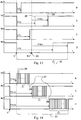
- the device according to the invention remains inactive as long as the variations of the voltage of the network 17 remain within a range of values considered as normal. If the value of the voltage passes above a first threshold 18 and / or the speed of the growth of the value of the voltage exceeds a second threshold, then the power load controlled by the device is supplied. returns below a third threshold 20, which is not necessarily equal to the first, the supply of the power load is cut off 21.
- the device according to the invention remains inactive as long as the variations of the voltage of the network 17 remain within a range of values considered as normal. If the value of the voltage falls below a first threshold 20 and / or the speed of the decay of the value of the voltage exceeds a second threshold, then the supply of the power load controlled by the device is cut off. When the voltage returns above a third threshold 18, which is not necessarily equal to the first threshold, the supply of the power load is restored 19.
- This delay is preferably introduced between the instant of the detection of the disappearance of the anomaly, which is detected synchronously by all the devices in a large part of the network, and the actual change of state of the power loads.
- the changes of state will advantageously be the most out of sync possible to spread power variations facing the power grid as a whole.
- the figure 9 illustrates the behavior of an autonomous variant of the device according to the invention which exploits the value of the frequency of the AC voltage of the network to extract the control setpoint of the power load.
- the device according to the invention remains inactive as long as the variations of the network frequency 22 remain within a range of values considered normal. If the value of the frequency passes above a first threshold 18 and / or the speed of the growth of the value of the frequency exceeds a second threshold then the power load controlled by the device is fed 19. When the frequency returns below a third threshold 20, which is not necessarily equal to the first, the supply of the power load is cut off 21.
- the device according to the invention remains inactive as long as the variations of the voltage of the network 22 remain within a range of values considered as normal. If the value of the frequency falls below a first threshold 20 and / or the speed of the decay of the value of the frequency exceeds a second threshold, then the supply of the power load controlled by the device is cut off 21. When the frequency reverts above a third threshold 18, which is not necessarily equal to the first threshold, the supply of the power load is restored 19.
- the figure 11 illustrates a still more preferred embodiment of the invention wherein the duration of the delay is variable from one device to another.
- This variant introduces an element of individual variability for each device in the duration of the time delay whose expiration conditions the return to the initial state of the power load.
- the initial state being the one before the occurrence of the event that immediately led all the devices concerned to change state synchronously.
- the element of variability is arranged to maximize the differentiation of a device to another between a low limit and a high limit allowing the network manager to know in advance the maximum time windows of each of its actions. It is thus possible to predict, by simulation by means of a mathematical model, the behavior of the network in the event of an anomaly that has led devices to change the state of the power load that they drive autonomously.
- curve a) illustrates the minimum value of the variable delay. This value is determined to nevertheless have an effect on the network and to protect the power load from the possibly harmful effects of too short switching cycles.
- Curve b) illustrates a first timeout value for a given device.
- Curve c) illustrates the delay value specific to the nth device according to the invention present in the network and having detected the same event as those associated with curves a) and b).
- curve d) illustrates the maximum value that the variable delay can take in the context of a given implementation of the invention.
- the duration 23 represents the maximum time excursion of the variable part of the delay.
- the figure 12 illustrates a variant where the variability comes from the environment.
- the two curves a) and b) of the figure 12 illustrate an example of an environment variable that can be used in calculating the timeout value for each device.
- the calculation method used in the program of the microcontroller embodying the invention is arranged so that the result in terms of delay time is framed by a minimum value and a maximum value, that the probability of obtaining the same values is low. and that the individual values are strongly differentiated from each other.
- the duration 23 represents the maximum temporal excursion of the variable portion of the delay as a function of an environment variable.
- temperature is the chosen environment variable because its potential for device-to-device variability is large, and modern microcontrollers that include an analog-to-digital converter typically also include a means for measuring temperature. of the chip. This choice makes it possible to implement this refinement of the invention at a marginal marginal cost outside that of storing the additional code required.
- the figure 13 illustrates a variant where timers are restarted.
- This figure illustrates a functional refinement of the invention that allows the network manager to further spread the power peak if necessary by repeating the transmission of the initial command at carefully chosen times by means of a tool to assist network driving by simulation.
- everything happens as illustrated previously by the figure 11 because their delay expires before receipt of a repeat command 24, or before receiving a specific command to restart the timer if necessary.
- the delays of the devices have not yet expired when the new command 24 is received.
- the refinement of the invention then operates by restarting the delays of these devices alone. This has the effect of spreading more and more the power peak by involving a number of devices that decreases until it is no longer necessary to repeat the command.
- the duration 23 represents the maximum time excursion of the variable part of the delay after extension by the repetition of the commands.
- This functional refinement of the invention increases the flexibility and the possibilities of spreading power peaks without requiring additional means for its implementation and without significantly increasing the traffic on the network.
- the figure 14 illustrates a variant with priority management.
- the devices according to the invention are arranged to manage several levels of priority. Each participating device must know the priority level assigned to it. This can be done during the manufacture of the device or the device that contains it in the case of priorities depending on the use of electricity or the power of the load. In other cases, a local setting of each device, or a remote setting according to the possibilities of the network information transmission system, is necessary.
- the three chronograms a), b) and c) correspond to three levels of priorities managed according to the method of the invention. The method is applicable to any number of priority levels.
- Each priority level is assigned a time range within which all timers of the devices concerned must expire.
- the delays of the devices which are associated with the immediately lower priority level are advantageously increased by a fixed security value 27 to avoid any overlapping phenomenon at the adjacent priority level boundaries, taking into account the drifts and uncertainties in the calculation of the values of the delay.
- a value minimum is also advantageously added at the top of the highest priority level for the reasons explained in the description of the figure 11 .
- This figure also illustrates the management of delays within a time grid whose number and the duration of the elementary steps 28 are predetermined. This functional refinement facilitates the modeling of the behaviors of the system which is an interesting complement of the invention to facilitate its implementation in the context of a deterministic management of the electrical network.
- a temporization occurring in a temporal grid is in no way contradictory with the use of an environment variable or a pseudo-random variable in the computation of the delays, it indicates only that the computed values are discretized before use to fall in the grid steps, the latter being synchronized in all the devices concerned by the initial synchronous event (S).
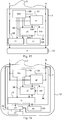
- the figure 15 illustrates a preferred embodiment of the device 1 when the power load is external.
- This variant comprises a low voltage supply subassembly 29 supplying the voltages necessary for the operation of the other subassemblies from the voltage of the electrical network 2 to which it is connected.
- the microcontroller 30 which manages the resources of the device by means of software contained in its program memory, a working RAM, a non-volatile memory for permanent storage of operating parameters. and functional states, and integrated peripherals such as an analog-to-digital converter.
- Models from the Atmel 8bit AVR "tiny" family of microcontrollers, registered trademarks, or models of Texas Instrument's "MSP430" 16bit family of microcontrollers, are particularly suitable, but this type of common electronic component also exists. at other semiconductor manufacturers.
- An analog front end 31 formats, and if necessary pre-filter, the signals from the electrical voltage of the installation before converting them in the microcontroller to be able to perform the appropriate digital processing.
- a power interface 32 comprising a relay and its control electronics ensures a functional link to be the corresponding logic output of the microcontroller and the power load to be controlled.
- a user interface 33 comprising at least one push button and a led diode provides communication between the device and the user.
- the optional subassembly 34 represents a low-voltage carrier modem or a radio transmitter according to the characteristics of the transmission means used by the electricity distributor for the management of its network. Where possible, it will be preferred to use only the receiving portions of the modems and transmitters.
- the figure 16 illustrates another preferred embodiment of the device when it is integrated within an apparatus 12 comprising at least one power load.
- the figure 16 differs from the previous one in that the device according to the invention 1 is integrated in an apparatus of which it uses the power control means 15 of the at least one power load and the interface means with the user 33 which are often more user-friendly in a sophisticated device than the simple button and led provided in the basic version of the device according to the invention.
Landscapes
- Engineering & Computer Science (AREA)
- Power Engineering (AREA)
- Physics & Mathematics (AREA)
- General Physics & Mathematics (AREA)
- Automation & Control Theory (AREA)
- Remote Monitoring And Control Of Power-Distribution Networks (AREA)
Claims (17)
- Vorrichtung (1) zur Steuerung einer Stromlast (12) in einer Elektroinstallation im Endverteilerstadium (2) in Abhängigkeit von den Ereignissen im Zusammenhang mit der Funktionsweise oder der Steuerung eines Stromverteilernetz (16), die dadurch gekennzeichnet ist, dass sie:- mindestens einen funktionalen Block umfasst, der die ersten Mittel (3, 8, 10) bildet, um mindestens einen Fernsteuerbefehl zu empfangen;- mindestens einen funktionalen Block (7, 3, 8) umfasst, der die Spannung der Elektroinstallation im Endverteilerstadium auswertet, um mindestens eine autonome Information aus dem Wert der Spannung der Elektroinstallation im Endverteilerstadium und/oder ihrer Entwicklung im Zeitverlauf und/oder aus dem Wert der Frequenz der Wechselspannung der Elektroinstallation im Endverteilerstadium und/oder ihrer Entwicklung im Zeitverlauf auszulesen, und/oder um mindestens einen Fernsteuerbefehl per Tonfrequenz-Rundsteueranlage oder per Trägerfrequenzanlage zu empfangen, mindestens den einen funktionalen Block, der die Spannung der Elektroinstallation im Endverteilerstadium ausliest, was dann die sekundären Mittel (3, 8) bildet, um mindestens einen Fernsteuerbefehl zu empfangen;- einen funktionalen Block (4), der den funktionalen Zustand der genannten gesteuerten Stromlast (12) festlegt in Abhängigkeit des mindestens einen empfangenen Fernsteuerbefehls und/oder der mindestens einen ausgelesenen autonomen Information und/oder einem Befehl des Benutzers.
- Vorrichtung nach Anspruch 1, die dadurch gekennzeichnet ist, dass sie des Weiteren Mittel (5) für das Umschalten der Stromversorgung (6) der zu steuernden Stromlast (12) umfasst.
- Vorrichtung nach Anspruch 1, die dadurch gekennzeichnet ist, dass sie des Weiteren Mittel (11) zur Fernsteuerung der Funktionsweise einer in einem Gerät (12) integrierten Stromlast umfasst, das fernsteuerbar ist.
- Vorrichtung nach einem der vorgenannten Ansprüche, die dadurch gekennzeichnet ist, dass der Empfang mindestens eines ersten Fernsteuerbefehls und/oder das Auslesen einer ersten autonomen Information die Stromlast in einen funktionalen Zustand versetzt, der für eine unbestimmte Dauer festgelegt wird, das Versetzen der Stromlast in einen anderen funktionalen Zustand bedarf des Empfangs mindestens eines zweiten Fernsteuerbefehls und/oder des Auslesens einer zweiten autonomen Information, die mit diesem anderen funktionalen Zustand verknüpft ist.
- Vorrichtung nach einem der vorgenannten Ansprüche, die dadurch gekennzeichnet ist, dass mindestens eine Änderung des funktionalen Zustands der Stromlast auf den Ablauf einer Zeitverzögerung folgt.
- Vorrichtung nach Anspruch 5, die dadurch gekennzeichnet ist, dass sich die Dauer der Zeitverzögerung in einem zeitlichen Raster befindet, in dem Anzahl und Dauer der Grundschritte vorbestimmt sind.
- Vorrichtung nach einem der Ansprüche 5 oder 6, die dadurch gekennzeichnet ist, dass die Zeitverzögerung mindestens einen für jede Vorrichtung variablen Bereich umfasst.
- Vorrichtung nach Anspruch 7, die dadurch gekennzeichnet ist, dass der variable Bereich der Zeitverzögerung mindestens teilweise im Rahmen einer Prioritätssteuerung für den Zugriff auf die elektrische Leistung verwendet wird.
- Vorrichtung nach einem der Ansprüche 5 bis 8, die dadurch gekennzeichnet ist, dass die Dauer der gesamten oder teilweisen Zeitverzögerung durch den Empfang mindestens eines zweiten Fernsteuerbefehls innerhalb eines Zeitraums einer vorbestimmten Dauer verändert wird, die ab dem Empfang eines ersten Fernsteuerbefehls berechnet wird.
- Vorrichtung nach einem der Ansprüche 5 bis 9, die dadurch gekennzeichnet ist, dass der Empfang eines Fernsteuerbefehls die nicht abgelaufenen Zeitverzögerungen neu initiiert, die Vorrichtungen, deren Zeitverzögerung abgelaufen ist, reagieren während einer vorbestimmten Dauer nicht auf jedweden neuen Empfang eines Fernsteuerbefehls.
- Vorrichtung nach einem der vorgenannten Ansprüche, die dadurch gekennzeichnet ist, dass sie des Weiteren Steuermittel (13, 14) umfasst, um dem Benutzer die Möglichkeit zu geben, der von der genannten Vorrichtung gesteuerten Stromlast mindestens einen funktionalen Zustand aufzuzwingen und/oder mindestens vorübergehend jede automatische Änderung des zumindest einen funktionalen Zustands zu hemmen.
- System zur Steuerung eines Stromverteilernetzes, das dadurch gekennzeichnet ist, dass es:- eine Vielzahl von Vorrichtungen umfasst nach einem der Ansprüche 1 bis 11 zur Steuerung der Funktionsweise einer Stromlast in einer Elektroinstallation im Endverteilerstadium in Abhängigkeit von Ereignissen im Zusammenhang mit der Funktionsweise oder der Steuerung eines Stromverteilernetzes;- ein Stromverteilernetz umfasst, an das die genannte Elektroinstallation im Endverteilerstadium angeschlossen ist und deren Spannung am Anschlusspunkt geeignet ist, den Empfang mindestens eines Fernsteuerbefehls und/oder das Auslesen mindestens einer autonomen Information in jeder der genannten Vorrichtungen zu ermöglichen.
- System nach Anspruch 12, das dadurch gekennzeichnet ist, dass es des Weiteren mindestens eine Steuerungssoftware umfasst, die auf der Modellierung des Verhaltens der Vorrichtungen innerhalb des Stromnetzes basiert zur Unterstützung der Steuerung des Netzes und/oder im Rahmen einer automatisierten Steuerung des Stromverteilernetzes.
- Verfahren zur Steuerung eines Stromverteilernetzes, das speziell für die Verwendung einer Vielzahl von Vorrichtungen ausgelegt wurde nach einem der Ansprüche 1 bis 11, und das dadurch gekennzeichnet ist, dass es Schritte umfasst, in denen:- Man mindestens einen Fernsteuerbefehl empfängt und/oder mindestens eine autonome Information aus der Spannung der Elektroinstallation im Endverteilerstadium ausliest;- Man den funktionalen Zustand der Stromlast in Abhängigkeit des mindestens einen empfangenen Fernsteuerbefehls und/oder der mindestens einen ausgelesenen autonomen Information ändert;- Man dem Benutzer die Möglichkeit bietet, der von der genannten Vorrichtung gesteuerten Stromlast mindestens einen funktionalen Zustand aufzuzwingen und/oder mindestens vorübergehend jede automatische Änderung des zumindest einen funktionalen Zustands zu hemmen.
- Verfahren nach Anspruch 14, das dadurch gekennzeichnet ist, dass es des Weiteren einen Schritt der Desynchronisation mindestens einer Änderung eines funktionalen Zustands einer von einer Vorrichtung gesteuerten Stromlast umfasst in Bezug auf die Änderungen eines funktionalen Zustands mindestens einer anderen von mindestens einer anderen Vorrichtung gesteuerten Stromlast innerhalb des gleichen Stromnetzes, was zu einer ähnlichen Wirkung hinsichtlich der beanspruchten Leistung im Stromnetz führt.
- Verfahren nach einem der Ansprüche 14 oder 15, das dadurch gekennzeichnet ist, dass es des Weiteren mindestens einen Schritt für die Implementierung mindestens einer Steuerungssoftware umfasst, die auf der Modellierung des Verhaltens der genannten Vorrichtungen innerhalb des Stromnetzes basiert zur Unterstützung der Steuerung des Netzes und/oder im Rahmen einer automatisierten Steuerung des Stromverteilernetzes.
- Verwendung des Verfahrens nach einem der Ansprüche 14 bis 16, um jederzeit das Gleichgewicht zwischen der produzierten Leistung und der verbrauchten Leistung in einem Stromnetz zu gewährleisten, indem durch angemessene Steuerung einer Vielzahl von Stromlasten auf den Verbrauch hingewirkt wird.
Applications Claiming Priority (2)
| Application Number | Priority Date | Filing Date | Title |
|---|---|---|---|
| FR1301618A FR3008249B1 (fr) | 2013-07-08 | 2013-07-08 | Dispositif pour piloter le fonctionnement d'une charge de puissance dans un reseau electrique, procede et systeme associes |
| PCT/IB2014/062632 WO2015004557A1 (fr) | 2013-07-08 | 2014-06-26 | Dispositif pour piloter une charge de puissance dans un reseau electrique procede et systeme associes |
Publications (2)
| Publication Number | Publication Date |
|---|---|
| EP3020113A1 EP3020113A1 (de) | 2016-05-18 |
| EP3020113B1 true EP3020113B1 (de) | 2017-05-10 |
Family
ID=50478424
Family Applications (1)
| Application Number | Title | Priority Date | Filing Date |
|---|---|---|---|
| EP14744377.4A Active EP3020113B1 (de) | 2013-07-08 | 2014-06-26 | Vorrichtung zur steuerung einer stromlast in einem elektrischen netz und zugehöriges verfahren und system |
Country Status (6)
| Country | Link |
|---|---|
| US (1) | US10199827B2 (de) |
| EP (1) | EP3020113B1 (de) |
| CN (1) | CN105359368B (de) |
| ES (1) | ES2628487T3 (de) |
| FR (1) | FR3008249B1 (de) |
| WO (1) | WO2015004557A1 (de) |
Families Citing this family (7)
| Publication number | Priority date | Publication date | Assignee | Title |
|---|---|---|---|---|
| FR3054735B1 (fr) * | 2016-07-28 | 2018-08-17 | Peugeot Citroen Automobiles Sa | Dispositif de protection et commutation electrique d’un equipement electronique, a controle des etats de moyens de commutation |
| CN106469941A (zh) * | 2016-11-17 | 2017-03-01 | 贵州电网有限责任公司贵阳供电局 | 适用于小水电富集区域的广域备自投系统智能控制方法 |
| US20220181877A1 (en) * | 2019-02-14 | 2022-06-09 | Massachusetts Institute Of Technology | Voltage waveform transient identification and autonomous load coordination |
| US11133679B2 (en) * | 2019-02-27 | 2021-09-28 | General Electric Company | System and method for operating a hybrid energy facility having multiple power sources |
| FR3105886B1 (fr) * | 2019-12-28 | 2021-11-19 | Ergylink | Appareil électrique de puissance pilotable par un automatisme externe, système et procédé associés |
| WO2021136573A1 (fr) * | 2019-12-30 | 2021-07-08 | Adjila Abderrahmane | Connecteur électrique contrôlé par sms |
| CN113796344B (zh) * | 2021-09-16 | 2022-11-25 | 深圳市翌卡本智能科技有限公司 | 一种新型变频智能增氧机调速控制系统 |
Family Cites Families (12)
| Publication number | Priority date | Publication date | Assignee | Title |
|---|---|---|---|---|
| FR2468240B1 (fr) * | 1979-10-24 | 1986-02-21 | Enertec | Relais de telecommande |
| CH676050A5 (de) | 1988-09-08 | 1990-11-30 | Landis & Gyr Betriebs Ag | |
| FR2822303B1 (fr) * | 2001-03-15 | 2003-06-27 | Electricite De France | Prise d'alimentation electrique programmable en fonction d'ordres tarifaires |
| CN100338846C (zh) * | 2005-06-22 | 2007-09-19 | 肖冬冰 | 农村低压配电网自动化监控装置及其方法 |
| AU2005239620B2 (en) * | 2005-11-28 | 2011-04-28 | Enermet Ag | Control apparatus for deactivating an electrical load during congestion periods |
| US8271147B2 (en) | 2009-02-26 | 2012-09-18 | Massachusetts Institute Of Technology | Methods and apparatus for energy demand management |
| FR2947396B1 (fr) | 2009-06-29 | 2013-07-05 | Delta Dore | Procede et dispositif d'effacement et d'anticipation de la consommation electrique chez des abonnes |
| FR2948831B1 (fr) * | 2009-07-31 | 2022-01-28 | Jerome Gilbert | Systeme universel pour recharger au moins un appareil portable |
| US9197949B2 (en) * | 2010-12-02 | 2015-11-24 | Tenrehte Technologies, Inc. | Self-organizing multiple appliance network connectivity apparatus for controlling plurality of appliances |
| FR2976415B1 (fr) | 2011-06-10 | 2013-07-05 | Electricite De France | Ensemble de pilotage d'un systeme de production/consommation electrique |
| EP2798786B1 (de) * | 2011-12-28 | 2018-02-28 | Lutron Electronics Company, Inc. | Lastensteuerungssystem mit einer rundfunksteuerung mit einem verteilten drahtlosen kommunikationssystem |
| US9736911B2 (en) * | 2012-01-17 | 2017-08-15 | Lutron Electronics Co. Inc. | Digital load control system providing power and communication via existing power wiring |
-
2013
- 2013-07-08 FR FR1301618A patent/FR3008249B1/fr not_active Expired - Fee Related
-
2014
- 2014-06-26 ES ES14744377.4T patent/ES2628487T3/es active Active
- 2014-06-26 WO PCT/IB2014/062632 patent/WO2015004557A1/fr not_active Ceased
- 2014-06-26 EP EP14744377.4A patent/EP3020113B1/de active Active
- 2014-06-26 CN CN201480039026.5A patent/CN105359368B/zh active Active
- 2014-06-26 US US14/903,499 patent/US10199827B2/en active Active
Also Published As
| Publication number | Publication date |
|---|---|
| ES2628487T3 (es) | 2017-08-03 |
| FR3008249A1 (fr) | 2015-01-09 |
| US20160149410A1 (en) | 2016-05-26 |
| CN105359368A (zh) | 2016-02-24 |
| WO2015004557A1 (fr) | 2015-01-15 |
| FR3008249B1 (fr) | 2017-04-21 |
| US10199827B2 (en) | 2019-02-05 |
| EP3020113A1 (de) | 2016-05-18 |
| CN105359368B (zh) | 2018-07-10 |
Similar Documents
| Publication | Publication Date | Title |
|---|---|---|
| WO2015004557A1 (fr) | Dispositif pour piloter une charge de puissance dans un reseau electrique procede et systeme associes | |
| EP1873615B1 (de) | Vorrichtung zur Einsparung des Standby-Verbrauchs einer Geräteanordnung | |
| EP2718975B1 (de) | Vorrichtung zur erzeugung von fotovoltaischer energie mit individueller zellenverwaltung | |
| US8427006B2 (en) | Device for disconnecting at least one appliance from the electrical mains, which provides at least one override operating mode, a configurable device, system and configuration method | |
| WO2016087781A1 (fr) | Procédé pour la gestion d'énergie | |
| FR3009768A1 (fr) | Dispositif pout piloter le fonctionnement d'une charge de puissance a partir d'un information issue d'un compteur electrique, procede et systeme associes | |
| EP2460364B1 (de) | Modul zur verwaltung von laternenmasten und diensten sowie fernverwaltungssystem mit mindestens einem solchen modul | |
| WO2016071599A1 (fr) | Point de connexion electrique monte dans une paroi murale dans un logement et installation electrique comportant au moins un tel point de connexion | |
| EP3361602B1 (de) | Elektronische untereinheit, die einen sichtbaren null-energieverbrauch im stand-by-betrieb oder beim ausschalten hat, entsprechendes system und verfahren | |
| US20210263578A1 (en) | Photovoltaic smart power distribution box and controller | |
| WO2016142628A1 (fr) | Carte électronique de pilotage énergétique d'un équipement électrique autonome et communicant | |
| FR3050883B1 (fr) | Dispositif et procede pour recevoir des telecommandes transpises par au moins deux canaux independants dans un reseau electrique | |
| FR3002642A1 (fr) | Systeme de mesure d'energie bidirectionnel. | |
| EP1672810A1 (de) | Elektrische Speisungssteuerungsvorrichtung für Elektrogeräte, insbesondere Lampen für eine öffentliche Beleuchtung. | |
| FR2822303A1 (fr) | Prise d'alimentation electrique programmable en fonction d'ordres tarifaires | |
| FR3105886A1 (fr) | Appareil électrique de puissance pilotable par un automatisme externe, système et procédé associés | |
| Naik et al. | Improvisation of smart home automation using hybrid sources | |
| EP2312598A1 (de) | Verfahren und Vorrichtung zur Steuerung eines elektromagnetischen Relais | |
| FR2956534A1 (fr) | Dispositif de maintien de l'alimentation d'un appareil electrique raccorde a un reseau electrique fonctionnant selon des periodes tarifaires par contacteur ou programmateur | |
| FR3077696A1 (fr) | Dispositif pour remplacer une liaison filaire entre un compteur d’energie et au moins un appareil electronique par une liaison sans fil, procede associe | |
| FR3012646A1 (fr) | Procede d'optimisation de la consommation et de la production d'une installation electrique | |
| FR3142620A1 (fr) | Armoire electrique connectee | |
| EP4302378A1 (de) | Verfahren und vorrichtung zur steuerung eines stromnetzes | |
| EP2533391A2 (de) | Multi-Source-Steuerungssystem von Stromgeneratoren | |
| FR2989231A1 (fr) | Prise et procede de controle d'une installation electrique comprenant une telle prise |
Legal Events
| Date | Code | Title | Description |
|---|---|---|---|
| PUAI | Public reference made under article 153(3) epc to a published international application that has entered the european phase |
Free format text: ORIGINAL CODE: 0009012 |
|
| 17P | Request for examination filed |
Effective date: 20160112 |
|
| AK | Designated contracting states |
Kind code of ref document: A1 Designated state(s): AL AT BE BG CH CY CZ DE DK EE ES FI FR GB GR HR HU IE IS IT LI LT LU LV MC MK MT NL NO PL PT RO RS SE SI SK SM TR |
|
| AX | Request for extension of the european patent |
Extension state: BA ME |
|
| DAX | Request for extension of the european patent (deleted) | ||
| REG | Reference to a national code |
Ref country code: DE Ref legal event code: R079 Ref document number: 602014009751 Country of ref document: DE Free format text: PREVIOUS MAIN CLASS: H02J0003140000 Ipc: H02J0003000000 |
|
| GRAP | Despatch of communication of intention to grant a patent |
Free format text: ORIGINAL CODE: EPIDOSNIGR1 |
|
| RIC1 | Information provided on ipc code assigned before grant |
Ipc: H02J 3/00 20060101AFI20161116BHEP |
|
| INTG | Intention to grant announced |
Effective date: 20161201 |
|
| GRAS | Grant fee paid |
Free format text: ORIGINAL CODE: EPIDOSNIGR3 |
|
| GRAA | (expected) grant |
Free format text: ORIGINAL CODE: 0009210 |
|
| AK | Designated contracting states |
Kind code of ref document: B1 Designated state(s): AL AT BE BG CH CY CZ DE DK EE ES FI FR GB GR HR HU IE IS IT LI LT LU LV MC MK MT NL NO PL PT RO RS SE SI SK SM TR |
|
| REG | Reference to a national code |
Ref country code: GB Ref legal event code: FG4D Free format text: NOT ENGLISH |
|
| REG | Reference to a national code |
Ref country code: AT Ref legal event code: REF Ref document number: 893257 Country of ref document: AT Kind code of ref document: T Effective date: 20170515 Ref country code: CH Ref legal event code: EP |
|
| REG | Reference to a national code |
Ref country code: IE Ref legal event code: FG4D Free format text: LANGUAGE OF EP DOCUMENT: FRENCH |
|
| REG | Reference to a national code |
Ref country code: DE Ref legal event code: R084 Ref document number: 602014009751 Country of ref document: DE |
|
| REG | Reference to a national code |
Ref country code: DE Ref legal event code: R096 Ref document number: 602014009751 Country of ref document: DE |
|
| REG | Reference to a national code |
Ref country code: ES Ref legal event code: FG2A Ref document number: 2628487 Country of ref document: ES Kind code of ref document: T3 Effective date: 20170803 |
|
| REG | Reference to a national code |
Ref country code: NL Ref legal event code: MP Effective date: 20170510 |
|
| REG | Reference to a national code |
Ref country code: LT Ref legal event code: MG4D |
|
| REG | Reference to a national code |
Ref country code: FR Ref legal event code: PLFP Year of fee payment: 4 |
|
| REG | Reference to a national code |
Ref country code: AT Ref legal event code: MK05 Ref document number: 893257 Country of ref document: AT Kind code of ref document: T Effective date: 20170510 |
|
| PG25 | Lapsed in a contracting state [announced via postgrant information from national office to epo] |
Ref country code: GR Free format text: LAPSE BECAUSE OF FAILURE TO SUBMIT A TRANSLATION OF THE DESCRIPTION OR TO PAY THE FEE WITHIN THE PRESCRIBED TIME-LIMIT Effective date: 20170811 Ref country code: LT Free format text: LAPSE BECAUSE OF FAILURE TO SUBMIT A TRANSLATION OF THE DESCRIPTION OR TO PAY THE FEE WITHIN THE PRESCRIBED TIME-LIMIT Effective date: 20170510 Ref country code: FI Free format text: LAPSE BECAUSE OF FAILURE TO SUBMIT A TRANSLATION OF THE DESCRIPTION OR TO PAY THE FEE WITHIN THE PRESCRIBED TIME-LIMIT Effective date: 20170510 Ref country code: AT Free format text: LAPSE BECAUSE OF FAILURE TO SUBMIT A TRANSLATION OF THE DESCRIPTION OR TO PAY THE FEE WITHIN THE PRESCRIBED TIME-LIMIT Effective date: 20170510 Ref country code: NO Free format text: LAPSE BECAUSE OF FAILURE TO SUBMIT A TRANSLATION OF THE DESCRIPTION OR TO PAY THE FEE WITHIN THE PRESCRIBED TIME-LIMIT Effective date: 20170810 Ref country code: HR Free format text: LAPSE BECAUSE OF FAILURE TO SUBMIT A TRANSLATION OF THE DESCRIPTION OR TO PAY THE FEE WITHIN THE PRESCRIBED TIME-LIMIT Effective date: 20170510 |
|
| PG25 | Lapsed in a contracting state [announced via postgrant information from national office to epo] |
Ref country code: NL Free format text: LAPSE BECAUSE OF FAILURE TO SUBMIT A TRANSLATION OF THE DESCRIPTION OR TO PAY THE FEE WITHIN THE PRESCRIBED TIME-LIMIT Effective date: 20170510 Ref country code: PL Free format text: LAPSE BECAUSE OF FAILURE TO SUBMIT A TRANSLATION OF THE DESCRIPTION OR TO PAY THE FEE WITHIN THE PRESCRIBED TIME-LIMIT Effective date: 20170510 Ref country code: IS Free format text: LAPSE BECAUSE OF FAILURE TO SUBMIT A TRANSLATION OF THE DESCRIPTION OR TO PAY THE FEE WITHIN THE PRESCRIBED TIME-LIMIT Effective date: 20170910 Ref country code: RS Free format text: LAPSE BECAUSE OF FAILURE TO SUBMIT A TRANSLATION OF THE DESCRIPTION OR TO PAY THE FEE WITHIN THE PRESCRIBED TIME-LIMIT Effective date: 20170510 Ref country code: BG Free format text: LAPSE BECAUSE OF FAILURE TO SUBMIT A TRANSLATION OF THE DESCRIPTION OR TO PAY THE FEE WITHIN THE PRESCRIBED TIME-LIMIT Effective date: 20170810 Ref country code: SE Free format text: LAPSE BECAUSE OF FAILURE TO SUBMIT A TRANSLATION OF THE DESCRIPTION OR TO PAY THE FEE WITHIN THE PRESCRIBED TIME-LIMIT Effective date: 20170510 Ref country code: LV Free format text: LAPSE BECAUSE OF FAILURE TO SUBMIT A TRANSLATION OF THE DESCRIPTION OR TO PAY THE FEE WITHIN THE PRESCRIBED TIME-LIMIT Effective date: 20170510 |
|
| PG25 | Lapsed in a contracting state [announced via postgrant information from national office to epo] |
Ref country code: CZ Free format text: LAPSE BECAUSE OF FAILURE TO SUBMIT A TRANSLATION OF THE DESCRIPTION OR TO PAY THE FEE WITHIN THE PRESCRIBED TIME-LIMIT Effective date: 20170510 Ref country code: EE Free format text: LAPSE BECAUSE OF FAILURE TO SUBMIT A TRANSLATION OF THE DESCRIPTION OR TO PAY THE FEE WITHIN THE PRESCRIBED TIME-LIMIT Effective date: 20170510 Ref country code: SK Free format text: LAPSE BECAUSE OF FAILURE TO SUBMIT A TRANSLATION OF THE DESCRIPTION OR TO PAY THE FEE WITHIN THE PRESCRIBED TIME-LIMIT Effective date: 20170510 Ref country code: RO Free format text: LAPSE BECAUSE OF FAILURE TO SUBMIT A TRANSLATION OF THE DESCRIPTION OR TO PAY THE FEE WITHIN THE PRESCRIBED TIME-LIMIT Effective date: 20170510 Ref country code: DK Free format text: LAPSE BECAUSE OF FAILURE TO SUBMIT A TRANSLATION OF THE DESCRIPTION OR TO PAY THE FEE WITHIN THE PRESCRIBED TIME-LIMIT Effective date: 20170510 |
|
| REG | Reference to a national code |
Ref country code: DE Ref legal event code: R097 Ref document number: 602014009751 Country of ref document: DE |
|
| PG25 | Lapsed in a contracting state [announced via postgrant information from national office to epo] |
Ref country code: SM Free format text: LAPSE BECAUSE OF FAILURE TO SUBMIT A TRANSLATION OF THE DESCRIPTION OR TO PAY THE FEE WITHIN THE PRESCRIBED TIME-LIMIT Effective date: 20170510 |
|
| PLBE | No opposition filed within time limit |
Free format text: ORIGINAL CODE: 0009261 |
|
| STAA | Information on the status of an ep patent application or granted ep patent |
Free format text: STATUS: NO OPPOSITION FILED WITHIN TIME LIMIT |
|
| REG | Reference to a national code |
Ref country code: IE Ref legal event code: MM4A |
|
| 26N | No opposition filed |
Effective date: 20180213 |
|
| PG25 | Lapsed in a contracting state [announced via postgrant information from national office to epo] |
Ref country code: LU Free format text: LAPSE BECAUSE OF NON-PAYMENT OF DUE FEES Effective date: 20170626 Ref country code: IE Free format text: LAPSE BECAUSE OF NON-PAYMENT OF DUE FEES Effective date: 20170626 |
|
| REG | Reference to a national code |
Ref country code: FR Ref legal event code: PLFP Year of fee payment: 5 |
|
| PG25 | Lapsed in a contracting state [announced via postgrant information from national office to epo] |
Ref country code: SI Free format text: LAPSE BECAUSE OF FAILURE TO SUBMIT A TRANSLATION OF THE DESCRIPTION OR TO PAY THE FEE WITHIN THE PRESCRIBED TIME-LIMIT Effective date: 20170510 |
|
| REG | Reference to a national code |
Ref country code: ES Ref legal event code: GC2A Effective date: 20180709 |
|
| PG25 | Lapsed in a contracting state [announced via postgrant information from national office to epo] |
Ref country code: MT Free format text: LAPSE BECAUSE OF FAILURE TO SUBMIT A TRANSLATION OF THE DESCRIPTION OR TO PAY THE FEE WITHIN THE PRESCRIBED TIME-LIMIT Effective date: 20170510 |
|
| PG25 | Lapsed in a contracting state [announced via postgrant information from national office to epo] |
Ref country code: HU Free format text: LAPSE BECAUSE OF FAILURE TO SUBMIT A TRANSLATION OF THE DESCRIPTION OR TO PAY THE FEE WITHIN THE PRESCRIBED TIME-LIMIT; INVALID AB INITIO Effective date: 20140626 Ref country code: MC Free format text: LAPSE BECAUSE OF FAILURE TO SUBMIT A TRANSLATION OF THE DESCRIPTION OR TO PAY THE FEE WITHIN THE PRESCRIBED TIME-LIMIT Effective date: 20170510 |
|
| PG25 | Lapsed in a contracting state [announced via postgrant information from national office to epo] |
Ref country code: CY Free format text: LAPSE BECAUSE OF FAILURE TO SUBMIT A TRANSLATION OF THE DESCRIPTION OR TO PAY THE FEE WITHIN THE PRESCRIBED TIME-LIMIT Effective date: 20170510 |
|
| PG25 | Lapsed in a contracting state [announced via postgrant information from national office to epo] |
Ref country code: MK Free format text: LAPSE BECAUSE OF FAILURE TO SUBMIT A TRANSLATION OF THE DESCRIPTION OR TO PAY THE FEE WITHIN THE PRESCRIBED TIME-LIMIT Effective date: 20170510 |
|
| PG25 | Lapsed in a contracting state [announced via postgrant information from national office to epo] |
Ref country code: TR Free format text: LAPSE BECAUSE OF FAILURE TO SUBMIT A TRANSLATION OF THE DESCRIPTION OR TO PAY THE FEE WITHIN THE PRESCRIBED TIME-LIMIT Effective date: 20170510 |
|
| PG25 | Lapsed in a contracting state [announced via postgrant information from national office to epo] |
Ref country code: PT Free format text: LAPSE BECAUSE OF FAILURE TO SUBMIT A TRANSLATION OF THE DESCRIPTION OR TO PAY THE FEE WITHIN THE PRESCRIBED TIME-LIMIT Effective date: 20170510 |
|
| PG25 | Lapsed in a contracting state [announced via postgrant information from national office to epo] |
Ref country code: AL Free format text: LAPSE BECAUSE OF FAILURE TO SUBMIT A TRANSLATION OF THE DESCRIPTION OR TO PAY THE FEE WITHIN THE PRESCRIBED TIME-LIMIT Effective date: 20170510 |
|
| PGFP | Annual fee paid to national office [announced via postgrant information from national office to epo] |
Ref country code: ES Payment date: 20250715 Year of fee payment: 12 |
|
| PGFP | Annual fee paid to national office [announced via postgrant information from national office to epo] |
Ref country code: CH Payment date: 20250701 Year of fee payment: 12 |
|
| REG | Reference to a national code |
Ref country code: CH Ref legal event code: U11 Free format text: ST27 STATUS EVENT CODE: U-0-0-U10-U11 (AS PROVIDED BY THE NATIONAL OFFICE) Effective date: 20260701 |
|
| PGFP | Annual fee paid to national office [announced via postgrant information from national office to epo] |
Ref country code: GB Payment date: 20260607 Year of fee payment: 13 |
|
| PGFP | Annual fee paid to national office [announced via postgrant information from national office to epo] |
Ref country code: IT Payment date: 20260619 Year of fee payment: 13 |
|
| PGFP | Annual fee paid to national office [announced via postgrant information from national office to epo] |
Ref country code: DE Payment date: 20260609 Year of fee payment: 13 |
|
| PGFP | Annual fee paid to national office [announced via postgrant information from national office to epo] |
Ref country code: BE Payment date: 20260609 Year of fee payment: 13 |
|
| PGFP | Annual fee paid to national office [announced via postgrant information from national office to epo] |
Ref country code: FR Payment date: 20260607 Year of fee payment: 13 |