EP3020271B1 - Stallanlage - Google Patents
Stallanlage Download PDFInfo
- Publication number
- EP3020271B1 EP3020271B1 EP15193596.2A EP15193596A EP3020271B1 EP 3020271 B1 EP3020271 B1 EP 3020271B1 EP 15193596 A EP15193596 A EP 15193596A EP 3020271 B1 EP3020271 B1 EP 3020271B1
- Authority
- EP
- European Patent Office
- Prior art keywords
- box
- facility according
- housing facility
- area
- livestock housing
- Prior art date
- Legal status (The legal status is an assumption and is not a legal conclusion. Google has not performed a legal analysis and makes no representation as to the accuracy of the status listed.)
- Active
Links
Images


Classifications
-
- A—HUMAN NECESSITIES
- A01—AGRICULTURE; FORESTRY; ANIMAL HUSBANDRY; HUNTING; TRAPPING; FISHING
- A01K—ANIMAL HUSBANDRY; AVICULTURE; APICULTURE; PISCICULTURE; FISHING; REARING OR BREEDING ANIMALS, NOT OTHERWISE PROVIDED FOR; NEW BREEDS OF ANIMALS
- A01K1/00—Housing animals; Equipment therefor
-
- A—HUMAN NECESSITIES
- A01—AGRICULTURE; FORESTRY; ANIMAL HUSBANDRY; HUNTING; TRAPPING; FISHING
- A01K—ANIMAL HUSBANDRY; AVICULTURE; APICULTURE; PISCICULTURE; FISHING; REARING OR BREEDING ANIMALS, NOT OTHERWISE PROVIDED FOR; NEW BREEDS OF ANIMALS
- A01K1/00—Housing animals; Equipment therefor
- A01K1/0005—Stable partitions
- A01K1/0011—Cubicle partitions
-
- A—HUMAN NECESSITIES
- A01—AGRICULTURE; FORESTRY; ANIMAL HUSBANDRY; HUNTING; TRAPPING; FISHING
- A01K—ANIMAL HUSBANDRY; AVICULTURE; APICULTURE; PISCICULTURE; FISHING; REARING OR BREEDING ANIMALS, NOT OTHERWISE PROVIDED FOR; NEW BREEDS OF ANIMALS
- A01K1/00—Housing animals; Equipment therefor
- A01K1/02—Pigsties; Dog-kennels; Rabbit-hutches or the like
- A01K1/0209—Feeding pens for pigs or cattle
Definitions
- the invention relates to a barn with a first area and a second area in which animals can stay, wherein the second area is associated with a box that is open on at least one side, so that animals can get into the box.
- Such a stable system can be used in particular for calf rearing.
- the box forms a narrow demarcated area, which creates a kind of feeling of security compared to an open, spacious stable.
- the box may in particular be a so-called Principalraumiglu.
- the stables (also referred to as "calf village”) has different climatic zones, which can be visited by the animals as needed. This increases the well-being and health of the animals.
- the object of the invention is to improve a stable system to the effect that the cost of cleaning the box is reduced.
- the box is a self-stable box with side walls and roof and that the box is adjustably mounted so that it from a normal position in which it delimits the second area in a Cleaning position can be brought, in which a free access to the second Range is possible.
- the invention is based on the idea of "out of the way" the box with little effort, so that the second area without affecting walls, ceilings, etc. is accessible. This results in a guaranteed working efficiency through the possibility of one-man management.
- the fact that the box is an inherently stable Panraumiglu with side walls and roof, such a box can be placed in the manner of a prefabricated box or hut with little effort. However, once brought into the cleaning position, the second area can be easily cleaned.
- the box is mounted on a frame.
- the frame gives the box the desired stability so that it can be moved from the normal position to the cleaning position without excessive loads on the box.
- the box in the vertical direction between the normal position and the cleaning position is adjustable.
- the box is lifted, for example by means of a cable upwards, so that bedding, manure, etc. can be cleared from the second area without the walls of the box in the way.
- an anchorage for the box with which this is fixed when it is lowered back to the normal position.
- Such anchoring may consist, for example, of rails or ground anchoring points.
- the box is pivotable about a joint between the normal position and the cleaning position.
- the joint provides for the fixation of the box in both the normal and in the cleaning position.
- the box could also be adjusted by hand from the normal to the cleaning position.
- a drive device is provided, with which the box can be adjusted from the normal position to the cleaning position. This increases the ease of use.
- the drive position includes a cable system with which the box are raised can to bring them from the normal to the cleaning position.
- a cable system is inexpensive, can be flexibly mounted and has a long service life.
- the cable system attacks at two points apart on the box, so that it can be reset by means of the cable system from the cleaning position to the normal position.
- a water collecting channel can be provided, with which also dirty water can be collected, which is obtained when cleaning the box.
- the dirty water can be suitably collected in the same manner as manure, which is obtained in the boxes, and forwarded to a collection container.
- the first area is located within a hall and the second area outside the hall.
- the boxes are used to increase the rearing area by being grown on the outside of the hall to this.
- the small boxes may be calf igloos for individual housing, in which young animals of an age of a few days to a few weeks are reared separately from older animals.
- the hall can be equipped with air conditioning. It is also possible to aerate the hall via the natural ventilation of the curtains. This ensures that in the hall at all times the optimal rearing conditions prevail. In particular, the appropriate ventilation within the hall results in different climatic zones.
- a separating grid is provided with which the first can be separated from the second region. This divider prevents in particular that animals enter the area of the boxes when they are in the cleaning position.
- a plurality of boxes are provided, which are arranged side by side and can be adjusted simultaneously from the normal to the cleaning position. This increases the rationalization effect, since there is a very large second area, which, when all the boxes are in the cleaning position, can be cleaned very efficiently, for example by a tractor with a bucket through the "alley" between the hall and in the Passing boxes located cleaning position and pushes away there litter located there or the manure located there.
- a stable 10 can be seen. It is used in particular for the rearing of calves. In principle, however, this stable system can also be used for the rearing of other animals.
- the barn 10 has a hall 12, which is designed as a supporting structure, that is similar to a tent with a frame construction and a tarpaulin that covers the roof and the side walls.
- the area within the hall 12 represents a first area 14 in which animals to be raised can be kept. These are in principle known manner separation grid available, is not shown here.
- the dividing grids serve to divide the first area as desired.
- small boxes 16 are set up, in which very young animals (for example, immediately after birth to an age of a few weeks) can be kept.
- the small boxes 16 may in particular be calf igars for individual keeping.
- the cowshed 10 also includes a second area 20 located laterally outside the hall 12 adjacent thereto.
- the second area 20 includes a plurality of boxes 22 by which it is separated into separate compartments.
- Each box 22 is here an inherently stable component with side walls and a roof, wherein the box 22 is open on one side, so that access from the side of the hall 12 is possible.
- the boxes 22 may in particular be large-capacity igloos for group housing.
- a divider 24 is provided, so that the access from the hall 12 to the boxes 22 can be shut off when needed.
- the boxes 22 are movably mounted so that they can be adjusted between a normal position and a cleaning position.
- a normal position stands each box 22 on the ground, so that in each case a compartment is separated, which is located laterally outside of the hall 12.
- the second area 20, in which the boxes 22 are in the normal position is completely released (see FIGS FIGS. 4 and 5 ).
- “Completely enabled” means that the second area 20 is accessible to, for example, a tractor that travels along the outside of the hall 12 and with a front loader bucket can push the manure there together and push it towards the rear of the hall. This is It is possible to clean the entire second area 20 in a very short time since no partitions etc. are in the way anymore.
- the boxes 22 are here moved from the normal to the cleaning position by being pivoted about a hinge 30.
- the hinge is a swivel joint, with which the boxes 22 are pivotally attached to the ground, on its rear side remote from the hall 12.
- Each of the boxes 22 is preferably attached to a frame 32 which stiffens the corresponding box 22.
- the hinge 30 can then be formed by a bearing pin which extends through openings in the frame 32 and in a floor-fixed substructure, so that the pivot bearing is obtained, by which the boxes 22 can be moved from the normal to the cleaning position.
- a drive mechanism which includes a drive motor 40, such as an electric motor.
- the drive motor acts on a pulley 42, which is part of a cable system that acts on the boxes 22 and their frame 32.
- the cable system here has a first cable 44, which is referred to as a hoisting rope, and a second cable 46, which is referred to as a return cable.
- the hoisting rope 44 engages the box 22 and the frame 32 of the box at a location closer to the hall 12 as viewed from the hinge 30. In the embodiment shown, the hoisting rope acts on the front side of the box 22 or the frame 32, ie at the maximum distance from the joint 30.
- the return cable 46 engages the box 22 and the frame 32 at a location which, when the box is in the cleaning position, is located on the side of the hall 12 facing away from the hinge 30.
- the return cable 46 engages a frame leg 34, which extends at the rear of the box 22 in the vertical direction when it is in the normal position.
- the lifting cable 44 and the return cable 46 extend from the box 22 or the frame 32 upwards to a deflection roller 48, which is arranged approximately vertically above the joint 30 on a cross-beam 50. From the deflection roller 48, the lifting and the return cable 44, 46 extend to the pulley 42, which is arranged on the side wall of the hall 12.
- the pulley 42 may be mounted together with its drive motor protected under the roof overhang of the hall 12 on the outside thereof.
- Transverse forces that act on the cross-beam 50 due to the cable guide are derived from a support beam 52 directly to the hall 12.
- a single pulley 42 can be used when it is prevented with suitable geometrical conditions and / or compensating springs, that it comes to tension in the cable system.
- separate pulleys can be used, which are arranged elastically rotatable against each other on a common drive shaft, or completely separate pulleys.
- the animals located there are first driven into the hall 12 and the dividing grilles 24 are closed so that the animals can not return to the boxes 22.
- the drive mechanism is activated to wind up the hoisting rope 44.
- the side of the boxes 22 facing the hall 12 is raised (see FIG FIG. 3 ) until the boxes 22 are finally in the cleaning position (see Figs FIGS. 4 and 5 ), in which the boxes are folded up by about 90 °.
- the return cable 46 is first released accordingly. In the second portion of the reset, the return cable 46 comes to tension and prevents the boxes 22 from setting up uncontrollably.
- the second area 20 can be cleaned in one pass, for example, there Mist of all boxes are pushed out to one side from the now released "alley".
- each box 22 when the boxes 22 are in the cleaning position, the inside of each box 22 is easily accessible.
- the inside of the boxes 22 can be cleaned with a high-pressure cleaner.
- the resulting waste water collects on the (in the tilted state down) rear wall of the box 22 and can be collected in a water collecting channel 60 which extends along the joints 30.
- the drive mechanism In order to move the boxes 22 back to the normal position, the drive mechanism is activated so that the return cable 46 is wound up. As a result, the upper end of the rear wall of the box 22 is raised until the boxes 22 are finally returned to the normal position (see FIGS Figures 1 and 2 ), in which their side walls or frames rest on the ground. In this process, the hoisting rope 44 is initially released accordingly. In the second section of the reset, the hoisting rope 44 comes back to tension and prevents the boxes 22 from falling down in an uncontrolled manner.
- the described barns 10 can be used for the complete rearing of calves.
- the hall can be optimally ventilated and have different climatic zones, so that optimum temperature conditions prevail there at all times. If desired, an air conditioning system can be provided.
- the stable system is modular. Any number of boxes can be placed along the outside of the hall, as it is not necessary to extend the entire outside of the hall with the boxes. It can, if more boxes are set up, the drive system can be extended with little effort by simply the shaft on which the pulleys sit, is extended.
Landscapes
- Life Sciences & Earth Sciences (AREA)
- Environmental Sciences (AREA)
- Zoology (AREA)
- Animal Husbandry (AREA)
- Biodiversity & Conservation Biology (AREA)
- Housing For Livestock And Birds (AREA)
Description
- Die Erfindung betrifft eine Stallanlage mit einem ersten Bereich und einem zweiten Bereich, in denen sich Tiere aufhalten können, wobei dem zweiten Bereich eine Box zugeordnet ist, die an mindestens einer Seite offen ist, so dass Tiere in die Box gelangen können.
- Eine solche Stallanlage kann insbesondere zur Kälberaufzucht verwendet werden. Die Box bildet einen eng abgegrenzten Bereich, der gegenüber einem offenen, weitläufigen Stall eine Art Geborgenheitsgefühl erzeugt. Bei der Box kann es sich insbesondere um ein sogenanntes Großraumiglu handeln.
- Die Stallanlage (auch bezeichnet als "Kälberdorf") weist verschiedene Klimazonen auf, die von den Tieren nach Bedarf aufgesucht werden können. Dies steigert das Wohlbefinden und die Gesundheit der Tiere.
- Dank der modularen Bauweise sind flexible Lösungen und individuelle Erweiterungen realisierbar.
- Während eine Box hinsichtlich der Aufzuchtbedingungen optimal ist, ergibt sich ein hoher Aufwand für die Reinigung. Die Boxen müssen einzeln ausgemistet, gereinigt und wieder eingestreut werden.
- Aus der
DE 10 2012 012 034 A1 ist ein Schweinestall mit einem verstellbaren Kastenstand bekannt, der dazu vorgesehen ist, bei Bedarf die durch den Kastenstand gebildeten Einzelabteile in eine freie Lauffläche umzuwandeln. - Die Aufgabe der Erfindung besteht darin, eine Stallanlage dahingehend zu verbessern, dass der Aufwand für das Reinigen der Box verringert ist.
- Zur Lösung dieser Aufgabe ist bei einer Stallanlage der eingangs genannten Art vorgesehen, dass die Box eine eigenstabile Kiste mit Seitenwänden und Dach ist und dass die Box verstellbar montiert ist, so dass sie aus einer Normalposition, in der sie den zweiten Bereich abgrenzt, in eine Reinigungsposition gebracht werden kann, in der ein freier Zugang zum zweiten Bereich möglich ist. Die Erfindung beruht auf dem Grundgedanken, die Box mit geringem Aufwand "aus dem Weg zu schaffen", damit der zweite Bereich ohne Beeinträchtigung von Wänden, Decken etc. zugänglich ist. Hierdurch ergibt sich eine garantierte Arbeitseffizienz durch die Möglichkeit der Ein-Mann-Bewirtschaftung. Dadurch, dass die Box ein eigenstabiles Großraumiglu mit Seitenwänden und Dach ist, kann eine solche Box nach Art einer vorgefertigten Kiste oder Hütte mit geringem Aufwand aufgestellt werden. Wenn sie in die Reinigungsposition gebracht ist, kann dennoch der zweite Bereich problemlos gereinigt werden.
- Gemäß einer bevorzugten Ausführungsform ist vorgesehen, dass die Box an einem Rahmen montiert ist. Der Rahmen gibt der Box die gewünschte Stabilität, damit sie aus der Normal- in die Reinigungsposition verstellt werden kann, ohne dass dabei übermäßig große Belastungen auf die Box einwirken.
- Gemäß einer Ausgestaltung der Erfindung ist vorgesehen, dass die Box in vertikaler Richtung zwischen der Normalposition und der Reinigungsposition verstellbar ist. Bei dieser Ausführungsform wird die Box beispielsweise mittels eines Seilzugs nach oben hochgehoben, so dass Einstreu, Mist etc. aus dem zweiten Bereich geräumt werden kann, ohne dass die Wände der Box im Weg sind. Es sollte allerdings eine Verankerung für die Box vorgesehen sein, mit der diese fixiert wird, wenn sie wieder in die Normalposition abgesenkt wird. Ein solche Verankerung kann beispielsweise aus Schienen oder Bodenverankerungspunkten bestehen.
- Gemäß der bevorzugten Ausführungsform ist vorgesehen, dass die Box um ein Gelenk zwischen der Normalposition und der Reinigungsposition schwenkbar ist. Das Gelenk sorgt für die Fixierung der Box sowohl in der Normal- als auch in der Reinigungsposition.
- Grundsätzlich könnte die Box auch von Hand aus der Normal- in die Reinigungsposition verstellt werden. Vorzugsweise ist jedoch eine Antriebsvorrichtung vorgesehen, mit der die Box aus der Normalposition in die Reinigungsposition verstellt werden kann. Dies erhöht den Bedienkomfort.
- Gemäß einer bevorzugten Ausführungsform ist vorgesehen, dass die Antriebsposition ein Seilzugsystem enthält, mit dem die Box angehoben werden kann, um sie aus der Normal- in die Reinigungsposition zu bringen. Ein Seilzugsystem ist kostengünstig, kann flexibel montiert werden und weist eine lange Lebensdauer auf.
- Vorzugsweise greift das Seilzugsystem an zwei voneinander entfernten Punkten an der Box an, so dass diese mittels des Seilzugsystems auch aus der Reinigungsposition in die Normalposition zurückgestellt werden kann.
- Weiterhin kann eine Wasserauffangrinne vorgesehen sein, mit der auch Schmutzwasser aufgefangen werden kann, das beim Reinigen der Box anfällt. Das Schmutzwasser kann dadurch in gleicher Weise wie Gülle, die in den Boxen anfällt, geeignet aufgefangen und zu einem Sammelbehälter weitergeleitet werden.
- Gemäß einer bevorzugten Ausführungsform ist vorgesehen, dass der erste Bereich sich innerhalb einer Halle und der zweite Bereich außerhalb der Halle befindet. Bei dieser Ausgestaltung werden die Boxen dazu verwendet, die Aufzuchtfläche zu vergrößern, indem sie außerhalb der Halle an diese angebaut werden.
- Es kann gemäß einer bevorzugten Ausführungsform vorgesehen sein, dass innerhalb des ersten Bereichs eine Mehrzahl von Kleinboxen für Jungtiere angeordnet ist. Bei den Kleinboxen kann es sich um Kälberiglus zur Einzelhaltung handeln, in denen Jungtiere mit einem Alter von wenigen Tagen bis wenigen Wochen getrennt von älteren Tieren aufgezogen werden.
- Die Halle kann mit einer Klimaanlage versehen werden. Es ist auch möglich, die Halle über die natürliche Belüftung der Seitenwandsysteme (Curtains) zu belüften. Hierdurch ist gewährleistet, dass in der Halle zu jeder Zeit die optimalen Aufzuchtbedingungen herrschen. Insbesondere ergeben sich durch die geeignete Belüftung innerhalb der Halle unterschiedliche Klimazonen.
- Gemäß einer bevorzugten Ausführungsform ist ein Trenngitter vorgesehen, mit dem der erste vom zweiten Bereich abgetrennt werden kann. Dieses Trenngitter verhindert insbesondere, dass Tiere in den Bereich der Boxen gelangen, wenn diese sich in der Reinigungsposition befinden.
- Gemäß einer bevorzugten Ausführungsform ist eine Mehrzahl von Boxen vorgesehen, die nebeneinander angeordnet sind und gleichzeitig aus der Normal- in die Reinigungsposition verstellt werden können. Hierdurch vergrößert sich der Rationalisierungseffekt, da sich ein sehr großer zweiter Bereich ergibt, der, wenn alle Boxen sich in der Reinigungsposition befinden, sehr effizient gereinigt werden kann, indem beispielsweise ein Traktor mit Schaufel durch die "Gasse" zwischen Halle und den sich in der Reinigungsposition befindenden Boxen hindurchfährt und die sich dort befindende Einstreu bzw. den sich dort befindenden Mist wegschiebt.
- Die Erfindung wird nachfolgend anhand einer bevorzugten Ausführungsform beschrieben, die in den beigefügten Zeichnungen dargestellt ist. In diesen zeigen:
-
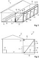
Figur 1 in einer schematischen perspektivischen Ansicht eine erfindungsgemäße Stallanlage mit Halle und Boxen, die entlang der in der Figur rechten Außenseite der Halle aufgereiht sind und sich in der Normalposition befinden; -
Figur 2 die Stallanlage vonFigur 1 in einer Seitenansicht; -
Figur 3 eine Detail-Seitenansicht entsprechendFigur 2 , wobei die Boxen sich in einer Zwischenposition befinden; -
Figur 4 eine Ansicht entsprechendFigur 2 , wobei sich die Boxen in der Reinigungsposition befinden; und -
Figur 5 die Stallanlage in einer perspektivischen Ansicht, wobei sich die Boxen in der Reinigungsposition befinden. - In den
Figuren 1 und 2 ist eine Stallanlage 10 zu sehen. Sie dient insbesondere zur Aufzucht von Kälbern. Grundsätzlich kann diese Stallanlage aber auch zur Aufzucht von anderen Tieren verwendet werden. - Die Stallanlage 10 weist eine Halle 12 auf, die als Tragwerkkonstruktion ausgeführt ist, also ähnlich wie ein Zelt mit einer Rahmenkonstruktion und einer Plane, die das Dach und die Seitenwände abdeckt.
- Der Bereich innerhalb der Halle 12 stellt einen ersten Bereich 14 dar, in dem aufzuziehende Tiere gehalten werden können. Hierzu sind in grundsätzlich bekannter Weise Trenngitter vorhanden, ist hier nicht dargestellt sind. Die Trenngitter dienen dazu, den ersten Bereich nach Wunsch zu unterteilen.
- Im ersten Bereich sind auch mehrere Kleinboxen 16 aufgestellt, in denen sehr junge Tiere (beispielsweise unmittelbar nach der Geburt bis zu einem Alter von wenigen Wochen) gehalten werden können. Bei den Kleinboxen 16 kann es sich insbesondere um Kälberiglus zur Einzelhaltung handeln.
- Die Stallanlage 10 umfasst auch einen zweiten Bereich 20, der sich hier seitlich außerhalb der Halle 12 unmittelbar an diese angrenzend befindet. Der zweite Bereich 20 enthält mehrere Boxen 22, durch die er in getrennte Abteile getrennt ist.
- Jede Box 22 ist hier ein eigenstabiles Bauteil mit Seitenwänden und einem Dach, wobei die Box 22 an einer Seite offen ist, so dass ein Zugang von der Seite der Halle 12 möglich ist. Bei den Boxen 22 kann es sich insbesondere um Großraumiglus zur Gruppenhaltung handeln.
- Hier sind als Beispiel vier Boxen 22 gezeigt. Je nach Größe der Halle können aber auch sehr viel mehr Boxen entlang der Seite der Halle 12 aufgestellt werden.
- Zwischen jeder Box 22 und der Halle 12 ist ein Trenngitter 24 vorgesehen, so dass der Zugang von der Halle 12 zu den Boxen 22 bei Bedarf abgesperrt werden kann.
- Die Boxen 22 sind bewegbar montiert, so dass sie zwischen einer Normalposition und einer Reinigungsposition verstellt werden können. In der Normalposition (siehe die
Figuren 1 und 2 ) steht jede Box 22 auf dem Untergrund auf, so dass jeweils ein Abteil abgetrennt ist, das sich seitlich außerhalb der Halle 12 befindet. - In der Reinigungsposition ist der zweite Bereich 20, in dem sich die Boxen 22 in der Normalposition befinden, völlig freigegeben (siehe die
Figuren 4 und5 ). "Völlig freigegeben" bedeutet, dass der zweite Bereich 20 für beispielsweise einen Traktor zugänglich ist, der entlang der Außenseite der Halle 12 fahren und dabei mit einer Frontladerschaufel den sich dort befindenden Mist zusammenschieben und zur Rückseite der Halle hin schieben kann. Dadurch ist es möglich, in sehr kurzer Zeit den kompletten zweiten Bereich 20 zu säubern, da keinerlei Trennwände etc. mehr im Weg sind. - Die Boxen 22 werden hier aus der Normal- in die Reinigungsposition verstellt, indem sie um ein Gelenk 30 verschwenkt werden. Das Gelenk ist ein Schwenkgelenk, mit dem die Boxen 22 schwenkbar am Untergrund befestigt sind, und zwar an ihrer von der Halle 12 entfernten Rückseite.
- Jede der Boxen 22 ist dabei vorzugsweise an einem Rahmen 32 angebracht, der die entsprechende Box 22 versteift. Das Gelenk 30 ist kann dann gebildet sein durch einen Lagerbolzen, der sich durch Öffnungen im Rahmen 32 und in einer bodenfesten Unterkonstruktion erstreckt, so dass das Schwenklager erhalten ist, um das die Boxen 22 aus der Normal- in die Reinigungsposition verstellt werden können.
- Um die Boxen 22 aus der Normal- in die Reinigungsposition zu verstellen, ist ein Antriebsmechanismus vorgesehen, der einen Antriebsmotor 40 enthält, beispielsweise einen Elektromotor. Der Antriebsmotor wirkt auf eine Seilrolle 42, die Teil eines Seilzugsystems ist, das an den Boxen 22 bzw. deren Rahmen 32 angreift.
- Grundsätzlich sind verschiedene Arten von Seilzugsystemen möglich, mit denen die Boxen an ihrer der Halle 12 zugewandten Vorderseite angehoben und um das Gelenk 30 an der von der Halle 12 abgewandten Rückseite um rund 90° geschwenkt werden können.
- Das Seilzugsystem weist hier ein erstes Seil 44 auf, das als Hebeseil bezeichnet wird, und ein zweites Seil 46, das als Rückstellseil bezeichnet wird.
- Das Hebeseil 44 greift an der Box 22 bzw. dem Rahmen 32 der Box an einer Stelle an, die vom Gelenk 30 aus gesehen näher an der Halle 12 liegt. Beim gezeigten Ausführungsbeispiel greift das Hebeseil an der Vorderseite der Box 22 bzw. des Rahmens 32 an, also im maximalen Abstand vom Gelenk 30.
- Das Rückstellseil 46 greift an der Box 22 bzw. dem Rahmen 32 an einer Stelle an, die, wenn sich die Box in der Reinigungsposition befindet, auf der vom Gelenk 30 abgewandten Seite der Halle 12 befindet. Beim gezeigten Ausführungsbeispiel greift das Rückstellseil 46 an einem Rahmenschenkel 34 an, der sich an der Rückseite der Box 22 in vertikaler Richtung erstreckt, wenn sie sich in der Normalposition befindet.
- Das Hebeseil 44 und das Rückstellseil 46 erstrecken sich ausgehend von der Box 22 bzw. dem Rahmen 32 nach oben hin zu einer Umlenkrolle 48, die etwa vertikal über dem Gelenk 30 an einer Quertraverse 50 angeordnet ist. Von der Umlenkrolle 48 erstrecken sich das Hebe- und das Rückstellseil 44, 46 hin zur Seilrolle 42, die an der Seitenwand der Halle 12 angeordnet ist. Die Seilrolle 42 kann dabei zusammen mit ihrem Antriebsmotor geschützt unter den Dachüberstand der Halle 12 an deren Außenseite montiert sein.
- Querkräfte, die aufgrund der Seilführung auf die Quertraverse 50 wirken, werden von einer Stütztraverse 52 direkt zur Halle 12 abgeleitet.
- Für das Hebe- und das Rückstellseil 44, 46 kann eine einzige Seilrolle 42 verwendet werden, wenn mit geeigneten geometrischen Verhältnissen und/oder Ausgleichsfedern verhindert ist, dass es zu Verspannungen im Seilzugsystem kommt. Alternativ können auch getrennte Seilrollen verwendet werden, die elastisch gegeneinander verdrehbar auf einer gemeinsamen Antriebswelle angeordnet sind, oder völlig separate Seilrollen.
- Wenn die Boxen 22 gereinigt werden sollen, werden zunächst die sich dort befindenden Tiere in die Halle 12 getrieben, und die Trenngitter 24 werden geschlossen, so dass die Tiere nicht mehr in die Boxen 22 zurückkehren können.
- Dann wird, um die Boxen 22 aus der Normal- in die Reinigungsposition zu verstellen, der Antriebsmechanismus so aktiviert, dass das Hebeseil 44 aufgewickelt wird. Dadurch wird die der Halle 12 zugewandte Seite der Boxen 22 angehoben (siehe
Figur 3 ), bis die Boxen 22 sich schließlich in der Reinigungsposition befinden (siehe dieFiguren 4 und5 ), in der die Boxen um rund 90° nach oben geklappt sind. Bei diesem Vorgang wird das Rückstellseil 46 zunächst entsprechend freigegeben. Im zweiten Abschnitt des Rückstellens kommt das Rückstellseil 46 auf Spannung und verhindert, dass die Boxen 22 sich unkontrolliert aufstellen. - Wenn sich die Boxen 22 in der Reinigungsposition befinden, kann der zweite Bereich 20 in einem Durchgang gereinigt werden, beispielweise der sich dort befindende Mist aller Boxen zu einer Seite hin aus der nun freigegebenen "Gasse" ausgeschoben werden.
- Weiterhin ist, wenn sich die Boxen 22 in der Reinigungsposition befinden, die Innenseite jeder Box 22 gut zugänglich. So kann die Innenseite der Boxen 22 mit einem Hochdruckreiniger gesäubert werden. Das dabei anfallende Schmutzwasser sammelt sich auf der (im gekippten Zustand untenliegenden) Rückwand der Box 22 und kann in einer Wasserauffangrinne 60 aufgefangen werden, die sich entlang der Gelenke 30 erstreckt.
- Um die Boxen 22 zurück in die Normalposition zu verstellen, wird der Antriebsmechanismus so aktiviert, dass das Rückstellseil 46 aufgewickelt wird. Dadurch wird das obere Ende der Rückwand der Box 22 angehoben, bis die Boxen 22 sich schließlich wieder in der Normalposition befinden (siehe die
Figuren 1 und 2 ), in der ihre Seitenwände bzw. die Rahmen auf dem Untergrund aufliegen. Bei diesem Vorgang wird das Hebeseil 44 anfänglich entsprechend freigegeben. Im zweiten Abschnitt des Rückstellens kommt das Hebeseil 44 wieder auf Spannung und verhindert, dass die Boxen 22 unkontrolliert nach unten fallen. - Die beschriebenen Stallanlagen 10 kann zur Komplettaufzucht von Kälbern verwendet werden. Die Halle kann optimal belüftet werden und dabei verschiedene Klimazonen aufweisen, so dass dort jederzeit optimale Temperaturverhältnisse herrschen. Falls gewünscht, kann dazu auch eine Klimaanlage vorgesehen werden.
- Ein weiterer Vorteil ist, dass die Stallanlage modular aufgebaut ist. Es kann eine beliebige Anzahl von Boxen entlang der Außenseite der Halle aufgestellt werden, da nicht zwingend die gesamte Außenseite der Halle mit den Boxen erweitert werden muss. Es kann, wenn weitere Boxen aufgestellt werden, auch das Antriebssystem mit geringem Aufwand erweitert werden, indem einfach die Welle, auf der die Seilrollen sitzen, verlängert wird.
Claims (14)
- Stallanlage (10) mit einem ersten Bereich (14) und einem zweiten Bereich (20), in denen sich Tiere aufhalten können, wobei dem zweiten Bereich (20) mindestens eine Box (22) zugeordnet ist, die an mindestens einer Seite offen ist, so dass Tiere in die Box (22) gelangen können, dadurch gekennzeichnet, dass die Box (22) verstellbar montiert ist, so dass sie aus einer Normalposition, in der sie den zweiten Bereich (20) abgrenzt, in eine Reinigungsposition gebracht werden kann, in der ein freier Zugang zum zweiten Bereich (20) möglich ist, und wobei die Box (22) eine eigenstabile Kiste mit Seitenwänden und Dach ist.
- Stallanlage nach Anspruch 1, dadurch gekennzeichnet, dass die Box (22) an einem Rahmen (32) montiert ist.
- Stallanlage nach Anspruch 1 oder 2, dadurch gekennzeichnet, dass die Box (22) in vertikaler Richtung zwischen der Normalposition und der Reinigungsposition verstellbar ist.
- Stallanlage nach Anspruch 1 oder 2, dadurch gekennzeichnet, dass die Box (22) um ein Gelenk (30) zwischen der Normalposition und der Reinigungsposition schwenkbar ist.
- Stallanlage nach einem der vorhergehenden Ansprüche, dadurch gekennzeichnet, dass eine Antriebsvorrichtung (40) vorgesehen ist, mit der die Box (22) aus der Normalposition in die Reinigungsposition verstellt werden kann.
- Stallanlage nach Anspruch 5, dadurch gekennzeichnet, dass die Antriebsvorrichtung (40) ein Seilzugsystem enthält, mit dem die Box (22) angehoben werden kann, um sie aus der Normal- in die Reinigungsposition zu bringen.
- Stallanlage nach Anspruch 6, dadurch gekennzeichnet, dass das Seilzugsystem an zwei voneinander entfernten Punkten an der Box angreift, so dass sie mittels des Seilzugsystems auch aus der Reinigungsposition in die Normalposition zurückgestellt werden kann.
- Stallanlage nach einem der vorhergehenden Ansprüche, dadurch gekennzeichnet, dass eine Wasserauffangrinne (60) vorgesehen ist, mit der auch Schmutzwasser aufgefangen werden kann, das beim Reinigen der Box (22) anfällt.
- Stallanlage nach einem der vorhergehenden Ansprüche, dadurch gekennzeichnet, dass sich der erste Bereich (14) innerhalb einer Halle (12) und der zweite Bereich (20) außerhalb der Halle (12) befindet.
- Stallanlage nach einem der vorhergehenden Ansprüche, dadurch gekennzeichnet, dass innerhalb des ersten Bereichs (14) eine Mehrzahl von Kleinboxen (16) für Jungtiere angeordnet ist.
- Stallanlage nach einem der vorhergehenden Ansprüche, dadurch gekennzeichnet, dass unterschiedliche Klimazonen in der Halle (12) vorgesehen sind.
- Stallanlage nach einem der vorhergehenden Ansprüche, dadurch gekennzeichnet, dass dem ersten und dem zweiten Bereich (14, 20) getrennte Fütterungsautomaten zugeordnet sind, die tierspezifische Futtermengen zur Verfügung stellen.
- Stallanlage nach einem der vorhergehenden Ansprüche, dadurch gekennzeichnet, dass ein Trenngitter (24) vorgesehen ist, mit dem der erste vom zweiten Bereich (14, 20) abgetrennt werden kann.
- Stallanlage nach einem der vorhergehenden Ansprüche, dadurch gekennzeichnet, dass eine Mehrzahl von Boxen (22) vorgesehen ist, die nebeneinander angeordnet sind und gleichzeitig aus der Normal- in die Reinigungsposition verstellt werden können.
Priority Applications (1)
| Application Number | Priority Date | Filing Date | Title |
|---|---|---|---|
| PL15193596T PL3020271T3 (pl) | 2014-11-11 | 2015-11-09 | Instalacja budynku inwentarskiego |
Applications Claiming Priority (1)
| Application Number | Priority Date | Filing Date | Title |
|---|---|---|---|
| DE102014116434.2A DE102014116434A1 (de) | 2014-11-11 | 2014-11-11 | Tieraufzuchtstation |
Publications (2)
| Publication Number | Publication Date |
|---|---|
| EP3020271A1 EP3020271A1 (de) | 2016-05-18 |
| EP3020271B1 true EP3020271B1 (de) | 2017-05-03 |
Family
ID=54539872
Family Applications (1)
| Application Number | Title | Priority Date | Filing Date |
|---|---|---|---|
| EP15193596.2A Active EP3020271B1 (de) | 2014-11-11 | 2015-11-09 | Stallanlage |
Country Status (4)
| Country | Link |
|---|---|
| EP (1) | EP3020271B1 (de) |
| DE (1) | DE102014116434A1 (de) |
| DK (1) | DK3020271T3 (de) |
| PL (1) | PL3020271T3 (de) |
Cited By (1)
| Publication number | Priority date | Publication date | Assignee | Title |
|---|---|---|---|---|
| WO2026027083A1 (de) * | 2024-07-30 | 2026-02-05 | Fürstier Gmbh & Co. Kg | Vorrichtung und verfahren zum ausschleusen von tierkörpern durch eine öffnung in einem wandabschnitt eines gebäudes sowie ein mit einer solchen vorrichtung ausgerüstetes gebäude |
Family Cites Families (3)
| Publication number | Priority date | Publication date | Assignee | Title |
|---|---|---|---|---|
| DE20216251U1 (de) * | 2002-03-12 | 2003-01-09 | Oberndörfer, Erwin, 74575 Schrozberg | Schwenkbare Abtrennvorrichtung für einen Sauenstall sowie Kombinationen dieser Vorrichtungen zu einem Sauenstall für Gruppenhaltung |
| NL1035302C2 (nl) * | 2008-04-16 | 2009-10-19 | Lely Patent Nv | Diervoederinrichting. |
| DE102012012034A1 (de) * | 2012-06-19 | 2013-12-19 | Gerhard Rocker | Schweinestall sowie Verfahren und Mittel zum Umrüsten eines Schweinestalls |
-
2014
- 2014-11-11 DE DE102014116434.2A patent/DE102014116434A1/de not_active Withdrawn
-
2015
- 2015-11-09 PL PL15193596T patent/PL3020271T3/pl unknown
- 2015-11-09 EP EP15193596.2A patent/EP3020271B1/de active Active
- 2015-11-09 DK DK15193596.2T patent/DK3020271T3/en active
Cited By (1)
| Publication number | Priority date | Publication date | Assignee | Title |
|---|---|---|---|---|
| WO2026027083A1 (de) * | 2024-07-30 | 2026-02-05 | Fürstier Gmbh & Co. Kg | Vorrichtung und verfahren zum ausschleusen von tierkörpern durch eine öffnung in einem wandabschnitt eines gebäudes sowie ein mit einer solchen vorrichtung ausgerüstetes gebäude |
Also Published As
| Publication number | Publication date |
|---|---|
| DE102014116434A1 (de) | 2016-05-12 |
| EP3020271A1 (de) | 2016-05-18 |
| PL3020271T3 (pl) | 2017-10-31 |
| DK3020271T3 (en) | 2017-08-28 |
Similar Documents
| Publication | Publication Date | Title |
|---|---|---|
| DE10332418A1 (de) | Stallanordnung und Stallanlage für Milchviehhaltung | |
| EP3402322B1 (de) | Stall, insbesondere für die haltung von schweinen | |
| AT521304A1 (de) | Stall für die Schweinemast | |
| EP1729565A1 (de) | Stallanordnung und stallanlage für milchviehhaltung | |
| DE102010034077B4 (de) | Verfahrbarer Geflügelstall | |
| EP3643163A2 (de) | Trennungsvorrichtung zur emissionsreduktion in ställen und tierstall | |
| EP1477057A1 (de) | Volierensystem für Hühner oder dergleiche | |
| DE102011101089A1 (de) | Schweinestall | |
| EP3020271B1 (de) | Stallanlage | |
| DE102019008051A1 (de) | Vorrichtung für den Aufenthalt von Küken | |
| CH714333B1 (de) | Mobile Kälberbox. | |
| EP3598892B1 (de) | Verfahren zur herstellung einer strohmatte, strohmatte und strohstall | |
| DE3715735C2 (de) | Käfigbatterie für die Geflügelhaltung | |
| DE10023225C1 (de) | Stallgebäude für die Nutztierhaltung | |
| DE102015100279B4 (de) | Vorrichtung zur Bereitstellung von Futter für ein Tier | |
| DE102011087012A1 (de) | Schiebegitter für eine Aufzuchtvoliere | |
| AT524048B1 (de) | Stall | |
| DE2646242C2 (de) | Viehstall, insbes. Melkstand-Stalleinbau | |
| AT18065U2 (de) | Volierenebene mit Nest für einen Hühnerstall zur Haltung von Legehennen | |
| DE202009004716U1 (de) | Stallstandanordnungselement mit Fressgitter und Liegeboxabtrennungselement | |
| EP2022327A1 (de) | Käfig oder dergleichen Beherbungsraum für Geflügelhaltung | |
| EP0027981B1 (de) | Nestanlage für Geflügelfarmen | |
| DE3326124A1 (de) | Mehrzweck-kaefigbatterie | |
| DE102016114725B3 (de) | Futtertisch | |
| DE3820610A1 (de) | Stall zur aufzucht von vieh, insbesondere kaelbern |
Legal Events
| Date | Code | Title | Description |
|---|---|---|---|
| PUAI | Public reference made under article 153(3) epc to a published international application that has entered the european phase |
Free format text: ORIGINAL CODE: 0009012 |
|
| AK | Designated contracting states |
Kind code of ref document: A1 Designated state(s): AL AT BE BG CH CY CZ DE DK EE ES FI FR GB GR HR HU IE IS IT LI LT LU LV MC MK MT NL NO PL PT RO RS SE SI SK SM TR |
|
| AX | Request for extension of the european patent |
Extension state: BA ME |
|
| 17P | Request for examination filed |
Effective date: 20160919 |
|
| RBV | Designated contracting states (corrected) |
Designated state(s): AL AT BE BG CH CY CZ DE DK EE ES FI FR GB GR HR HU IE IS IT LI LT LU LV MC MK MT NL NO PL PT RO RS SE SI SK SM TR |
|
| GRAP | Despatch of communication of intention to grant a patent |
Free format text: ORIGINAL CODE: EPIDOSNIGR1 |
|
| INTG | Intention to grant announced |
Effective date: 20161202 |
|
| GRAS | Grant fee paid |
Free format text: ORIGINAL CODE: EPIDOSNIGR3 |
|
| GRAA | (expected) grant |
Free format text: ORIGINAL CODE: 0009210 |
|
| AK | Designated contracting states |
Kind code of ref document: B1 Designated state(s): AL AT BE BG CH CY CZ DE DK EE ES FI FR GB GR HR HU IE IS IT LI LT LU LV MC MK MT NL NO PL PT RO RS SE SI SK SM TR |
|
| REG | Reference to a national code |
Ref country code: GB Ref legal event code: FG4D Free format text: NOT ENGLISH |
|
| REG | Reference to a national code |
Ref country code: AT Ref legal event code: REF Ref document number: 888919 Country of ref document: AT Kind code of ref document: T Effective date: 20170515 Ref country code: CH Ref legal event code: EP |
|
| REG | Reference to a national code |
Ref country code: IE Ref legal event code: FG4D Free format text: LANGUAGE OF EP DOCUMENT: GERMAN |
|
| REG | Reference to a national code |
Ref country code: DE Ref legal event code: R096 Ref document number: 502015000980 Country of ref document: DE |
|
| REG | Reference to a national code |
Ref country code: NL Ref legal event code: FP |
|
| REG | Reference to a national code |
Ref country code: SE Ref legal event code: TRGR |
|
| REG | Reference to a national code |
Ref country code: DK Ref legal event code: T3 Effective date: 20170822 |
|
| REG | Reference to a national code |
Ref country code: LT Ref legal event code: MG4D |
|
| PG25 | Lapsed in a contracting state [announced via postgrant information from national office to epo] |
Ref country code: FI Free format text: LAPSE BECAUSE OF FAILURE TO SUBMIT A TRANSLATION OF THE DESCRIPTION OR TO PAY THE FEE WITHIN THE PRESCRIBED TIME-LIMIT Effective date: 20170503 Ref country code: HR Free format text: LAPSE BECAUSE OF FAILURE TO SUBMIT A TRANSLATION OF THE DESCRIPTION OR TO PAY THE FEE WITHIN THE PRESCRIBED TIME-LIMIT Effective date: 20170503 Ref country code: LT Free format text: LAPSE BECAUSE OF FAILURE TO SUBMIT A TRANSLATION OF THE DESCRIPTION OR TO PAY THE FEE WITHIN THE PRESCRIBED TIME-LIMIT Effective date: 20170503 Ref country code: ES Free format text: LAPSE BECAUSE OF FAILURE TO SUBMIT A TRANSLATION OF THE DESCRIPTION OR TO PAY THE FEE WITHIN THE PRESCRIBED TIME-LIMIT Effective date: 20170503 Ref country code: GR Free format text: LAPSE BECAUSE OF FAILURE TO SUBMIT A TRANSLATION OF THE DESCRIPTION OR TO PAY THE FEE WITHIN THE PRESCRIBED TIME-LIMIT Effective date: 20170804 Ref country code: NO Free format text: LAPSE BECAUSE OF FAILURE TO SUBMIT A TRANSLATION OF THE DESCRIPTION OR TO PAY THE FEE WITHIN THE PRESCRIBED TIME-LIMIT Effective date: 20170803 |
|
| REG | Reference to a national code |
Ref country code: FR Ref legal event code: PLFP Year of fee payment: 3 |
|
| PG25 | Lapsed in a contracting state [announced via postgrant information from national office to epo] |
Ref country code: IS Free format text: LAPSE BECAUSE OF FAILURE TO SUBMIT A TRANSLATION OF THE DESCRIPTION OR TO PAY THE FEE WITHIN THE PRESCRIBED TIME-LIMIT Effective date: 20170903 Ref country code: RS Free format text: LAPSE BECAUSE OF FAILURE TO SUBMIT A TRANSLATION OF THE DESCRIPTION OR TO PAY THE FEE WITHIN THE PRESCRIBED TIME-LIMIT Effective date: 20170503 Ref country code: BG Free format text: LAPSE BECAUSE OF FAILURE TO SUBMIT A TRANSLATION OF THE DESCRIPTION OR TO PAY THE FEE WITHIN THE PRESCRIBED TIME-LIMIT Effective date: 20170803 Ref country code: LV Free format text: LAPSE BECAUSE OF FAILURE TO SUBMIT A TRANSLATION OF THE DESCRIPTION OR TO PAY THE FEE WITHIN THE PRESCRIBED TIME-LIMIT Effective date: 20170503 |
|
| PG25 | Lapsed in a contracting state [announced via postgrant information from national office to epo] |
Ref country code: RO Free format text: LAPSE BECAUSE OF FAILURE TO SUBMIT A TRANSLATION OF THE DESCRIPTION OR TO PAY THE FEE WITHIN THE PRESCRIBED TIME-LIMIT Effective date: 20170503 Ref country code: SK Free format text: LAPSE BECAUSE OF FAILURE TO SUBMIT A TRANSLATION OF THE DESCRIPTION OR TO PAY THE FEE WITHIN THE PRESCRIBED TIME-LIMIT Effective date: 20170503 Ref country code: EE Free format text: LAPSE BECAUSE OF FAILURE TO SUBMIT A TRANSLATION OF THE DESCRIPTION OR TO PAY THE FEE WITHIN THE PRESCRIBED TIME-LIMIT Effective date: 20170503 |
|
| REG | Reference to a national code |
Ref country code: DE Ref legal event code: R097 Ref document number: 502015000980 Country of ref document: DE |
|
| PG25 | Lapsed in a contracting state [announced via postgrant information from national office to epo] |
Ref country code: SM Free format text: LAPSE BECAUSE OF FAILURE TO SUBMIT A TRANSLATION OF THE DESCRIPTION OR TO PAY THE FEE WITHIN THE PRESCRIBED TIME-LIMIT Effective date: 20170503 |
|
| PLBE | No opposition filed within time limit |
Free format text: ORIGINAL CODE: 0009261 |
|
| STAA | Information on the status of an ep patent application or granted ep patent |
Free format text: STATUS: NO OPPOSITION FILED WITHIN TIME LIMIT |
|
| 26N | No opposition filed |
Effective date: 20180206 |
|
| PG25 | Lapsed in a contracting state [announced via postgrant information from national office to epo] |
Ref country code: SI Free format text: LAPSE BECAUSE OF FAILURE TO SUBMIT A TRANSLATION OF THE DESCRIPTION OR TO PAY THE FEE WITHIN THE PRESCRIBED TIME-LIMIT Effective date: 20170503 |
|
| PG25 | Lapsed in a contracting state [announced via postgrant information from national office to epo] |
Ref country code: MC Free format text: LAPSE BECAUSE OF FAILURE TO SUBMIT A TRANSLATION OF THE DESCRIPTION OR TO PAY THE FEE WITHIN THE PRESCRIBED TIME-LIMIT Effective date: 20170503 |
|
| PG25 | Lapsed in a contracting state [announced via postgrant information from national office to epo] |
Ref country code: LU Free format text: LAPSE BECAUSE OF NON-PAYMENT OF DUE FEES Effective date: 20171109 |
|
| REG | Reference to a national code |
Ref country code: BE Ref legal event code: MM Effective date: 20171130 |
|
| REG | Reference to a national code |
Ref country code: IE Ref legal event code: MM4A |
|
| PG25 | Lapsed in a contracting state [announced via postgrant information from national office to epo] |
Ref country code: MT Free format text: LAPSE BECAUSE OF FAILURE TO SUBMIT A TRANSLATION OF THE DESCRIPTION OR TO PAY THE FEE WITHIN THE PRESCRIBED TIME-LIMIT Effective date: 20170503 |
|
| PG25 | Lapsed in a contracting state [announced via postgrant information from national office to epo] |
Ref country code: IE Free format text: LAPSE BECAUSE OF NON-PAYMENT OF DUE FEES Effective date: 20171109 |
|
| PG25 | Lapsed in a contracting state [announced via postgrant information from national office to epo] |
Ref country code: BE Free format text: LAPSE BECAUSE OF NON-PAYMENT OF DUE FEES Effective date: 20171130 |
|
| PG25 | Lapsed in a contracting state [announced via postgrant information from national office to epo] |
Ref country code: HU Free format text: LAPSE BECAUSE OF FAILURE TO SUBMIT A TRANSLATION OF THE DESCRIPTION OR TO PAY THE FEE WITHIN THE PRESCRIBED TIME-LIMIT; INVALID AB INITIO Effective date: 20151109 |
|
| REG | Reference to a national code |
Ref country code: CH Ref legal event code: PL |
|
| PG25 | Lapsed in a contracting state [announced via postgrant information from national office to epo] |
Ref country code: CH Free format text: LAPSE BECAUSE OF NON-PAYMENT OF DUE FEES Effective date: 20181130 Ref country code: LI Free format text: LAPSE BECAUSE OF NON-PAYMENT OF DUE FEES Effective date: 20181130 |
|
| PG25 | Lapsed in a contracting state [announced via postgrant information from national office to epo] |
Ref country code: CY Free format text: LAPSE BECAUSE OF FAILURE TO SUBMIT A TRANSLATION OF THE DESCRIPTION OR TO PAY THE FEE WITHIN THE PRESCRIBED TIME-LIMIT Effective date: 20170503 |
|
| PG25 | Lapsed in a contracting state [announced via postgrant information from national office to epo] |
Ref country code: MK Free format text: LAPSE BECAUSE OF FAILURE TO SUBMIT A TRANSLATION OF THE DESCRIPTION OR TO PAY THE FEE WITHIN THE PRESCRIBED TIME-LIMIT Effective date: 20170503 |
|
| PG25 | Lapsed in a contracting state [announced via postgrant information from national office to epo] |
Ref country code: PT Free format text: LAPSE BECAUSE OF FAILURE TO SUBMIT A TRANSLATION OF THE DESCRIPTION OR TO PAY THE FEE WITHIN THE PRESCRIBED TIME-LIMIT Effective date: 20170503 |
|
| PG25 | Lapsed in a contracting state [announced via postgrant information from national office to epo] |
Ref country code: AL Free format text: LAPSE BECAUSE OF FAILURE TO SUBMIT A TRANSLATION OF THE DESCRIPTION OR TO PAY THE FEE WITHIN THE PRESCRIBED TIME-LIMIT Effective date: 20170503 |
|
| GBPC | Gb: european patent ceased through non-payment of renewal fee |
Effective date: 20191109 |
|
| PG25 | Lapsed in a contracting state [announced via postgrant information from national office to epo] |
Ref country code: GB Free format text: LAPSE BECAUSE OF NON-PAYMENT OF DUE FEES Effective date: 20191109 |
|
| PGFP | Annual fee paid to national office [announced via postgrant information from national office to epo] |
Ref country code: SE Payment date: 20211118 Year of fee payment: 7 Ref country code: TR Payment date: 20211108 Year of fee payment: 7 Ref country code: CZ Payment date: 20211108 Year of fee payment: 7 Ref country code: DK Payment date: 20211122 Year of fee payment: 7 |
|
| PGFP | Annual fee paid to national office [announced via postgrant information from national office to epo] |
Ref country code: NL Payment date: 20221118 Year of fee payment: 8 Ref country code: IT Payment date: 20221124 Year of fee payment: 8 Ref country code: FR Payment date: 20221129 Year of fee payment: 8 Ref country code: DE Payment date: 20221128 Year of fee payment: 8 |
|
| PGFP | Annual fee paid to national office [announced via postgrant information from national office to epo] |
Ref country code: PL Payment date: 20221107 Year of fee payment: 8 |
|
| REG | Reference to a national code |
Ref country code: DK Ref legal event code: EBP Effective date: 20221130 |
|
| REG | Reference to a national code |
Ref country code: SE Ref legal event code: EUG |
|
| PG25 | Lapsed in a contracting state [announced via postgrant information from national office to epo] |
Ref country code: CZ Free format text: LAPSE BECAUSE OF NON-PAYMENT OF DUE FEES Effective date: 20221109 |
|
| PG25 | Lapsed in a contracting state [announced via postgrant information from national office to epo] |
Ref country code: SE Free format text: LAPSE BECAUSE OF NON-PAYMENT OF DUE FEES Effective date: 20221110 |
|
| REG | Reference to a national code |
Ref country code: DE Ref legal event code: R082 Ref document number: 502015000980 Country of ref document: DE |
|
| PG25 | Lapsed in a contracting state [announced via postgrant information from national office to epo] |
Ref country code: DK Free format text: LAPSE BECAUSE OF NON-PAYMENT OF DUE FEES Effective date: 20221130 |
|
| REG | Reference to a national code |
Ref country code: DE Ref legal event code: R119 Ref document number: 502015000980 Country of ref document: DE |
|
| REG | Reference to a national code |
Ref country code: NL Ref legal event code: MM Effective date: 20231201 |
|
| PG25 | Lapsed in a contracting state [announced via postgrant information from national office to epo] |
Ref country code: NL Free format text: LAPSE BECAUSE OF NON-PAYMENT OF DUE FEES Effective date: 20231201 |
|
| PG25 | Lapsed in a contracting state [announced via postgrant information from national office to epo] |
Ref country code: TR Free format text: LAPSE BECAUSE OF NON-PAYMENT OF DUE FEES Effective date: 20221109 Ref country code: NL Free format text: LAPSE BECAUSE OF NON-PAYMENT OF DUE FEES Effective date: 20231201 |
|
| PG25 | Lapsed in a contracting state [announced via postgrant information from national office to epo] |
Ref country code: DE Free format text: LAPSE BECAUSE OF NON-PAYMENT OF DUE FEES Effective date: 20240601 |
|
| PG25 | Lapsed in a contracting state [announced via postgrant information from national office to epo] |
Ref country code: FR Free format text: LAPSE BECAUSE OF NON-PAYMENT OF DUE FEES Effective date: 20231130 |
|
| PG25 | Lapsed in a contracting state [announced via postgrant information from national office to epo] |
Ref country code: FR Free format text: LAPSE BECAUSE OF NON-PAYMENT OF DUE FEES Effective date: 20231130 Ref country code: DE Free format text: LAPSE BECAUSE OF NON-PAYMENT OF DUE FEES Effective date: 20240601 |
|
| PG25 | Lapsed in a contracting state [announced via postgrant information from national office to epo] |
Ref country code: IT Free format text: LAPSE BECAUSE OF NON-PAYMENT OF DUE FEES Effective date: 20231109 |
|
| PG25 | Lapsed in a contracting state [announced via postgrant information from national office to epo] |
Ref country code: IT Free format text: LAPSE BECAUSE OF NON-PAYMENT OF DUE FEES Effective date: 20231109 |
|
| PG25 | Lapsed in a contracting state [announced via postgrant information from national office to epo] |
Ref country code: PL Free format text: LAPSE BECAUSE OF NON-PAYMENT OF DUE FEES Effective date: 20231109 |
|
| PGFP | Annual fee paid to national office [announced via postgrant information from national office to epo] |
Ref country code: AT Payment date: 20260203 Year of fee payment: 11 |