EP3020357B1 - Zahnersatz-erzeugungsvorrichtung - Google Patents
Zahnersatz-erzeugungsvorrichtung Download PDFInfo
- Publication number
- EP3020357B1 EP3020357B1 EP14193333.3A EP14193333A EP3020357B1 EP 3020357 B1 EP3020357 B1 EP 3020357B1 EP 14193333 A EP14193333 A EP 14193333A EP 3020357 B1 EP3020357 B1 EP 3020357B1
- Authority
- EP
- European Patent Office
- Prior art keywords
- auxiliary element
- abutment
- forming device
- tooth replacement
- tube portion
- Prior art date
- Legal status (The legal status is an assumption and is not a legal conclusion. Google has not performed a legal analysis and makes no representation as to the accuracy of the status listed.)
- Active
Links
Images


Classifications
-
- A—HUMAN NECESSITIES
- A61—MEDICAL OR VETERINARY SCIENCE; HYGIENE
- A61C—DENTISTRY; APPARATUS OR METHODS FOR ORAL OR DENTAL HYGIENE
- A61C13/00—Dental prostheses; Making same
- A61C13/0003—Making bridge-work, inlays, implants or the like
- A61C13/0006—Production methods
-
- A—HUMAN NECESSITIES
- A61—MEDICAL OR VETERINARY SCIENCE; HYGIENE
- A61C—DENTISTRY; APPARATUS OR METHODS FOR ORAL OR DENTAL HYGIENE
- A61C8/00—Means to be fixed to the jaw-bone for consolidating natural teeth or for fixing dental prostheses thereon; Dental implants; Implanting tools
- A61C8/0048—Connecting the upper structure to the implant, e.g. bridging bars
- A61C8/005—Connecting devices for joining an upper structure with an implant member, e.g. spacers
-
- A—HUMAN NECESSITIES
- A61—MEDICAL OR VETERINARY SCIENCE; HYGIENE
- A61C—DENTISTRY; APPARATUS OR METHODS FOR ORAL OR DENTAL HYGIENE
- A61C13/00—Dental prostheses; Making same
- A61C13/0003—Making bridge-work, inlays, implants or the like
- A61C13/0004—Computer-assisted sizing or machining of dental prostheses
-
- A—HUMAN NECESSITIES
- A61—MEDICAL OR VETERINARY SCIENCE; HYGIENE
- A61C—DENTISTRY; APPARATUS OR METHODS FOR ORAL OR DENTAL HYGIENE
- A61C13/00—Dental prostheses; Making same
- A61C13/20—Methods or devices for soldering, casting, moulding or melting
-
- A—HUMAN NECESSITIES
- A61—MEDICAL OR VETERINARY SCIENCE; HYGIENE
- A61C—DENTISTRY; APPARATUS OR METHODS FOR ORAL OR DENTAL HYGIENE
- A61C13/00—Dental prostheses; Making same
- A61C13/34—Making or working of models, e.g. preliminary castings, trial dentures; Dowel pins [4]
-
- A—HUMAN NECESSITIES
- A61—MEDICAL OR VETERINARY SCIENCE; HYGIENE
- A61C—DENTISTRY; APPARATUS OR METHODS FOR ORAL OR DENTAL HYGIENE
- A61C8/00—Means to be fixed to the jaw-bone for consolidating natural teeth or for fixing dental prostheses thereon; Dental implants; Implanting tools
- A61C8/0048—Connecting the upper structure to the implant, e.g. bridging bars
- A61C8/005—Connecting devices for joining an upper structure with an implant member, e.g. spacers
- A61C8/0054—Connecting devices for joining an upper structure with an implant member, e.g. spacers having a cylindrical implant connecting part
-
- A—HUMAN NECESSITIES
- A61—MEDICAL OR VETERINARY SCIENCE; HYGIENE
- A61C—DENTISTRY; APPARATUS OR METHODS FOR ORAL OR DENTAL HYGIENE
- A61C8/00—Means to be fixed to the jaw-bone for consolidating natural teeth or for fixing dental prostheses thereon; Dental implants; Implanting tools
- A61C8/0048—Connecting the upper structure to the implant, e.g. bridging bars
- A61C8/005—Connecting devices for joining an upper structure with an implant member, e.g. spacers
- A61C8/0066—Connecting devices for joining an upper structure with an implant member, e.g. spacers with positioning means
-
- A—HUMAN NECESSITIES
- A61—MEDICAL OR VETERINARY SCIENCE; HYGIENE
- A61C—DENTISTRY; APPARATUS OR METHODS FOR ORAL OR DENTAL HYGIENE
- A61C8/00—Means to be fixed to the jaw-bone for consolidating natural teeth or for fixing dental prostheses thereon; Dental implants; Implanting tools
- A61C2008/0084—Provisional implants or abutments
-
- A—HUMAN NECESSITIES
- A61—MEDICAL OR VETERINARY SCIENCE; HYGIENE
- A61C—DENTISTRY; APPARATUS OR METHODS FOR ORAL OR DENTAL HYGIENE
- A61C8/00—Means to be fixed to the jaw-bone for consolidating natural teeth or for fixing dental prostheses thereon; Dental implants; Implanting tools
- A61C8/0012—Means to be fixed to the jaw-bone for consolidating natural teeth or for fixing dental prostheses thereon; Dental implants; Implanting tools characterised by the material or composition, e.g. ceramics, surface layer, metal alloy
- A61C8/0016—Means to be fixed to the jaw-bone for consolidating natural teeth or for fixing dental prostheses thereon; Dental implants; Implanting tools characterised by the material or composition, e.g. ceramics, surface layer, metal alloy polymeric material
Definitions
- the invention relates to a tooth replacement production device according to the preamble of claim 1.
- Dentures are often fastened in a patient's mouth with the aid of an implant.
- the implant is typically provided with what is known as an abutment after it has been introduced, which is connected to the implant in a true-to-shape manner, for example by virtue of the fact that the mutually facing surfaces of the implant and abutment are non-round.
- the attachment itself is then carried out using an abutment screw that penetrates the abutment.
- an upper area of the abutment is designed as a pipe section, the inner diameter of which is sufficient to accommodate the abutment screw.
- the abutment screw rests somewhat below this pipe section on a mostly somewhat conical support area, the inner diameter of which is smaller than the head diameter of the abutment screw, through which, however, the shaft and the thread of the abutment screw fit.
- the implant then has, in a manner known per se, an internal thread for thread engagement with the thread of the abutment screw.
- a dental structure is then fastened on the abutment to the fastening of the abutment to the implant.
- the tube section or upper area of the abutment is usually slightly conical on the outside and fits true to shape into a corresponding recess in the dental structure.
- the invention is based on the object of creating a tooth replacement generating device according to the preamble of claim 1, which can be used better and universally, the restoration result also being improved, in particular with regard to the adhesion to the abutment.
- the abutment is present on its tube section with an outer radius that is not exceeded at any point.
- No anti-rotation spring protrudes into the auxiliary element, so that it is not weakened at this point.
- the pipe section is provided with a longitudinally parallel groove to provide the outside as a rotation protection element and the auxiliary element accordingly with an in particular optionally provided rotation protection spring that fits the groove.
- any desired rotational position can be adopted for the provision of a bridge as a dental restoration, and the desired automatic angle setting, as is the case with bridges, is guaranteed. It is also possible to manually remove the pre-made anti-rotation spring to achieve this effect.
- the wall thickness of the auxiliary element is uniform and, in particular, is not undershot at any point, so that it is not weakened.
- a wall thickness of 150 ⁇ m to 250 ⁇ m can be specified, and the auxiliary element - optionally with an industrially prefabricated, for example blasted surface - can be in close contact with the pipe section, with a clearance-free fit.
- the wall thickness of the auxiliary element can also be predominantly between 100 ⁇ m and 350 ⁇ m, preferably around 200 ⁇ m, at least apart from the areas in which a rotation lock is provided.
- the auxiliary element is prefabricated and accordingly has a preconditioned surface with a predetermined roughness, in particular both radially on the inside, that is to say towards the abutment, and radially on the outside.
- the auxiliary element preferably has a greater roughness on its radial outer surface than on its radial inner surface.
- the greater the roughness the lower the accuracy of fit. This applies both inside, i.e. towards the abutment, and outside, i.e. towards the superstructure. This roughness setting has the advantage for dental technicians that the auxiliary element no longer has to be re-assembled.
- the size dimensions of the auxiliary element and the abutment are selected so that the auxiliary element can be pushed onto the abutment, in particular also onto its pipe section, with a play-free fit.
- the adhesive joint between the superstructure or dental structure of the restoration and the abutment can be ensured in the desired quality with a correspondingly uniform wall thickness.
- a hard wax or even polyacrylic can be used as the material, and the industrially preconditioned outer surface of the auxiliary element also enables wax modeling and a secure connection of the wax modeling that may be desired if required.
- the adhesive gap or the adhesive joint preferably has a constant thickness. In the area of the collar of the abutment, however, it is preferred that the adhesive gap is reduced; this increases the accuracy of fit.
- the abutment has an adhesive receiving groove at a transition between its tube section and a circumferential collar, which in particular is formed circumferentially adjacent to the collar and that the auxiliary element has at least one projection, in particular a circumferential projection, which is intended for engagement in this groove.
- the gluing and modeling aid has a gripping handle which, when the gluing and modeling aid is inserted into the pipe section, extends above the pipe section.
- the bonding and modeling aid has a predetermined breaking point which extends in particular just above the pipe section of the abutment when the bonding and modeling aid is in the inserted state.
- the auxiliary element can preferably be shortened at predetermined heights.
- a starting height is provided, and markings for shortening to two further heights are advantageously provided, with the shortening particularly preferably taking place with a tool suitable for this purpose.
- the auxiliary element can be adapted to height-varying or classifiable abutments.
- the auxiliary element preferably has essentially the same wall thickness over its entire height. In the area of the tube section of the abutment, it thus extends downwards, precisely adapted to the length of this tube section, as far as the collar of the abutment.
- An inner shoulder of the auxiliary element is formed at the point at which the tube section of the abutment ends at an end face, and the inner and outer diameter of the auxiliary element jumps back from this point while maintaining the wall thickness.
- the length of the auxiliary element above the pipe section corresponds essentially to the length of the auxiliary element which rests on the abutment.
- this upper section of the auxiliary element preferably extends inside flush with the tube section of the abutment.
- the auxiliary element engages in this and to that extent has a correspondingly downward / inward-facing projection for engaging in this groove.
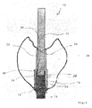
- the illustrated tooth replacement production device 10 has a dental structure 12 as a superstructure. This is mounted on an abutment 14 which is screwed onto an implant (not shown) in a manner known per se. Even if a single crown is shown here, it goes without saying that a dental bridge can also be implemented in an equivalent manner.
- the abutment has a collar 16 and a tube section 18.
- the pipe section 18 extends in a manner known per se with a constant wall thickness. At least one point it has a groove 20 to provide a rotation lock. This is in Fig. 1 to be seen there on the smaller wall thickness of the pipe section 18.
- an auxiliary element 22 is provided which extends with a constant wall thickness over the entire pipe section 18 and beyond.
- the auxiliary element 22 consists of a material that can be removed without residue, such as a polymer, and has an industrially preconditioned surface.
- the auxiliary element 22 is used to produce the dental restoration part, that is to say, for example, the preheating of a muffle in a preheating furnace when the dental restoration part is produced in a common pressing process, is removed without leaving any residue.
- Its wall thickness determines the thickness of an adhesive gap for bonding a superstructure to the abutment.
- the wall thickness of the auxiliary element 22 - and thus the adhesive gap - is between 0.01 mm and 0.5 mm, preferably less than 0.05 mm, and can be designed to be uniform over the course, but if necessary also change over the course.
- the auxiliary element 22 consists of a tubular holder section 24 and a tube section 26 with a smaller diameter in comparison, but the same wall thickness. At the transition between the holder section 24 and the tube section 26, an inner shoulder 28 is provided, the design of which matches an end face 30 of the tube section of the abutment 14.
- the auxiliary element 22 is self-retaining on the pipe section, so that it adheres in a force-fitting and / or form-fitting manner, the holding force preferably being less than 10 kN and more than 50N.
- the tube section 18 of the abutment 14 also has a number of depressions, in particular grooves 20, as an anti-twist device, which in particular engage with these projections of the auxiliary element 22 that are true to shape and are also referred to as springs.
- the number of projections of the auxiliary element 22 is less than or equal to the number of recesses 20 of the pipe section 18
- an adhesive and modeling aid 32 is provided, which is inserted into the pipe section 26 and partly also into the pipe section 18. It ends in a slight cone 34 and closes there tightly against the pipe section 18.
- the adhesive and modeling aid ensures that the interior of the abutment 14 is sealed tightly so that no material can inadvertently penetrate there that would impair access to the implant screw.
- the bonding and modeling aid 32 is securely inserted into the abutment due to its cone 34, but can be removed if necessary after it extends clearly upwards over the pipe section 26.
- the bonding and modeling aid 32 is preferably produced separately from the auxiliary element 22. However, a one-piece implementation is also possible.
- the auxiliary element 22 has, on its holder section 24, a radially inwardly projecting tongue 40 which is convex and fits to the groove 20 on the tube section 18 of the abutment 14.
- the holder portion 24 terminates in a flange 42 which projects radially outward and has an inner shape that matches a corresponding radius between the collar 16 and the tube portion 18 of the abutment 14.
- the extends Flange 42 by a small amount, such as 10 ⁇ m, beyond collar 16 to improve attachment.
- the material thickness or wall thickness of the auxiliary element 22 is preferably increased significantly, in particular approximately doubled, on the auxiliary element 22 at the point or locations at which a rotation lock is provided.
- the auxiliary element 22 has an inner radius 46 which matches the corresponding configuration on the end face 30 of the abutment. The auxiliary element thus rests on the abutment 14 over its entire surface and with an optimally uniformly low wall thickness.
- the gluing and modeling aid 32 here has a gripping handle 50 which, in the exemplary embodiment shown, is essentially sheet-shaped.
- a predetermined breaking point 52 is provided just below the gripping handle 50, at which the adhesive and modeling aid can be broken off if necessary.
- Your plug-in section 54 then completely fills the pipe section 18. Since the adhesive and modeling aid 32 also consists of a material that can be removed without leaving any residue, it can also be removed when the auxiliary element 22 is removed without leaving any residue.
- the adhesive and modeling aid 32 securely blocks the pipe section 18 against the ingress of foreign materials, so that access to the implant screw is always guaranteed.
- the auxiliary element preferably has a reference surface and / or a scannable marking, which and its position in space can be detected by a scanning device, which is in particular part of the CAD / CAM device.
- a scanning device which is in particular part of the CAD / CAM device.
- an auxiliary element identified by the scanning device - the wall thickness of which is known - can be used in the design of the adhesive gap by CAM.
- the CAD / CAM device based on the adhesive gap established by it, specifies an auxiliary element that can be identified via the marking, where the scanning of the marking allows checking whether the relevant auxiliary element is being used.
- the reference surfaces and / or markings are not only useful for designing the adhesive gap, but also serve in particular as a reference surface for the position of the abutment and / or rotation protection in connection with the patient situation.
- the larger this reference area the better and more accurate the scan comparison.
- the auxiliary element and / or the adhesive aid can be provided in one piece and / or in two pieces.
Landscapes
- Health & Medical Sciences (AREA)
- Animal Behavior & Ethology (AREA)
- Dentistry (AREA)
- Epidemiology (AREA)
- Life Sciences & Earth Sciences (AREA)
- Oral & Maxillofacial Surgery (AREA)
- General Health & Medical Sciences (AREA)
- Public Health (AREA)
- Veterinary Medicine (AREA)
- Orthopedic Medicine & Surgery (AREA)
- Engineering & Computer Science (AREA)
- Manufacturing & Machinery (AREA)
- Dental Prosthetics (AREA)
Description
- Die Erfindung betrifft eine Zahnersatz-Erzeugungsvorrichtung, gemäß dem Oberbegriff von Anspruch 1.
- Aus der
US 2009/317769 A1 , derUS 2012/214130 A1 , derUS 2012/183925 A1 und derJP 2010 119465 A - Zahnersatz wird häufig unter Zuhilfenahme eines Implantats im Mund eines Patienten befestigt. In diese Fällen wird typischerweise das Implantat nach Einbringung mit einem sogenannten Abutment versehen, welches formtreu mit dem Implantat in Verbindung steht, beispielsweise dadurch, dass die einander zugewandten Oberflächen von Implantat und Abutment unrund gestaltet sind. Die Befestigung selbst erfolgt dann über eine Abutmentschraube, die das Abutment durchdringt. Hierzu ist ein oberer Bereich des Abutments als Rohrabschnitt ausgebildet, dessen Innendurchmesser für die Aufnahme der Abutmentschraube ausreicht. Die Abutmentschraube liegt etwas unterhalb dieses Rohrabschnitts an einem meist etwas konischen Stützbereich auf, dessen Innendurchmesser kleiner als der Kopfdurchmesser der Abutmentschraube ist, durch welche hindurch aber der Schaft und das Gewinde der Abutmentschraube passt. Das Implantat weist dann in an sich bekannter Weise ein Innengewinde für den Gewindeeingriff mit dem Gewinde der Abutmentschraube auf.
- Auf dem Abutment wird anschließend an die Befestigung des Abutments an dem Implantat eine Dentalstruktur befestigt. Hierzu ist der Rohrabschnitt oder obere Bereich des Abutments außen meist leicht konisch und passt formtreu in eine entsprechende Ausnehmung in der Dentalstruktur.
- Derartige Lösungen werden seit etwa 30 Jahren eingesetzt; beispielhaft insofern sei auf die
DE 32 41 963 C1 oder dieGB 2 119 258 A - Gerade bei der Lösung gemäß letzterer Druckschrift besteht jedoch das Problem, dass die Drehposition der Dentalstruktur relativ zu dem Implantat nicht bzw. nicht eindeutig festgelegt ist. Eine insofern bessere und etwas neuere Lösung lässt sich aus der
US 5,782,918 A1 entnehmen, die eine Rotationssicherung in Form einer Abflachung dem Rohrabschnitt des Abutments zeigt und insofern eine Rotationssicherung zwischen Implantat und Dentalstruktur realisiert. - Bei dieser Lösung ist lediglich eine einzige Größe bzw. Höhe des Abutments vorgesehen, die so klein gehalten ist, dass auch kompaktere Dentalstrukturen den Rohrabschnitt vollständig überdecken.
- Um die Handhabung und insbesondere auch den Prozessablauf bei der sicheren Befestigung der Suprakonstruktion auf dem Abutment zu erleichtern, sind bereits verschiedene Hilfselemente vorgeschlagen worden.
- So ist es vorgeschlagen worden, kurzerhand eine Art Schlauch mit einer Wandstärke von beispielsweise 0,5 mm auf den Rohrabschnitt des Abutments aufzuschieben, um zu gewährleisten, dass später ein ausreichender Klebespalt bereitgestellt ist. Aufgrund der Elastizität des Schlauchs ist aber keine gleichmäßige - und zudem geringe - Dicke des Klebespalts realisierbar.
- Ferner sind auch vorgefertigte Hilfselemente vorgeschlagen worden, bei denen eine Rotationssicherung durch einen nach auswärts weisenden Vorsprung gewährleistet ist. Diese Art des Rotationsschutz ergibt jedoch Probleme bei der Realisierung von Brücken, die grundsätzlich von der Winkelstellung her selbstjustierend sind, so dass ein derartiger Rotationsschutz stört.
- Ein weiteres Problem sind die insofern bereitgestellten Unterschnitte und Retentionsrillen, die vergleichsweise große Klebefugen generieren. Die Haftfähigkeit ist hierdurch in diesen Bereichen vergleichsweise stark reduziert, zumal dies andererseits in anderen Bereichen gegebenenfalls zur Unterschreidung von Materialwandstärken, insbesondere im marginalen Bereich der Restauration, führen kann.
- Demgegenüber liegt der Erfindung die Aufgabe zugrunde, eine Zahnersatz-Erzeugungsvorrichtung gemäß dem Oberbegriff von Anspruch 1 zu schaffen, die besser und universell verwendbar ist, wobei auch das Restaurationsergebnis insbesondere hinsichtlich der Haftung auf dem Abutment verbessert ist.
- Diese Aufgabe wird erfindungsgemäß durch Anspruch 1 gelöst. Vorteilhafte Weiterbildungen ergeben sich aus den Unteransprüchen.
- Erfindungsgemäß besonders günstig ist es, dass das Abutment an seinem Rohrabschnitt mit einem Außenradius vorliegt, der an keiner Stelle überschritten wird. Damit ragt keine Rotationsschutz-Feder in das Hilfselement hinein, so dass es auch keine Schwächung an dieser Stelle erfährt. Vielmehr ist es vorgesehen, den Rohrabschnitt mit einer längsachsparallelen Rille an der Außenseite als Rotationsschutzelement zu versehen und das Hilfselement dementsprechend mit einer insbesondere fakultativ vorgesehenen Rotationsschutz-Feder, die zu der Rille passt.
- Wenn diese weggelassen wird, lässt sich für die Bereitstellung einer Brücke als Dentalrestauration eine beliebige Rotationsstellung einnehmen, und die erwünschte automatische Winkeleinstellung, wie sie sich bei Brücken ergibt, ist gewährleistet. Es ist auch möglich, die vorgefertigte Rotationsschutzfeder manuell zu entfernen, um diese Wirkung zu erzielen.
- Erfindungsgemäß ist es damit zudem günstig, dass die Wandstärke des Hilfselements gleichmäßig und insbesondere an keiner Stelle unterschritten ist, so dass es nicht geschwächt ist. Es lässt sich beispielsweise eine Wandstärke von 150 µm bis 250 µm vorgeben, und das Hilfselement kann - optional mit industriell vorgefertigter, beispielsweise gestrahlter Oberfläche - eng an dem Rohrabschnitt anliegen, in spielfreier Passung. Die Wandstärke des Hilfselements kann auch überwiegend zwischen 100 µm und 350 µm, bevorzugt um 200 µm, betragen, jedenfalls abgesehen von den Bereichen, in denen eine Rotationssicherung vorgesehen ist.
- Das Hilfselement ist vorgefertigt und weist dementsprechend eine vorkonditionierte Oberfläche mit einer vorgegebenen Rauhigkeit auf, insbesondere sowohl radial innen, also zum Abutment hin, als auch radial außen.
- Bevorzugt weist das Hilfselement an seiner radialen Außenfläche eine größere Rauigkeit als an seiner radialen Innenfläche auf. Je grösser die Rauhigkeit ist, desto geringer ist die Passgenauigkeit. Dies gilt sowohl innen, also zum Abutment hin, als auch außen, also zur Suprastruktur hin. Durch diese Rauhigkeitseinstellung besteht der Vorteil für Zahntechniker, dass das Hilfselement nicht mehr nachkonfektioniert werden muss.
- Die Größenabmessungen des Hilfselements und des Abutments sind so gewählt, dass das Hilfselement in spielfreier Passung auf das Abutment, insbesondere auch auf dessen Rohrabschnitt, aufschiebbar ist.
- Nachdem es aus einem rückstandsfrei entfernbaren, insbesondere verbrennbarem, Material ausgebildet ist, lässt sich die Klebefuge zwischen der Suprastruktur oder Dentalstruktur der Restauration und dem Abutment in der erwünschten Qualität mit entsprechend gleichmäßiger Wandstärke gewährleisten. Als Material kommt beispielsweise eine hart eingestelltes Wachs oder auch Polyacryl in Frage, und die industriell vorkonditionierte Außenfläche des Hilfselements ermöglicht auch bei Bedarf eine Wachsmodellation und einen sicheren Anschluss der gegebenenfalls erwünschten Wachsmodellation.
- Bevorzugt weist der Klebespalt oder die Klebefuge eine gleichbleibende Stärke auf. Im Bereich des Kragens des Abutments ist es allerdings bevorzugt, dass der Klebespalt reduziert ist; dies erhöht die Passgenauigkeit.
- Bei Realisierung einer Klebstoffaufnahmerille wird günstigerweise überflüssiger Klebstoff verdrängt und dort aufgenommen. Wenn keine derartige Klebstoffaufnahmerille vorgesehen ist, wird überflüssiger Klebstoff nach oben vom Kragen abgewandten Rohrabschnitt hin verdrängt.
- Die Realisierung einer Klebstoffaufnahmerille ist insofern nicht unbedingt erforderlich und aus Gründen der leichteren Handhabbarkeit ist es günstig, wenn eine solche nicht vorgesehen ist.
- In einer modifizierten Ausgestaltung ist es vorgesehen, dass das Abutment an einem Übergang zwischen seinem Rohrabschnitt und einem umlaufenden Kragen eine Klebstoff-Aufnahmerille aufweist, die insbesondere dem Kragen benachbart umlaufend ausgebildet ist und dass das Hilfselement mindestens einen Vorsprung, insbesondere einen umlaufenden Vorsprung, aufweist, der für den Eingriff in diese Rille bestimmt ist.
- In einer modifizierten Ausgestaltung ist es vorgesehen, dass die Klebe- und Modellierhilfe eine Greifhandhabe aufweist, sich bei in den Rohrabschnitt eingeführtem Zustand der Klebe- und Modellierhilfe oberhalb des Rohrabschnitts erstreckt.
- In einer modifizierten Ausgestaltung ist es vorgesehen, dass die Klebe- und Modellierhilfe eine Sollbruchstelle aufweist, die sich insbesondere knapp oberhalb des Rohrabschnitts des Abutments in eingeführtem Zustand der Klebe- und Modellierhilfe erstreckt.
- Bevorzugt ist das Hilfselement in vorgegebenen Höhen kürzbar. Hierzu wird eine Ausgangshöhe bereitgestellt, und günstigerweise sind Markierungen zum Kürzen auf zwei weitere Höhen vorgesehen, wobei das Kürzen besonders bevorzugt mit einem hierfür geeignetem Werkzeug erfolgt. Insofern ist das Hilfselement zu höhenvariierenden oder klassifizierbaren Abutments anpassbar.
- Bevorzugt weist das Hilfselement über seine gesamte Höhe im wesentlichen die gleiche Wandstärke auf. Im Bereich des Rohrabschnitts des Abutments erstreckt es sich damit exakt angepasst an die Länge dieses Rohrabschnitts bis zum Kragen des Abutments nach unten. An der Stelle, an der der Rohrabschnitts des Abutments an einer Stirnfläche ausläuft, ist eine Innenschulter des Hilfselements ausgebildet, und der Innen- und Außendurchmesser des Hilfelements springt ab dieser Stelle unter Beibehaltung der Wandstärke zurück. Die Länge des Hilfselements oberhalb des Rohrabschnitts entspricht im wesentlichen der Länge des Hilfselements, die am Abutment anliegt.
- Bevorzugt erstreckt sich die Innenseite dieses oberen Abschnitts des Hilfselements innen bündig mit dem Rohrabschnitt des Abutments. Der rohrförmige Abschnitt des Hilfselements oberhalb hat dementsprechend einen geringeren Außendurchmesser als der rohrförmige Halterabschnitt des Hilfselements, an welchem auch der Rohrabschnitt des Abutment aufgesteckt ist.
- Wenn das Abutment an dem Übergang zwischen Rohrabschnitt und Kragen eine Klebstoffaufnahmerille aufweist, ist es bevorzugt, dass das Hilfselement in diese eingreift und insofern einen entsprechend nach unten/innen einwärts gewandten Vorsprung für den Eingriff in diese Rille aufweist.
- Weitere Vorteile, Einzelheiten und Merkmale ergeben sich aus der nachstehenden Beschreibung zweier Ausführungsbeispiele der Erfindung anhand der Zeichnungen.
- Es zeigen:
- Fig. 1
- eine schematische Darstellung einer Zahnersatz-Erzeugungsvorrichtung, unter Darstellung der Dentalstruktur aus Dentalwerkstoff, des Hilfselements und des Abutments sowie auch einer Klebe- und Modellierhilfe;
- Fig. 2
- das Hilfselement gemäß
Fig. 1 in einer anderen Darstellung; und - Fig. 3
- eine weitere Ausgestaltung einer erfindungsgemäßen Zahnersatz-Erzeugungsvorrichtung.
- Die in
Fig. 1 dargestellte Zahnersatz-Erzeugungsvorrichtung 10 weist eine Dentalstruktur 12 als Suprastruktur auf. Diese ist auf einem Abutment 14 gelagert, das in an sich bekannter Weise auf ein nicht dargestelltes Implantat aufgeschraubt ist. Auch wenn hier eine Einzelkrone dargestellt ist, versteht sich, dass in äquivalenter Weise auch eine dentale Brücke realisierbar ist. - Das Abutment weist einen Kragen 16 und eine Rohrabschnitt 18 auf. Der Rohrabschnitt 18 erstreckt sich in an sich bekannter Weise mit einer gleichbleibenden Wandstärke. An mindestens einer Stelle weist er eine Nut 20 zur Bereitstellung einer Rotationssicherung auf. Diese ist in
Fig. 1 an der geringeren Wandstärke der Rohrabschnitts 18 dort zu ersehen. - Erfindungsgemäß ist ein Hilfselement 22 vorgesehen, das sich mit einer gleichbleibenden Wandstärke über den gesamten Rohrabschnitt 18 und darüber hinaus erstreckt. Das Hilfselement 22 besteht aus einem rückstandfrei entfernbarem Material wie einem Polymer und weist eine industriell vorkonditionierte Oberfläche auf.
- Das Hilfselement 22 wird bei der thermischen Behandlung zur Erzeugung des Dentalrestaurationsteils, also z.B. dem Vorwärmen einer Muffel in einem Vorwärmofen, wenn das Dentalrestaurationsteil in einem gängigen Pressverfahren erzeugt wird, rückstandsfrei entfernt. Seine Wandstärke bestimmt die Dicke eines Klebespalts für das Aufkleben einer Suprastruktur auf das Abutment. Die Wandstärke des Hilfselements 22 - und damit der Klebespalt - beträgt zwischen 0,01mm und 0,5mm, bevorzugt unter 0,05mm, und kann über der Verlauf gleichförmig, aber bei Bedarf auch sich über den Verlauf ändernd ausgebildet sein.
- Das Hilfselement 22 besteht aus einem rohrförmigen Halterabschnitt 24 und einem Rohrabschnitt 26 mit einem demgegenüber geringeren Durchmesser, aber gleicher Wandstärke. Am Übergang zwischen dem Halterabschnitt 24 und dem Rohrabschnitt 26 ist eine Innenschulter 28 vorgesehen, deren Gestaltung zu einer Stirnfläche 30 des Rohrabschnitts des Abutments 14 passt.
- Das Hilfselement 22 ist auf dem Rohrabschnitt selbsthaltend, so dass es kraft- und/oder formschlüssig haftet, wobei die Haltekraft bevorzugt weniger als 10kN und mehr als 50N beträgt. Der Rohrabschnitt 18 des Abutments 14 weist ferner eine Anzahl von Vertiefungen, insbesondere Nuten 20, als Verdrehsicherung auf, welche insbesondere mit diesen formtreu entsprechenden Vorsprüngen des Hilfselements 22, die auch als Federn bezeichnet werden, in Eingriff stehen. Die Anzahl der Vorsprünge des Hilfselements 22 ist kleiner gleich der Anzahl der Vertiefungen 20 des Rohrabschnitts 18
- Wie aus
Fig 1 zudem ersichtlich ist, ist eine Klebe- und Modellierhilfe 32 vorgesehen, die in den Rohrabschnitt 26 und teilweise auch in den Rohrabschnitt 18 eingesteckt ist. Sie endet in einem leichten Konus 34 und schließt dort gegen den Rohrabschnitt 18 dicht ab. Mit der Klebe- und Modellierhilfe ist eine dichter Abschluss des Innenraums des Abutments 14 gewährleistet, so dass dort kein Material versehentlich eindringen kann, das den Zugang zur Implantatschraube beeinträchtigen würde. - Die Klebe- und Modellierhilfe 32 steckt aufgrund ihres Konus 34 sicher in dem Abutment, lässt sich jedoch bei Bedarf entfernen, nachdem sie sich deutlich über den Rohrabschnitt 26 nach oben erstreckt.
- Die Klebe- und Modellierhilfe 32 ist bevozugt separat von dem Hilfselement 22 hergestellt. Es ist aber auch eine einstückige Realisierung möglich.
- Aus
Fig. 2 ist ersichtlich, in welcher Weise das Hilfselement 22 im Einzelnen ausgebildet sein kann. Gleiche Bezugszeichen weisen hier wie auch in den weiteren Ansprüchen auf gleiche Teile hin. Das Hilfselement 22 weist an seinem Halterabschnitt 24 eine radial einwärts vorspringende Feder 40 auf, die ballig ausgebildet ist und zu der Nut 20 an dem Rohrabschnitt 18 des Abutments 14 passt. Der Halterabschnitt 24 endet in einem Flansch 42, der nach radial auswärts vorspringt und eine Innenform aufweist, die zu einem entsprechendem Radius zwischen dem Kragen 16 und dem Rohrabschnitt 18 des Abutments 14 passt. Bevorzugt erstreckt sich der Flansch 42 um ein geringes Maß, wie beispielsweise 10 µm, über den Kragen 16 hinaus, um die Befestigung zu verbessern. - Bevorzugt ist an dem Hilfselement 22 an der oder an den Stellen, an denen eine Verdrehsicherung vorgesehen ist, die Materialstärke oder Wandstärke des Hilfselements 22 gegenüber der Wandstärke des Hilfselements 22 im übrigen deutlich erhöht, insbesondere etwa verdoppelt.
- Im Übergangsbereich 44 zwischen dem Halterabschnitt und dem Rohrabschnitt 26 weist das Hilfselement 22 einen Innenradius 46 auf, der zu der entsprechenden Ausgestaltung an der Stirnfläche 30 des Abutments passt. Das Hilfselement liegt damit vollflächig und mit optimal gleichmäßig geringer Wandstärke an dem Abutment 14 an.
- Aus
Fig. 3 ist ersichtlich, in welcher Weise sich die Klebe- und Modellierhilfe 32 in das Abutment 14 hineinerstrecken kann. Die Klebe- und Modellierhilfe 32 weist hier eine Greifhandhabe 50 auf, die in dem dargestellten Ausführungsbeispiel im wesentlichen blattförmig ausgebildet ist. Knapp unterhalb der Greifhandhabe 50 ist eine Sollbruchstelle 52 vorgesehen, an welcher die Klebe- und Modellierhilfe bei Bedarf abgebrochen werden kann. Ihr Steckabschnitt 54 füllt dann den Rohrabschnitt 18 dann vollständig aus. Nachdem die Klebe- und Modellierhilfe 32 ebenfalls aus einem rückstandsfrei entfernbarem Material besteht, lässt sie sich beim rückstandsfreien Entfernen des Hilfselements 22 mitentfernen. - Die Klebe- und Modellierhilfe 32 sperrt jedenfalls den Rohrabschnitt 18 sicher gegen das Eindringen von Fremdmaterialien ab, so dass der Zugang zur Implantatschraube stets gewährleistet ist.
- Während erfindungsgemäß die Verwendung mit Suprastrukturen aus Keramik, insbesondere aus einer Glaskeramik, im Vordergrund steht, ist es in einer modifizierten Ausgestaltung möglich, das Hilfselements 22 und/oder die Klebe- und Modellierhilfe 32 bei Restaurationen aus Kunststoff oder aus Komposit zu verwenden.
- Das Hilfselement weist bevorzugt eine Referenzfläche und/oder eine scanbare Markierung auf, die und deren Lage im Raum von einer Scanvorrichtung, die insbesondere Teil der CAD/CAM-Vorrichtung ist, erfassbar ist. Hierdurch läßt sich beispielsweise ein von der Scanvorrichtung identifiziertes Hilfselement - dessen Wandstärke damit bekannt ist - bei der Auslegung des Klebespalt per CAM nutzen. Ebenso ist es möglich, dass die CAD/CAM-Vorrichtung basierend auf dem von dieser festgelegten Klebespalt ein über die Markierung identifizierbares Hilfselement vorgibt, woebi das Scannen der Markierung die Überprüfung erlaubt, ob das zutreffende Hilfselement eingesetzt wird.
- Die Referenzflächen und/oder Markierungen sind nicht nur für die Auslegung des Klebespalts nützlich, sondern dienen insbesondere auch als Referenzfläche für die Lage des Abutments und/oder Rotationsschutz i.V. m. der Patientensituation. Je größer diese Referenzfläche ist, desto besser und genauer ist der Scanabgleich. Um die Größe der Referenzfläche zu verbessern, können das Hilfselement und/oder die Klebehilfe einteilig und/oder zweiteilig vorgesehen sein.
Claims (16)
- Zahnersatz-Erzeugungsvorrichtung, , umfassend ein Hilfselement (22), eine Dentalstruktur (12), und ein Abutment (14), wobei auf oder an dem Abutment (14) eine unter Zuhilfenahme von aufbauenden Verfahren oder abtragenden Verfahren , insbesondere mittelsvon CAM, und in einem Pressverfahren erzeugte Dentalstruktur (12) aus Dentalwerkstoff, insbesondere Keramik, befestigbar ist, wobei das Abutment (14) über eine lösbare Verbindung, insbesondere eine Schraubverbindung, an einem Implantat gelagert sein kann, wobei das Abutment (14) einen Implantatanschluss, einen Kragen (16) und einen Rohrabschnitt (18) aufweist, der für die Verbindung mit der Dentalstruktur (12) bestimmt ist, dadurch gekennzeichnet, dass an dem Rohrabschnitt (18) anliegend und dieses umgebend ein Hilfselement (22) aus einem rückstandsfrei verbrennbaren Material angeordnet ist,
wobei das Hilfselement vorgefertigt ist, und dementsprechend eine vorkonditionierte Oberfläche mit einer vorgegebenen Rauigkeit aufweist,
wobei das Hilfselement an seiner radialen Außenfläche eine größere Rauigkeit als an seiner radialen Innenfläche aufweist. - Zahnersatz-Erzeugungsvorrichtung nach Anspruch 1, dadurch gekennzeichnet, dass der Rohrabschnitt (18) des Abutments (14) an einer Stirnfläche (30) ausläuft, die beim Einsatz des Hilfselements (22) an einer Innenschulter des Hilfselements (22) anliegt.
- Zahnersatz-Erzeugungsvorrichtung nach einem der vorhergehenden Ansprüche, dadurch gekennzeichnet, dass das Hilfselement (22) sich innenseitig bündig mit der Innenseite des Rohrabschnitts (18) erstreckt.
- Zahnersatz-Erzeugungsvorrichtung nach einem der vorhergehenden Ansprüche, dadurch gekennzeichnet, dass der Rohrabschnitt (18) des Abutments (14) eine Anzahl von Vertiefungen, insbesondere Nuten (20), als Verdrehsicherung aufweist, welche insbesondere mit diesen formtreu entsprechenden Vorsprüngen des Hilfselements (22) in Eingriff stehen.
- Zahnersatz-Erzeugungsvorrichtung nach einem der vorhergehenden Ansprüche, dadurch gekennzeichnet, dass das Hilfselement (22), insbesondere im den Rohrabschnitt (18) überlappenden Bereich, eine Wandstärke von 0,01mm bis 0,5mm, bevorzugt von 0,01mm bis 0,06mm, aufweist, die insbesondere einem Klebespalt entspricht, und dass mit dem Ausbrennen des Hilfselements der Klebespalt erzeugbar ist
- Zahnersatz-Erzeugungsvorrichtung nach einem der vorhergehenden Ansprüche, dadurch gekennzeichnet, dass das Hilfselement (22) auf dem Rohrabschnitt (18) kraft- und/oder formschlüssig haftet, wobei die Haltekraft weniger als 10kN und mehr als 50N beträgt.
- Zahnersatz-Erzeugungsvorrichtung nach einem der vorhergehenden Ansprüche, dadurch gekennzeichnet, dass das Hilfselement (22) aus einem gegenüber sowohl dem Dentalwerkstoff als auch dem Abutment (14) weicheren, aber elastischeren Material ausgebildet ist, insbesondere aus einem rückstandsfrei verbrennbaren Polymer.
- Zahnersatz-Erzeugungsvorrichtung nach einem der vorhergehenden Ansprüche, dadurch gekennzeichnet, dass das Hilfselement (22) an seiner radialen Außenfläche eine größere Rauigkeit als an seiner radialen Innenfläche aufweist.
- Zahnersatz-Erzeugungsvorrichtung nach einem der vorhergehenden Ansprüche, dadurch gekennzeichnet, dass das Hilfselement (22) einen rohrförmigen Abschnitt mit geringerem Außendurchmesser und einen rohrförmigen Halterabschnitt (24) mit demgegenüber größerem Außendurchmesser aufweist und dass der rohrförmige Abschnitt mindestens die halbe Länge, bevorzugt 80 - 150% der Länge des Halterabschnitts (24) aufweist.
- Zahnersatz-Erzeugungsvorrichtung nach einem der vorhergehenden Ansprüche, dadurch gekennzeichnet, dass das Abutment (14) einen umlaufenden Kragen (16) aufweist, der einen Implantatanschluss und seinen Rohrabschnitt (18) trennt und dass das Hilfselement (22) an dem Kragen (16) endet, wobei insbesondere ein Flansch (42) am unteren Ende des Hilfselements (22) sich um ein geringes Maß, wie beispielsweise 10 µm, über den Kragen (16) hinauserstreckt.
- Zahnersatz-Erzeugungsvorrichtung nach einem der vorhergehenden Ansprüche, dadurch gekennzeichnet, dass das Abutment (14) an seinem Rohrabschnitt (18) einen Konus (34) aufweist, insbesondere mit einem Konuswinkel zwischen 0,5° und 8°, und dass das Hilfselement (22) an seinem Halterabschnitt (24) einen dazu passenden Konuswinkel aufweist und/oder beim Aufschieben auf den Rohrabschnitt (18) des Implantats in die passende Konusform gebracht ist.
- Zahnersatz-Erzeugungsvorrichtung nach einem der vorhergehenden Ansprüche, dadurch gekennzeichnet, dass das Hilfselement (22) passend zu der gegebenenfalls vorzunehmenden Kürzung des Rohrabschnitts (18) des Abutments (14) in vorgegebenem Maß kürzbar ist und insbesondere entsprechende Markierungen aufweist.
- Zahnersatz-Erzeugungsvorrichtung nach einem der vorhergehenden Ansprüche, dadurch gekennzeichnet, dass das Hilfselement (22) einen Rotationsschutz aufweist, der sich radial nach einwärts vorspringend achsparallel erstreckt und in mindestens eine Nut (20) des Rohrabschnitts (18) des Abutments (14) zur Bereitstellung einer Verdrehsicherung passt wobei das Hilfselement (22) insbesondere eine nach einwärts vorspringende Verdrehsicherung aufweist, die als ballig ausgestaltete Feder ausgebildet ist und unter Ausbildung eine Konvexität radial nach einwärts vorspringt.
- Zahnersatz-Erzeugungsvorrichtung nach einem der vorhergehenden Ansprüche, dadurch gekennzeichnet, dass eine Klebe- und Modellierhilfe vorgesehen ist, die in den Rohrabschnitt (18) des Abutments (14) und auch in das Hilfselement (22) passt und insbesondere den Rohrabschnitt (18) innen unter Bereitstellung eines Konus (34) abschließt.
- Zahnersatz-Erzeugungsvorrichtung nach einem der Ansprüche 15 bis 17, dadurch gekennzeichnet, dass die Klebe- und Modellierhilfe einen konischen Abschnitt aufweist, der sich insbesondere gewindefrei in den Rohrabschnitt (18) des Abutments (14) erstreckt.
- Zahnersatz-Erzeugungsvorrichtung nach einem der vorhergehenden Ansprüche, dadurch gekennzeichnet, dass das Hilfselement (22) eine Referenzfläche und/oder eine scanbare Markierung aufweist, die und deren Lage im Raum von einer Scanvorrichtung, die insbesondere Teil der CAD/CAM-Vorrichtung ist, erfassbar ist.
Priority Applications (4)
| Application Number | Priority Date | Filing Date | Title |
|---|---|---|---|
| ES14193333T ES2897694T3 (es) | 2014-11-14 | 2014-11-14 | Dispositivo de producción de prótesis dentales |
| EP14193333.3A EP3020357B1 (de) | 2014-11-14 | 2014-11-14 | Zahnersatz-erzeugungsvorrichtung |
| US15/526,376 US10736719B2 (en) | 2014-11-14 | 2015-11-12 | Tooth replacement forming device, and method for forming a tooth replacement |
| PCT/EP2015/076456 WO2016075249A1 (de) | 2014-11-14 | 2015-11-12 | Zahnersatz-erzeugungsvorrichtung sowie verfahren zur erzeugung eines zahnersatzes |
Applications Claiming Priority (1)
| Application Number | Priority Date | Filing Date | Title |
|---|---|---|---|
| EP14193333.3A EP3020357B1 (de) | 2014-11-14 | 2014-11-14 | Zahnersatz-erzeugungsvorrichtung |
Publications (2)
| Publication Number | Publication Date |
|---|---|
| EP3020357A1 EP3020357A1 (de) | 2016-05-18 |
| EP3020357B1 true EP3020357B1 (de) | 2021-08-18 |
Family
ID=51897192
Family Applications (1)
| Application Number | Title | Priority Date | Filing Date |
|---|---|---|---|
| EP14193333.3A Active EP3020357B1 (de) | 2014-11-14 | 2014-11-14 | Zahnersatz-erzeugungsvorrichtung |
Country Status (4)
| Country | Link |
|---|---|
| US (1) | US10736719B2 (de) |
| EP (1) | EP3020357B1 (de) |
| ES (1) | ES2897694T3 (de) |
| WO (1) | WO2016075249A1 (de) |
Families Citing this family (5)
| Publication number | Priority date | Publication date | Assignee | Title |
|---|---|---|---|---|
| EP2949287A1 (de) | 2014-05-27 | 2015-12-02 | Ivoclar Vivadent AG | Zahnersatz-Erzeugungsvorrichtung sowie Zahnersatz |
| US10639132B2 (en) * | 2014-09-12 | 2020-05-05 | Italo Lozada | Dental prosthesis |
| PL3804656T3 (pl) | 2018-06-04 | 2023-11-13 | Implant Protesis Dental 2004 S.L. | Zespół do tworzenia styku implantu dentystycznego o nieokreślonej wstępnie długości |
| ES2737500B2 (es) * | 2018-07-06 | 2021-07-30 | Implant Protesis Dental 2004 S L | Conjunto para formar una pieza de interfase para implantes dentales con una altura variable |
| CH715768A2 (de) * | 2019-01-22 | 2020-07-31 | Z Systems Ag | Okklusalschraube, Dentalimplantatsystem und Set. |
Family Cites Families (13)
| Publication number | Priority date | Publication date | Assignee | Title |
|---|---|---|---|---|
| GB239103A (en) * | 1925-01-19 | 1925-09-03 | Columbus Dental Mfg Co | Improvements in interchangeable artificial teeth |
| US4431416A (en) | 1982-04-29 | 1984-02-14 | A & L Investment Company | Endosseous dental implant system for overdenture retention, crown and bridge support |
| DE3241963C1 (de) | 1982-11-12 | 1984-04-26 | Feldmühle AG, 4000 Düsseldorf | Schraubenfoermig ausgebildetes Kieferimplantat |
| US5613854A (en) * | 1995-04-17 | 1997-03-25 | Sweatt; Steven L. | Plastic sleeving to form dental coping and pontic and method |
| US5782918A (en) | 1996-12-12 | 1998-07-21 | Folsom Metal Products | Implant abutment system |
| DE10300301B4 (de) * | 2003-01-02 | 2009-07-02 | Sirona Dental Systems Gmbh | Verfahren zur automatischen Erzeugung einer dentalen Suprastruktur zur Verbindung mit einem Implantat |
| US20090317769A1 (en) * | 2006-11-14 | 2009-12-24 | Urdaneta Rainier A | Resilient coping for immediate loading of dental implants |
| EP1994908A1 (de) * | 2007-05-21 | 2008-11-26 | Straumann Holding AG | Versuchsimplantat |
| JP4942120B2 (ja) * | 2008-11-17 | 2012-05-30 | 株式会社若吉製作所 | 医療用切削具の案内具 |
| US20120183925A1 (en) * | 2011-01-18 | 2012-07-19 | Gittleman Neal B | Dental Hydrostatic Relief Apparatus and Method |
| WO2012115969A2 (en) * | 2011-02-21 | 2012-08-30 | Aeton Medical Llc | Abutment and abutment systems for use with implants |
| US9364299B2 (en) * | 2012-11-20 | 2016-06-14 | Gerald M. Marlin | Universal aligning adaptor system and methods |
| WO2015125139A2 (en) * | 2014-02-20 | 2015-08-27 | MIS Implants Technologies Ltd. | Dental implant |
-
2014
- 2014-11-14 EP EP14193333.3A patent/EP3020357B1/de active Active
- 2014-11-14 ES ES14193333T patent/ES2897694T3/es active Active
-
2015
- 2015-11-12 WO PCT/EP2015/076456 patent/WO2016075249A1/de not_active Ceased
- 2015-11-12 US US15/526,376 patent/US10736719B2/en active Active
Non-Patent Citations (1)
| Title |
|---|
| None * |
Also Published As
| Publication number | Publication date |
|---|---|
| US10736719B2 (en) | 2020-08-11 |
| EP3020357A1 (de) | 2016-05-18 |
| ES2897694T3 (es) | 2022-03-02 |
| US20170312059A1 (en) | 2017-11-02 |
| WO2016075249A1 (de) | 2016-05-19 |
Similar Documents
| Publication | Publication Date | Title |
|---|---|---|
| EP1761196B2 (de) | Dentalimplantat auf zirkonoxidbasis und verfahren zur herstellung eines dentalimplantates | |
| DE4028857C2 (de) | ||
| EP3583909B1 (de) | Verfahren zur erzeugung eines zahnersatzes | |
| WO2016075249A1 (de) | Zahnersatz-erzeugungsvorrichtung sowie verfahren zur erzeugung eines zahnersatzes | |
| EP2114288A1 (de) | Verfahren betreffend implantate sowie ein computerlesbares medium und ein computer | |
| DE102005027184B4 (de) | Modellimplantat für Zahnimplantate | |
| EP3020358B1 (de) | Zahnersatz-Erzeugungsverfahren | |
| EP3666224B1 (de) | Zahnersatz mit verbindungshülse und bausatz | |
| EP3212120B1 (de) | Verfahren zur erstellung eines modells eines zahnersatzteils | |
| EP2770943B1 (de) | Zahnersatz enthaltend ein metallgerüst | |
| EP3086737B1 (de) | Zahnprothetische anordnung | |
| EP3518816A1 (de) | Kappe zur befestigung auf einem verankerungselement | |
| EP3545904B1 (de) | Verfahren zur herstellung eines arbeitsmodells fuer dentalmedizinische zwecke aus einer digitalisierten abformung | |
| DE102009008291A1 (de) | Abdruckkappe mit Abdruckpfosten für ein Zahnimplantat | |
| WO2017097908A1 (de) | Verfahren zur erzeugung von dentalrestaurationen und dentalrestauration-erzeugungsvorrichtung sowie fräskörper | |
| DE102008037859A1 (de) | Kiefer-Implantat, Verfahren zu seiner Herstellung und seine Verwendung | |
| DE10337462B4 (de) | Verbindungsvorrichtung | |
| WO2018228811A1 (de) | Befestigungsvorrichtung für eine zahnprothese | |
| EP3829483B1 (de) | Vorrichtung zur befestigung und/oder zur unterstützung der befestigung von herausnehmbarem zahnersatz an festsitzendem zahnersatz | |
| WO2010075993A1 (de) | Abdruckkappe mit abdruckpfosten für ein zahnimplantat | |
| EP3340922B1 (de) | Verfahren und werkzeug zur herstellung einer zahnimplantatvorrichtung sowie eine hierdurch hergestellte zahnimplantatvorrichtung | |
| DE102023107063A1 (de) | Multifunktionales Implantatsystem und Verfahren zum individuellen Anpassen mindestens eines Implantates eines Implantatsystems | |
| DE102012104071B4 (de) | Verbindungseinrichtung in einem Zahnersatz sowie Zahnersatz mit der Verbindungseinrichtung | |
| DE202008015181U1 (de) | Angulationsadapter | |
| DE102007031842A1 (de) | Zweiteiliges zahnärztliches Implantatsystem |
Legal Events
| Date | Code | Title | Description |
|---|---|---|---|
| PUAI | Public reference made under article 153(3) epc to a published international application that has entered the european phase |
Free format text: ORIGINAL CODE: 0009012 |
|
| 17P | Request for examination filed |
Effective date: 20150814 |
|
| AK | Designated contracting states |
Kind code of ref document: A1 Designated state(s): AL AT BE BG CH CY CZ DE DK EE ES FI FR GB GR HR HU IE IS IT LI LT LU LV MC MK MT NL NO PL PT RO RS SE SI SK SM TR |
|
| AX | Request for extension of the european patent |
Extension state: BA ME |
|
| STAA | Information on the status of an ep patent application or granted ep patent |
Free format text: STATUS: EXAMINATION IS IN PROGRESS |
|
| 17Q | First examination report despatched |
Effective date: 20171102 |
|
| GRAP | Despatch of communication of intention to grant a patent |
Free format text: ORIGINAL CODE: EPIDOSNIGR1 |
|
| STAA | Information on the status of an ep patent application or granted ep patent |
Free format text: STATUS: GRANT OF PATENT IS INTENDED |
|
| INTG | Intention to grant announced |
Effective date: 20201002 |
|
| GRAS | Grant fee paid |
Free format text: ORIGINAL CODE: EPIDOSNIGR3 |
|
| GRAJ | Information related to disapproval of communication of intention to grant by the applicant or resumption of examination proceedings by the epo deleted |
Free format text: ORIGINAL CODE: EPIDOSDIGR1 |
|
| GRAL | Information related to payment of fee for publishing/printing deleted |
Free format text: ORIGINAL CODE: EPIDOSDIGR3 |
|
| STAA | Information on the status of an ep patent application or granted ep patent |
Free format text: STATUS: EXAMINATION IS IN PROGRESS |
|
| GRAP | Despatch of communication of intention to grant a patent |
Free format text: ORIGINAL CODE: EPIDOSNIGR1 |
|
| STAA | Information on the status of an ep patent application or granted ep patent |
Free format text: STATUS: GRANT OF PATENT IS INTENDED |
|
| INTC | Intention to grant announced (deleted) | ||
| RIN1 | Information on inventor provided before grant (corrected) |
Inventor name: BURGER, GORAN |
|
| GRAJ | Information related to disapproval of communication of intention to grant by the applicant or resumption of examination proceedings by the epo deleted |
Free format text: ORIGINAL CODE: EPIDOSDIGR1 |
|
| GRAL | Information related to payment of fee for publishing/printing deleted |
Free format text: ORIGINAL CODE: EPIDOSDIGR3 |
|
| INTG | Intention to grant announced |
Effective date: 20210302 |
|
| INTG | Intention to grant announced |
Effective date: 20210302 |
|
| GRAA | (expected) grant |
Free format text: ORIGINAL CODE: 0009210 |
|
| STAA | Information on the status of an ep patent application or granted ep patent |
Free format text: STATUS: THE PATENT HAS BEEN GRANTED |
|
| AK | Designated contracting states |
Kind code of ref document: B1 Designated state(s): AL AT BE BG CH CY CZ DE DK EE ES FI FR GB GR HR HU IE IS IT LI LT LU LV MC MK MT NL NO PL PT RO RS SE SI SK SM TR |
|
| REG | Reference to a national code |
Ref country code: GB Ref legal event code: FG4D Free format text: NOT ENGLISH |
|
| REG | Reference to a national code |
Ref country code: CH Ref legal event code: EP |
|
| REG | Reference to a national code |
Ref country code: DE Ref legal event code: R096 Ref document number: 502014015810 Country of ref document: DE |
|
| REG | Reference to a national code |
Ref country code: IE Ref legal event code: FG4D Free format text: LANGUAGE OF EP DOCUMENT: GERMAN Ref country code: AT Ref legal event code: REF Ref document number: 1420937 Country of ref document: AT Kind code of ref document: T Effective date: 20210915 |
|
| REG | Reference to a national code |
Ref country code: LT Ref legal event code: MG9D |
|
| REG | Reference to a national code |
Ref country code: NL Ref legal event code: MP Effective date: 20210818 |
|
| PG25 | Lapsed in a contracting state [announced via postgrant information from national office to epo] |
Ref country code: BG Free format text: LAPSE BECAUSE OF FAILURE TO SUBMIT A TRANSLATION OF THE DESCRIPTION OR TO PAY THE FEE WITHIN THE PRESCRIBED TIME-LIMIT Effective date: 20211118 Ref country code: LT Free format text: LAPSE BECAUSE OF FAILURE TO SUBMIT A TRANSLATION OF THE DESCRIPTION OR TO PAY THE FEE WITHIN THE PRESCRIBED TIME-LIMIT Effective date: 20210818 Ref country code: PT Free format text: LAPSE BECAUSE OF FAILURE TO SUBMIT A TRANSLATION OF THE DESCRIPTION OR TO PAY THE FEE WITHIN THE PRESCRIBED TIME-LIMIT Effective date: 20211220 Ref country code: NO Free format text: LAPSE BECAUSE OF FAILURE TO SUBMIT A TRANSLATION OF THE DESCRIPTION OR TO PAY THE FEE WITHIN THE PRESCRIBED TIME-LIMIT Effective date: 20211118 Ref country code: FI Free format text: LAPSE BECAUSE OF FAILURE TO SUBMIT A TRANSLATION OF THE DESCRIPTION OR TO PAY THE FEE WITHIN THE PRESCRIBED TIME-LIMIT Effective date: 20210818 Ref country code: HR Free format text: LAPSE BECAUSE OF FAILURE TO SUBMIT A TRANSLATION OF THE DESCRIPTION OR TO PAY THE FEE WITHIN THE PRESCRIBED TIME-LIMIT Effective date: 20210818 Ref country code: SE Free format text: LAPSE BECAUSE OF FAILURE TO SUBMIT A TRANSLATION OF THE DESCRIPTION OR TO PAY THE FEE WITHIN THE PRESCRIBED TIME-LIMIT Effective date: 20210818 Ref country code: RS Free format text: LAPSE BECAUSE OF FAILURE TO SUBMIT A TRANSLATION OF THE DESCRIPTION OR TO PAY THE FEE WITHIN THE PRESCRIBED TIME-LIMIT Effective date: 20210818 |
|
| PG25 | Lapsed in a contracting state [announced via postgrant information from national office to epo] |
Ref country code: PL Free format text: LAPSE BECAUSE OF FAILURE TO SUBMIT A TRANSLATION OF THE DESCRIPTION OR TO PAY THE FEE WITHIN THE PRESCRIBED TIME-LIMIT Effective date: 20210818 Ref country code: LV Free format text: LAPSE BECAUSE OF FAILURE TO SUBMIT A TRANSLATION OF THE DESCRIPTION OR TO PAY THE FEE WITHIN THE PRESCRIBED TIME-LIMIT Effective date: 20210818 Ref country code: GR Free format text: LAPSE BECAUSE OF FAILURE TO SUBMIT A TRANSLATION OF THE DESCRIPTION OR TO PAY THE FEE WITHIN THE PRESCRIBED TIME-LIMIT Effective date: 20211119 |
|
| REG | Reference to a national code |
Ref country code: ES Ref legal event code: FG2A Ref document number: 2897694 Country of ref document: ES Kind code of ref document: T3 Effective date: 20220302 |
|
| PG25 | Lapsed in a contracting state [announced via postgrant information from national office to epo] |
Ref country code: NL Free format text: LAPSE BECAUSE OF FAILURE TO SUBMIT A TRANSLATION OF THE DESCRIPTION OR TO PAY THE FEE WITHIN THE PRESCRIBED TIME-LIMIT Effective date: 20210818 |
|
| PG25 | Lapsed in a contracting state [announced via postgrant information from national office to epo] |
Ref country code: DK Free format text: LAPSE BECAUSE OF FAILURE TO SUBMIT A TRANSLATION OF THE DESCRIPTION OR TO PAY THE FEE WITHIN THE PRESCRIBED TIME-LIMIT Effective date: 20210818 |
|
| REG | Reference to a national code |
Ref country code: DE Ref legal event code: R097 Ref document number: 502014015810 Country of ref document: DE |
|
| PG25 | Lapsed in a contracting state [announced via postgrant information from national office to epo] |
Ref country code: SM Free format text: LAPSE BECAUSE OF FAILURE TO SUBMIT A TRANSLATION OF THE DESCRIPTION OR TO PAY THE FEE WITHIN THE PRESCRIBED TIME-LIMIT Effective date: 20210818 Ref country code: SK Free format text: LAPSE BECAUSE OF FAILURE TO SUBMIT A TRANSLATION OF THE DESCRIPTION OR TO PAY THE FEE WITHIN THE PRESCRIBED TIME-LIMIT Effective date: 20210818 Ref country code: RO Free format text: LAPSE BECAUSE OF FAILURE TO SUBMIT A TRANSLATION OF THE DESCRIPTION OR TO PAY THE FEE WITHIN THE PRESCRIBED TIME-LIMIT Effective date: 20210818 Ref country code: EE Free format text: LAPSE BECAUSE OF FAILURE TO SUBMIT A TRANSLATION OF THE DESCRIPTION OR TO PAY THE FEE WITHIN THE PRESCRIBED TIME-LIMIT Effective date: 20210818 Ref country code: CZ Free format text: LAPSE BECAUSE OF FAILURE TO SUBMIT A TRANSLATION OF THE DESCRIPTION OR TO PAY THE FEE WITHIN THE PRESCRIBED TIME-LIMIT Effective date: 20210818 Ref country code: AL Free format text: LAPSE BECAUSE OF FAILURE TO SUBMIT A TRANSLATION OF THE DESCRIPTION OR TO PAY THE FEE WITHIN THE PRESCRIBED TIME-LIMIT Effective date: 20210818 |
|
| PLBE | No opposition filed within time limit |
Free format text: ORIGINAL CODE: 0009261 |
|
| STAA | Information on the status of an ep patent application or granted ep patent |
Free format text: STATUS: NO OPPOSITION FILED WITHIN TIME LIMIT |
|
| PG25 | Lapsed in a contracting state [announced via postgrant information from national office to epo] |
Ref country code: MC Free format text: LAPSE BECAUSE OF FAILURE TO SUBMIT A TRANSLATION OF THE DESCRIPTION OR TO PAY THE FEE WITHIN THE PRESCRIBED TIME-LIMIT Effective date: 20210818 |
|
| 26N | No opposition filed |
Effective date: 20220519 |
|
| PG25 | Lapsed in a contracting state [announced via postgrant information from national office to epo] |
Ref country code: LU Free format text: LAPSE BECAUSE OF NON-PAYMENT OF DUE FEES Effective date: 20211114 Ref country code: BE Free format text: LAPSE BECAUSE OF NON-PAYMENT OF DUE FEES Effective date: 20211130 |
|
| REG | Reference to a national code |
Ref country code: BE Ref legal event code: MM Effective date: 20211130 |
|
| PG25 | Lapsed in a contracting state [announced via postgrant information from national office to epo] |
Ref country code: SI Free format text: LAPSE BECAUSE OF FAILURE TO SUBMIT A TRANSLATION OF THE DESCRIPTION OR TO PAY THE FEE WITHIN THE PRESCRIBED TIME-LIMIT Effective date: 20210818 |
|
| PG25 | Lapsed in a contracting state [announced via postgrant information from national office to epo] |
Ref country code: IE Free format text: LAPSE BECAUSE OF NON-PAYMENT OF DUE FEES Effective date: 20211114 |
|
| PG25 | Lapsed in a contracting state [announced via postgrant information from national office to epo] |
Ref country code: HU Free format text: LAPSE BECAUSE OF FAILURE TO SUBMIT A TRANSLATION OF THE DESCRIPTION OR TO PAY THE FEE WITHIN THE PRESCRIBED TIME-LIMIT; INVALID AB INITIO Effective date: 20141114 |
|
| PG25 | Lapsed in a contracting state [announced via postgrant information from national office to epo] |
Ref country code: CY Free format text: LAPSE BECAUSE OF FAILURE TO SUBMIT A TRANSLATION OF THE DESCRIPTION OR TO PAY THE FEE WITHIN THE PRESCRIBED TIME-LIMIT Effective date: 20210818 |
|
| P01 | Opt-out of the competence of the unified patent court (upc) registered |
Effective date: 20230607 |
|
| PGFP | Annual fee paid to national office [announced via postgrant information from national office to epo] |
Ref country code: AT Payment date: 20231004 Year of fee payment: 10 |
|
| PG25 | Lapsed in a contracting state [announced via postgrant information from national office to epo] |
Ref country code: MK Free format text: LAPSE BECAUSE OF FAILURE TO SUBMIT A TRANSLATION OF THE DESCRIPTION OR TO PAY THE FEE WITHIN THE PRESCRIBED TIME-LIMIT Effective date: 20210818 |
|
| PG25 | Lapsed in a contracting state [announced via postgrant information from national office to epo] |
Ref country code: MT Free format text: LAPSE BECAUSE OF FAILURE TO SUBMIT A TRANSLATION OF THE DESCRIPTION OR TO PAY THE FEE WITHIN THE PRESCRIBED TIME-LIMIT Effective date: 20210818 |
|
| PGFP | Annual fee paid to national office [announced via postgrant information from national office to epo] |
Ref country code: DE Payment date: 20241121 Year of fee payment: 11 |
|
| PGFP | Annual fee paid to national office [announced via postgrant information from national office to epo] |
Ref country code: GB Payment date: 20241125 Year of fee payment: 11 |
|
| PGFP | Annual fee paid to national office [announced via postgrant information from national office to epo] |
Ref country code: FR Payment date: 20241126 Year of fee payment: 11 |
|
| PGFP | Annual fee paid to national office [announced via postgrant information from national office to epo] |
Ref country code: IT Payment date: 20241004 Year of fee payment: 11 Ref country code: ES Payment date: 20241205 Year of fee payment: 11 |
|
| PGFP | Annual fee paid to national office [announced via postgrant information from national office to epo] |
Ref country code: CH Payment date: 20241201 Year of fee payment: 11 |
|
| REG | Reference to a national code |
Ref country code: AT Ref legal event code: MM01 Ref document number: 1420937 Country of ref document: AT Kind code of ref document: T Effective date: 20241114 |
|
| PG25 | Lapsed in a contracting state [announced via postgrant information from national office to epo] |
Ref country code: AT Free format text: LAPSE BECAUSE OF NON-PAYMENT OF DUE FEES Effective date: 20241114 |
|
| PG25 | Lapsed in a contracting state [announced via postgrant information from national office to epo] |
Ref country code: TR Free format text: LAPSE BECAUSE OF FAILURE TO SUBMIT A TRANSLATION OF THE DESCRIPTION OR TO PAY THE FEE WITHIN THE PRESCRIBED TIME-LIMIT Effective date: 20210818 |